
Recommended
More Related Content
Similar to Transformer Basics: Understanding How Transformers Work
Similar to Transformer Basics: Understanding How Transformers Work (20)
Recently uploaded
Recently uploaded (20)
Transformer Basics: Understanding How Transformers Work
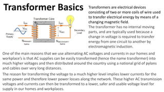
- 1. Transformer Basics Transformers are electrical devices consisting of two or more coils of wire used to transfer electrical energy by means of a changing magnetic field. The transformer has no internal moving parts, and are typically used because a change in voltage is required to transfer energy from one circuit to another by electromagnetic induction. One of the main reasons that we use alternating AC voltages and currents in our homes and workplace’s is that AC supplies can be easily transformed (hence the name transformer) into much higher voltages and then distributed around the country using a national grid of pylons and cables over very long distances. The reason for transforming the voltage to a much higher level implies lower currents for the same power and therefore lower power losses along the network. These higher AC transmission voltages and currents can then be transformed to a lower, safer and usable voltage level for supply in our homes and workplaces.
- 2. Mutual induction is the process by which a coil of wire magnetically induces a voltage into another coil located in close proximity to it. Transformers are capable of either increasing or decreasing the voltage and current levels of their supply, without modifying its frequency, or the amount of electrical power being transferred from one winding to another via the magnetic circuit. A single phase voltage transformer basically consists of two electrical coils of wire, one called the “Primary Winding” and another called the “Secondary Winding”. In a single-phase voltage transformer the primary is usually the side with the higher voltage. These two coils are not in electrical contact with each other but are instead wrapped together around a common closed magnetic iron circuit called the “core”. This soft iron core is not solid but made up of individual laminations connected together to help reduce the core’s magnetic losses. When a transformer is used to “increase” the voltage on its secondary winding with respect to the primary, it is called a Step-up transformer. When it is used to “decrease” the voltage on the secondary winding with respect to the primary it is called a Step-down transformer.
- 3. Electrical Power in a Transformer Another one of the transformer basics parameters is its power rating. The power rating of a transformer is obtained by simply multiplying the current by the voltage to obtain a rating in Volt-amperes, ( VA ). Small single phase transformers may be rated in volt-amperes only, but much larger power transformers are rated in units of Kilo volt-amperes, ( kVA ) where 1 kilo volt- ampere is equal to 1,000 volt-amperes, and units of Mega volt-amperes, ( MVA ) where 1 mega volt-ampere is equal to 1 million volt-amperes. (𝑃𝑜𝑤𝑒𝑟)𝑉𝐴 = 𝐼𝑉
- 4. Three Phase Transformers Three-phase Transformers are the backbone of electrical power distribution whether Delta or Star connected windings A three-phase electrical system in used to generate and transmit electric power over long distances for use by offices and industry. Three-phase voltages (and currents) are raised or lowered by means of three phase transformers as the three phase transformer can have its windings connected in various ways. If we take three single-phase transformers and connect their primary windings to each other and their secondary windings to each other in a fixed configuration, we can use the transformers on a three-phase supply.
- 5. A three phase transformer can be constructed either by connecting together three single-phase transformers, thereby forming a so- called three phase transformer bank, or by using one pre- assembled and balanced three phase transformer which consists of three pairs of single phase windings mounted onto one single laminated core. The advantages of building a single three phase transformer is that for the same kVA rating it will be smaller, cheaper and lighter than three individual single phase transformers connected together because the copper and iron core are used more effectively. The methods of connecting the primary and secondary windings are the same, whether using just one Three Phase Transformer or three separate Single Phase Transformers. Consider the circuit adjacent.
- 6. The primary and secondary windings of a transformer can be connected in different configuration as shown to meet practically any requirement. In the case of three phase transformer windings, two forms of connection are possible: “star” (wye) and “delta” (mesh). The combinations of the three windings may be with the primary delta-connected and the secondary star-connected, or star-delta, star-star or delta- delta, depending on the transformers use. Symbols are generally used on a three phase transformer to indicate the type or types of connections used with upper case Y for star connected and D for delta connected, with lower case y and d for their respective secondaries. Then, Star-Star would be labelled Yy, Delta-Delta would be labelled Dd. We now know that there are four different ways in which three single-phase transformers may be connected together between their primary and secondary three-phase circuits. These four standard configurations are given as: Delta-Delta (Dd), Star-Star (Yy), Star-Delta (Yd), and Delta- Star (Dy).
- 7. Transformers for high voltage operation with the star connections has the advantage of reducing the voltage on an individual transformer, reducing the number of turns required and an increase in the size of the conductors, making the coil windings easier and cheaper to insulate than delta transformers. The delta-delta connection nevertheless has one big advantage over the star-delta configuration, in that if one transformer of a group of three should become faulty or disabled, the two remaining ones will continue to deliver three-phase power with a capacity equal to approximately two thirds of the original output from the transformer unit. The relationship between line and phase voltages and currents in a three-phase system can be summarised as: Three Phase Voltage and Current Where, VL is the line-to-line voltage, and VP is the phase- to-neutral voltage on either the primary or the secondary side
- 8. Transformer Star – Star Connections
- 9. Transformer Delta – Delta Connections
- 10. Other possible connections for three phase transformers are star-delta Yd, where the primary winding is star-connected and the secondary is delta-connected or delta-star Dy with a delta- connected primary and a star-connected secondary. Delta-star connected transformers are widely used in low power distribution with the primary windings providing a three-wire balanced load to the utility company while the secondary windings provide the required 4th-wire neutral or earth connection. Star – Delta Turns Ratio Then with a 1:1 turns ratio, a star–delta connected transformer will provide a √3:1 step-down line-voltage ratio. Likewise, for a delta–star ( Dy ) connected transformer, with a 1:1 turns ratio, the transformer will provide a 1:√3 step-up line-voltage ratio. Then for a delta-star connected transformer the turns ratio becomes: Delta – Star Turns Ratio
- 11. Then for the four basic configurations of a three-phase transformer, we can list the transformers secondary voltages and currents with respect to the primary line voltage, VL and its primary line current IL as shown in the following table. Three-phase Transformer Line Voltage and Current Where: n equals the transformers “turns ratio” (T.R.) of the number of secondary windings NS, divided by the number of primary windings. ( NP NS/NP ) and VL is the line-to-line voltage with VP being the phase-to- neutral voltage.
- 12. Three Phase Transformer Example The primary winding of a delta-star ( Dy ) connected 50VA transformer is supplied with a 100 volt, 50Hz three-phase supply. If the transformer has 500 turns on the primary and 100 turns on the secondary winding, calculate the secondary side voltages and currents. 𝑡𝑢𝑟𝑛𝑠 𝑟𝑎𝑡𝑖𝑜 𝑛 = 𝑁𝑠 𝑁𝑝 = 100 500 = Power (VA) = 50𝑉𝐴 𝑉𝑙𝑖𝑛𝑒 = 100V 𝑁𝑝 = 500 𝑁𝑠 = 100 0.2 𝑉𝑙𝑖𝑛𝑒(𝑠) = 3 × 𝑛 × 𝑉𝑙𝑖𝑛𝑒(𝑝) = 3 × 0.2 × 100 = 34.64𝑉 𝐼𝑙𝑖𝑛𝑒(𝑝) = 𝑉𝐴 3 × 𝑉𝑙𝑖𝑛𝑒(𝑝) = 50 3 × 100 = 0.289𝐴 𝐼(𝑠) = 𝐼(𝑝) 3 × 𝑛 = 0.289 3 × 0.2 = 0.834𝐴