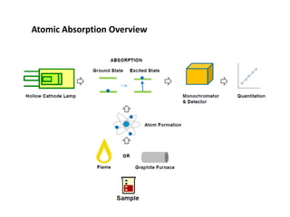
Atomic absorption spectroscopy is a technique used to determine the concentration of metals in solutions. It works by atomizing the sample and measuring the absorption of light from a hollow cathode lamp, which is characteristic of the metal of interest. There are two main types - flame atomic absorption which uses a flame to atomize the liquid sample, and graphite furnace atomic absorption which introduces a small solid or liquid sample directly into a graphite furnace for higher sensitivity. The technique can be used to analyze over 62 different metals at low detection limits.