Downloaded 12 times
![ELECTRICAL PROJECTS USING MATLAB/SIMULINK
Gmail: asokatechnologies@gmail.com, Website: http://www.asokatechnologies.in
0-9347143789/9949240245
For Simulation Results of the project Contact Us
Gmail: asokatechnologies@gmail.com, Website: http://www.asokatechnologies.in
0-9347143789/9949240245
Fig 8. Harmonic of spectrum Line current of 3-level inverter for R= 15,L=24.2 mH
CONCLUSION:
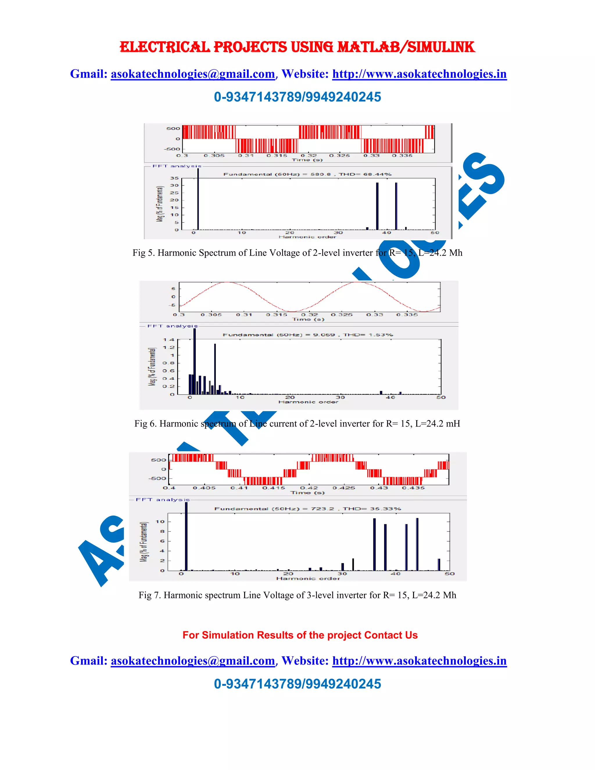
The simulation of the inverters namely conventional three and two level inverter was carried
using sinusoidal pulse width modulation (SPWM) .it has shown that decrease in voltage and
current THD in moving from two level inverter to three level inverter. This paper briefly
explains theory of sinusoidal pulse width modulation (SPWM) for two and three level inverter
and performance of both inverters was tested using RL load. It has shown that load current for
three level inverter are much more sinusoidal and improvement in the line current waveform and
decrease in the THD from two level to three level inverter and decrease in the THD as the
frequency is increased.
REFERENCES:
[1] J. S. Lai and F.Z. Peng “Multilevel Converters – A new breed of power converters” IEEE
Trans. Ind Applicant , Vol. 32, May/June 1996.
[2] Jose Roderiguez, Jih-Sheng Lai and Fang Zheng Reng, “Multilevel Inverters” A survey of
topologies ,control, and applications “,IEEE Trans. On Ind.Electronics, vol No.[4], August 2002.](https://image.slidesharecdn.com/at46-150617102753-lva1-app6891/75/Matlab-based-Simulation-Analysis-of-Three-level-SPWM-Inverter-5-2048.jpg)
![ELECTRICAL PROJECTS USING MATLAB/SIMULINK
Gmail: asokatechnologies@gmail.com, Website: http://www.asokatechnologies.in
0-9347143789/9949240245
For Simulation Results of the project Contact Us
Gmail: asokatechnologies@gmail.com, Website: http://www.asokatechnologies.in
0-9347143789/9949240245
[3] A. Nabae, I Takashashi, and H. Akagi, “ A new neutral –point clamped PWM inverter,”
IEEE Trans. Ind Application Vol. No. IA-17,PP 518-523,Sept/oc 1981.
[4] P.K.Chaturvedi, S. Jain, Pramod Agrawal “ Modeling , Simulation and Analysis of Three
level Neutral Point CLAMPED inverter using matlab/Simulink/Power System Blockst”
[5] Bor-Ren Lin & Hsin – Hung Lu “ A Novel Multilevel PWM Control Scheme of the
AC/DC/AC converter for AC Drives”IEEE Trans on ISIE, 1999.](https://image.slidesharecdn.com/at46-150617102753-lva1-app6891/75/Matlab-based-Simulation-Analysis-of-Three-level-SPWM-Inverter-6-2048.jpg)

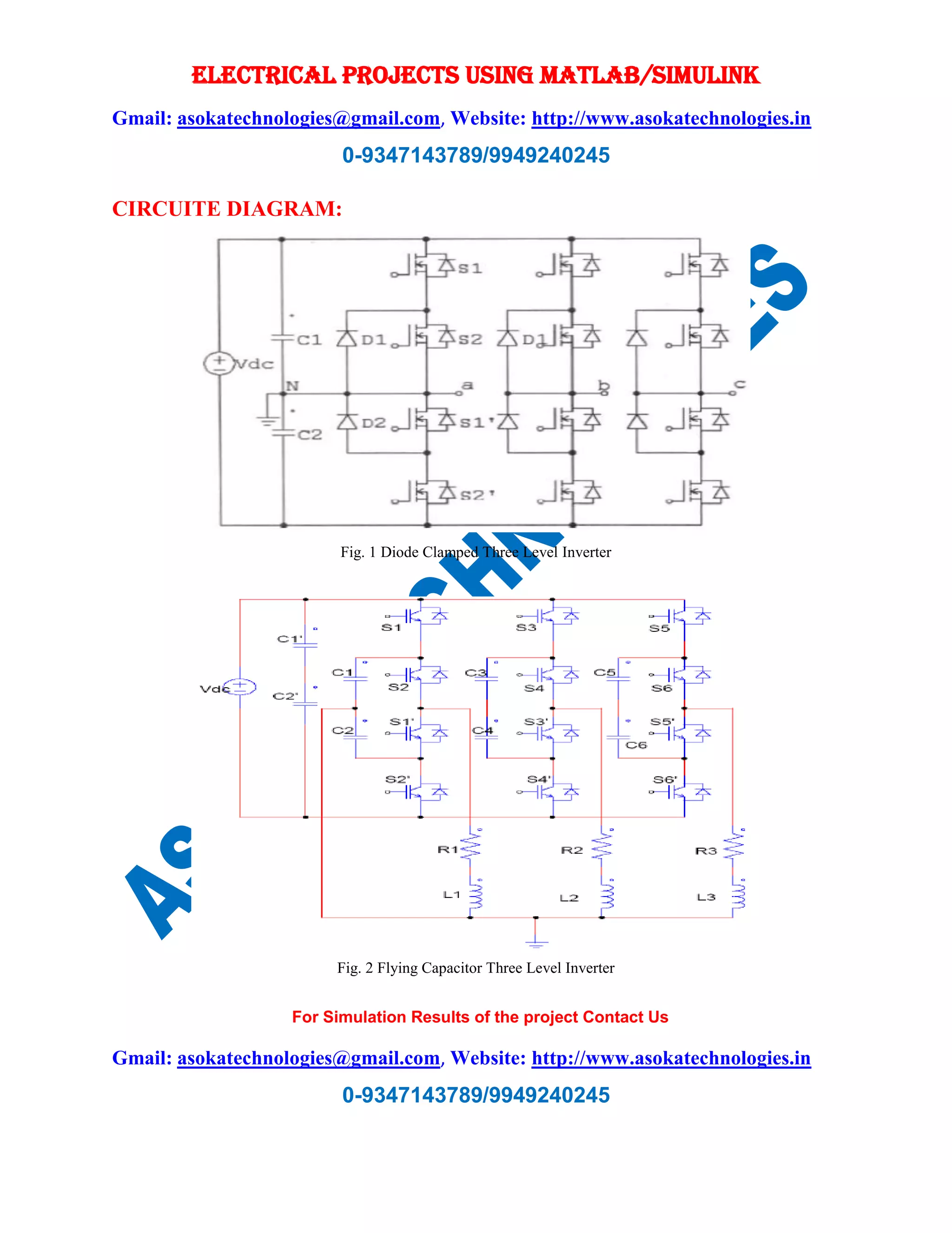
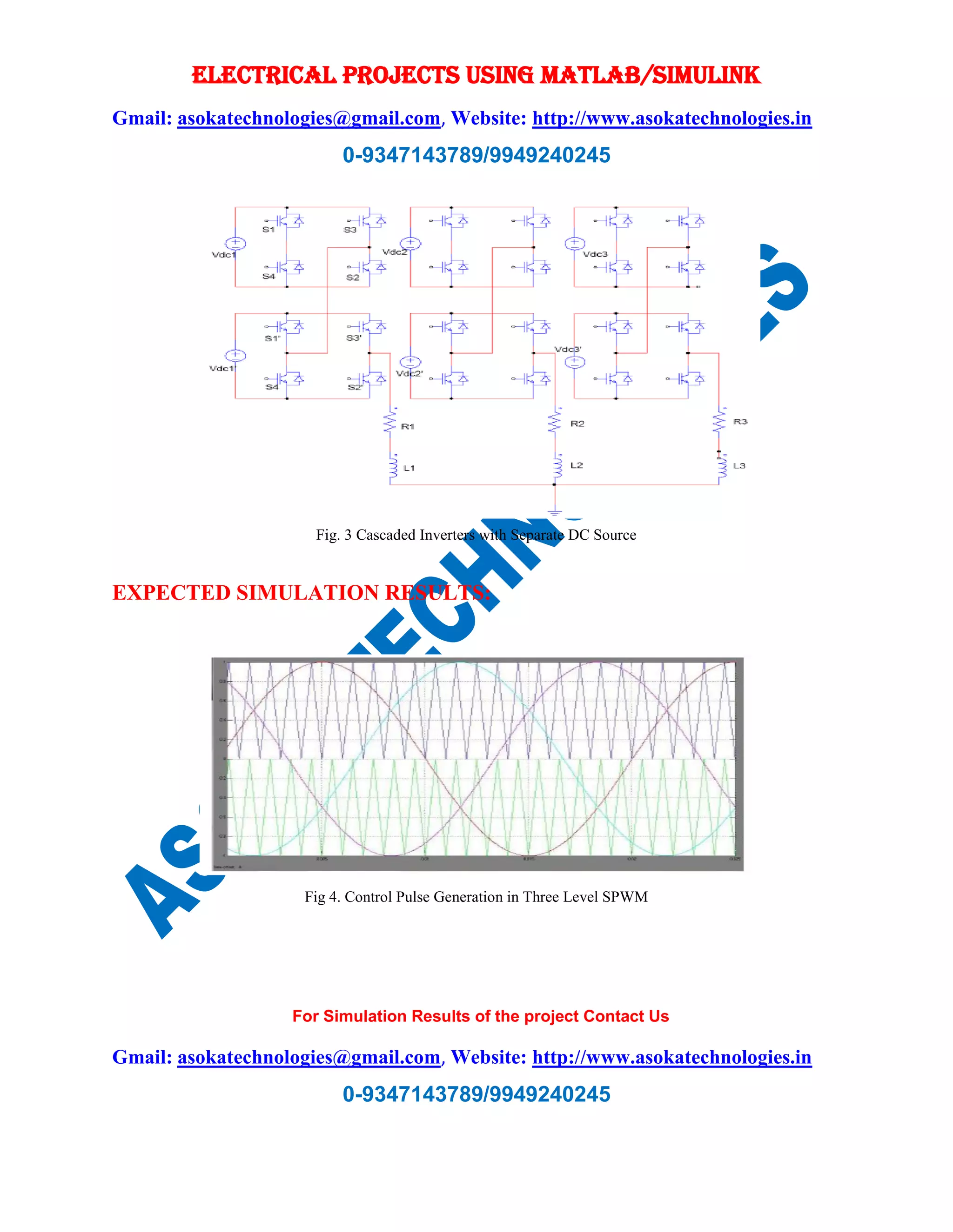
The document discusses the simulation and analysis of a three-level SPWM inverter using MATLAB/Simulink, emphasizing its advantages in achieving smoother output voltage and reduced harmonic distortion compared to two-level inverters. Various topologies and SPWM techniques are explored, along with simulation results showing improved performance metrics, such as decreased total harmonic distortion (THD). The paper includes circuit diagrams, expected simulation results, and references to related literature.