Download as PDF, PPTX


AutoCAD is a commercial computer-aided design software. These tutorials are intended for absolute beginners to learn the basic tools and interface of AutoCAD. The interface includes the ribbon, command bar, and status bar. Important commands include line, rectangle, circle, arc, and modifying tools like copy, move, offset, and array. Learning how to use these basic tools is essential for producing technical drawings in AutoCAD.
AutoCAD is a CAD software by Autodesk for beginners, downloadable for free. The tutorials cover design basics, tools, and practical usage.
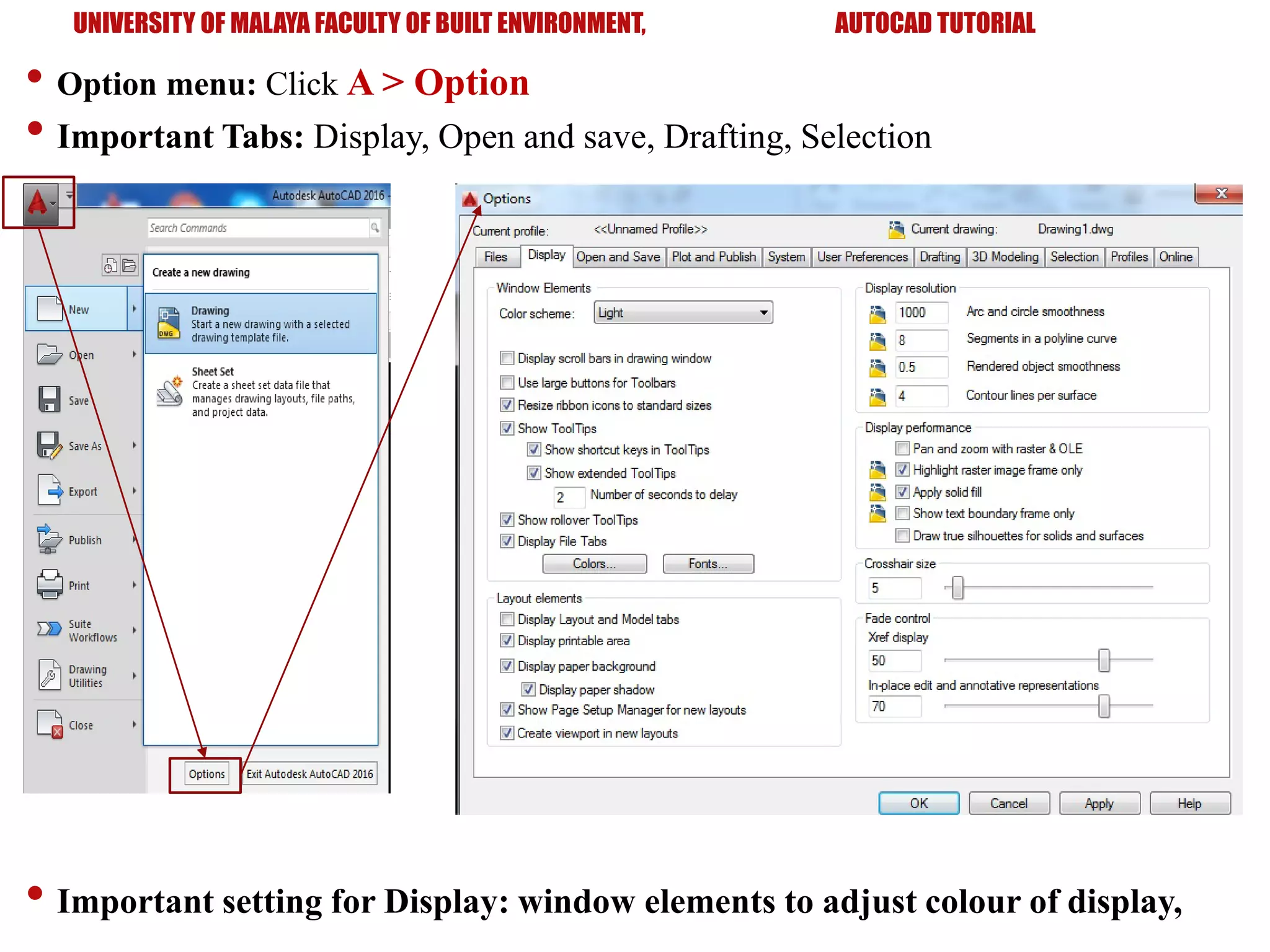
Introduction to the AutoCAD interface including installation, menu navigation, ribbons, command bars, and setting units.
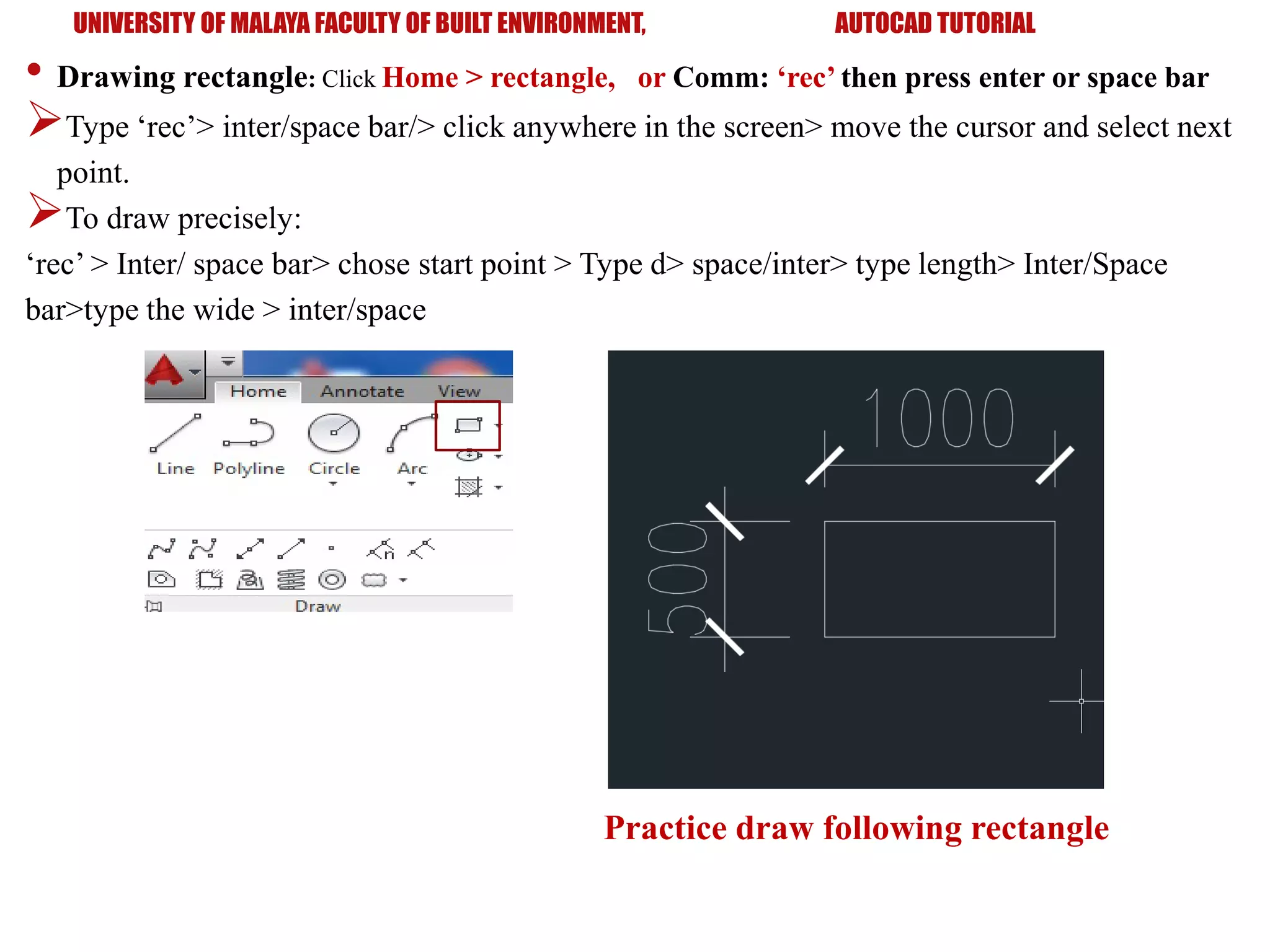
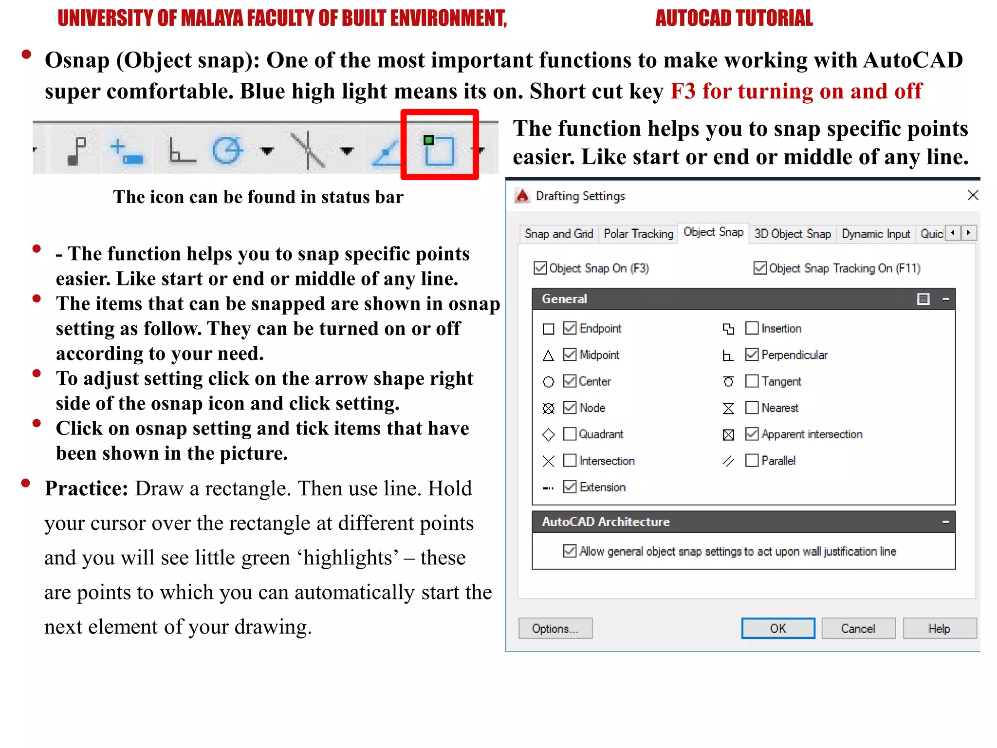
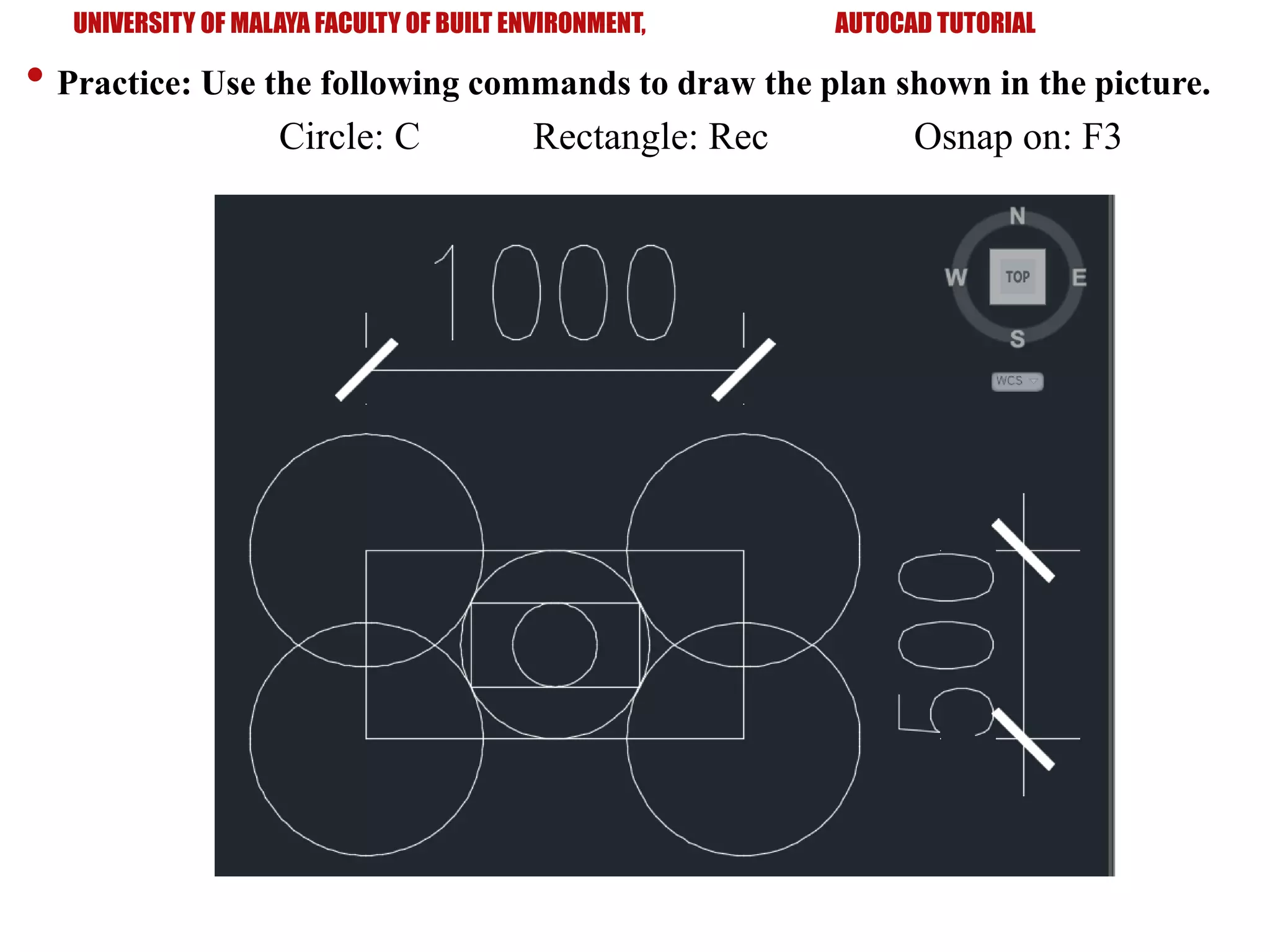
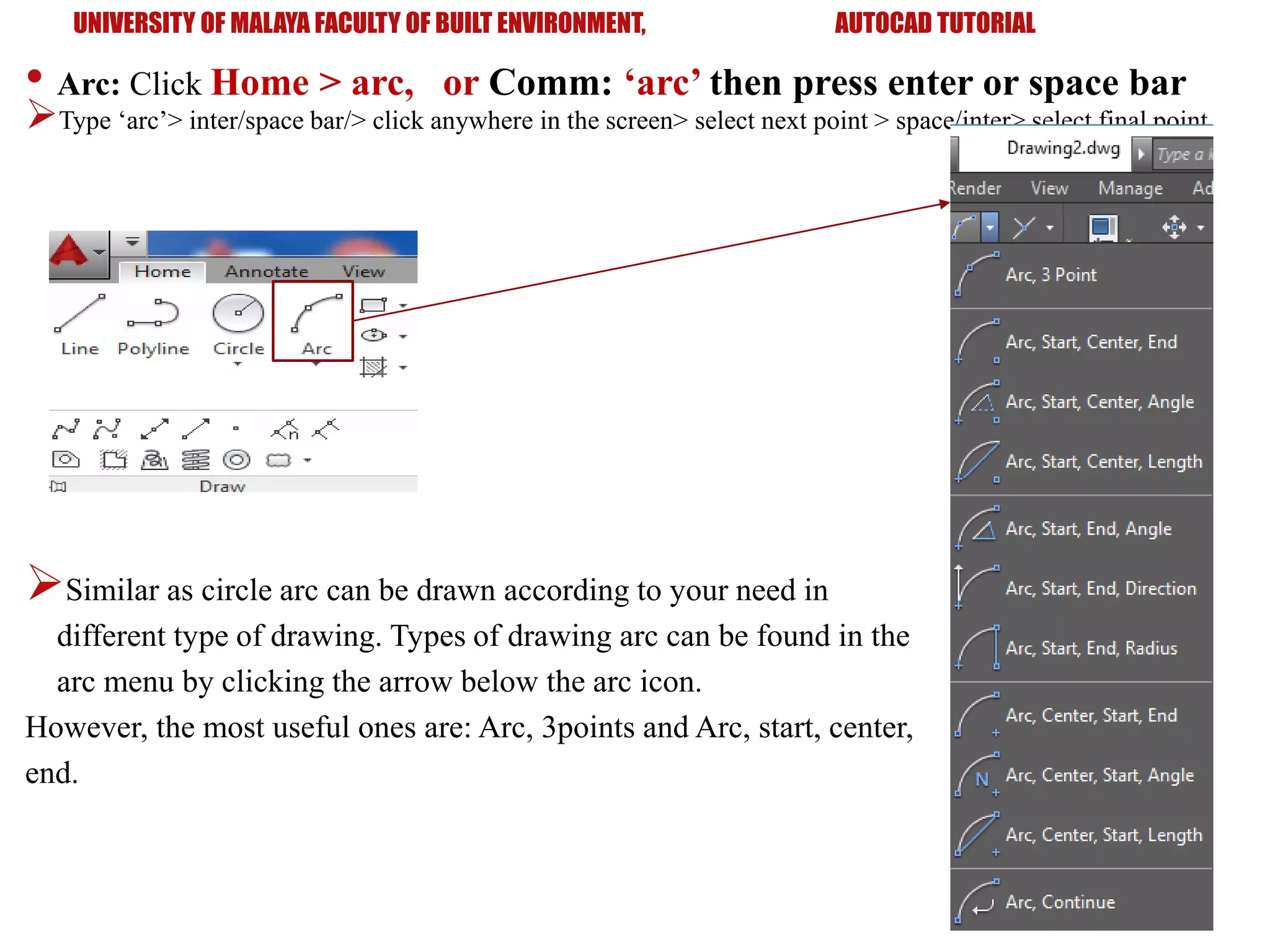
Tutorial on basic drawing commands in AutoCAD like lines, rectangles, circles, and arcs including their precise functionalities.
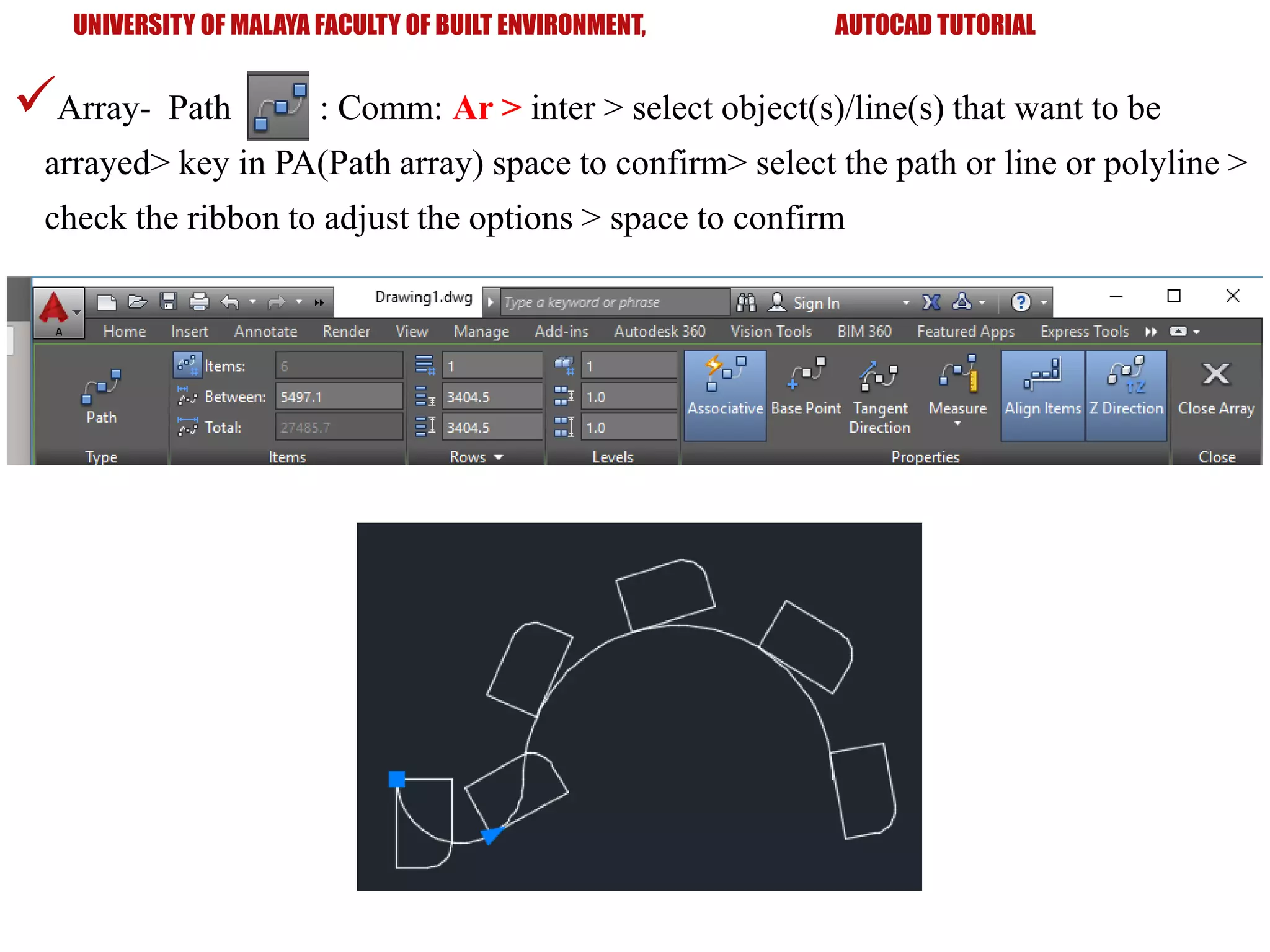
Discusses modification tools for objects in AutoCAD like copy, move, offset, mirror, and array techniques.
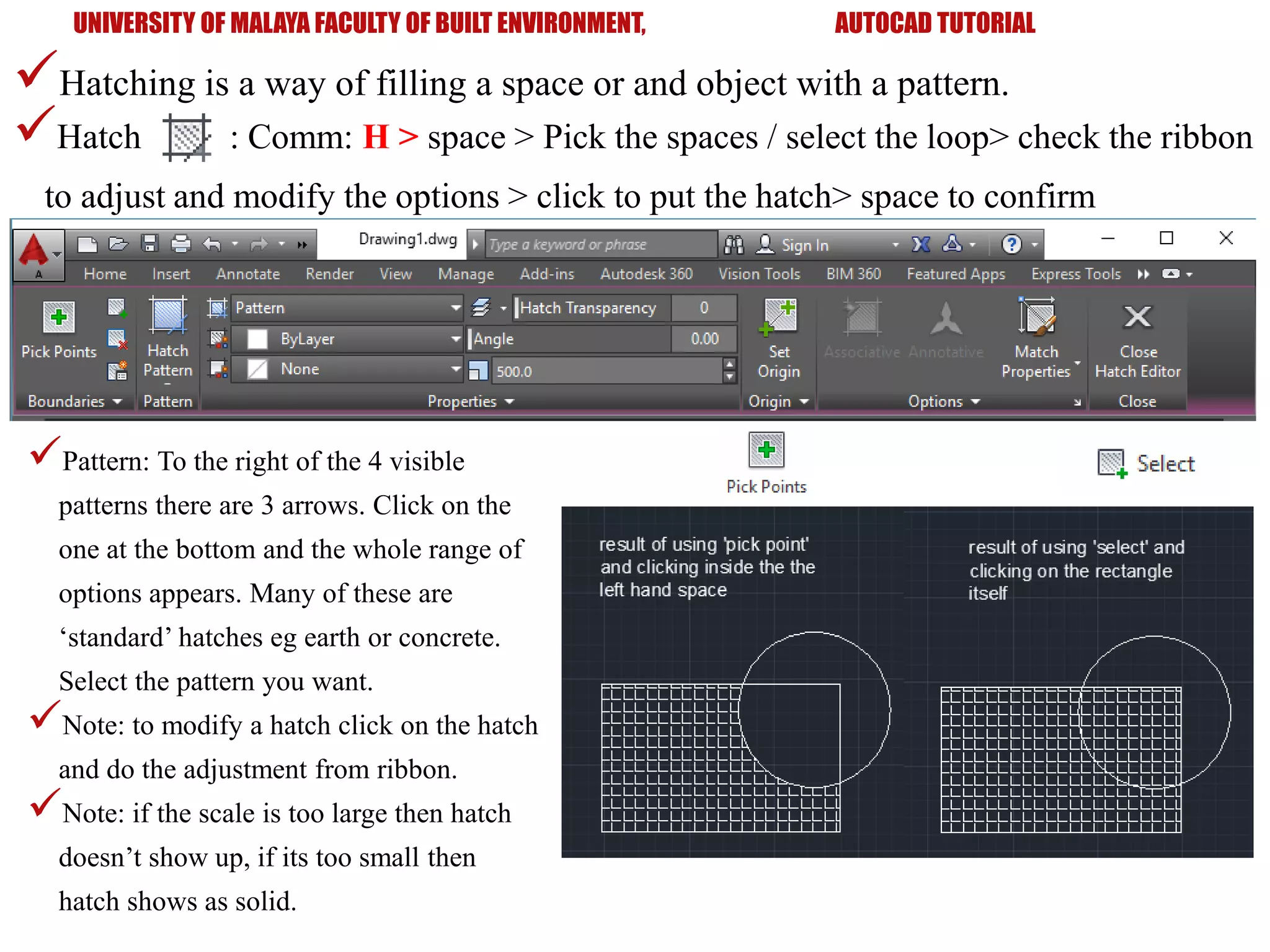
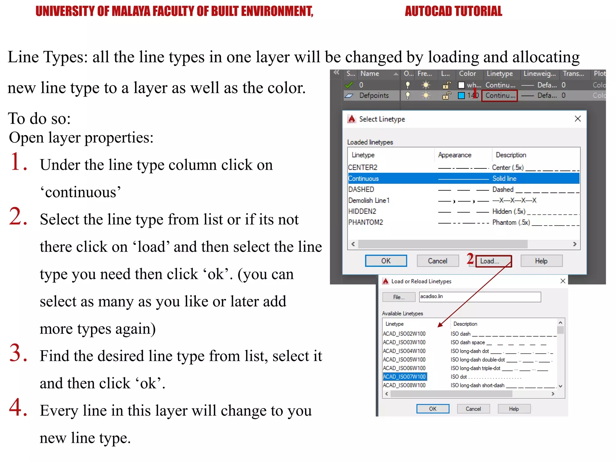
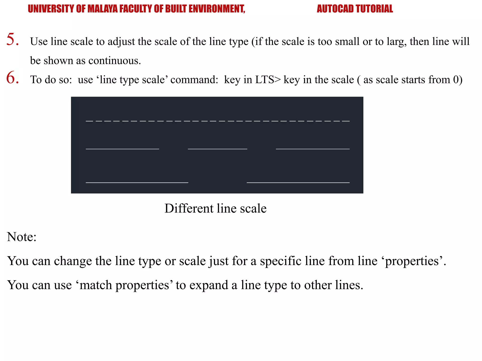
Explains hatching patterns, object properties, layers management, and line types to enhance drawing clarity.
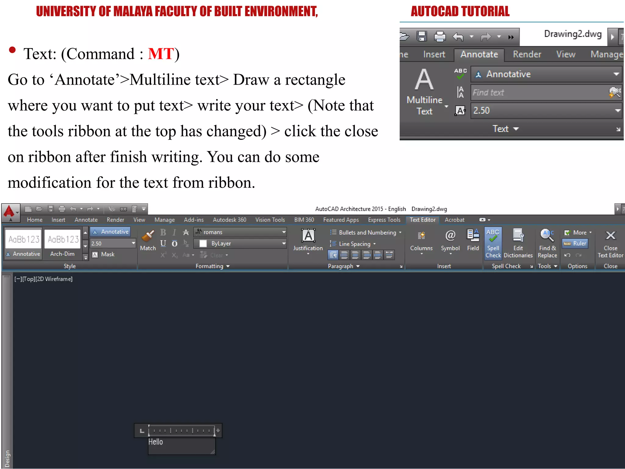
Introduction to blocks, creating and inserting them, dimensioning tools, text styles, and practice exercise to apply learned skills.
Closing thanks for attention and engagement in learning AutoCAD.