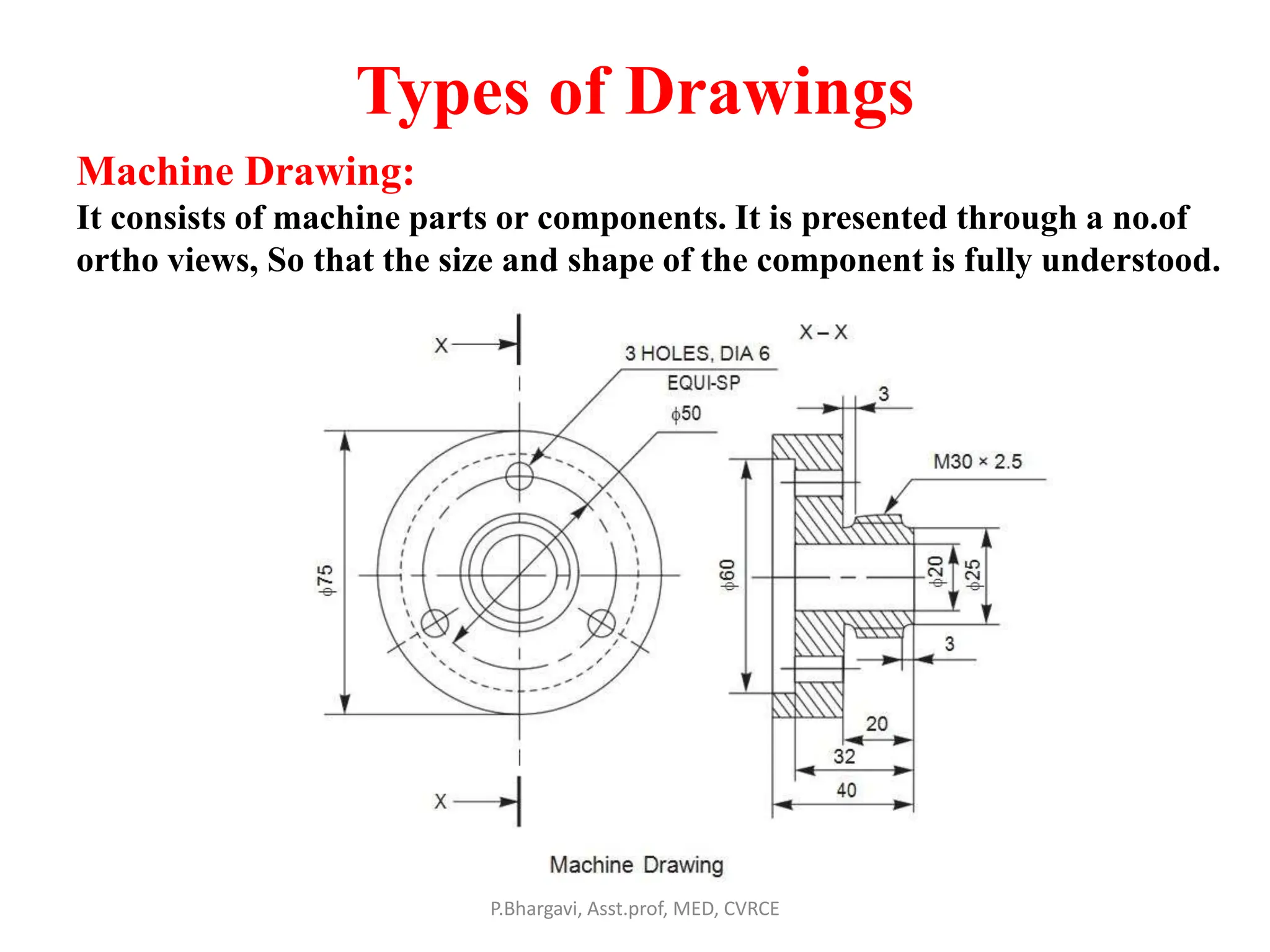
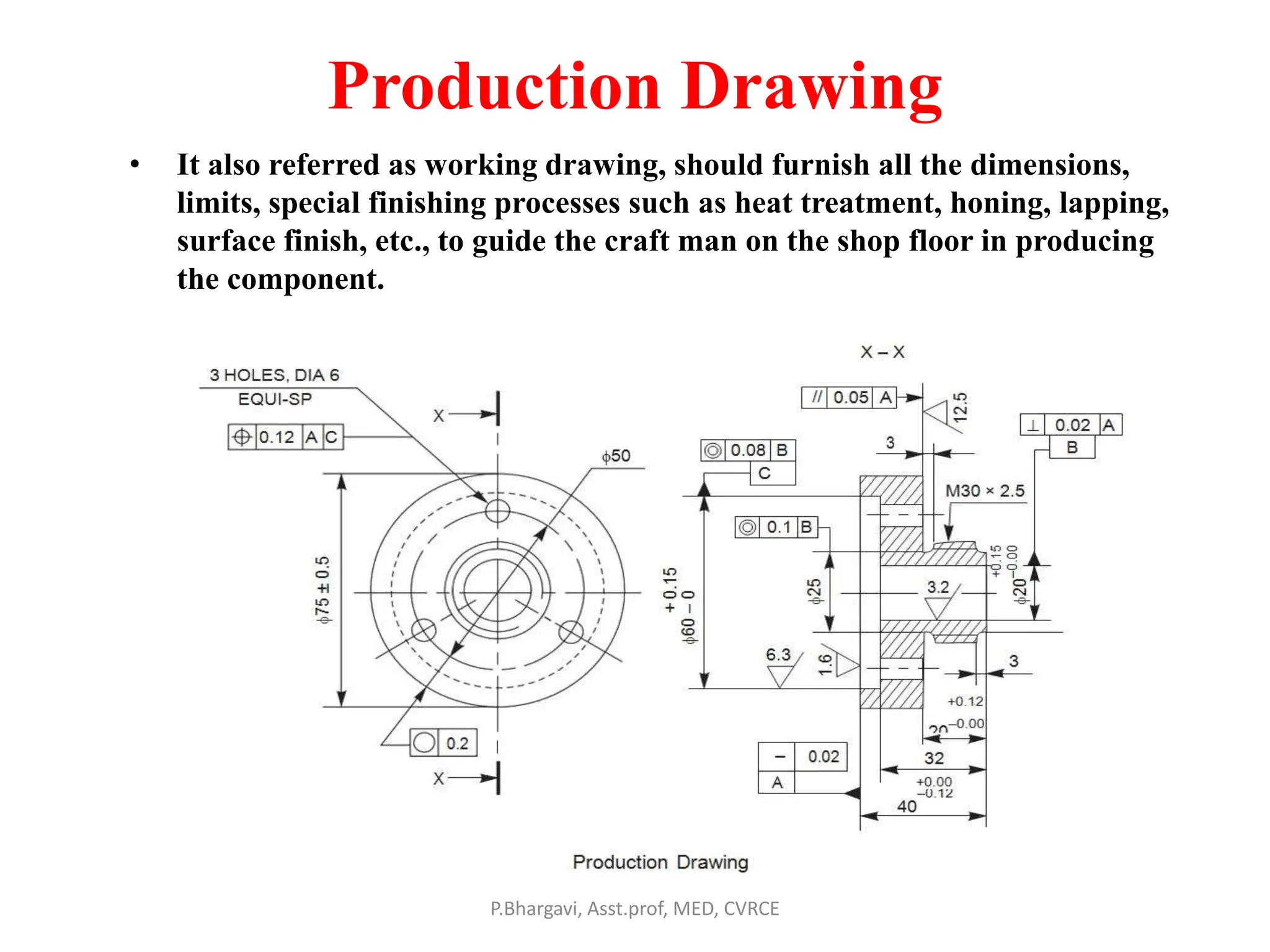
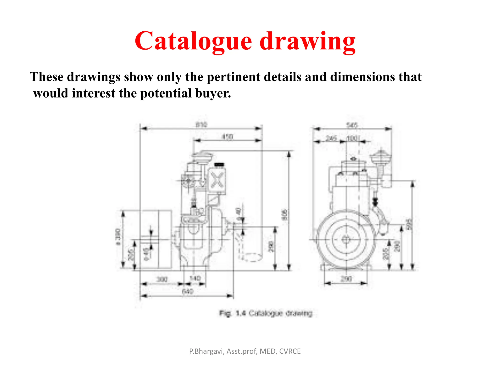
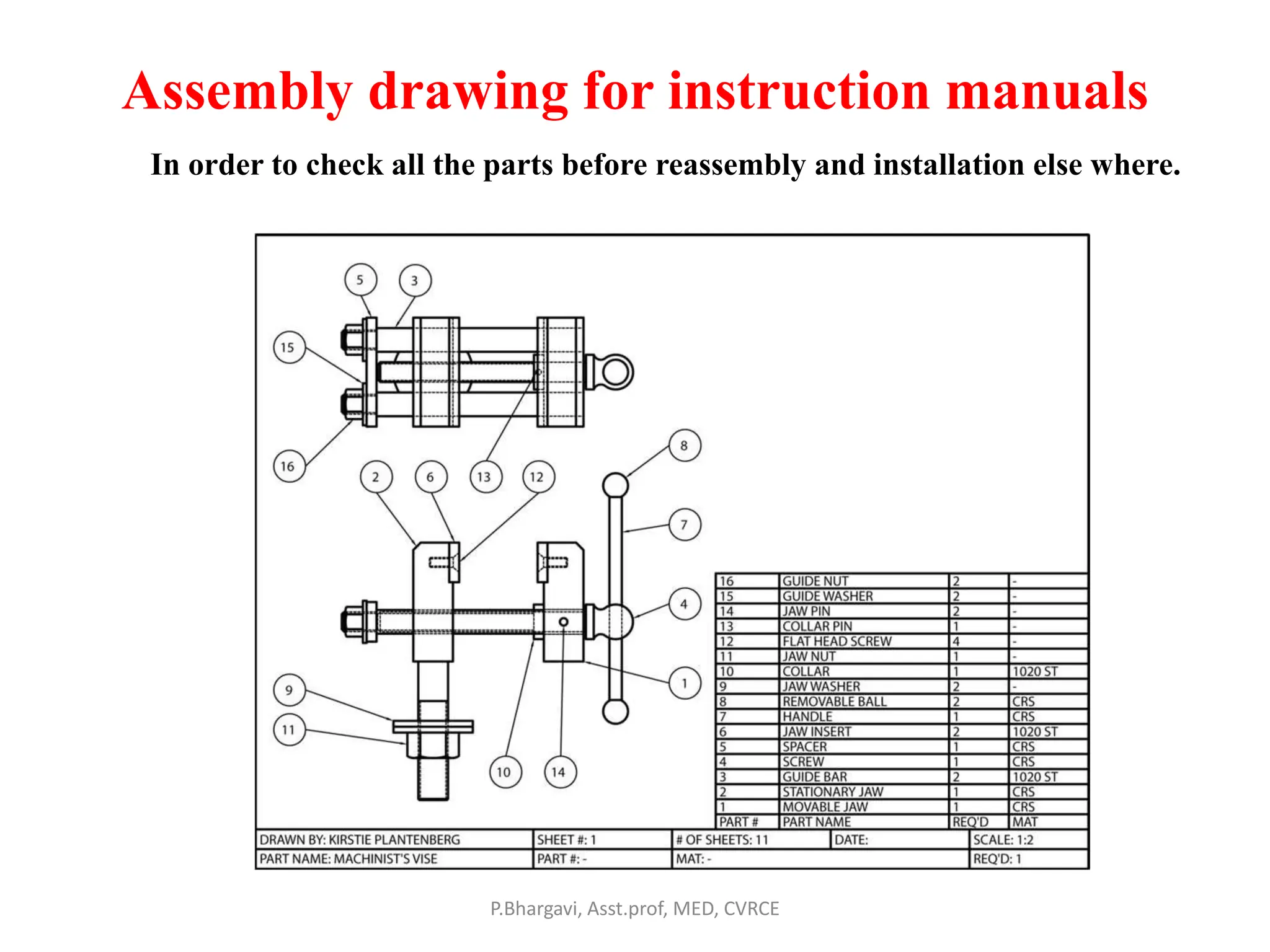
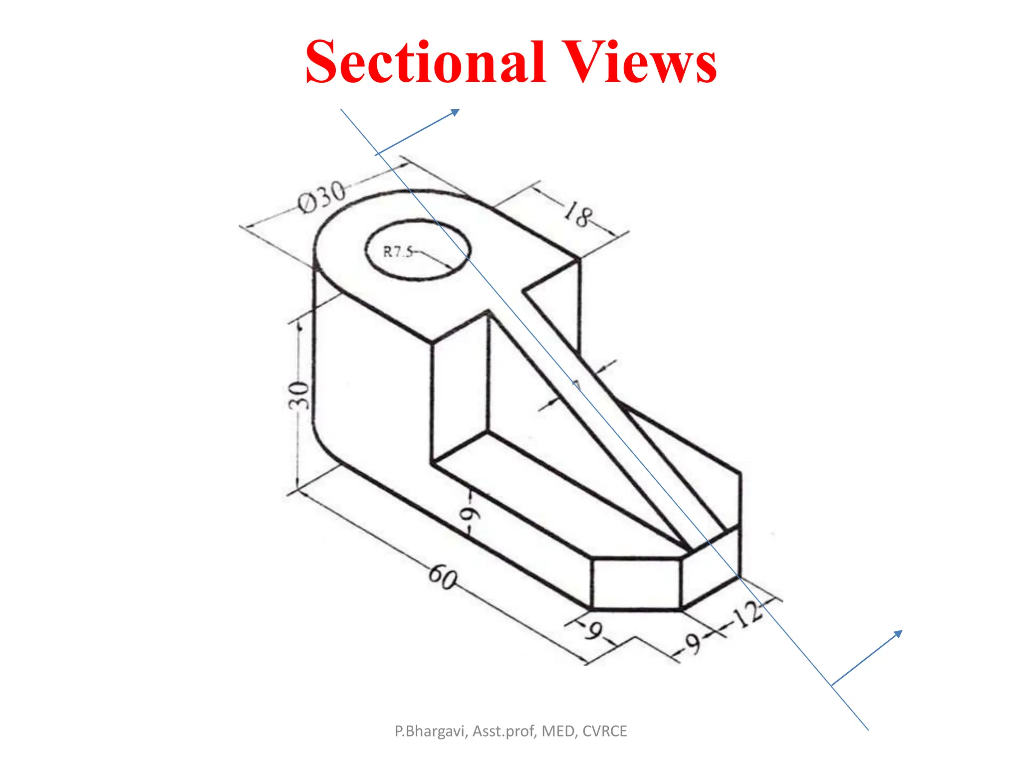
Machine Drawing through Auto CAD
Introduction
P.Bhargavi, Asst.prof, MED, CVRCE
List of Experiments
• Introduction to AutoCAD: Getting started with AutoCAD - User
Interface – Standard annotation tool bar – Drawing templates- New File-
save- Ribbon Panel-workspace- Command bar. Tool bars– Status bar –
Display control commands and plotting.
1. Conventional representation of materials, common machine elements
and parts such as Screws, nuts, bolts, keys, gears, webs, and ribs.
(Drawing of Machine Elements and simple parts. Selection of Views,
additional views for the following machine elements and parts with every
drawing proportion.)
P.Bhargavi, Asst.prof, MED, CVRCE
List of Experiments
2. Machine Drawing Conventions: Need for drawing conventions – introduction
to IS conventions
b) Types of sections – selection of section planes and drawing of sections and auxiliary
sectional views. Parts not usually sectioned.
c) Methods of dimensioning, general rules for sizes and placement of dimensions for
holes, centers, curved and tapered features.
d) Title boxes, size, location and details - common abbreviations & their liberal usage.
e) Types of Drawings – working drawings for machine parts.
(Drawing of Machine Elements and simple parts. Selection of Views, additional
views for the following machine elements and parts with every drawing
proportion.)
P.Bhargavi, Asst.prof, MED, CVRCE
List of Experiments
3. Popular forms of Screw threads, bolts, nuts, stud bolts, tap bolts, set screws.
4. Keys, cotter joints and knuckle joint.
5. Shaft couplings
6. Journal, pivot and collar and foot step bearings (Plummer block), Riveted joints
for plates
7. Stuffing box, cross heads,
8. Eccentrics, Petrol Engine connecting rod, piston assembly.
9. A) Screws jack, Machine Vices,
B) Tailstock.
10 A) Steam stop valve
B) Feed check valve.
P.Bhargavi, Asst.prof, MED, CVRCE
Orthographic Projection
• Projection: Getting an image of the object on
the picture plane when light rays are projected
on it.
• If these rays are perpendicular to plane of
projection and to the object then the image
obtained on the plane of projection is known as
orthographic view.
P.Bhargavi, Asst.prof, MED, CVRCE
Contents
• Classification of Drawings
• Types of drawing sheets
• Drawing sheet layout
• Types of lines
• Arrangements of dimensioning & rules.
• Conventional representations of materials &
machine components
• Rules of sectioning
P.Bhargavi, Asst.prof, MED, CVRCE
Types of Drawings
Machine Drawing:
It consists of machine parts or components. It is presented through a no.of
ortho views, So that the size and shape of the component is fully understood.
P.Bhargavi, Asst.prof, MED, CVRCE
Production Drawing
• It also referred as working drawing, should furnish all the dimensions,
limits, special finishing processes such as heat treatment, honing, lapping,
surface finish, etc., to guide the craft man on the shop floor in producing
the component.
P.Bhargavi, Asst.prof, MED, CVRCE
Part Drawing
• Detailed Drawing
of a component to
felicitate its
manufacturing.
P.Bhargavi, Asst.prof, MED, CVRCE
Assembly Drawing
• A drawing that shows the various parts of machine in
their correct working locations is an assembly drawing.
• Types of Assembly drawings:
1. Design assembly drawing
2. Detailed assembly
3. Sub- assembly drawing
4. Installation Assembly drawing
5. Catalogue drawing
6. Assembly drawing for
instruction manuals
7. Exploded assembly drawing
8. Schematic assembly drawing.
9. Machine shop drawing
P.Bhargavi, Asst.prof, MED, CVRCE
Catalogue drawing
P.Bhargavi, Asst.prof, MED, CVRCE
These drawings show only the pertinent details and dimensions that
would interest the potential buyer.
Assembly drawing for instruction manuals
P.Bhargavi, Asst.prof, MED, CVRCE
In order to check all the parts before reassembly and installation else where.
Exploded assembly drawing
P.Bhargavi, Asst.prof, MED, CVRCE
Exploded pictorial views are supplied to meet instruction manual requirements.
Schematic assembly drawing
• Schematic representation of all the elements of a machine by
their conventional representation.
P.Bhargavi, Asst.prof, MED, CVRCE
Machine shop drawing
P.Bhargavi, Asst.prof, MED, CVRCE
Rough castings and forgings sent to machine shop for finishing
operation. Machine shop drawing gives only the information
necessary for machining.
P.Bhargavi, Asst.prof, MED, CVRCE
Drawing sheet layout
P.Bhargavi, Asst.prof, MED, CVRCE
Types of lines
P.Bhargavi, Asst.prof, MED, CVRCE
Hidden and axis line techniques
P.Bhargavi, Asst.prof, MED, CVRCE
Leader line
P.Bhargavi, Asst.prof, MED, CVRCE
System of Dimensioning
• Aligned system
1. Chain
2. Parallel
• Unidirectional system
1. Chain
2. Parallel
• Progressive
P.Bhargavi, Asst.prof, MED, CVRCE
System of Dimensioning
P.Bhargavi, Asst.prof, MED, CVRCE
Aligned system
Chain dimensioning
P.Bhargavi, Asst.prof, MED, CVRCE
Unidirectional system
Parallel dimensioning
P.Bhargavi, Asst.prof, MED, CVRCE
Progressive
P.Bhargavi, Asst.prof, MED, CVRCE
Dimensioning of Diameter, arc, chord & angles
P.Bhargavi, Asst.prof, MED, CVRCE
Method of indicating Notes
P.Bhargavi, Asst.prof, MED, CVRCE
• Meaning of notes and Abbreviations
Refer Text book pg.no:36,37,38.
(Text Book Machine Drawing by K.L. Narayan)
P.Bhargavi, Asst.prof, MED, CVRCE
Conventional representation of Materials
A mixture of cement,
sand and Gravel
P.Bhargavi, Asst.prof, MED, CVRCE
Conventional representation of Machine
components
P.Bhargavi, Asst.prof, MED, CVRCE
Conventional representation of Machine
components
P.Bhargavi, Asst.prof, MED, CVRCE
Conventional representation of Machine
components
P.Bhargavi, Asst.prof, MED, CVRCE
Sections
• In order to see the inner details of a machine
component, the object is imagined to be cut by
a cutting plane and the section is viewed after
the removal of cut portion.
P.Bhargavi, Asst.prof, MED, CVRCE
Cutting plane indication
P.Bhargavi, Asst.prof, MED, CVRCE
• Sections are made by cutting planes and are designated by capital letters and
the direction of viewing is indicated by arrow marks.
P.Bhargavi, Asst.prof, MED, CVRCE
Hatching of Sections
Hatching of Adjacent
components
P.Bhargavi, Asst.prof, MED, CVRCE
Sectioning along two parallel planes
P.Bhargavi, Asst.prof, MED, CVRCE
Sections not to be hatched
* Fasteners * Shafts , Ribs
P.Bhargavi, Asst.prof, MED, CVRCE
Sections not to be hatched
P.Bhargavi, Asst.prof, MED, CVRCE
Sections not to be hatched
P.Bhargavi, Asst.prof, MED, CVRCE
Sectional Views
P.Bhargavi, Asst.prof, MED, CVRCE
Sectional Views
P.Bhargavi, Asst.prof, MED, CVRCE
Sectional Views
P.Bhargavi, Asst.prof, MED, CVRCE
Sectional Views
P.Bhargavi, Asst.prof, MED, CVRCE

Machine Drawing Introduction.pptx

  • 1.
    Machine Drawing throughAuto CAD Introduction P.Bhargavi, Asst.prof, MED, CVRCE
  • 2.
    List of Experiments •Introduction to AutoCAD: Getting started with AutoCAD - User Interface – Standard annotation tool bar – Drawing templates- New File- save- Ribbon Panel-workspace- Command bar. Tool bars– Status bar – Display control commands and plotting. 1. Conventional representation of materials, common machine elements and parts such as Screws, nuts, bolts, keys, gears, webs, and ribs. (Drawing of Machine Elements and simple parts. Selection of Views, additional views for the following machine elements and parts with every drawing proportion.) P.Bhargavi, Asst.prof, MED, CVRCE
  • 3.
    List of Experiments 2.Machine Drawing Conventions: Need for drawing conventions – introduction to IS conventions b) Types of sections – selection of section planes and drawing of sections and auxiliary sectional views. Parts not usually sectioned. c) Methods of dimensioning, general rules for sizes and placement of dimensions for holes, centers, curved and tapered features. d) Title boxes, size, location and details - common abbreviations & their liberal usage. e) Types of Drawings – working drawings for machine parts. (Drawing of Machine Elements and simple parts. Selection of Views, additional views for the following machine elements and parts with every drawing proportion.) P.Bhargavi, Asst.prof, MED, CVRCE
  • 4.
    List of Experiments 3.Popular forms of Screw threads, bolts, nuts, stud bolts, tap bolts, set screws. 4. Keys, cotter joints and knuckle joint. 5. Shaft couplings 6. Journal, pivot and collar and foot step bearings (Plummer block), Riveted joints for plates 7. Stuffing box, cross heads, 8. Eccentrics, Petrol Engine connecting rod, piston assembly. 9. A) Screws jack, Machine Vices, B) Tailstock. 10 A) Steam stop valve B) Feed check valve. P.Bhargavi, Asst.prof, MED, CVRCE
  • 5.
    Orthographic Projection • Projection:Getting an image of the object on the picture plane when light rays are projected on it. • If these rays are perpendicular to plane of projection and to the object then the image obtained on the plane of projection is known as orthographic view. P.Bhargavi, Asst.prof, MED, CVRCE
  • 6.
  • 7.
    Contents • Classification ofDrawings • Types of drawing sheets • Drawing sheet layout • Types of lines • Arrangements of dimensioning & rules. • Conventional representations of materials & machine components • Rules of sectioning P.Bhargavi, Asst.prof, MED, CVRCE
  • 8.
    Types of Drawings MachineDrawing: It consists of machine parts or components. It is presented through a no.of ortho views, So that the size and shape of the component is fully understood. P.Bhargavi, Asst.prof, MED, CVRCE
  • 9.
    Production Drawing • Italso referred as working drawing, should furnish all the dimensions, limits, special finishing processes such as heat treatment, honing, lapping, surface finish, etc., to guide the craft man on the shop floor in producing the component. P.Bhargavi, Asst.prof, MED, CVRCE
  • 10.
    Part Drawing • DetailedDrawing of a component to felicitate its manufacturing. P.Bhargavi, Asst.prof, MED, CVRCE
  • 11.
    Assembly Drawing • Adrawing that shows the various parts of machine in their correct working locations is an assembly drawing. • Types of Assembly drawings: 1. Design assembly drawing 2. Detailed assembly 3. Sub- assembly drawing 4. Installation Assembly drawing 5. Catalogue drawing 6. Assembly drawing for instruction manuals 7. Exploded assembly drawing 8. Schematic assembly drawing. 9. Machine shop drawing P.Bhargavi, Asst.prof, MED, CVRCE
  • 12.
    Catalogue drawing P.Bhargavi, Asst.prof,MED, CVRCE These drawings show only the pertinent details and dimensions that would interest the potential buyer.
  • 13.
    Assembly drawing forinstruction manuals P.Bhargavi, Asst.prof, MED, CVRCE In order to check all the parts before reassembly and installation else where.
  • 14.
    Exploded assembly drawing P.Bhargavi,Asst.prof, MED, CVRCE Exploded pictorial views are supplied to meet instruction manual requirements.
  • 15.
    Schematic assembly drawing •Schematic representation of all the elements of a machine by their conventional representation. P.Bhargavi, Asst.prof, MED, CVRCE
  • 16.
    Machine shop drawing P.Bhargavi,Asst.prof, MED, CVRCE Rough castings and forgings sent to machine shop for finishing operation. Machine shop drawing gives only the information necessary for machining.
  • 17.
  • 18.
    Drawing sheet layout P.Bhargavi,Asst.prof, MED, CVRCE
  • 19.
    Types of lines P.Bhargavi,Asst.prof, MED, CVRCE
  • 20.
    Hidden and axisline techniques P.Bhargavi, Asst.prof, MED, CVRCE
  • 21.
  • 22.
    System of Dimensioning •Aligned system 1. Chain 2. Parallel • Unidirectional system 1. Chain 2. Parallel • Progressive P.Bhargavi, Asst.prof, MED, CVRCE
  • 23.
  • 24.
  • 25.
  • 26.
  • 27.
    Dimensioning of Diameter,arc, chord & angles P.Bhargavi, Asst.prof, MED, CVRCE
  • 28.
  • 29.
    Method of indicatingNotes P.Bhargavi, Asst.prof, MED, CVRCE
  • 30.
    • Meaning ofnotes and Abbreviations Refer Text book pg.no:36,37,38. (Text Book Machine Drawing by K.L. Narayan) P.Bhargavi, Asst.prof, MED, CVRCE
  • 31.
    Conventional representation ofMaterials A mixture of cement, sand and Gravel P.Bhargavi, Asst.prof, MED, CVRCE
  • 32.
    Conventional representation ofMachine components P.Bhargavi, Asst.prof, MED, CVRCE
  • 33.
    Conventional representation ofMachine components P.Bhargavi, Asst.prof, MED, CVRCE
  • 34.
    Conventional representation ofMachine components P.Bhargavi, Asst.prof, MED, CVRCE
  • 35.
    Sections • In orderto see the inner details of a machine component, the object is imagined to be cut by a cutting plane and the section is viewed after the removal of cut portion. P.Bhargavi, Asst.prof, MED, CVRCE
  • 36.
    Cutting plane indication P.Bhargavi,Asst.prof, MED, CVRCE • Sections are made by cutting planes and are designated by capital letters and the direction of viewing is indicated by arrow marks.
  • 37.
  • 38.
    Hatching of Sections Hatchingof Adjacent components P.Bhargavi, Asst.prof, MED, CVRCE
  • 39.
    Sectioning along twoparallel planes P.Bhargavi, Asst.prof, MED, CVRCE
  • 40.
    Sections not tobe hatched * Fasteners * Shafts , Ribs P.Bhargavi, Asst.prof, MED, CVRCE
  • 41.
    Sections not tobe hatched P.Bhargavi, Asst.prof, MED, CVRCE
  • 42.
    Sections not tobe hatched P.Bhargavi, Asst.prof, MED, CVRCE
  • 43.
  • 44.
  • 45.
  • 46.