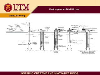
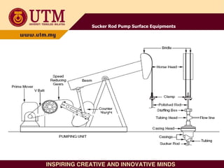
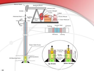
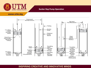
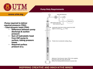
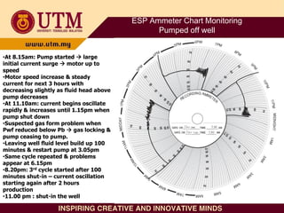
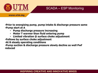
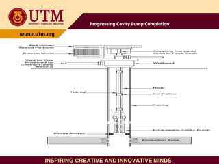
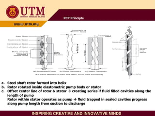
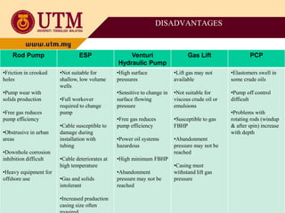
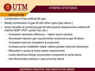
2. Students must be able to:
– Distinguish different type of artificial lift system
– Identify & select the requirement for artificial lift
system
ARTIFICIAL LIFT SYSTEM – LEARNING OUTCOMES
3. When Pres insufficient to lift fluid to surface or at economic rate need assistance for lifting
process by:
1. Reducing flowing pressure gradient in tubing, eg reducing hydrostatic head by injecting gas
into produced fluid stream – gas lift
2. Providing additional power using pump to provide energy for pressure losses in tubing string.
– Purpose:
To maintain a reduced producing bottom hole pressure so that formation can give desired
reservoir fluids required flowing bottom hole pressure can be maintained for certain q
– Design basis:
Maintaining required flowing bottom hole pressure for desired q
– Requirement based on:
• When well produced less than desired q
• When well dead
INTRODUCTION
4. • Available types:
– Sucker rod pump
– Progressive cavity pump – PCP
– Hydraulic pump
– Electrical submersible pump (ESP)
– Electrical submersible progressive cavity pump (ESPCP)
– Rotating rod pump
– Sonic pump
– Plunger lift
– Gas lift
– etc
ARTIFICIAL LIFT SYSTEM TYPE
6. • Philosophy :
• for maximum potential, select most economical type/system
• Methods or steps include:
– Operator experience
– Method available for installation @ certain area
– Possibility of working in adjoining or similar field
– Method will lift @ desired q from required depth
– Evaluating advantages & disadvantages
– Expert system to both eliminate & select system
– Evaluation of initial cost, operating costs, production
capabilities, etc
SELECTION CONCEPT
7. • Generally should consider:
• geographic location,
• capital cost,
• operating cost,
• production flexibility,
• reliability,
• mean time between failures,
• reservoir pressure,
• well productivity,
• reservoir fluids,
• long-term reservoir performance &
• facility constraints
• In most cases, what has worked best or which lift method performs best in similar field serve
as selection criteria, together with consideration on equipment services available
type/system which provides highest present value for project life will be
selected
SELECTION CONCEPT – cont.
8. FACTOR TO BE CONSIDERED:
1. Well & reservoir characteristics
1. Well factor
• Well geometry, performance, especially PI, q
2. Reservoir factor
• Reservoir properties especially drive & type
3. Fluid factor
• Fluid properties particularly GOR, composition, SG, viscosity
2. Field location & environment
• Well location & environment pollution
3. Operational problems
4. Economics
5. Implementation of artificial lift selection techniques
6. Long term reservoir performance & facility constraints
ARTIFICAL LIFT TECHNIQUE SELECTION CRITERIA
9. 1. Production casing size
2. Maximum size of production tubing & required production rate
3. Annular & tubing safety systems
4. Producing formation depth & deviation
5. Nature of produced fluids
6. Well inflow characteristics
WELL & RESERVOIR CHARACTERISTICS
10. FIELD LOCATION & ENVIRONMENT
• Offshore platform design dictates maximum physical size and weight of
artificial lift equipment can be installed
• Onshore environment strongly influence artificial lift selection:
• Urban location requiring minimum visual & acoustic impact
• Remote location with minimum availability of support infrastructure or regular access to well
• Climatic extremes,
• e.g. arctic operations will limit practical choices
• Wellhead – processing facilities distance will determine minimum wellhead
flowing pressure
• E.g. ESP more attractive than gas lift since extra pressure drop @ flowline, due to injected
gas, makes gas lift unsuitable option
• Power source available for prime mover will impact detailed equipment
design & reliability
• E.g. voltage spikes reduce ESP’s electrical motor lifetime.
11. OPERATIONAL PROBLEMS
• Sand production
gas lift more tolerant to solids than centrifugal pump
• Inhibitor can be carried in the power fluid for hydraulic pump -
suitable for massive organic & inorganic deposits such as
paraffin, asphaltene, scale & hydrate
12. ECONOMICS
• Full life cycle of economic analysis : operating cost vs initial capital cost to
installed artificial lift
• If capital cost to installed small as compared to total project costs and benefit to
increased revenue & reduced operating cost installed artificial lift
• Need to consider:
• Capital cost vs total operating cost & benefit
• Reliability (maintenance & operator costs)
• Energy efficiency
• Maintenance cost depend on: location, service company infrastructure
• Number of well (economic scale) operating costs
• Need for automation & centralised facilities operating costs
• Operational staff skill @ artificial lift technique
13. Energy Efficiency of Various Artificial Lift Method
Energy Efficiency Comparison
Only ESP & PCP have EE > 50%
14. IMPLEMENTATION
• Need to consider, how to:
• Determine the optimum type of artificial lift for a given well
• Matching facility constraints, artificial lift capabilities & well
productivity efficient lift installation ?
• Environmental factor
• Geographical factor
• Production problems: sand & paraffin production
• Reservoir fluid characteristics
Example:
• Populated area : sucker rod pump is not suitable
• GLR: suitable for gas lift but problem for all pumps
15. Long Term Reservoir Performance
Problems in artificial lift selection & sizing 2 approaches
1. Equipment installed can handle well production & production condition @ lifetime
oversize equipment based on producing large water
equipment operate at poor efficiency due to underloading at early production
life
2. Design for current well producing conditions and not worry about future
many changes in type of lift equipment @ well’s producing life
low cost operation @ short term but large sums money spent later to change
artificial lift equipment and/or completion
16. Facility Constraints
• In new field development; fluid handling equipment may significantly increase size &
cost of facilities required
– Rod pump & ESP : only produced fluid handled through facilities
– Gas lift requires injection gas compression & distribution facilities & circulating lift gas increases size of
production facilities required
– Hydraulic pump needs power fluid volume equal to produced fluid volume
• Wellbore size need to be consider for desired flow rate
– Casing designed to minimize drilling cost limitation on artificial lift equipment can be installed
– Smaller casing size higher long term production cost due to well servicing problems, gas separation
problems etc.
17. 1. Well factor
– Big volume shallow well continuous flow gas lift, centrifugal pump, hydraulic pump
– Small volume shallow well sucker rod pump
– Small volume deviated deep well hydraulic pump
2. Reservoir factor
– Water drive reservoir gas lift if adequate high pressure supply available
3. Fluid factor
– High GOR Gas lift
– Crude with paraffin content Not suitable for hydraulic pump
– High viscosity & low gravity crude Not suitable for hydraulic pump
– High viscosity crude sucker rod pump
4. Environmental factor
– To reduce pollution gas lift, hydraulic pump
– Offshore, remote area or wash land area less maintenance/treatment type, such as
gas lift or hydraulic pump
METHOD/TYPE SELECTION
Examples
22. • Oldest and most widely used for oil wells
• 4 principal parts:
– Pump
– Sucker rod string
– Pumping unit
– Prime mover
• Working principal:
– As energy transmitted from prime mover to polished rod, speed reducer @ gear box
reduces the speed
– Rotary motion translated to reciprocating motion through crank, pitman & beam
– Sucker rod string transmit horsepower from beam to pump
– Downhole plunger moved up-down by a rod connected to engine @ surface
– When pump actuated, work done on the well fluid as it is lifted to surface
– Plunger movement displaces produced fluid into tubing via pump (with travelling &
standing valves within pump barrel)
– Moved up-down → fluid displaces → surface @ q
SUCKER ROD PUMP
26. • Advantages:
– New wells, lower volume cost effective over time & simple
system & easier to operate.
– Lifting moderate volume from shallow depth (1000 BPD @
7000 ft)
– Lifting small volume from intermediate depth (200 BPD @
14000 ft)
• Disadvantages:
– Most incompatible with deviated (doglegged) wells
– Limited ability to produce sand-laden fluids
– Paraffin & scale can interfere
– Free gas interference can reduces pump efficiency
– Leaking problems @ polished-rod stuffing box
SUCKER ROD PUMP
Advantages & Disadvantages
27. Sucker Rod Pump Operational Diagnosis
• Pump conditions can be evaluated by measuring
load at top of polished rod as function of its
position dynamometer card recording
• Practical problems:
– Excessive rod or pump friction
– Restriction in flow-path
– Vibrations
– Sticking plunger, leaking travelling or standing valves
– Gas presence in pump barrel and viscous emulsion
formation.
29. • Use high pressure fluid to:
– Drive downhole turbine or positive pump, or
– Flow through venturi or jet, creating low pressure
area which produces increased drawdown and
inflow from reservoir
• Two types:
– Hydraulic jet pump
– Reciprocating positive displacement pump
HYDRAULIC PUMP
32. Jet or Venturi Pump Operation
Jet or Venturi Pump Operation
•Venturi/nozzle -- reduced pressure pressure energy converted into velocity
•High velocity low pressure flow of power fluid commingles with production flow @
throat
•Diffuser reduces velocity, increasing fluid pressure fluid flow to surface
33. Hydraulic pump installation types:
•Open system
• Power fluid supplied to downhole
equipment via separate injection
tubing
• Commingle exhaust fluid with
production fluid
•Closed system
• Power fluid supplied to downhole
equipment via separate injection
tubing
• Power fluid return to surface via
third separate tubing
35. • Able to circulate the pump in and out of the well
• Positive-displacement pump capable of pumping depth to 17000 ft and
deeper for large volume
• Working fluid level of jet pump limited to 9000 ft
• By changing power-fluid rate to pump, production rate can be varied from
10 – 100% of pump capacity. Optimum speed 20 – 85% of rated speed.
Operating life significantly reduced if pump operated above the maximum
rated speed
• Suitable for crooked & deviated wells
• Jet pumps, with hardened nozzle throats, can handle sand/solid
• Positive displacement pump with diluents added or power fluid can be
heated, the pumps can handle viscous oils very well
• Corrosion inhibitors can be injected into power fluid for corrosion control.
Added fresh water can solve salt-buildup problems
HYDRAULIC PUMP ADVANTAGES
36. • Removing solid from power fluid is very important to positive-displacement
pump. Solid can also affect surface plunger pump. But, jet pump very
tolerant of poor power fluid quality
• Positive displacement pump have shorter life time than jet, sucker rod and
ESP but operating at greater depth and at higher strokes per minute than
beam pump
• Jet pump have very long pump life, lower efficiency and higher energy
costs
• Positive displacement pump can pump from low BHP (<100psi). Jet pump
needs 1000 psi BHP if set at 10000 ft and 500 psi when set at 5000 ft
• Positive displacement pump generally require more maintenance than jet
pump and others artificial lift (pump speed must be monitored daily & not
allowed to become excessive
HYDRAULIC PUMP DISADVANTAGES
37. • Employs downhole centrifugal pump driven by electric motor
supplied with electric power via cable run from surface
penetrates wellhead & strapped to outside of tubing
• 5 basic components:
- Electric motor
- Multistage centrifugal pump
- Electric cable (surface – pump)
- Switchboard
- Power transformer
• Large volume : 150 – 60000 BPD
• Entire pumping system lowered, suspended on tubing string,
to desired depth
ELECTRICAL SUBMERSIBLE PUMP (ESP)
39. ESP Completion Design with Gas Anchors
•Shroud :
• to make use of casing ability to separate
produced gas from liquid
• Increase maximum ESP diameter
•Suitable for low rate well with large annular clearances
& large bubbles gas (free gas)
•Protector or seal:
• Unit connects electric motor drive shaft to
pump or gas separator shaft
• Isolation barrier between clean motor oil & well
fluid
• Expansion buffer for motor oil
• Equaliser for internal motor pressure & well
annular pressure
• Absorber for thrust generated by pump
•Electric motor : 15 – 900 HP
•Downhole sensor package: Measurement of:
• Pump suction & discharge P & T
• Fluid intake T
• Electric motor T
• Motor & pump vibration
• Electrical current leakage to earth
40. ESP Incorporating Packer & @ Surface Controlled
Subsurface Safety Valves
•Regulatory requirement
•Venting gas to surface
41. Typical ESP Applications
a. Direct water injection
• Aquifer water lifted from
supply zone & pumped
directly to single injection
well
b. Powered dumpflood with ESP
• Water supply well
combine with injection
well
• ESP inverted with pump at
bottom & use to replace
conventional surface
mounted transfer pump
c. Pressure boosting surface pipeline
with shallow, subsurface mounted
ESP
• ESP use to boost pressure
in surface flow line
d. Horizontally mounted ESP surface
pump
43. Pump Duty Requirements
•Pump required to deliver
required pressure (TDH)
• Total dynamic head (TDH)
• Difference between pump
discharge & suction
pressure
• Sum of hydrostatic head
from ESP pump to
surface, tubing pressure
losses
• Required surface
pressure @ q
44. 1. Adaptable to highly deviated wells; up to horizontal but must be set in straight section.
Crooked hole present no problem
2. Adaptable to required subsurface wellheads, 6 ft apart for maximum surface location density
3. Permit use of minimum space for subsurface controls & associated production facilities
4. Quiet, safe & sanitary for acceptance operation in offshore & environmentally conscious
area. Unobtrusive in urban locations
5. Generally considered a high volume pump. Can lift up to 20000BPD in shallow wells with
large casing. Available for different sizes, controllable production rate
6. Provides for increased volumes & water cut by pressure maintenance & secondary recovery
operations
7. Permits placing wells on production even while drilling & working over wells in immediate
vicinity
8. Simple to operate
9. Easy to install downhole pressure sensor for telemetering pressure to surface by cable
10. Corrosion & scale treatment easy to perform
11. Lifting cost for high volume generally very low
12. Efficient energy usage (>50% possible)
13. Access below ESP via Y tool
14. Comprehensive downhole measurements available
15. Quick start after shut down
ESP ADVANTAGES
45. 1. Pump susceptible to damage by producing solids tolerate minimal % sand
production
2. Costly pulling operations and lost production when correcting downhole failures
3. Below 400 BPD, power efficiency drops sharply
4. Not suitable for low volume well (<150 BPD)
5. Need relatively large casing size (> 4.5 in OD) for moderate – high production rate
equipment
6. Long life ESP equipment required to keep production economical.
7. Susceptible to damage during completion installation
8. Tubing has to be pulled to replace pump
9. High GOR presents gas handling problems
10. Viscous crude reduces pump efficiency
11. High T can degrade electrical motors
12. Power cable requires penetration of wellhead & packer integrity
ESP DISADVANTAGES
46. ESP Ammeter Chart Monitoring
24 hours normal operation
•Technique:
• Surface measurement of
current supplied to pump
along with well test
• Supervisory Control &
Data Acquisition
system(SCADA)
47. ESP Ammeter Chart Monitoring
Pumped off well
•At 8.15am: Pump started large
initial current surge motor up to
speed
•Motor speed increase & steady
current for next 3 hours with
decreasing slightly as fluid head above
pump decreases
•At 11.10am: current begins oscillate
rapidly & increases until 1.15pm when
pump shut down
•Suspected gas form problem when
Pwf reduced below Pb gas locking &
pump ceasing to pump.
•Leaving well fluid level build up 100
minutes & restart pump at 3.05pm
•Same cycle repeated & problems
appear at 6.15pm
•8.20pm: 3rd cycle started after 100
minutes shut-in – current oscillation
starting again after 2 hours
production
•11.00 pm : shut-in the well
49. SCADA – ESP Monitoring
•Prior to energising pump, pump intake & discharge pressure same
•Pump start at A
• Pump discharge pressure increasing
• Motor T warmer than fluid entering pump
• Limited vibration @ surface choke adjustment
•Follows by surface choke adjustment
•At B steady operating conditions
•Pump suction & discharge pressure slowly decline as well Pwf
reduced
50. New Technology ESP
• Coiled tubing deployed ESP
– Current: pump installed as part of conventional completion string & power cable
attached outside of tubing ESP as end of coiled tubing, power cable mounted
outside of coiled tubing & fluid flow inside of coiled tubing faster installation &
no need for wellhead penetration
• Auto “Y” tool
– Allow access below pump by flow generate power to open tool as compare to
wireline
• Dual pump installation
– Each zone having its own ESP & production tubing
• Reducing water production
– Hydrocyclone concept use for produced oil & water separation downhole
– Single electric motor powering upper & lower pump unit. Lower pump to operate
hydrocyclone & upper pump to lift up produced fluid
51. • Employs helical, metal rotor rotating inside an elastometric,
double helical stator
• Rotating action supplied by downhole electric motor or by
rotating rods & prime mover
• Popular for viscous crude oil production
PROGRESSING CAVITY PUMP (PCP)
53. PCP & Components (Cross Section View)
PCP Principle
a. Steel shaft rotor formed into helix
b. Rotor rotated inside elastometric pump body or stator
c. Offset center line of rotor & stator creating series if fluid filled cavities along the
length of pump
Rotor within stator operates as pump fluid trapped in sealed cavities progress
along pump length from suction to discharge
54. PCP – ADVANTAGES & DISADVANTAGES
Advantages Disadvantages
•Simple design
•High volume efficiency
•Efficient design for gas anchors available
•High energy efficiency
•Emulsion not formed due to low shear
pumping action
•Capable of pumping viscous crude oil
•Can be run into horizontal & deviated
wells
•Q can be varied with variable speed
controller & cheap downhole pressure
sensor
•Moderate cost
•High electrical efficiency
•High starting torque
•Fluid compatibility problems with
elastomers in direct contact with aromatic
crude oil
•Gas dissolves in elastomers, at high
bottom hole pressure
•Upper T limit for stator material H2S
chemical deterioration
•Frequent stops & starts several
operating problems (wear & leaking)
•Best efficiency occurs @ gas is separated
bottomhole separator needed
•If unit pump off the well or gas flows
continuously, stator will be permanently
damaged (overheating by gas compression)
•Gearbox in ESPCP is source of failure if
wellbore fluid or solid leak inside it or if
excessive wear occurs
55. • Require gearbox to reduce rotation speed since
centrifugal pup in ESP is high speed device & PCP is
low speed device
• Well suitable for handling solids & viscous fluid
• Simple design & rugged construction – very reliable
• Low operating speed (300-600 rev/min) long
period downhole operation
• Problem of rotating rods & tubular in PCP PCESP
was introduced (PCP + ESP)
Progressing Cavity Electric Submersible Pump -
PCESP
57. • Operates as electrical submergible centrifugal
pump, but utilizes rotating rod as its means of
power (not electrical cable)
• Internal combustion engine as its prime mover
on the surface
• Generally utilized for shallow wells
ROTATING ROD PUMP
58. • Mechanical device actuated by conventional source of
power
• Designed to vibrate tubing string so that series of
valves, installed in tubing collar will lift fluid to surface
• Operates based on elastic characteristics of metal
rod, free both ends that will vibrate according to
simple harmonic motion principle
• When tubing string vibrated at one end at a rate
corresponding to its fundamental frequency,
vibrations transmitted over entire length of tubing
string and form standing wave on tubing (tubing is in
resonance)
SONIC PUMP
59. • Plunger (free piston) fits inside tubing string and
allowed to travel freely in the tubing string
• Provide sealing interface between liquid slug
produced by gas volume and gas volume itself
• Communication between tubing & casing will
accumulated a gas in casing-tubing annular space
between cycles (gas is a source power producing
liquid slug)
• Plunger mechanically closed upon hitting bottom
(provides positive seal for upward travel) and opened
when at the top (provides bypass allowing plunger to
fall back to bottom)
PLUNGER LIFT
60. 1. Depth/Rate system capabilities consideration
• Use of depth vs rate chart @ types can function
• Beam pump produces more from shallower depth & less from deeper depth
• ESP can produce large production rate
• Plunger for low liquid rate
• Initial selection possibilities or quick elimination of possibilities
2. Advantages & disadvantages
– Preliminary look of type operation details & capabilities
3. Expert program available
– Computerized artificial lift selection programs, include rules & logic to select best system as function
of user input well & operating conditions
– Module 1: includes knowledge base structured from human expertise, theoretical, rule of thumb
ranks selected types & issues warning
– Module 2: incorporates simulation design & facility-component specification programs for all selected
types
– Module 3: economic evaluation; cost database, cost-analysis program for lift profitability
4. Net-present-value comparison
– More thorough selection technique depending on life time economics of available types; system
components failure rate, fuel cost, maintenance cost, inflation rate, well anticipated revenue return
– Users required to have good idea on costs, advantages & disadvantages, additional equipment &
costs,
SELECTION METHODS
61. ADVANTAGES
Rod Pump ESP Venturi Hydraulic
Pump
Gas Lift PCP
•Simple, basic design
•Unit easily changed
•Simple to operate
•Can achieve low
BHFP
•Can lift high
temperature viscous
oils
•Pump off control –
pump motor off @
fluid level reached
minimum safety level
above the pump
•Extremely high
volume lift using up to
1000 kw motor
•Unobstrusive surface
location
•Downhole telemetry
available
•Tolerant high well
elevation / doglegs
•Corrosion / scale
treatments possible
•High volume
•Can use water as
power fluid
•Remote power source
•Tolerant high well
deviation / doglegs
•Solids tolerant
•Large volume in high
PI wells
•Simple maintenance
•Unobstrusive surface
location / remote
power source
•Tolerant high well
deviation / doglegs
•Tolerant high GOR
reservoir fluids
•Wireline maintenance
•Solids and viscous
crude tolerant
•Energy efficient
•Unobstrusive surface
location with
downhole motor
62. DISADVANTAGES
Rod Pump ESP Venturi
Hydraulic Pump
Gas Lift PCP
•Friction in crooked
holes
•Pump wear with
solids production
•Free gas reduces
pump efficiency
•Obstrusive in urban
areas
•Downhole corrosion
inhibition difficult
•Heavy equipment for
offshore use
•Not suitable for
shallow, low volume
wells
•Full workover
required to change
pump
•Cable susceptible to
damage during
installation with
tubing
•Cable deteriorates at
high temperature
•Gas and solids
intolerant
•Increased praduction
casing size often
•High surface
pressures
•Sensitive to change in
surface flowing
pressure
•Free gas reduces
pump efficiency
•Power oil systems
hazardous
•High minimum FBHP
•Abandonment
pressure may not be
reached
•Lift gas may not
available
•Not suitable for
viscous crude oil or
emulsions
•Susceptible to gas
FBHP
•Abandonment
pressure may not be
reached
•Casing must
withstand lift gas
pressure
•Elastomers swell in
some crude oils
•Pump off control
difficult
•Problems with
rotating rods (windup
& after spin) increase
with depth
63. HYBRID SYSTEMS
• Combination of two artificial lift type
• Mostly combination of gas lift with other types (gas above )
• Some benefits of combining gas lift with positive displacement artificial lift
method (ESP, PCP, sucker rod, etc.)
– Increased volumetric efficiency – higher liquid volumes
– Decreased injection gas requirements compared to gas lift alone
– Increased reservoir drawdown & production
– Increase pump installation depth- allows greater reservoir drawdown
– Reduction in pump & motor power requirements
– Lower electrical energy consumption compared to pump alone
– Gas lift provides backup in case of pump failure