Downloaded 179 times


![Plows
Plows should be placed on the return run immediately in front of the tail pulley or other pulleys so material which has fallen on the
return run is not carried between the belt and pulley. Plows are generally held against the belt by gravity and set at an angle of about
45° to the direction of belt travel.
Screen Bars
When dealing with lumpy material mixed with fines, incorporation of screen bars into the back plate of the chute allows the fines to
fall through first and form a bed or cushion to help absorb the impacting force of the lumps and minimize cutting and gouging of the
cover. A “V” slot cut in the bottom of the chute is another satisfactory method of allowing fines to fall on the belt before the lumps.
Skirt Boards
Skirt boards assist in centering and settling the load on the belt as it leaves the loading point. They are vertical or inclined slightly
outward at the top and are set in from each edge by approximately one-sixth of the width of the belt. Thus, at the start, the opening
is two-thirds of the width of the belt, tapering out in the direction of belt travel. The length, which should be sufficient to center and
settle the load properly, is generally four to five times the width of the belt. The solid structure of the skirt board is never brought
down tightly against the belt surface, but is left with a substantial clearance [approximately 1 in (25 mm) minimum] which is then
closed with a sealing strip. The clearance between the skirt boards and the belt should increase in the direction of belt travel to permit
freeing any trapped material. To further ensure against trapping material here, the sealing strip should be on the inside of the skirt
board. Skirt boards are what may be termed “necessary evils” and, if not kept properly set and sealed, can do more damage to the belt
than any other single source of abrasion or cover cutting.
Vertical Take-Up Protection Plates
The use of a metal plate is recommended to keep material which would have fallen into the loop from dropping down between the
belt and the take-up pulley.
Belt Cleaning Devices
Adequate means must be provided for belt cleaning, particularly where materials are damp and/or sticky and have a tendency to build
up on the pulley or idlers. Build-up of material on snub pulleys and return idlers as well as on other pulleys will cause the belt to run
out of line.
1. Brushes
Dry materials may be cleaned off the belt with rotating bristle or vane brushes driven at a fairly high surface speed. These brushes
wear rapidly, require considerable maintenance, and are likely to fill up and solidify if used with moist, wet, or sticky materials.
2. Scrapers
These are generally mounted adjacent to the head pulley. Care should be taken that they are held against the belt with only sufficient
pressure to remove the material without causing damage. With sticky materials it is generally necessary to apply a scraper to the snub
pulley also.
3. Water Sprays
Water sprays before wiping with a scraper will do a good cleaning job on almost any material.
MAINTENANCE
Lubrication of Metal Parts
Provision must be made for lubrication of the driving gear, bearings, and idlers of a conveyor system, and a program of periodic
checking should be adopted and followed. All lubrication should be according to the recommendations of the manufacturer of the
equipment.
1. Idlers
Idlers should be lubricated as frequently as is needed to keep them in good running condition. A “frozen” idler will cause excessive
cover wear and may lead to crooked running resulting in edge wear or even igniting the belt when it is stopped.
2. Self-Aligned Idlers
These idlers must have freedom to move and good lubrication is essential.
IP:1 2011 Conveyor and Elevator Belt Handbook 102
Association for Rubber Products Manufacturers](https://image.slidesharecdn.com/arpm-manual-2-pdf-180629051921/85/Arpm-manual-2-pdf-102-320.jpg)


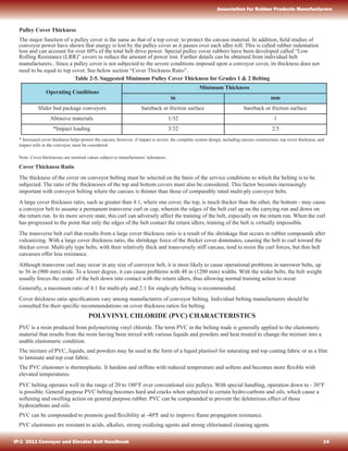
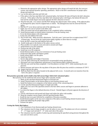
![CHAPTER 17 USEFUL TABLES
English Units SI Units
CAPACITY OF TROUGHED CONVEYOR BELTS WITH EQUAL ROLL IDLERS
Short Tons (2000 lb) per hour, TPH, with: [Metric
Tonnes, 1000 kg (2204 lb) per hour, t/h, with:] (a) Belt
speed at 100 ft per minute (0.50 m/s)
(b) Material at 100 lb per cubic ft (1600 kg/m 3)
(c) Based on edge distance, e = 0.055W + 0.9 in (20 mm)
IDLER CONVERSION FACTORS
*Surcharge angle is that angle which the material makes with the horizontal while being conveyed.
Example: Width 48 in 1200 mm
Trough Angle 45˚ 45˚ Belt
Speed 500 fpm 2.5 m/s
Material 130 lb/ft3 2080 kg/m3
Surcharge Angle 25˚ 25˚
Belt
Width
Surcharge Angle*
0˚ 5˚ 10˚ 20˚ 25˚ 30˚
in mm TPH t/h TPH t/h TPH t/h TPH t/h TPH t/h TPH t/h
14
16
18
20
24
30
36
42
48
54
60
66
72
350
400
450
500
600
750
900
1050
1200
1350
1500
1650
1800
15
21
27
34
52
86
125
175
235
300
375
455
550
13.6
19.0
25.4
30.8
47.2
78.0
113.0
159
213
272
340
413
499
18
25
33
42
63
105
155
210
280
360
450
550
655
16.3
22.7
29.9
38.1
57.2
95.3
141.0
191
254
327
408
499
594
22
29
38
49
74
120
180
250
330
420
525
640
770
20.0
26.3
34.5
44.5
67.2
109.0
164.0
227
300
381
476
581
700
28
38
50
64
96
155
230
320
425
545
680
830
995
25.4
34.5
45.4
58.2
87.2
141.0
209.0
290
386
494
617
753
902
32
43
56
72
110
176
260
360
480
610
760
930
1115
29.0
39.0
50.8
65.3
99.8
160.0
236.0
327
435
554
690
845
1011
34
48
63
80
120
195
290
400
530
680
845
1030
1230
30.8
43.6
57.2
72.5
109
177
263
363
482
617
767
935
1115
20˚ Idlers 1.00 1.000 1.00 1.00 1.00 1.00
35˚ Idlers 1.59 1.470 1.39 1.27 1.22 1.19
45˚ Idlers 1.87 1.690 1.55 1.37 1.30 1.25
Flat Rolls 0 0.185 0.32 0.53 0.56 0.62
IP:1 2011 Conveyor and Elevator Belt Handbook 130
Association for Rubber Products Manufacturers](https://image.slidesharecdn.com/arpm-manual-2-pdf-180629051921/85/Arpm-manual-2-pdf-130-320.jpg)
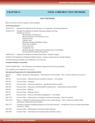
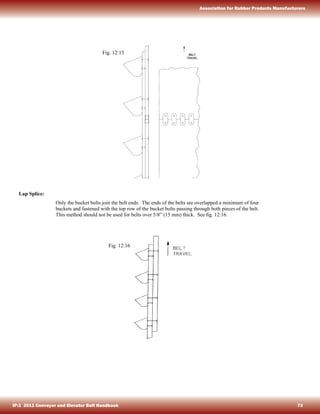
![CAPACITY OF TROUGHED CONVEYOR BELTS WITH LONG CENTER ROLL IDLERS
Short Tons (2000 lb) per hour, TPH, with: (a) Belt speed at 100 ft per minute (0.50 m/s)
[Metric Tons, 1000 kg (2204 lb) per hour, t/h, with:] (b) Material at 100 lb per cubic ft (1600 kg/m3
)
(c) Based on edge distance, e = 0.055W + 0.9 in (20 mm)
English Units SI Units
Example: Width 48 in 1200 mm
Trough Angle 45˚ LC 45˚ LC
Belt Speed 500 fpm 2.5 m/s
Material 130 lb/ft3
2080 kg/m3
Surcharge Angle 25˚ 25˚
CONVERSION FACTORS FOR CONSTANT EDGE DISTANCE
Capacity with e = 2 in (50 mm)
(Commonly used for slumping materials)
Multiply TPH (t/h) as above by the following conversion factors:
Belt Width, in
(mm)
Factors
14
(350)
0.85
16
(400)
0.91
18
(450)
0.96
20
(500)
1.0
24
(600)
1.05
30
(750)
1.095
36
(900)
1.13
42
(1050)
1.155
48
(1200)
1.175
54
(1350)
1.19
60
(1500)
1.195
66
(1600)
1.205
72
(1800)
1.215
Belt
Width
35˚ Long Center Rolls
Surcharge Angle
0˚ 5˚ 10˚ 20˚ 25˚ 30˚
in mm TPH t/h TPH t/h TPH t/h TPH t/h TPH t/h TPH t/h
24
30
36
42
48
600
750
900
1050
1200
82
105
130
150
160
74.5
95.2
118.0
136.0
145.0
95
130
165
200
220
86.2
118.0
150.0
182.0
200.0
105
145
185
225
260
95.2
132.0
168.0
204.0
236.0
110
175
235
295
355
99.9
159.0
213.0
268.0
322.0
125
195
260
330
405
113
177
236
300
368
140
210
290
370
450
127
191
263
336
408
Belt
Width
45˚ Long Center Rolls
Surcharge Angle
0˚ 5˚ 10˚ 20˚ 25˚ 30˚
in mm TPH t/h TPH t/h TPH t/h TPH t/h TPH t/h TPH t/h
24
30
36
42
48
54
60
600
750
900
1050
1200
1350
1500
97
130
160
180
200
360
390
88
118
145
163
182
327
354
110
150
190
225
260
430
485
99.9
136.0
173.0
204.0
236
390
440
115
165
210
250
295
475
540
104
150
191
227
268
432
490
130
190
255
300
380
580
680
118
172
232
272
345
526
617
140
210
280
355
430
640
755
127
191
254
322
390
582
685
150
225
305
395
485
700
830
136
204
277
358
440
635
752
IP:1 2011 Conveyor and Elevator Belt Handbook 131
Association for Rubber Products Manufacturers](https://image.slidesharecdn.com/arpm-manual-2-pdf-180629051921/85/Arpm-manual-2-pdf-131-320.jpg)


This document is an introduction to the Conveyor and Elevator Belt Handbook. It discusses the typical components of conveyor belts, including the top cover, carcass, and bottom cover. It then provides an overview of the various materials that can be used to construct these components, including different types of rubber/plastic elastomers, textiles, fibers, yarns and fabrics. Specific materials discussed include natural rubber, neoprene, nylon, polyester, cotton, glass and steel cord. The introduction explains that conveyor belts are engineered with precise specifications and standards to effectively transport various materials.


