SlideShare a Scribd company logo
1 of 103
Download to read offline
CONVEYOR

HANDBOOK


                 UPDATE June 2009

   A member of
Foreword

This “CONVEYOR HANDBOOK” is provided by FENNER DUNLOP to allow designers to select the
correct specification belting for any particular installation

Properties of fabrics used in Polyester Nylon multi-ply belting constructions are given in detail,
while the general properties and application areas of special multi-ply constructions are also
shown. Solid woven and steel cord belting are described in detail in separate sections.

The use of various natural and synthetic rubbers with these reinforcements for handling different
service conditions is set out for the designer.

Design considerations affecting power demands, belt curves, transitions etc., are provided.

The layout of this manual and its easy approach to belt design will be readily followed by belt
design engineers. Should problems arise, the services of FENNER DUNLOP are always available
to help with any problems in the design, application or operation of conveyor belts.
Index

1. Materials of construction

Reinforcements …………………………………………………………………………                 1-1
General Properties ……………………………………………………………………..             1-3


2. Belt Capacities

Capacity Calculations ………………………………………………………………….            2-1
Properties of Materials ………………………………………………………………….          2-2


3. Belt Power and Tensions

Belt Power Calculations Formulae ………………………………………………….       3-1
Calculation of Maximum Tensions ….………………………………………………..      3-5
Graduated Idler Spacings ……………………………………………………………...         3-7
Feeder Belt Calculations ……………………………………………………………….          3-9
Acceleration and Deceleration ………………………………………………………..       3 - 10
Application of Forces …………………………………………………………………..           3 - 14
Algebraic Signs of Conveyor Forces ………………………………………………..     3 - 15
Coasting …………………………………………………………………………………..                  3 - 16
Check List for Large Conveyor Systems …………………………………………...   3 - 17


4. Belt Carcass Selection

Belt Construction Requirements ………………………………………………….…        4-1
Considerations ….………………………………………………………………………                4-1
Procedure ………..………………………………………………………………………                  4-2


5. Cover Gauges and Qualities

Considerations……………………………………………………………………………                 5-1
Selection……………….…………………………………………………………………..                 5-1
Pulley side cover…………………………………………………………………………               5-1


6. Pulley Diameters

Parallel face pulleys……………………………………………………………………..           6-1
Crown face pulleys………………………………………………………………………               6-2
Pulley face width…………………………………………………………………………               6-2
7. Design Considerations

Multiple Slope and Vertical Curve Conveyors ……………………………………...   7-1
Terminal Troughing Idler Arrangements …………………………………………….        7-4
Transitions …………………………………………………………………..…………….                   7-4
Take - Up Arrangements ………………………………………………………………..               7-5


8. General Data

Belt Mass and thickness………………………..……………………………………….              8-1
Shipping dimensions and roll sizes…………………………….………………...…..      8-1
Length of belt on a roll……………………………………………………………...…...          8-2
Belt transport guidelines……………………………………………………….……….             8-3


9. Solid Woven Belting

Belt construction………………………………………………………………………….                  9-1
Belt and cover thickness………………………………………………………………..              9-2
Operating temperature range…………………………………………………………..             9-3
Operating factor of safety……………………………………………………………….             9-3
Safety……………………………………………………………………………………….                        9-2


10. Steel Cord Belting

Belt construction………………………………………………………………………...                 10 - 1
Operating conditions…………….………………………………………………..…….               10 - 2
Belt covers ……………………..…………………….………………………….……….                  10 - 5
Belt protection ……..…….………………………………………….………….……….               10 - 5
Splicing ……….….……………………………………………..…….………….……….                  10 - 6
1. Materials of construction

Reinforcements …………………………………………………………………………..                    1–1

General Properties ………………………………………………………………………                   1–3


Table 1    Reinforcement Fabrics …………………………………………………             1–2
Table 2A   Cover Compounds ……………………………………………………...               1–4
Table 2B   Heat Resistant Belts ……………………………………………………             1–5
Table 2C   Oil & Chemical Resistant ………………………………………………           1–6
Table 2D   Fire Resistant & Anti Static Belts ……………………………………..   1–7
1. Materials of construction

The composition of a conveyor belt can be considered in two parts:


A. The Carcass, whether ply type (textile) or steel cord construction, which must have sufficient
   strength to handle the operating tensions and to support the load.


B. The Covers, which must have the required physical properties and chemical resistance to
   protect the carcass and give the conveyor belt an economical life span.


The general properties and the application usage of the more economical available reinforcement
fabrics and rubber compounds are discussed in this section.


REINFORCEMENTS


Fabrics


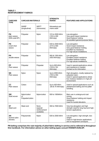
Fabrics that are commonly used as reinforcement in conveyor belts are shown in Table 1 of this
section


The fabric designation indicates the material used in both warp and weft, e.g. PN signifies that
the fabric has Polyester warp fibres and Nylon weft fibres.


The ultimate strength of the belt in kilonewtons per metre width is shown along with the number
of plies. PN1000/4 designates a belt with four plies of polyester warp, nylon weft fabric and an
ultimate full-belt tensile strength of 1000kN/m. Alternatively the belt can be often described as 4
ply PN250 where the strength of the individual plies is shown.


The allowable working tensions allocated are shown in tables 1 and 2 in section 4.


                                                                                               1-1
TABLE 1.
REINFORCEMENT FABRICS


                                                    STRENGTH
 CARCASS         CARCASS MATERIALS                  RANGE                FEATURES AND APPLICATIONS
 TYPE

                 WARP               WEFT            kilonewtons per
                 (longitudinal)     (transverse)    metre width


 PN              Polyester          Nylon           315 to 2000 kN/m     Low elongation.
 plain weave                                        (150 to 400          Very good impact resistance
 (DIN code EP)                                      kN/m/ply)            Good fastener holding
                                                                         An excellent general purpose fabric.

 PN              Polyester          Nylon           630 to 2500 kN/m     Low elongation
 crow's foot                                        (315 to 500          Good impact resistance
 weave                                              kN/m/ply)            Very good fastener holding.
                                                                         Excellent rip resistance.
                                                                         For high abuse installations

 PN              Polyester          Nylon           900 & 1350 kN/m      Low elongation.
 double weave                                       (450 kN/m/ply)       Excellent impact resistance.
                                                                         Excellent fastener holding.
                                                                         For high abuse installations.

 PP              Polyester          Polyester       Up to 900 kN/m       Used in special applications where
 Plain weave                                        (120 & 150           acid resistance is needed.
                                                    kN/m/ply)            Contact us for information.

 NN              Nylon              Nylon           Up to 2000 kN/m      High elongation, mostly replaced by
 Plain weave                                        (150 to 450          polyester-nylon.
                                                    kN/m/ply)            Used in special applications where
                                                                         low modulus needed or in high pH
                                                                         environment

 CC              Cotton             Cotton          Up to 400 kN/m       Used in special applications such as
 Plain weave                                        (65 & 70 kN/m/ply)   plasterboard belting and hot pellet
                                                                         handling.


 SW              Nylon/cotton       Nylon/cotton    600 to 1800kN/m      Main use in underground coal
 Solid woven     or                                                      mining.
                 Polyester/cotton                                        Good fastener holding and impact
                                                                         resistance.
                                                                         Used for bucket elevators.

 ST              Steel cord         None            500 to 7000 kN/m     Very low elongation and high
 Steel cord                         (special                             strength Used for long haul and high-
                                    reinforcement                        tension applications.
                                    available)

 AN              Polyaramide        Nylon           630 to 2000 kN/m     Low elongation, high strength, low-
 Aramid nylon                                                            weight.
 (Kevlar)                                                                Used on high-tension applications
                                                                         and on equipment conveyors.

PN belting comprises the vast majority of plied fabric belting in service and is referred to throughout
this handbook. For information advice on other belting types consult FENNER DUNLOP.


                                                                                                               1-2
GENERAL PROPERTIES OF
BELT COVERS AND GRADES


The following tables give a comparison of general characteristics of polymers used in belting compounds.

Special compounding can result in substantial changes to these general polymer properties.

Generally conveyor belts are supplied with electrical resistance in the anti-static range and should not be
used for electrical insulation. Special non-conductive grades are available on request.

There are four separate tables:

                                  Belts for Mining, Quarrying and General Service

                                                Heat Resistant belts

                                         Oil and Chemical Resistant grades

                                         Fire Resistant and Anti-static belts

Notes referred to in these tables are:

        1. Available with extended ozone resistance capabilities on special request.

        2. The low temperature performance figures given in the table are representative of general
            purpose compounds in each classification. Belts for operation at lower temperatures than
            those given are available on request.

        3. The high temperature performance figures given in the table are representative of situations
            where the belt is subject to relatively long exposures of blanketing heat. Considerably higher
            temperature bulk material can often be carried in ventilated situations or where the belt surface
            can be shielded to some extent by a protective layer of cooled fines.

        4. Resist most acids except concentrated strongly oxidising ie., Sulphuric, Nitric and their
            derivatives. Contact FENNER DUNLOP for specific applications.

       5. Fire resistant and anti-static grades:
          GRADE S         meets AS4606 for UNDERGROUND COAL MINING.
          GRADE E, F fire resistant and anti-static - mostly for ENCLOSED ABOVE GROUND USE
          GRADE K         fire retardant and anti-static - meets MSHA 2G and ISO433 requirements

        6. Resists most oils however resistance may vary greatly depending on the type of oil.

        7. May have poor resistance to oils with low aniline points.


                                   If in doubt, contact FENNER DUNLOP


                                                                                                         1-3
TABLE 2A – GENERAL PROPERTIES
                                                      Mining, Quarrying and General Service


   FENNER DUNLOP                                          Super M                Grade A
                              Grade M, Grade N                                                               XCG                 QuarryMaster
       GRADE                                                MA                    (SAR)
 (Common description)
                                                                             Natural Rubber            Natural Rubber
    GENERIC TYPE               Natural rubber         Natural rubber                                                            Natural Rubber
                                                                             Polybutadiene            Styrene Butadiene
     (Description)                 (NR)                   (NR)                                                                       (NR)
                                                                               (NR / BR)                  (NR / SBR)
                                                     Heavy to extreme
                             Medium to heavy duty                          Abrasion resistant for   Cut and gouge resistant   Medium to heavy duty
     APPLICATION                                     mining service with
                             mining and quarrying                             fine materials           for heavy service      mining and quarrying
                                                     lumps & abrasion

                                      M                Z – SUPER M
  AS1332 BRANDING                                                                    A                     Z – XCG            Z – QUARRYMASTER
                                      N                   Z – MA

   CO-EFFICIENT OF
                                   GOOD                    GOOD                   GOOD                      GOOD                    GOOD
   FRICTION (drive)

 WEATHERING/OZONE
                                  GOOD (1)               GOOD (1)               GOOD (1)                VERY GOOD                  GOOD (1)
    RESISTANCE

CUT/TEAR RESISTANCE          GOOD to EXCELLENT      GOOD to EXCELLENT             GOOD               GOUGE RESISTANT          GOOD to EXCELLENT

                                                       VERY GOOD /
ABRASION RESISTANCE          GOOD / VERY GOOD                                  EXCELLENT                VERY GOOD             GOOD / VERY GOOD
                                                        EXELLENT

  ACID RESISTANCE                 GOOD (4)               GOOD (4)               GOOD (4)                  GOOD (4)                 GOOD (4)


    MINERAL/OILS                   POOR                    POOR                   POOR                      POOR                    POOR

SERVICE TEMP RANGE
                                  - 30 to 70             - 30 to 70              - 30 to 70               - 30 to 70               - 30 to 70
( ºC ) See notes (2) & (3)

FLAME RESISTANCE                   POOR                    POOR                   POOR                      POOR                    POOR

                                                                                                                                                     1-4
TABLE 2B – – GENERAL PROPERTIES
                                                             TABLE 2B GENERAL PROPERTIES
                                                                   Heat resistant grades
                                                                   Heat resistant belts


   FENNER DUNLOP                     CRHR                  Apex EPT-GP                   EPT-Super                      HRNR                Hi Temp Nitrile
       GRADE
 (Common description)
    GENERIC TYPE               Styrene Butadiene        Ethylene Propylene          Ethylene Propylene              Natural rubber           Nitrile rubber
     (Description)                   (SBR)               Terpoymer (EPT)             Terpolymer (EPT)                   (NR)                     (NBR)
                                                        Heat resistant for fine
                                                                                  Maximum heat resistance       Medium heat resistance.
                             Heat resistant for lumpy         materials.
     APPLICATION                                                                  for fine materials. Resists    Resists hardening and    Oil and heat resistant
                             and abrasive materials      Resists hardening
                                                                                   hardening and cracking               cracking
                                                           and cracking

  AS1332 BRANDING                  Z – CRHR                 Z – EPT GP                Z – EPT SUPER                   Z – HRNR                Z – NITRILE

   CO-EFFICIENT OF
                                     GOOD                      GOOD                        GOOD                         GOOD                     GOOD
   FRICTION (drive)

 WEATHERING/OZONE
                                      FAIR                  EXCELLENT                   EXCELLENT                       GOOD                      FAIR
    RESISTANCE


CUT/TEAR RESISTANCE               VERY GOOD                     FAIR                        FAIR                     EXCELLENT               VERY GOOD


ABRASION RESISTANCE               VERY GOOD                    GOOD                        GOOD                         GOOD                 VERY GOOD


  ACID RESISTANCE                  GOOD (4)                 VERY GOOD                   VERY GOOD                     GOOD (4)                 GOOD (4)

                                                                                                                                            VERY GOOD to
    MINERAL/OILS                     POOR                      POOR                         POOR                        POOR
                                                                                                                                            EXCELLENT (7)

SERVICE TEMP RANGE
                                 - 10 to 125 (3)           - 20 to 170 (3)              - 20 to 210 (3)             - 20 to 100 (3)          - 10 to 125 (3)
( ºC ) See notes (2) & (3)

 FLAME RESISTANCE                    POOR                      POOR                         POOR                        POOR                     POOR

                                                                                                                                                                   1-5
TABLE 2C – GENERAL PROPERTIES
                                                                 Oil and chemical resistant grades


   FENNER DUNLOP                Hi Temp
                                               ORS Neoprene               PVC Nitrile                   SOR                  K, SOR                 EPT-GP
       GRADE                     Nitrile
 (Common description)
                                                                                                  Nitrile rubber          Nitrile rubber      Ethylene Propylene
    GENERIC TYPE              Nitrile rubber     Neoprene                  Nitrile PVC
                                                                                                Styrene Butadiene       Styrene Butadiene         Terpolymer
     (Description)                (NBR)            (CR)                   (NBR / PVC)
                                                                                                    (NBR/SBR)              (NBR / SBR)               (EPT)
                                                                     Oil resistant mostly for   Medium oil resistance     Medium oil & fire
                              Oil and heat                                                                                                    Heat, weathering and
     APPLICATION                                Oil resistant         grain handling and          mostly for grain &    resistance used for
                               resistant                                                                                                         acid resistant
                                                                      fertilizer production      wood chip handling     grain and wood chip

  AS1332 BRANDING             Z – NITRILE         Z – ORS              Z – PVC NITRILE                Z – SOR               K, Z – SOR            Z – EPT GP


   CO-EFFICIENT OF
                                 GOOD             GOOD                        FAIR                     GOOD                    FAIR                 GOOD
   FRICTION (drive)

 WEATHERING/OZONE
                                  FAIR            GOOD                   VERY GOOD                 FAIR / GOOD                 FAIR              EXCELLENT
    RESISTANCE

CUT/TEAR RESISTANCE           VERY GOOD            GOOD                      GOOD                      GOOD                   GOOD                   FAIR


ABRASION RESISTANCE           VERY GOOD            GOOD                  VERY GOOD                     GOOD                   GOOD                  GOOD


  ACID RESISTANCE              GOOD (4)          GOOD (4)                  GOOD (4)                  GOOD (4)               GOOD (4)             VERY GOOD

                             VERY GOOD TO
    MINERAL/OILS                               VERY GOOD (6)           VERY GOOD (7)                 GOOD (6)               GOOD (6)                POOR
                             EXCELLENT (7)

SERVICE TEMP RANGE
                               - 10 to 125       - 10 to 110               - 10 to 120               - 20 to 70              - 20 to 70           - 20 to 170
( ºC ) See notes (2) & (3)

 FLAME RESISTANCE                POOR             GOOD                       POOR                      POOR                   GOOD                  POOR

                                                                                                                                                                1-6
TABLE 2D – GENERAL PROPERTIES
                                                           Fire Resistant and Anti-static belts


                              Underground FRAS S,D              Grade K                   K-SOR
   FENNER DUNLOP                                                                                                                         Grade E
                             Above ground FRAS D,E,F             MSHA                 (Oil Resistant             FRAS PVC
       GRADE                                                                                                                            Anti-Static
                              Above ground FRAS K,D            Sugar FRAS               Grade K)
 (Common description)
                                                              Natural rubber
                                                                                     Nitrile rubber
    GENERIC TYPE                    Neoprene                Styrene Butadiene                                                         Natural Rubber
                                                                                   Styrene Butadiene                PVC
     (Description)                    (CR)                    Polybutadiene                                                                (NR)
                                                                                      (NBR / SBR)
                                                             (NR / SBR / BR)
                               Generally for enclosed        Sugar and grain         Medium oil & fire       Solid woven belt for
     APPLICATION             hazardous environs – coal,       industries, coal   resistance used for grain        coal mining          Grain handling
                                     grain etc.                  handling             and wood chips             underground
                             S,D     D,E,F,        K,D           K,Z - AR               K, Z - SOR                   S
  AS1332 BRANDING                                                                                                                            E
                                   (See Note 5)                (See Note 5)            (See Note 5)             (See Note 5)

   CO-EFFICIENT OF
                                      GOOD                       GOOD                     FAIR                      FAIR                  GOOD
   FRICTION (drive)

 WEATHERING/OZONE
                                   VERY GOOD                    GOOD (1)                  FAIR                      FAIR                 GOOD (1)
    RESISTANCE

CUT/TEAR RESISTANCE                VERY GOOD                     GOOD                     GOOD                      FAIR            GOOD to EXCELLENT


ABRASION RESISTANCE                EXCELLENT                  VERY GOOD                   GOOD                  VERY GOOD           GOOD / VERY GOOD


  ACID RESISTANCE                    GOOD (4)                   GOOD (4)                GOOD (4)                 GOOD (4)                GOOD (4)


    MINERAL/OILS                     GOOD (6)                    POOR                   GOOD (6)                   GOOD                   POOR

SERVICE TEMP RANGE
                                    - 10 to 100                 - 30 to 70              - 20 to 70                - 15 to 90             - 30 to 70
( ºC ) See notes (2) & (3)

 FLAME RESISTANCE                  EXCELLENT                     GOOD                     GOOD                  EXCELLENT                 POOR


                                                                                                                                                        1-7
2. Belt Capacities

Capacity Calculations ……………………………..………………………………..………….                            2–2

Properties of Materials ………………………….………………………………………………                             2–6


    Table 1   Capacity Factor – three equal roll trough idlers ………………….…          2–2
    Table 2   Cosines …………………………………...…………………………..…                               2–2
    Table 3   Capacity of Troughed Belts - three equal roll trough idlers ….….…   2–3
    Table 4   Capacity of Troughed Belts - five equal roll trough idlers ……….…    2–4
    Table 5   Maximum Lump Size Recommended for Various Belt Widths ….…           2–5
    Table 6   Typical Belt Speeds in General Use ……………………………….…                   2–5
    Table 7   Properties of Materials ……………………………..…………………..                      2–6
    Table 8   Conveyor Maximum Slope Angles …………………………………..                       2–8


                                                                                        2-1
2. Belt capacities

For maximum haulage efficiency, conveyors should be operated fully loaded at maximum recommended
speed.

Belt capacity is dependent upon these inter-related factors:

Belt width
Minimum belt width may be influenced by loading or transfer point requirements, or by material lump size
and fines mix– refer to Table 5. Troughability and load support restrictions (refer section 4), will also
influence final belt width selection

Belt speed
Possible belt speed is influenced by many factors, importantly the loading, discharge and transfer
arrangements, maintenance standards, lump sizes etc. Typical belt speeds are shown in Table 6.

Material bulk density and surcharge angle
Due to undulations of the belt passing over the conveyor idlers, the natural angle of repose of the material
is decreased. This decreased angle known as ANGLE OF SURCHARGE is one of the most important
characteristics in determining carrying capacity as it directly governs the cross sectional area of material on
the belt and hence the "volume" being conveyed.
Table 7 shows bulk density and surcharge angles for some common materials. With materials which slump
readily, such as fine powders or dust, or on long conveyors where the load may settle, consideration should
be given to using a reduced surcharge angle for capacity determination, and may require the compensatory
use of other factors (such as greater belt width or speed) to provide the required capacity.

Inclination angle
The angle of inclination of a conveyor changes the carrying capacity. The load cross-section area of an
inclined load is reduced when viewed in a vertical plane as the surcharge angle is reduced perpendicular to
the belt. An approximation of the reduced capacity can be determined by multiplying the horizontal capacity
by the Cosine of the inclination angle (see Table 2). Table 8 shows maximum inclination angle for some
common materials. Effectively the capacity reduction is usually less than 3%.

Troughing angle
For standard 3 roll idlers, the most common trough angle is 35° although trough angles from 20° to 45° are
not uncommon. Steeper trough angles give increased capacity but can have consequences for convex and
concave curves and transition zones.

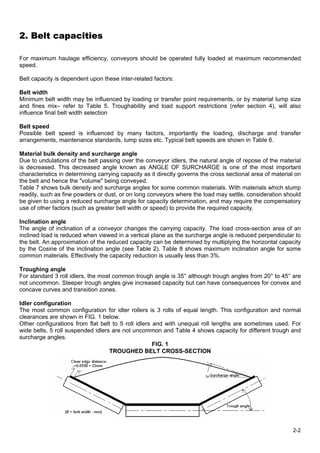
Idler configuration
The most common configuration for idler rollers is 3 rolls of equal length. This configuration and normal
clearances are shown in FIG. 1 below.
Other configurations from flat belt to 5 roll idlers and with unequal roll lengths are sometimes used. For
wide belts, 5 roll suspended idlers are not uncommon and Table 4 shows capacity for different trough and
surcharge angles.
                                                     FIG. 1
                                   TROUGHED BELT CROSS-SECTION


                                                                                                           2-2
CAPACITY CALCULATIONS

General formula:

The general formula for capacity is:

       Capacity - tonnes per hour =
       3.6 x Load Cross Section Area* (m2) x Belt Speed (m/s) x Material Density (kg/m3)………… (2.1)

       (* perpendicular to the belt)

For common idler configurations:

Capacity can be determined using the tables provided:

Table 3 of this section has been designed for quick reference and give the capacities of conveyors from
400 mm to 2200 mm wide, assuming the use of 3 roll equal length idlers at 35° troughing angle and an
average material surcharge angle of 20° and bulk density of 1000kg/m3. Capacities for conveyors using
other troughing angles or materials can be obtained by multiplying the capacity shown in Table 3 by the
appropriate CAPACITY FACTOR obtained from Table 1 below.

3 equal roll idlers:

       Capacity - tonnes per hour =
       Capacity (Table 3) x Material Density (kg/m3) x Capacity factor (Table 1) x Belt Speed (m/s) / 1000
                                                                                                      ... (2.2)

5 equal roll idlers:

       Capacity - tonnes per hour =
       Capacity (Table 4) x Material Density (kg/m3) x Belt Speed (m/s) / 1000…………………….…… (2.3)

                                             TABLE 1
                        CAPACITY FACTOR – THREE EQUAL ROLL TROUGH IDLERS


                Surcharge                             Idler troughing angle
                  angle
                                       20°          25°           30°            35°       45°
                        0°             0.43         0.53          0.61           0.69      0.81
                        5°             0.52         0.61          0.69           0.77      0.88
                       10°             0.61         0.70          0.77           0.84      0.94
                       15°             0.70         0.78          0.86           0.92      1.04
                       20°             0.79         0.87          0.94           1.00      1.08
                       25°             0.88         0.96          1.03           1.08      1.15


For inclined or declined conveyors, multiply the above by the Cosine of the inclination angle,
below:
                                           TABLE 2
                                           COSINES

        Inclination angle       0°            5°   10°      15°          17.5°    20°    22.5°    25°
             Cosine           1.000      0.996     0.985   0.966     0.954       0.940   0.924    0.906


                                                                                                           2-3
TABLE 3
                                          CAPACITY OF TROUGHED BELTS FOR
                                          THREE ROLL EQUAL LENGTH IDLERS
                                   Material bulk density: 1000 kilograms per cubic metre
                                                Surcharge angle: 20 degrees
                                                  35 degree trough angle


 Belt                                         Belt speed - metres per second
 width     0.5       0.75         1        1.25        1.5         2          2.5         3         3.5         4         4.5      5
400mm      26         39          52         65         78        104         130        156        182        209        235     261
450mm      34         51         69         86         103        137         172        206        240        274        309    343
500mm      44         65         87         109        131        175         218        262        306        349        393    437
600mm      66         99         131        164        197        263         329        394        460        526        592    657
650mm      78         118        157        196        235        314         392        471        549        628        706    785
750mm      107        161        215        268        322        429         536        644        751        858        965    1073
800mm      123        185        247        308        370        493         617        740        863        987       1110    1233
900mm      159        238        318        397        477        635         794        953       1112       1271       1430    1589
1000mm    199        298         398        497        597        795         994       1193       1392       1591       1790    1989
1050mm    221        331         441        551        662        882        1103       1323       1544       1764       1985    2206
1200mm    292        438         585        731        877       1169        1462       1754       2046       2339       2631    2923
1350mm    374        561        748        936        1123       1497        1871       2245       2619       2994       3368   3742
1400mm    404        606        807        1009       1211       1615        2019       2422       2826       3230       3634   4037
1500mm    466        699        932        1165       1398       1865        2331       2797       3263       3729       4195   4662
1600mm    533        800        1066       1333       1599       2132        2665       3198       3731       4265       4798   5331
1800mm    680        1020       1361       1701       2041       2721        3402       4082       4762       5443       6123   6803
2000mm    846        1268       1691       2114       2537       3382        4228       5073       5919       6764       7610   8455
2200mm    1029       1543       2057       2572       3086       4115        5143       6172       7201       8229       9258   10287

         For other trough and surcharge angles, multiply the above capacities by the Capacity Factor shown in Table 1.


                                                                                                                                  2-4
TABLE 4
                CAPACITY OF TROUGHED BELTS FOR
                 FIVE ROLL EQUAL LENGTH IDLERS
                    Belt speed 1.0 metre per second
         Material bulk density: 1000 kilograms per cubic metre


                    TROUGH ANGLE: 45 Degrees

 Belt                              Surcharge angle
 width        5°           10°           15°          20°         25°
1400mm       780           850           920          990        1060
1500mm       890           970          1050         1130        1210
1600mm      1010          1100          1190         1280        1370
1800mm      1270          1380          1490         1610        1730
2000mm      1560          1690          1830         1970        2120
2200mm      1920          2090          2260         2430        2610
2400mm      2320          2530          2730         2940        3150
2600mm      2770          3000          3240         3490        3740
2800mm      3240          3520          3800         4090        4380


                    TROUGH ANGLE: 55 Degrees

 Belt                              Surcharge angle
 width        5°           10°           15°          20°         25°
1400mm       870           930           990         1050        1110
1500mm       990          1060          1130         1200        1270
1600mm      1120          1200          1280         1360        1440
1800mm      1410          1510          1600         1700        1810
2000mm      1730          1850          1970         2090        2220
2200mm      2130          3600          2430         2580        2730
2400mm      2580          2750          2930         3110        3290
2600mm      3060          3270          3480         3690        3910
2800mm      3590          3830          4080         4320        4580


                    TROUGH ANGLE: 60 Degrees

 Belt                              Surcharge angle
 width        5°           10°           15°          20°         25°
1400mm       900           950          1010         1060        1120
1500mm      1020          1090          1150         1220        1280
1600mm      1160          1230          1300         1380        1450
1800mm      1460          1550          1640         1730        1820
2000mm      1790          1900          2010         2120        2240
2200mm      2210          3600          2470         2610        2750
2400mm      2660          2820          2990         3150        3320
2600mm      3170          3350          3540         3740        3940
2800mm      3710          3930          4150         4380        4610
                                                                        2-5
TABLE 5
                       MAXIMUM RECOMMENDED LUMP SIZE FOR BELT WIDTH

                Belt width           If Uniform lumps          If mixed with approx. 80% fines
                  (mm)                      (mm)                            (mm)
                   400                        75                             125
                   450                       100                             150
                   500                       100                             175
                   600                       125                             200
                   650                       125                             250
                   750                       150                             300
                   800                       150                             300
                   900                       175                             325
                  1000                       200                             375
                  1050                       200                             375
                  1200                       300                             450
                  1350                       300                             500
                  1400                       300                             600
                  1500                       350                             600
                  1600                       375                             600
                  1800                       450                             600
                  2000                       450                             600
                  2200                       475                             650


                                           TABLE 6
                    TYPICAL BELT SPEEDS IN GENERAL USE (meters per second)

         Belt width        Grain or free flowing     Run-of-mine, crushed             Hard ores and
           (mm)                 materials               coal and earth                    stone
            400                     2.0                       1.5                            -
            450                     2.5                      2.25                          1.75
            500                     3.0                      2.25                          1.75
            600                     3.0                       2.5                          2.25
            650                    3.25                      2.75                          2.50
            750                     3.5                    3.0 - 3.5                       2.75
            800                    3.75                    3.0 - 3.5                       2.75
            900                     4.0                    3.0 - 3.5                        3.0
           1000                     4.0                    3.0 - 3.5                        3.0
           1050                     4.0                    3.0 - 3.5                        3.0
           1200                     4.0                   3.25 - 4.0                     3.0 - 3.5
           1350                     4.5                   3.25 - 4.0                     3.0 - 3.5
           1400                     4.5                   3.25 - 4.0                    3.0 - 3.5
           1500                     4.5                   3.25 - 4.0                     3.0 - 3.5
           1600                     5.0                   3.75 - 4.25                   3.25 - 4.0
           1800                     5.0                   3.75 - 4.25                   3.25 - 4.0
           2000                       -                   3.75 - 4.25                   3.25 - 4.0
           2200                       -                   3.75 - 4.25                        -

NOTE: There is a world wide tendency to use increased belt speeds wherever possible. For example, brown coal is
handled at speeds over 7.5 m/s and in Australia, iron ore at speeds over 5 m/s. Such higher speeds and those shown
under run-of -mine coal, crushed coal and earth in the above table demand special attention to the design and
maintenance of loading, transfer and discharge points.


                                                                                                              2-6
PROPERTIES OF MATERIALS


Typical densities, angles of repose and surcharge angles for various materials are shown in Table 7 below.

For many materials these factors are subject to considerable variation, depending on the moisture content,
lump size, cohesive properties, etc. Unless otherwise stated, the Tables refer to dry weight conditions,
based usually on broken materials in sizes most commonly found in conveyor systems.

The physical characteristics of the material affect the operating parameters of the belt in other ways, for
example, typical belt speeds, recommended maximum lump sizes, maximum slope if the belt is inclined,
etc,. Reference is made to these factors in Tables 5, 6 & 8 of this section.

Where the material to be conveyed has unusual slumping characteristics, or where sufficient water is
present to provide lubrication between the belt cover and the material, the slope angles to be used would
be appreciably below those listed and should be determined by test or from experience in the field.

Moulded cleats can be used to raise permissible slope angles where otherwise slipping of the load on the
belt would be experienced – refer to FENNER DUNLOP for advice.


                                               TABLE 7
                                       PROPERTIES OF MATERIALS

                                                    Density          Angle of         Angle of
                       Material
                                                    (kg/m3)          repose          surcharge
        Acid phosphate                               1540               *                  *
        Alumina                                     800-960            22°                5°
        Alum - lump                                 800-960            27°                 *
        - pulverized                                720-800            35°                 *
        Ashes, boiler-house - dry, loose            560-690          38°- 45°            25
        Asphalt                                   1280-1360             *                  *
        Bagasse - fresh, moist                        120               *                25°
        - dry,loose                                    80               *                25°
        Barytes - 50-75mm lumps                   2320-2400            30°               25°
        - 15mm screenings                         2080-2320            30°               20°
        - dust                                    1760-2080            30°               15°
        Basalt - 50-75mm lumps                    1680-1760             *                25°
        - 15mm screenings                         2080-2320             *                20°
        - dust                                    1760-2080             *                15°
        Bauxite - crushed                         1200-1360          30°- 35°          5°- 15°
        Borax, solid - 50-100mm lumps              960-1040            40°                 *
        - 40-50mm lumps                             880-960          30°- 45°              *
        Brewers grain - dry                         400-480            45°                 *
        - wet                                      880-960             45°                 *
        Brick - hard                                 2000            30°- 45°              *
        - soft                                       1600            30°- 45°              *
        Carbon black - powder                          80               *                  *
        - pellets                                     400              40°                 *
        Cement, Portland - loose                  1200-1360            40°               20°
        - clinker                                 1280-1520            33°               25°
        - slurry                                     1440               *                 5°
        Chalk - 50-75mrn lumps                    1280-1360            45°                 *
        - 40-50mm lumps                           1200-1280          40°- 45°              *
        Char - sugar refinery                         720               *                  *

                                                                                                        2-7
Density      Angle of       Angle of
                Material
                                         (kg/m3)      repose        surcharge
Chips, paper mill - softwood              190-480          *           25°
- yellow pine                             320-400          *           25°
Clay - dry, loose                       1010-1440     40°- 45°       15°- 25°
- brick, ground fine                       1760           35°          15°
Coal - 150mm domestic sizes               830-900          *           25°
- run-of-mine                             720-880         35°          25°
- slack                                   690-800         37°          25°
- pulverized for coking                   480-590          *           10°
- lignite, broken                         720-880          *           25°
Cocoa                                    480-560           *             *
Coke - run of oven                        400-480         30°          25°
- breeze                                 380-560      30°- 45°         20°
Concrete, wet, on conveyor              1760-2400          *            5°
Copper ores, crushed                    2080-2400          *           25°
Copra                                       350            *             *
Corn grits                                  670            *             *
Cryolite - 50-75mrn lumps               1600-1680          *           20°
- 15mm screenings                       1440-1600          *           15°
- dust                                  1200-1440          *            5°
Dolomite - lump                         1440-1600   See limestone        *
Earth - as excavated, dry               1120-1280     30°- 45°       20°- 25°
- wet, mud                              1600-1760          *            5°
Foundry refuse, old sand, cores, etc.   960-1280           *           15°
Garbage - household                         800            *             *
Glass - batch                              1680            *             *
- broken                                1280-1600          *             *
Granite - 40-50mm lumps                 1360-1440         25°            *
- 15mm screenings                       1280-1440          *             *
- broken                                1520-1600          *             *
Gravel -dry, sharp                      1440-1600     30°- 45°         25°
- wet                                   1600-1920         32°          25°
Gutta percha                                960            *             *
Gypsum - 50-75mm lumps                  1200-1280         30°          20°
-15mm screenings                        1120-1280         40°          15°
- dust                                   960-1120         42°            *
Hops - brewery and moist                    560       30°- 45°           *
Ice - crushed                               640            *             *
Iron borings - machine shop                2000            *             *
Iron ores, depends on iron percentage   1600-3200         35°          25°
Iron pyrites - 50-75mm lumps            2160-2320          *           20°
- 15mm screenings                       1920-2160          *           15°
- dust                                  1680-1920          *            5°
Lead ores, depends on lead percentage   3200-4320         30°          15°
Limestone - 50-75mm lumps               1440-1520     30°- 40°         25°
-1 5mm screenings                       1280-1440          *           15°
- dust                                  1200-1280          *            5°
Linseed cake - crushed                   760-780           *            *
Manganese ore                           2000-2240         39°            *
Malt meal                                 570-640          *             *
Meal                                        700            *             *
Paper pulp                               640-960           *            5°
Petroleum coke                           560-640           *             *
Phosphate rock                             1360            *             *
Pitch                                      1150            *             *
Quartz, solid - 50-75mm lumps           1440-1520         35°            *
                                                                                2-8
Density    Angle of    Angle of
                 Material
                                     (kg/m3)    repose     surcharge
- 40-50mm lumps                     1360-1440     35°           *
- dust                              1120-1280     40°           *
Rock, soft, excavated with shovel   1600-1760      *          20°
Rubber                                  930        *            *
Rubber - reclaim                        560        *            *
Salt - coarse                         640-900      *          25°
- fines                                 720       25°          5°
- lump for stock                       1600        *          25°
Sand - beach or river, wet          1600-2080   15°- 30°    5°- 15°
- dry                               1440-1600   34°- 45°      15°
- foundry, loose                    1280-1440      *          15°
- foundry, rammed lumps             1600-1760      *          10°
Sandstone                           1360-1440      *            *
Sawdust                               160-200     35°           *
Shale - broken                      1440-1600      *            *
- crushed                           1360-1440     39°           *
Slag - blast furnace, crushed       1280-1440     25°         25°
- granulated, dry                    960-1040     25°         10°
-granulated, wet                    1440-1600     45°         10°
Slate - 40-75mm lumps               1360-1520      *            *
- 15mm screenings                   1280-1440     28°           *
Soda ash                             800-1040     32°           *
Sugar cane stalks                       400        *            *
Sugar - raw                          880-1040     37°           *
- refined                               880        *            *
Sulphur - 50-75mm lumps             1360-1440     35°         25°
- 15mm screenings                   1200-1360      *          15°
Talc - solid                           2640        *            *
- 50-75mm lumps                     1440-1520      *            *
- dust                              1220-1280      *            *
Turf - dry                              480        *            *
Wheat                                 720-770     28°         10°
Zinc ores, crushed                  2400-2560     38°         20°
Zinc oxide - light                    160-480      *          10°
- heavy                               480-560      *          10°


                                                                       2-9
TABLE 8
           CONVEYOR MAXIMUM SLOPE ANGLES WITH VARIOUS MATERIALS


                          Material                          Maximum slope angle
Bituminous coal - ROM                                                18°
Bituminous coal - sized                                            15°- 16°
Bituminous coal - slack                                              20°
Brown coal - ROM                                                     18°
Cement, Portland - loose                                             20°
Clay - fine and dry                                                  22°
Clay - wet lump                                                      18°
Coke - screened                                                    15°- 16°
Coke - breeze                                                        20°
Concrete - normal                                                    15°
Concrete - wet                                                     10°- 12°
Earth - loose and dry                                              18- 20°
Grains                                                               15°
Gravel - washed                                                    12°- 15°
Gravel and sand                                                    18°- 20°
Gravel and sand - wet                                              20°- 22°
Lime - powdered                                                      22°
Ores - fines only                                                    20°
Ores - mixed lumps and fines                                         18°
Ores - sized                                                         16°
Rock - fines only                                                    20°
Rock - mixed lumps and fines                                         18°
Rock - sized                                                         16°
Sand - damp                                                        18°- 20°
Sand - dry                                                           15°
Sulphur - powdered                                                   22°
Wood chips                                                         23°- 25°

For drift conveyors out of coal mines handling R.O.M. bituminous coal, slope angles of
15°- 16° are more commonly chosen than the permissible 18°.


                                                                                         2-10
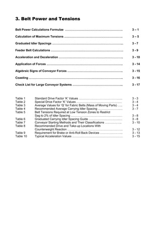
3. Belt Power and Tensions

Belt Power Calculations Formulae ………………………………………………….                           3–1

Calculation of Maximum Tensions ….……………………………………………….                           3–5

Graduated Idler Spacings ……………………………………………………………...                             3-7

Feeder Belt Calculations ……………………………………………………………….                              3-9

Acceleration and Deceleration ………………………………………………………..                           3 - 10

Application of Forces …………………………………………………………………..                               3 - 14

Algebraic Signs of Conveyor Forces ………………………………………………..                         3 - 15

Coasting …………………………………………………………………………………..                                      3 - 16

Check List for Large Conveyor Systems …………………………………………...                       3 - 17


Table 1    Standard Drive Factor ‘K’ Values ……………………………………..                    3-3
Table 2    Special Drive Factor ‘K’ Values …………………………………….…                     3-4
Table 3    Average Values for ‘Q’ for Fabric Belts (Mass of Moving Parts) …..   3-4
Table 4    Recommended Average Carrying Idler Spacing ………………….…                 3-7
Table 5    Belt Tensions Required at Low Tension Zones to Restrict
           Sag to 2% of Idler Spacing ………………………………………….…                        3-8
Table 6    Graduated Carrying Idler Spacing Guide ………………………….…                  3-8
Table 7    Conveyor Starting Methods and Their Classifications ……………..          3 - 10
Table 8    Recommended Drive and Take-up Locations With
           Counterweight Reaction ………………………………………………..                          3 - 12
Table 9    Requirement for Brake or Anti-Roll Back Devices …………………..            3 - 13
Table 10   Typical Acceleration Values ……………………………………………                        3 - 15
4. Belt Carcass Selection

Belt Construction Requirements ………………………………………………                    4-1

Considerations ….…………………………………………………………………                           4-1

Procedure ………..…………………………………………………………………                             4-2


Table 1A   Allowable Working Tensions – Standard constructions……..   4-3
Table 1B   Allowable Working Tensions – CoalMaster series…………..      4-4
Table 2A   Load support table – Standard constructions…………………        4-5
Table 2B   Load support table – CoalMaster series………………………           4-6
Table 3    Belt troughability –……………………………………………….                   4-7
4. Belt Carcass Selection


BELT CONSTRUCTION REQUIREMENTS.

To select the optimum plied belt carcass, five properties must be considered:

       ♦ The belt width.

       ♦ The service conditions under which the belt will operate.

       ♦ The maximum operating tension (Tmax) – both steady state condition and peak (see table 1).

       ♦ The minimum number of plies required to support the load (see tables 2).

       ♦ The maximum number of plies beyond which transverse flexibility is reduced and the
         troughing efficiency is affected. This varies with the belt width, trough angle and the idler roll
         arrangement (see table 3)


CONSIDERATIONS:


Operating conditions

The allowable working tensions shown on Table 1 that follow are applicable for reasonably well
maintained conveyors operating with moderate impact, infrequent starts and good loading. Peak tension
– on starting or braking, should not exceed 140% of the allowable working tension.

For more severe operating conditions, moderate maintenance, short time cycles, frequent DOL or loaded
starts, poor loading or severe impact, hot materials handling etc., reduce the tabled figures by 15%.
Tension on starting or braking should not exceed 150% of the resulting rated tension.

For severe service conditions, poor maintenance, very hot materials, chemically aggressive
environment, severe impact and short time cycles etc., reduce the tabled figures by 30%. Tension on
starting or braking should not exceed 160% of the resulting rated tension.


Safety factors

The working tensions shown on these tables are based on the application of a safety factor of 6.7:1 on
the strength of the belt at the splice or fastened join. The safety factor is increased for more difficult
operating conditions with further restrictions applying for starting and braking.


Starting and braking tensions

A check should always be made comparing the acceleration or braking tension with the allowable peak
tension for the belt, ie. 140% of rated working tension. If the peak tension exceeds the latter figure, a
stronger belt can be selected or the choice of control must be changed to reduce peak tension.


                                                  4-1
Mechanical fasteners

FENNER DUNLOP always recommend vulcanised splices for plain weave plied belting. Other
constructions including the Crows Foot Weave, Double Weave and Solid Woven PVC can be
successfully operated at close to vulcanised joint tensions for long periods of time whereas plain weave
constructions generally operate at reduced tensions when fitted with mechanical fasteners

Recommended precautions including frequent inspection and monitoring, any Local Authority restrictions
and greater than normal care should always be observed when using Mechanical Fasteners. Belt
cleaners should only be fitted if specifically suited to operation with mechanical fasteners

If a conveyor belt is to be operated for any length of time with mechanical fasteners then the selected
combination of belt and fastener should be statically tensile tested and a working tension of not more
than 15% of that result. Table 1 lists FENNER DUNLOP recommendations for its common range of belts.

Troughability and load support

This table provides a guide to the maximum width of belt that will support the load when carrying material
with the bulk density shown.
This table provides a guide to the minimum width of belt that will trough satisfactorily at the trough angle
shown. The widths shown above are a guide only and experience may dictate the selection of a ply more
or a ply less.

Some factors that may influence the choice are:

         ♦   Partially filled belt.
         ♦   Idler trough angle
         ♦   Convex or concave curve radius and idler pitch
         ♦   Lump size of material
         ♦   Installed pulley diameters

PROCEDURE:

Consider the possible belt constructions.

1.       Calculate working tension needed for the both steady state and peak (accelerating or braking).

                Required Working Tension      (kN/m)          =      Tmax (kN)
                                                                    Belt width (m)

                Where:         Tmax. = Peak or Steady State tension in conveyor (kN).

2.       Considering operating conditions and starting and braking tensions and determine suitable belt
         constructions from tables 1A and 1B. Working tensions shown in tables 1A and 1B are applicable
         for reasonably well-maintained conveyors with moderate impact, infrequent starts and good
         loading and are reduced where operating conditions are less favourable - see discussion below

3.       Consider special needs and the use of special fabrics such as Crow’s foot or Double weaves.

4.       Establish the various practical carcass/ ply number combinations to support the load for the
         conveyor working conditions under review - (Tables). Load support requirements may dictate that
         the selected belt is operating at a fraction of it’s allowable working tension.

5.       Check that the selected construction(s) are acceptable for troughing - (Table 3)

6.       Check that the installed pulley diameters are adequate – (refer section 6)

     The final selection should be checked with APEX FENNER since cost, availability and service
                           criteria can be additional factors for consideration.

                                                    4-2
Table 1A – ALLOWABLE WORKING TENSION

  Standard Constructions
  (other than CoalMaster series)

                            RECOMMENDED ALLOWABLE WORKING TENSION

     For reasonably well maintained conveyors with moderate impact, infrequent starts and good loading.

   Number of plies             2                3                4                5                6

PN 150 - 160               PN315 /2         PN500 /3         PN630 /4         PN750 /5         PN900 /6
plain weave     Spliced       24 kN/m          50 kN/m          72 kN/m          90 kN/m         112 kN/m
               Fastened       27 kN/m          40 kN/m          53 kN/m          66 kN/m          79 kN/m

PN 200 - 220               PN400 /2         PN630 /3         PN800 /4        PN1000 /5        PN1200 /6
plain weave     Spliced       30 kN/m          63 kN/m          90 kN/m         120 kN/m         150 kN/m
               Fastened       34 kN/m          51 kN/m          68 kN/m          85 kN/m         102 kN/m

PN 250                     PN500 /2         PN750 /3        PN1000 /4        PN1250 /5        PN1500 /6
plain weave     Spliced        37 kN/m          75 kN/m         112 kN/m         150 kN/m         187 kN/m
               Fastened See below        See below        See below        See below        See below

PN 300 - 315               PN630 /2         PN900 /3        PN1250 /4        PN1500 /5        PN1800 /6
plain weave     Spliced        48 kN/m          90 kN/m         140 kN/m         180 kN/m         225 kN/m
               Fastened See below        See below        See below        See below        See below

PN 320 - 350                               PN1000 /3        PN1400 /4        PN1600 /5
plain weave     Spliced                        100 kN/m         157 kN/m         192 kN/m
               Fastened                  See below        See below        See below

PN 360 - 400               PN800 /2        PN1200 /3        PN1500 /4        PN1800 /5
plain weave     Spliced        60 kN/m         120 kN/m         168 kN/m         216 kN/m
               Fastened See below        See below        See below        See below

PN 315 - 375               PN750 /2        PN1000 /3        PN1250 /4        PN1600 /5
 Crow's foot    Spliced       56 kN/m         100 kN/m         140 kN/m         192 kN/m
   weave       Fastened       56 kN/m          84 kN/m         112 kN/m         140 kN/m

PN 360 - 400               PN800 /2        PN1200 /3        PN1500 /4        PN1800 /5
 Crow's foot    Spliced       60 kN/m         120 kN/m         168 kN/m         216 kN/m
   weave       Fastened       70 kN/m         105 kN/m         140 kN/m         175 kN/m

PN 450 - 500                               PN1500 /3        PN1800 /4        PN2250 /5
 Crow's foot    Spliced                        150 kN/m         202 kN/m         270 kN/m
   weave       Fastened                  See below        See below        See below

PN 450                     PN900 /2        PN1350 /3
Double weave    Spliced      67.5 kN/m        135 kN/m
               Fastened       90 kN/m         135 kN/m

  Not generally recommended for permanent use with mechanical fasteners, but may be used with
  fasteners either temporarily or permanently under certain conditions.


                                                    4-3
Table 1B – ALLOWABLE WORKING TENSION

  CoalMaster series
  (For underground coal mining)

                           RECOMMENDED ALLOWABLE WORKING TENSION

    For reasonably well maintained conveyors with moderate impact, infrequent starts and good loading.

   Number of plies            2               3                 4                5                6

PN 150 - 160                                                PN630 /4         PN800 /5
plain weave     Spliced                                        72 kN/m          96 kN/m
               Fastened                                        53 kN/m          66 kN/m

PN 200 - 220                                                PN800 /4        PN1000 /5        PN1200 /6
plain weave     Spliced                                        90 kN/m         120 kN/m         150 kN/m
               Fastened                                        68 kN/m          85 kN/m         102 kN/m

PN 250                                                     PN1000 /4      PN1250 /5          PN1500 /6
plain weave     Spliced                                        112 kN/m       150 kN/m           187 kN/m
               Fastened                                  See below      See below          See below

PN 300 - 315                                               PN1250 /4      PN1500 /5
plain weave     Spliced                                        140 kN/m       180 kN/m
               Fastened                                  See below      See below

PN 320 - 350                                               PN1400 /4      PN1750 /5
plain weave     Spliced                                        157 kN/m       210 kN/m
               Fastened                                  See below      See below

PN 360 - 400                                               PN1600 /4      PN2000 /5
plain weave     Spliced                                        180 kN/m       240 kN/m
               Fastened                                  See below      See below

PN 315 - 375                              PN1120 /3        PN1400 /4        PN1600 /5
 Crow's foot    Spliced                      100 kN/m         157 kN/m         192 kN/m
   weave       Fastened                       90 kN/m         115 kN/m         140 kN/m

PN 360 - 400                              PN1200 /3        PN1600 /4        PN1875 /5
 Crow's foot    Spliced                      120 kN/m         180 kN/m         225 kN/m
   weave       Fastened                      105 kN/m         140 kN/m         175 kN/m

PN 450 - 500                              PN1500 /3        PN2000 /4      PN2500 /5
 Crow's foot    Spliced                       150 kN/m         225 kN/m       300 kN/m
   weave       Fastened                 See below        See below      See below

PN 450                                    PN1350 /3
Double weave    Spliced                      135 kN/m
               Fastened                      135 kN/m


  Not generally recommended for permanent use with mechanical fasteners, but may be used
  with fasteners either temporarily or permanently under certain conditions.


                                                   4-4
Table 2A - LOAD SUPPORT

Plain Weave Fabrics
(with standard thickness skim)

                                 MAXIMUM WIDTH TO SUPPORT THE LOAD

                                   For conventional troughed conveyors

     Number of plies              2             3               4             5           6

PN 150 - 160                PN315 /2        PN500 /3       PN630 /4       PN750 /5    PN900 /6
 plain weave 800 kg/m3        900 mm         1100 mm        1600 mm        2100 mm     2500 mm
    Load      1200 kg/m3      700 mm         1000 mm        1500 mm        1900 mm     2400 mm
Bulk density: 1800 kg/m3      600 mm          800 mm        1300 mm        1700 mm     2200 mm
              2600 kg/m3        -             500 mm        1000 mm        1500 mm     1900 mm

PN 200 - 220                PN400 /2        PN630 /3       PN800 /4      PN1000 /5   PN1200 /6
 plain weave 800 kg/m3       1100 mm         1300 mm        1800 mm        2400 mm        -
    Load      1200 kg/m3     1000 mm         1200 mm        1700 mm        2300 mm        -
Bulk density: 1800 kg/m3      800 mm         1000 mm        1500 mm        2100 mm        -
              2600 kg/m3      500 mm          800 mm        1300 mm        1800 mm     2300 mm

PN      250                 PN500 /2        PN750 /3      PN1000 /4      PN1250 /5   PN1500 /6
 plain weave 800 kg/m3       1200 mm         1500 mm        2100 mm           - mm        -
    Load      1200 kg/m3     1100 mm         1400 mm        2000 mm           - mm        -
Bulk density: 1800 kg/m3      900 mm         1200 mm        1800 mm        2500 mm        -
              2600 kg/m3      700 mm         1100 mm        1600 mm        2200 mm        -

PN 300 - 315                PN630 /2        PN900 /3      PN1250 /4      PN1500 /5   PN1800 /6
 plain weave 800 kg/m3       1400 mm         1800 mm           - mm           -           -
    Load      1200 kg/m3     1300 mm         1600 mm        2500 mm           -           -
Bulk density: 1800 kg/m3     1100 mm         1500 mm        2300 mm           -           -
              2600 kg/m3      800 mm         1200 mm        2100 mm           -           -

PN 320 - 350                               PN1000 /3      PN1400 /4      PN1600 /5
 plain weave 800 kg/m3                       2000 mm           -              -
    Load      1200 kg/m3                     1800 mm           -              -
Bulk density: 1800 kg/m3                     1600 mm        2400 mm           -
              2600 kg/m3                     1400 mm        2200 mm           -

PN 360 - 400                PN800 /2       PN1200 /3      PN1500 /4      PN1800 /5
 plain weave 800 kg/m3       1600 mm         2100 mm        2400 mm           -
    Load      1200 kg/m3     1500 mm         2000 mm           -              -
Bulk density: 1800 kg/m3     1300 mm         1800 mm           -              -
              2600 kg/m3     1000 mm         1600 mm           -              -


                                                  4-5
Table 2B - LOAD SUPPORT

Special Weave Fabrics
(with standard thickness skim)

                                 MAXIMUM WIDTH TO SUPPORT THE LOAD

                                   For conventional troughed conveyors

     Number of plies              2             3               4            5       6

PN 315 - 375                PN750 /2       PN1000 /3       PN1250 /4     PN1600 /5
 Crow's foot   800 kg/m3     1600 mm         2100 mm            -             -
   weave      1200 kg/m3     1500 mm         2000 mm            -             -
Bulk density: 1800 kg/m3     1300 mm         1800 mm            -             -
              2600 kg/m3     1000 mm         1600 mm         2400 mm          -

PN 360 - 400                PN800 /2       PN1200 /3       PN1500 /4     PN1800 /5
 Crow's foot   800 kg/m3     1700 mm         2400 mm            -             -
   weave      1200 kg/m3     1600 mm         2200 mm            -             -
Bulk density: 1800 kg/m3     1400 mm         2000 mm            -             -
              2600 kg/m3     1200 mm         1800 mm            -             -

PN 450 - 500                               PN1500 /3       PN1800 /4     PN2250 /5
 Crow's foot   800 kg/m3                        -               -             -
   weave      1200 kg/m3                        -               -             -
Bulk density: 1800 kg/m3                     2400 mm            -             -
              2600 kg/m3                     2200 mm            -             -

PN 450                      PN900 /2       PN1350 /3
Double weave   800 kg/m3     1900 mm            -
              1200 kg/m3     1800 mm            -
Bulk density: 1800 kg/m3     1600 mm            -
              2600 kg/m3     1300 mm            -


                                                  4-6
Table 3 – TROUGHABILITY

Plain Weave Fabrics
(with standard thickness skim)

                                 MINIMUM WIDTH TO TROUGH THE BELT
                                  (For conventional troughed conveyors)

    Number of plies              2             3               4             5           6

 PN 150 - 160               PN315 /2        PN500 /3       PN630 /4       PN750 /5    PN900 /6
 plain weave 20 to 30º          -             400 mm         450 mm         500 mm      600 mm
              30 to 40º         -             450 mm         500 mm         600 mm      750 mm
              up to 45º       400 mm          500 mm         600 mm         650 mm      800 mm

 PN 200 - 220               PN400 /2        PN630 /3       PN800 /4       PN1000 /5   PN1200 /6
 plain weave 20 to 30º            mm          450 mm         500 mm          650 mm      800 mm
              30 to 40º       450 mm          500 mm         650 mm          750 mm      900 mm
              up to 45º       500 mm          650 mm         800 mm          900 mm     1050 mm

 PN 250                     PN500 /2        PN750 /3      PN1000 /4       PN1250 /5   PN1500 /6
 plain weave   20 to 30º      400 mm          450 mm         650 mm          800 mm      900 mm
               30 to 40º      450 mm          600 mm         800 mm          900 mm     1000 mm
               up to 45º      600 mm          750 mm         900 mm         1050 mm     1350 mm

 PN 300 - 315               PN630 /2        PN900 /3      PN1250 /4       PN1500 /5   PN1800 /6
 plain weave 20 to 30º        400 mm          600 mm         750 mm          800 mm     1000 mm
              30 to 40º       500 mm          650 mm         800 mm          900 mm     1050 mm
              up to 45º       600 mm          800 mm        1000 mm         1050 mm     1200 mm

 PN 320 - 350                              PN1000 /3      PN1400 /4       PN1600 /5
 plain weave 20 to 30º                        600 mm         750 mm          900 mm
              30 to 40º                       750 mm         900 mm         1050 mm
              up to 45º                       800 mm        1000 mm         1200 mm

 PN 360 - 400               PN800 /2       PN1200 /3      PN1500 /4       PN1800 /5
 plain weave 20 to 30º        500 mm          650 mm         800 mm         1050 mm
              30 to 40º       600 mm          750 mm         900 mm         1200 mm
              up to 45º       650 mm          900 mm        1050 mm         1400 mm

 PN 315 - 375               PN750 /2       PN1000 /3      PN1250 /4       PN1600 /5
  Crow's foot 20 to 30º       500 mm          650 mm         750 mm          900 mm
    weave     30 to 40º       600 mm          750 mm         900 mm         1050 mm
              up to 45º       750 mm          900 mm        1050 mm         1350 mm

 PN 360 - 400               PN800 /2       PN1200 /3      PN1500 /4       PN1800 /5
  Crow's foot 20 to 30º       500 mm          650 mm         800 mm         1050 mm
    weave     30 to 40º       650 mm          750 mm         900 mm         1200 mm
              up to 45º       750 mm          900 mm        1050 mm         1500 mm

 PN 450 - 500                              PN1500 /3      PN1800 /4       PN2250 /5
  Crow's foot 20 to 30º                       900 mm        1050 mm         1200 mm
    weave     30 to 40º                      1050 mm        1200 mm         1400 mm
              up to 45º                      1200 mm        1400 mm         1600 mm

PN 450                      PN900 /2       PN1350 /3
Double weave 20 to 30º        650 mm          900 mm
             30 to 40º        750 mm         1000 mm
             up to 45º        900 mm         1200 mm


                                                   4-7
5. Cover Gauges and Qualities

Considerations…………………………………………………………………….          5-1

Selection……………….……………………………………………………………            5-1

Pulley side cover………………………………………………………………….        5-1


Table 1 Top Cover Thickness ……………………………………………………   5–2
5. Cover gauges and qualities


CONSIDERATIONS


There are a number of factors that must be taken into account when selecting the belt grade or cover
material, such as:

       ♦   Fire resistance or anti-static properties
       ♦   Resistance to oils or chemicals
       ♦   Temperature of the operating environment or conveyed material
       ♦   Resistance to ageing, weathering and ozone.
       ♦   The type of material being conveyed
       ♦   The lump size and shape of the material being conveyed
       ♦   The mix of lumps and fines in the material
       ♦   The abrasiveness of the material
       ♦   The method of loading the belt
       ♦   The fall height of material to the belt
       ♦   The cycle time of the conveyor for a single revolution of the belt
       ♦   Performance or experience in a similar application
       ♦   For replacement belts – the performance of previous belts on the same installation
       ♦   Availability and cost


SELECTION

Previous experience will always be the best guide to the optimum selection of both the type and
thickness of belt cover, however if this information is not available as will be the case for new
installations, the following steps should be followed.

       ♦ From table 1 – 2 select the most suitable cover types of cover or belt grades for the
         application. In some cases statutory requirements or the operating conditions will limit
         selections to one or two possibilities.
       ♦ Calculate the time cycle of the conveyor = (2 x L)
                                                       S
                                                          Where: L = conveyor centres (m)
                                                          S = belt speed (m/s)

       ♦ Use table 1 as a guide to select the appropriate thickness of top cover. Consideration should
         be given to the applicable properties of the cover in making this selection.

For difficult applications such as belt feeders, or impact belts, heavier covers may be required.


PULLEY SIDE COVER

As a guide, pulley side cover should generally be not less than 1/4 of carry side cover for covers up to
9mm and about 1/3 of carry cover thickness for covers heavier than 9mm. Operating conditions can
dictate that heavier pulley side covers are required.
For long centre, long time cycle conveyors, pulley side cover can be up to 1/2 of carry side cover.


                                                    5-1
TABLE 1
BELT COVER THICKNESS


                               Lightly abrasive                       Moderately abrasive                        Heavily abrasive                        Extremely abrasive
    Time cycle                    materials                               materials                                 materials                                 materials
     seconds

      (2 x L)
         S
                                    Lump size                                 Lump size                                Lump size                                Lump size
   Cycle time for                     (mm)                                      (mm)                                     (mm)                                     (mm)
   complete belt
    revolution.
                      10      50      125       200    300      10      50      125       200   300      10      50      125       200    300    10       50       125      200      300


   15 seconds         1-2     3-5      6-7    8-10    10-12    1-2      4-5     7-10    9-12    11-15    2-4     4-7     7-10   10-15 12-19      3-6     4-10     8-15     10-19 13-23


   30 seconds         1-2     3-4      5-6      6-8   8-10     1-2      3-4      5-8    7-10    9-12     2-3     3-6     6-10    8-12    10-15   2-5      4-8     6-12     8-15     10-18


   60 seconds         1-2     2-3      4-5      5-6    7-8     1-2      3-4      5-6      6-8   7-10     1-3     3-5      5-8    6-10    8-13    2-4      3-6     5-10     7-13     9-15


   120 seconds        1-2     2-3      3-4      5-6    6-7     1-2      2-3      4-6      5-7    6-9     1-2     2-4      4-7      6-9   7-11    2-4      3-6      5-7     6-11     8-13


   180 seconds
                      1-2     1-2      3-4      4-5    5-6     1-2      2-3      4-5      5-6    6-8     1-2     2-4      4-6      5-8   6-10    2-3      2-5      4-8     5-10     7-12
     and over

                     Wood chips - bituminous coal - grains - Basalt - sand - anthracite coal - crushed   Limestone - ores - phosphate - slag -
 Typical materials                                                                                                                               Glass cullet - granite - quartz ores etc.
                            round river gravel etc.                         gravel etc.                          cement clinker etc.
6. Pulley Diameters

Parallel face pulleys…………………………………………………………………….. 6 - 1

Crown face pulleys……………………………………………………………………… 6 - 2

Pulley face width………………………………………………………………………… 6 - 2


Table 1A       Standard constructions
        – operating at over 60% of allowable working tension ………………    6-3
Table 1B       CoalMaster series
        – operating at over 60% of allowable working tension ………………    6-4
Table 2A       Standard constructions
        – operating at 30 - 60% of allowable working tension ….……………   6-5
Table 2B       CoalMaster series
        – operating at 30 - 60% of allowable working tension …….…………   6-6
6. Pulley diameters


   The minimum pulley diameter recommended for a particular belt depends upon three factors:

        •         Carcass Thickness – The wire rope diameter in the case of Steel Cord belts.
                                    – The overall thickness of all plies plus the rubber skims
                                    between plies in the case of Ply Type belts.
                                    – The overall thickness of the thick woven fabric separating
                                    the top and bottom covers in the case of Solid-woven belts.

        •         Operating Tension     – The relationship of the operating tension of the belt at the
                                        particular pulley to the belt’s Allowable Working Tension.

        •         Carcass modulus       – The relationship between elongation of the carcass and
                                        the resulting stress.

   Whatever the carcass type, Steel Cord, Ply Type or Solid Woven, when the belt is bent around a
   small radius, tension stresses are developed in the outer fibres while compression stresses are built
   up in the inner fibres. At a given tension, if the radius is too small the elastic limit of the outer fibres
   may be exceeded and fracture, and at the same time, the compression of the inner fibres may cause
   severe crinkling and eventual ply separation.

   Since the elastic properties of the rubber or PVC cover material is so much greater than the carcass
   material, the cover thickness of the belting is not a factor in determining minimum pulley size, and
   may be ignored.

   The tables of recommended pulley diameters in the FENNER DUNLOP handbook for Ply Type
   belting are based on the three classes of pulleys defined in ISO 3684. viz.;

    •       Type “A” – High tension / tight side pulleys (T1) e.g. head, drive, tripper and shuttle pulleys
    •       Type “B” – Low tension or slack side pulleys (T2) such as tail and take up pulleys
    •       Type “C" – Low tension snub or bend pulleys with wrap angle of less than 30 degrees

Two sets of Pulley Diameter tables follow:

    •       For belts operating at over 60% of allowable working tension
                     Table 1 A - for standard belt constructions
                     Table 1 B – for CoalMaster series belts

    •       For belts operating at 30 – 60% of allowable working tension
                     Table 2 A - for standard belt constructions
                     Table 2 B – for CoalMaster series belts

For belts operating at less than 30% of the allowable working tension, the diameter of Type “A”
pulleys can be reduced to the same as Type “B”.


PARALLEL FACE PULLEYS

With just a few special exceptions, all pulleys used with modern high strength, high modulus fabric
belts should be parallel face types. It is absolutely mandatory that all pulleys used in conveyors fitted
with Steel Cord belting be parallel face type. One notable exception to this rule is in the case of
Bucket Elevators which, lacking any other means of tracking the belt centrally, may benefit from
Crown Faced Pulleys.

                                                      6-1
CROWN FACE PULLEYS

A Crown Faced pulley can have the effect of centering the tracking of the belt, but only in the case
where there is a long unsupported length of belt leading into the pulley, as the belt must be able to
bend longitudinally along its centreline to benefit from the crown. High modulus Ply Type belts have
very little ability to bend longitudinally and Steel Cord belts have virtually no ability at all. Solid Woven
belts are not quite so rigid but still need an unsupported distance of something like 4 to 6 times the
belt width to be able to react.

Apart from not serving much purpose in troughed conveyor systems, Crowned pulleys can seriously
damage the belt by severely overstressing the carcass in the centre of the belt, particularly in the case
of Steel Cord belts.

The few special cases where Crowned pulleys are useful include, Bucket Elevators, the Take- up
pulley in long gravity Take-up arrangements and for some short centre - wide belt, reversing
conveyors. In cases like this where there are no supporting idlers to train the belt, some benefit may
be obtained from the installation of Crowned pulleys.

                                Face Width W
                                                                                  Taper
                                                                                  1 in 100


                        W/4                                W/4
                                        W/2


                                                                        d     D


It is fairly common practice to crown a pulley by machining a taper of 1 in 100 from each pulley edge
towards the centre over a distance of 1/4 pulley face. It is more correct to relate the amount of pulley
crown to the pulley diameter, not to its face width. Viz.; d = D - 0.008 x D


PULLEY FACE WIDTH

As all belts tend to wander a bit in operation, the overall face width of the pulleys should exceed the
belt width by the following minimum amounts, if serious edge damage is to be avoided;

    •             Belts up to 650mm wide …. …. …. …. …. …. …. …. 100mm
    •             Belts 750 to 1400mm wide …. …. …. …. …. …. …. …. 150mm
    •             Belts over 1400mm wide …. …. …. …. …. …. …. …. 200mm

For conveyors built on unstable ground, as in underground coal mines and very long overland
conveyors, the above allowances should be increased by 50mm.


                                                  6-2
TABLE 1A
  STANDARD CONSTRUCTIONS
  (other than CoalMaster series)

                           RECOMMENDED MINIMUM PULLEY DIAMETERS

                For belts operating at over 60% of maximum allowable working tension

     Number of plies            2              3              4               5           6

PN 150 - 160                 PN315 /2       PN500 /3        PN630 /4       PN750 /5    PN900    /6
 plain weave    Type “A”       315 mm         400 mm          560 mm         710 mm      800    mm
                Type “B”       250 mm         315 mm          450 mm         560 mm      630    mm
                Type “C”       200 mm         250 mm          360 mm         450 mm      500    mm

PN 200 - 220                 PN400 /2       PN630 /3        PN800 /4      PN1000 /5    PN1200 /6
 plain weave    Type “A”       400 mm         450 mm          630 mm         800 mm       900 mm
                Type “B”       315 mm         360 mm          500 mm         630 mm       710 mm
                Type “C”       250 mm         280 mm          400 mm         500 mm       560 mm

PN 250                       PN500 /2       PN750 /3      PN1000 /4       PN1250 /5    PN1500   /6
 plain weave    Type “A”       450 mm         500 mm         710 mm          900 mm      1120   mm
                Type “B”       360 mm         400 mm         560 mm          710 mm       900   mm
                Type “C”       280 mm         315 mm         450 mm          560 mm       710   mm

PN 300 - 315                 PN630 /2       PN900 /3      PN1250 /4       PN1500 /5    PN1800   /6
 plain weave    Type “A”       500 mm         560 mm         800 mm         1120 mm      1400   mm
                Type “B”       400 mm         450 mm         630 mm          900 mm      1120   mm
                Type “C”       315 mm         360 mm         500 mm          710 mm       900   mm

PN 320 - 350                               PN1000 /3      PN1400 /4       PN1600 /5
 plain weave    Type “A”                      630 mm         900 mm         1120 mm
                Type “B”                      500 mm         710 mm          900 mm
                Type “C”                      400 mm         560 mm          710 mm

PN 360 - 400                 PN800 /2      PN1200 /3      PN1500 /4       PN1800 /5
 plain weave    Type “A”       560 mm         710 mm        1000 mm         1250 mm
                Type “B”       450 mm         560 mm         800 mm         1000 mm
                Type “C”       360 mm         450 mm         630 mm          800 mm

PN 315 - 375                 PN750 /2      PN1000 /3      PN1250 /4       PN1600 /5
 Crow's foot    Type “A”       560 mm         710 mm        1000 mm         1250 mm
    weave       Type “B”       450 mm         560 mm         800 mm         1000 mm
                Type “C”       360 mm         450 mm         630 mm          800 mm

PN 360 - 400                 PN800 /2      PN1200 /3      PN1500 /4       PN1800 /5
 Crow's foot    Type “A”       560 mm         800 mm        1000 mm         1250 mm
    weave       Type “B”       450 mm         630 mm         800 mm         1000 mm
                Type “C”       360 mm         500 mm         630 mm          800 mm

PN 450 - 500                               PN1500 /3      PN1800 /4       PN2250 /5
 Crow's foot    Type “A”                      900 mm        1250 mm         1600 mm
    weave       Type “B”                      710 mm        1000 mm         1250 mm
                Type “C”                      560 mm         800 mm         1000 mm

PN 450                       PN900 /2      PN1350 /3
Double weave    Type “A”       630 mm        1000 mm
                Type “B”       500 mm         800 mm
                Type “C”       400 mm         630 mm


                                               6-3
Essential Conveyor Belt Handbook

More Related Content

What's hot (20)

Conveyor system
Conveyor systemConveyor system
Conveyor system
 
Arpm manual-2-pdf
Arpm manual-2-pdfArpm manual-2-pdf
Arpm manual-2-pdf
 
Design and fabrication_automatic_conveyor_ppt
Design and fabrication_automatic_conveyor_pptDesign and fabrication_automatic_conveyor_ppt
Design and fabrication_automatic_conveyor_ppt
 
Belt conveyor
Belt conveyorBelt conveyor
Belt conveyor
 
Belt Conveyor System
Belt Conveyor SystemBelt Conveyor System
Belt Conveyor System
 
Belt conveyor
Belt conveyorBelt conveyor
Belt conveyor
 
Conveyor belts new1(final)x
Conveyor belts new1(final)xConveyor belts new1(final)x
Conveyor belts new1(final)x
 
Belt drive
Belt driveBelt drive
Belt drive
 
Design of Belt conveyor system
 Design of Belt conveyor system Design of Belt conveyor system
Design of Belt conveyor system
 
Components of Belt conveyor
Components of Belt conveyorComponents of Belt conveyor
Components of Belt conveyor
 
Belt conveyor and its type
Belt conveyor and its typeBelt conveyor and its type
Belt conveyor and its type
 
Belt conveyor
Belt conveyorBelt conveyor
Belt conveyor
 
Lesson 14-idlers-and-pulleys
Lesson 14-idlers-and-pulleysLesson 14-idlers-and-pulleys
Lesson 14-idlers-and-pulleys
 
Vibrating feeder
Vibrating feederVibrating feeder
Vibrating feeder
 
Chapter 2 Conveyor System.pptx
Chapter 2 Conveyor System.pptxChapter 2 Conveyor System.pptx
Chapter 2 Conveyor System.pptx
 
Belt conveyor
Belt conveyorBelt conveyor
Belt conveyor
 
Belt Tracking & Conveyor Maintenance
Belt Tracking & Conveyor MaintenanceBelt Tracking & Conveyor Maintenance
Belt Tracking & Conveyor Maintenance
 
conveyor.pptx
conveyor.pptxconveyor.pptx
conveyor.pptx
 
Conveyor Belts
Conveyor BeltsConveyor Belts
Conveyor Belts
 
Belt conveyor
Belt conveyorBelt conveyor
Belt conveyor
 

Viewers also liked

Bulk Materials conveyors| Materials Handling Conveyors manufacturer | Neo con...
Bulk Materials conveyors| Materials Handling Conveyors manufacturer | Neo con...Bulk Materials conveyors| Materials Handling Conveyors manufacturer | Neo con...
Bulk Materials conveyors| Materials Handling Conveyors manufacturer | Neo con...Neo Conveyors
 
Ancillary Hydraulic Devices, dr.samir elshamy
Ancillary Hydraulic Devices, dr.samir elshamyAncillary Hydraulic Devices, dr.samir elshamy
Ancillary Hydraulic Devices, dr.samir elshamyDr.Samir el-shamy
 
Conveyor Belt Guarding as Metal and Nonmetal Mines
Conveyor Belt Guarding as Metal and Nonmetal MinesConveyor Belt Guarding as Metal and Nonmetal Mines
Conveyor Belt Guarding as Metal and Nonmetal Minescccscoetc
 
Festo electro hydraulics basic levels-textbook
Festo electro hydraulics basic levels-textbookFesto electro hydraulics basic levels-textbook
Festo electro hydraulics basic levels-textbookGanaa Ganbat
 
Basic hydraulics
Basic hydraulicsBasic hydraulics
Basic hydraulicsPINAKI ROY
 
Material Handling in Port
Material Handling in PortMaterial Handling in Port
Material Handling in PortRanjan Mohanty
 

Viewers also liked (9)

Bulk Materials conveyors| Materials Handling Conveyors manufacturer | Neo con...
Bulk Materials conveyors| Materials Handling Conveyors manufacturer | Neo con...Bulk Materials conveyors| Materials Handling Conveyors manufacturer | Neo con...
Bulk Materials conveyors| Materials Handling Conveyors manufacturer | Neo con...
 
Ancillary Hydraulic Devices, dr.samir elshamy
Ancillary Hydraulic Devices, dr.samir elshamyAncillary Hydraulic Devices, dr.samir elshamy
Ancillary Hydraulic Devices, dr.samir elshamy
 
Conveyor Belt Guarding as Metal and Nonmetal Mines
Conveyor Belt Guarding as Metal and Nonmetal MinesConveyor Belt Guarding as Metal and Nonmetal Mines
Conveyor Belt Guarding as Metal and Nonmetal Mines
 
Sany mining equipment series
Sany mining equipment seriesSany mining equipment series
Sany mining equipment series
 
Festo electro hydraulics basic levels-textbook
Festo electro hydraulics basic levels-textbookFesto electro hydraulics basic levels-textbook
Festo electro hydraulics basic levels-textbook
 
Basic hydraulics
Basic hydraulicsBasic hydraulics
Basic hydraulics
 
Conveyors
ConveyorsConveyors
Conveyors
 
conveyor belt
conveyor beltconveyor belt
conveyor belt
 
Material Handling in Port
Material Handling in PortMaterial Handling in Port
Material Handling in Port
 

Similar to Essential Conveyor Belt Handbook

Conveyor handbook-pdf
Conveyor handbook-pdfConveyor handbook-pdf
Conveyor handbook-pdfmkpq pasha
 
Welcome to International Journal of Engineering Research and Development (IJERD)
Welcome to International Journal of Engineering Research and Development (IJERD)Welcome to International Journal of Engineering Research and Development (IJERD)
Welcome to International Journal of Engineering Research and Development (IJERD)IJERD Editor
 
Mg041911 Cortland Lifting Slings Presentation
Mg041911 Cortland Lifting Slings PresentationMg041911 Cortland Lifting Slings Presentation
Mg041911 Cortland Lifting Slings Presentationrarends
 
133822290 conveyor-belt
133822290 conveyor-belt133822290 conveyor-belt
133822290 conveyor-beltestiakkaosae
 
TYRE CORD PROCESSING.pptx
TYRE CORD PROCESSING.pptxTYRE CORD PROCESSING.pptx
TYRE CORD PROCESSING.pptxSnehaa82
 
Double_Braid_Inspection_and_Retirement
Double_Braid_Inspection_and_RetirementDouble_Braid_Inspection_and_Retirement
Double_Braid_Inspection_and_RetirementJeffery Flower
 
Experimental Study of the Flexural Behaviour of Damaged RC Beams Strengthened...
Experimental Study of the Flexural Behaviour of Damaged RC Beams Strengthened...Experimental Study of the Flexural Behaviour of Damaged RC Beams Strengthened...
Experimental Study of the Flexural Behaviour of Damaged RC Beams Strengthened...IJERA Editor
 
Steel fibers for reinforced concrete kasturi metal
Steel fibers for reinforced concrete   kasturi metalSteel fibers for reinforced concrete   kasturi metal
Steel fibers for reinforced concrete kasturi metalKasturi Metal
 
IRJET- Experimental Study on Retrofitted RC- Beams
IRJET- Experimental Study on Retrofitted RC- BeamsIRJET- Experimental Study on Retrofitted RC- Beams
IRJET- Experimental Study on Retrofitted RC- BeamsIRJET Journal
 
Dref iii polyester-wool blended friction-spun yarn
Dref iii polyester-wool blended friction-spun yarnDref iii polyester-wool blended friction-spun yarn
Dref iii polyester-wool blended friction-spun yarnNiloy Rahman
 
properties and application of technical textile fibers
properties and application of technical textile fibersproperties and application of technical textile fibers
properties and application of technical textile fibersShahriar Shovon
 
Cnt reinforced basalt fiber based ship hulls
Cnt reinforced basalt fiber based ship hullsCnt reinforced basalt fiber based ship hulls
Cnt reinforced basalt fiber based ship hullseSAT Publishing House
 
IRJET- Analysis of FRP in Strengthened RC Columns
IRJET- Analysis of FRP in Strengthened RC ColumnsIRJET- Analysis of FRP in Strengthened RC Columns
IRJET- Analysis of FRP in Strengthened RC ColumnsIRJET Journal
 
FIBER REINFORCED POLYMER CONCRETE
FIBER REINFORCED POLYMER CONCRETEFIBER REINFORCED POLYMER CONCRETE
FIBER REINFORCED POLYMER CONCRETEARCHITECTURE SCHOOL
 

Similar to Essential Conveyor Belt Handbook (20)

Conveyor handbook-pdf
Conveyor handbook-pdfConveyor handbook-pdf
Conveyor handbook-pdf
 
Wire rope design
Wire rope design Wire rope design
Wire rope design
 
Welcome to International Journal of Engineering Research and Development (IJERD)
Welcome to International Journal of Engineering Research and Development (IJERD)Welcome to International Journal of Engineering Research and Development (IJERD)
Welcome to International Journal of Engineering Research and Development (IJERD)
 
Instron machine
Instron machineInstron machine
Instron machine
 
Mg041911 Cortland Lifting Slings Presentation
Mg041911 Cortland Lifting Slings PresentationMg041911 Cortland Lifting Slings Presentation
Mg041911 Cortland Lifting Slings Presentation
 
133822290 conveyor-belt
133822290 conveyor-belt133822290 conveyor-belt
133822290 conveyor-belt
 
TYRE CORD PROCESSING.pptx
TYRE CORD PROCESSING.pptxTYRE CORD PROCESSING.pptx
TYRE CORD PROCESSING.pptx
 
Double_Braid_Inspection_and_Retirement
Double_Braid_Inspection_and_RetirementDouble_Braid_Inspection_and_Retirement
Double_Braid_Inspection_and_Retirement
 
Experimental Study of the Flexural Behaviour of Damaged RC Beams Strengthened...
Experimental Study of the Flexural Behaviour of Damaged RC Beams Strengthened...Experimental Study of the Flexural Behaviour of Damaged RC Beams Strengthened...
Experimental Study of the Flexural Behaviour of Damaged RC Beams Strengthened...
 
Steel fibers for reinforced concrete kasturi metal
Steel fibers for reinforced concrete   kasturi metalSteel fibers for reinforced concrete   kasturi metal
Steel fibers for reinforced concrete kasturi metal
 
ROJIN.pdf
ROJIN.pdfROJIN.pdf
ROJIN.pdf
 
IRJET- Experimental Study on Retrofitted RC- Beams
IRJET- Experimental Study on Retrofitted RC- BeamsIRJET- Experimental Study on Retrofitted RC- Beams
IRJET- Experimental Study on Retrofitted RC- Beams
 
Lecture 13
Lecture 13Lecture 13
Lecture 13
 
CSL Mooring Hawser Set 2010
CSL Mooring Hawser Set 2010CSL Mooring Hawser Set 2010
CSL Mooring Hawser Set 2010
 
Dref iii polyester-wool blended friction-spun yarn
Dref iii polyester-wool blended friction-spun yarnDref iii polyester-wool blended friction-spun yarn
Dref iii polyester-wool blended friction-spun yarn
 
properties and application of technical textile fibers
properties and application of technical textile fibersproperties and application of technical textile fibers
properties and application of technical textile fibers
 
Cnt reinforced basalt fiber based ship hulls
Cnt reinforced basalt fiber based ship hullsCnt reinforced basalt fiber based ship hulls
Cnt reinforced basalt fiber based ship hulls
 
IRJET- Analysis of FRP in Strengthened RC Columns
IRJET- Analysis of FRP in Strengthened RC ColumnsIRJET- Analysis of FRP in Strengthened RC Columns
IRJET- Analysis of FRP in Strengthened RC Columns
 
FIBER REINFORCED POLYMER CONCRETE
FIBER REINFORCED POLYMER CONCRETEFIBER REINFORCED POLYMER CONCRETE
FIBER REINFORCED POLYMER CONCRETE
 
Soft armor
Soft armorSoft armor
Soft armor
 

Recently uploaded

Introduction to AI in Higher Education_draft.pptx
Introduction to AI in Higher Education_draft.pptxIntroduction to AI in Higher Education_draft.pptx
Introduction to AI in Higher Education_draft.pptxpboyjonauth
 
Painted Grey Ware.pptx, PGW Culture of India
Painted Grey Ware.pptx, PGW Culture of IndiaPainted Grey Ware.pptx, PGW Culture of India
Painted Grey Ware.pptx, PGW Culture of IndiaVirag Sontakke
 
Introduction to ArtificiaI Intelligence in Higher Education
Introduction to ArtificiaI Intelligence in Higher EducationIntroduction to ArtificiaI Intelligence in Higher Education
Introduction to ArtificiaI Intelligence in Higher Educationpboyjonauth
 
internship ppt on smartinternz platform as salesforce developer
internship ppt on smartinternz platform as salesforce developerinternship ppt on smartinternz platform as salesforce developer
internship ppt on smartinternz platform as salesforce developerunnathinaik
 
CELL CYCLE Division Science 8 quarter IV.pptx
CELL CYCLE Division Science 8 quarter IV.pptxCELL CYCLE Division Science 8 quarter IV.pptx
CELL CYCLE Division Science 8 quarter IV.pptxJiesonDelaCerna
 
Biting mechanism of poisonous snakes.pdf
Biting mechanism of poisonous snakes.pdfBiting mechanism of poisonous snakes.pdf
Biting mechanism of poisonous snakes.pdfadityarao40181
 
Organic Name Reactions for the students and aspirants of Chemistry12th.pptx
Organic Name Reactions  for the students and aspirants of Chemistry12th.pptxOrganic Name Reactions  for the students and aspirants of Chemistry12th.pptx
Organic Name Reactions for the students and aspirants of Chemistry12th.pptxVS Mahajan Coaching Centre
 
Roles & Responsibilities in Pharmacovigilance
Roles & Responsibilities in PharmacovigilanceRoles & Responsibilities in Pharmacovigilance
Roles & Responsibilities in PharmacovigilanceSamikshaHamane
 
ECONOMIC CONTEXT - PAPER 1 Q3: NEWSPAPERS.pptx
ECONOMIC CONTEXT - PAPER 1 Q3: NEWSPAPERS.pptxECONOMIC CONTEXT - PAPER 1 Q3: NEWSPAPERS.pptx
ECONOMIC CONTEXT - PAPER 1 Q3: NEWSPAPERS.pptxiammrhaywood
 
Alper Gobel In Media Res Media Component
Alper Gobel In Media Res Media ComponentAlper Gobel In Media Res Media Component
Alper Gobel In Media Res Media ComponentInMediaRes1
 
Presiding Officer Training module 2024 lok sabha elections
Presiding Officer Training module 2024 lok sabha electionsPresiding Officer Training module 2024 lok sabha elections
Presiding Officer Training module 2024 lok sabha electionsanshu789521
 
“Oh GOSH! Reflecting on Hackteria's Collaborative Practices in a Global Do-It...
“Oh GOSH! Reflecting on Hackteria's Collaborative Practices in a Global Do-It...“Oh GOSH! Reflecting on Hackteria's Collaborative Practices in a Global Do-It...
“Oh GOSH! Reflecting on Hackteria's Collaborative Practices in a Global Do-It...Marc Dusseiller Dusjagr
 
KSHARA STURA .pptx---KSHARA KARMA THERAPY (CAUSTIC THERAPY)————IMP.OF KSHARA ...
KSHARA STURA .pptx---KSHARA KARMA THERAPY (CAUSTIC THERAPY)————IMP.OF KSHARA ...KSHARA STURA .pptx---KSHARA KARMA THERAPY (CAUSTIC THERAPY)————IMP.OF KSHARA ...
KSHARA STURA .pptx---KSHARA KARMA THERAPY (CAUSTIC THERAPY)————IMP.OF KSHARA ...M56BOOKSTORE PRODUCT/SERVICE
 
Historical philosophical, theoretical, and legal foundations of special and i...
Historical philosophical, theoretical, and legal foundations of special and i...Historical philosophical, theoretical, and legal foundations of special and i...
Historical philosophical, theoretical, and legal foundations of special and i...jaredbarbolino94
 
EPANDING THE CONTENT OF AN OUTLINE using notes.pptx
EPANDING THE CONTENT OF AN OUTLINE using notes.pptxEPANDING THE CONTENT OF AN OUTLINE using notes.pptx
EPANDING THE CONTENT OF AN OUTLINE using notes.pptxRaymartEstabillo3
 
Final demo Grade 9 for demo Plan dessert.pptx
Final demo Grade 9 for demo Plan dessert.pptxFinal demo Grade 9 for demo Plan dessert.pptx
Final demo Grade 9 for demo Plan dessert.pptxAvyJaneVismanos
 
Software Engineering Methodologies (overview)
Software Engineering Methodologies (overview)Software Engineering Methodologies (overview)
Software Engineering Methodologies (overview)eniolaolutunde
 
call girls in Kamla Market (DELHI) 🔝 >༒9953330565🔝 genuine Escort Service 🔝✔️✔️
call girls in Kamla Market (DELHI) 🔝 >༒9953330565🔝 genuine Escort Service 🔝✔️✔️call girls in Kamla Market (DELHI) 🔝 >༒9953330565🔝 genuine Escort Service 🔝✔️✔️
call girls in Kamla Market (DELHI) 🔝 >༒9953330565🔝 genuine Escort Service 🔝✔️✔️9953056974 Low Rate Call Girls In Saket, Delhi NCR
 

Recently uploaded (20)

Introduction to AI in Higher Education_draft.pptx
Introduction to AI in Higher Education_draft.pptxIntroduction to AI in Higher Education_draft.pptx
Introduction to AI in Higher Education_draft.pptx
 
Painted Grey Ware.pptx, PGW Culture of India
Painted Grey Ware.pptx, PGW Culture of IndiaPainted Grey Ware.pptx, PGW Culture of India
Painted Grey Ware.pptx, PGW Culture of India
 
Introduction to ArtificiaI Intelligence in Higher Education
Introduction to ArtificiaI Intelligence in Higher EducationIntroduction to ArtificiaI Intelligence in Higher Education
Introduction to ArtificiaI Intelligence in Higher Education
 
internship ppt on smartinternz platform as salesforce developer
internship ppt on smartinternz platform as salesforce developerinternship ppt on smartinternz platform as salesforce developer
internship ppt on smartinternz platform as salesforce developer
 
CELL CYCLE Division Science 8 quarter IV.pptx
CELL CYCLE Division Science 8 quarter IV.pptxCELL CYCLE Division Science 8 quarter IV.pptx
CELL CYCLE Division Science 8 quarter IV.pptx
 
Biting mechanism of poisonous snakes.pdf
Biting mechanism of poisonous snakes.pdfBiting mechanism of poisonous snakes.pdf
Biting mechanism of poisonous snakes.pdf
 
Organic Name Reactions for the students and aspirants of Chemistry12th.pptx
Organic Name Reactions  for the students and aspirants of Chemistry12th.pptxOrganic Name Reactions  for the students and aspirants of Chemistry12th.pptx
Organic Name Reactions for the students and aspirants of Chemistry12th.pptx
 
Roles & Responsibilities in Pharmacovigilance
Roles & Responsibilities in PharmacovigilanceRoles & Responsibilities in Pharmacovigilance
Roles & Responsibilities in Pharmacovigilance
 
ECONOMIC CONTEXT - PAPER 1 Q3: NEWSPAPERS.pptx
ECONOMIC CONTEXT - PAPER 1 Q3: NEWSPAPERS.pptxECONOMIC CONTEXT - PAPER 1 Q3: NEWSPAPERS.pptx
ECONOMIC CONTEXT - PAPER 1 Q3: NEWSPAPERS.pptx
 
Alper Gobel In Media Res Media Component
Alper Gobel In Media Res Media ComponentAlper Gobel In Media Res Media Component
Alper Gobel In Media Res Media Component
 
Presiding Officer Training module 2024 lok sabha elections
Presiding Officer Training module 2024 lok sabha electionsPresiding Officer Training module 2024 lok sabha elections
Presiding Officer Training module 2024 lok sabha elections
 
“Oh GOSH! Reflecting on Hackteria's Collaborative Practices in a Global Do-It...
“Oh GOSH! Reflecting on Hackteria's Collaborative Practices in a Global Do-It...“Oh GOSH! Reflecting on Hackteria's Collaborative Practices in a Global Do-It...
“Oh GOSH! Reflecting on Hackteria's Collaborative Practices in a Global Do-It...
 
Model Call Girl in Tilak Nagar Delhi reach out to us at 🔝9953056974🔝
Model Call Girl in Tilak Nagar Delhi reach out to us at 🔝9953056974🔝Model Call Girl in Tilak Nagar Delhi reach out to us at 🔝9953056974🔝
Model Call Girl in Tilak Nagar Delhi reach out to us at 🔝9953056974🔝
 
KSHARA STURA .pptx---KSHARA KARMA THERAPY (CAUSTIC THERAPY)————IMP.OF KSHARA ...
KSHARA STURA .pptx---KSHARA KARMA THERAPY (CAUSTIC THERAPY)————IMP.OF KSHARA ...KSHARA STURA .pptx---KSHARA KARMA THERAPY (CAUSTIC THERAPY)————IMP.OF KSHARA ...
KSHARA STURA .pptx---KSHARA KARMA THERAPY (CAUSTIC THERAPY)————IMP.OF KSHARA ...
 
Historical philosophical, theoretical, and legal foundations of special and i...
Historical philosophical, theoretical, and legal foundations of special and i...Historical philosophical, theoretical, and legal foundations of special and i...
Historical philosophical, theoretical, and legal foundations of special and i...
 
9953330565 Low Rate Call Girls In Rohini Delhi NCR
9953330565 Low Rate Call Girls In Rohini  Delhi NCR9953330565 Low Rate Call Girls In Rohini  Delhi NCR
9953330565 Low Rate Call Girls In Rohini Delhi NCR
 
EPANDING THE CONTENT OF AN OUTLINE using notes.pptx
EPANDING THE CONTENT OF AN OUTLINE using notes.pptxEPANDING THE CONTENT OF AN OUTLINE using notes.pptx
EPANDING THE CONTENT OF AN OUTLINE using notes.pptx
 
Final demo Grade 9 for demo Plan dessert.pptx
Final demo Grade 9 for demo Plan dessert.pptxFinal demo Grade 9 for demo Plan dessert.pptx
Final demo Grade 9 for demo Plan dessert.pptx
 
Software Engineering Methodologies (overview)
Software Engineering Methodologies (overview)Software Engineering Methodologies (overview)
Software Engineering Methodologies (overview)
 
call girls in Kamla Market (DELHI) 🔝 >༒9953330565🔝 genuine Escort Service 🔝✔️✔️
call girls in Kamla Market (DELHI) 🔝 >༒9953330565🔝 genuine Escort Service 🔝✔️✔️call girls in Kamla Market (DELHI) 🔝 >༒9953330565🔝 genuine Escort Service 🔝✔️✔️
call girls in Kamla Market (DELHI) 🔝 >༒9953330565🔝 genuine Escort Service 🔝✔️✔️
 

Essential Conveyor Belt Handbook

  • 1. CONVEYOR HANDBOOK UPDATE June 2009 A member of
  • 2.
  • 3. Foreword This “CONVEYOR HANDBOOK” is provided by FENNER DUNLOP to allow designers to select the correct specification belting for any particular installation Properties of fabrics used in Polyester Nylon multi-ply belting constructions are given in detail, while the general properties and application areas of special multi-ply constructions are also shown. Solid woven and steel cord belting are described in detail in separate sections. The use of various natural and synthetic rubbers with these reinforcements for handling different service conditions is set out for the designer. Design considerations affecting power demands, belt curves, transitions etc., are provided. The layout of this manual and its easy approach to belt design will be readily followed by belt design engineers. Should problems arise, the services of FENNER DUNLOP are always available to help with any problems in the design, application or operation of conveyor belts.
  • 4.
  • 5. Index 1. Materials of construction Reinforcements ………………………………………………………………………… 1-1 General Properties …………………………………………………………………….. 1-3 2. Belt Capacities Capacity Calculations …………………………………………………………………. 2-1 Properties of Materials …………………………………………………………………. 2-2 3. Belt Power and Tensions Belt Power Calculations Formulae …………………………………………………. 3-1 Calculation of Maximum Tensions ….……………………………………………….. 3-5 Graduated Idler Spacings ……………………………………………………………... 3-7 Feeder Belt Calculations ………………………………………………………………. 3-9 Acceleration and Deceleration ……………………………………………………….. 3 - 10 Application of Forces ………………………………………………………………….. 3 - 14 Algebraic Signs of Conveyor Forces ……………………………………………….. 3 - 15 Coasting ………………………………………………………………………………….. 3 - 16 Check List for Large Conveyor Systems …………………………………………... 3 - 17 4. Belt Carcass Selection Belt Construction Requirements ………………………………………………….… 4-1 Considerations ….……………………………………………………………………… 4-1 Procedure ………..……………………………………………………………………… 4-2 5. Cover Gauges and Qualities Considerations…………………………………………………………………………… 5-1 Selection……………….………………………………………………………………….. 5-1 Pulley side cover………………………………………………………………………… 5-1 6. Pulley Diameters Parallel face pulleys…………………………………………………………………….. 6-1 Crown face pulleys……………………………………………………………………… 6-2 Pulley face width………………………………………………………………………… 6-2
  • 6. 7. Design Considerations Multiple Slope and Vertical Curve Conveyors ……………………………………... 7-1 Terminal Troughing Idler Arrangements ……………………………………………. 7-4 Transitions …………………………………………………………………..……………. 7-4 Take - Up Arrangements ……………………………………………………………….. 7-5 8. General Data Belt Mass and thickness………………………..………………………………………. 8-1 Shipping dimensions and roll sizes…………………………….………………...….. 8-1 Length of belt on a roll……………………………………………………………...…... 8-2 Belt transport guidelines……………………………………………………….………. 8-3 9. Solid Woven Belting Belt construction…………………………………………………………………………. 9-1 Belt and cover thickness……………………………………………………………….. 9-2 Operating temperature range………………………………………………………….. 9-3 Operating factor of safety………………………………………………………………. 9-3 Safety………………………………………………………………………………………. 9-2 10. Steel Cord Belting Belt construction………………………………………………………………………... 10 - 1 Operating conditions…………….………………………………………………..……. 10 - 2 Belt covers ……………………..…………………….………………………….………. 10 - 5 Belt protection ……..…….………………………………………….………….………. 10 - 5 Splicing ……….….……………………………………………..…….………….………. 10 - 6
  • 7. 1. Materials of construction Reinforcements ………………………………………………………………………….. 1–1 General Properties ……………………………………………………………………… 1–3 Table 1 Reinforcement Fabrics ………………………………………………… 1–2 Table 2A Cover Compounds ……………………………………………………... 1–4 Table 2B Heat Resistant Belts …………………………………………………… 1–5 Table 2C Oil & Chemical Resistant ……………………………………………… 1–6 Table 2D Fire Resistant & Anti Static Belts …………………………………….. 1–7
  • 8.
  • 9. 1. Materials of construction The composition of a conveyor belt can be considered in two parts: A. The Carcass, whether ply type (textile) or steel cord construction, which must have sufficient strength to handle the operating tensions and to support the load. B. The Covers, which must have the required physical properties and chemical resistance to protect the carcass and give the conveyor belt an economical life span. The general properties and the application usage of the more economical available reinforcement fabrics and rubber compounds are discussed in this section. REINFORCEMENTS Fabrics Fabrics that are commonly used as reinforcement in conveyor belts are shown in Table 1 of this section The fabric designation indicates the material used in both warp and weft, e.g. PN signifies that the fabric has Polyester warp fibres and Nylon weft fibres. The ultimate strength of the belt in kilonewtons per metre width is shown along with the number of plies. PN1000/4 designates a belt with four plies of polyester warp, nylon weft fabric and an ultimate full-belt tensile strength of 1000kN/m. Alternatively the belt can be often described as 4 ply PN250 where the strength of the individual plies is shown. The allowable working tensions allocated are shown in tables 1 and 2 in section 4. 1-1
  • 10. TABLE 1. REINFORCEMENT FABRICS STRENGTH CARCASS CARCASS MATERIALS RANGE FEATURES AND APPLICATIONS TYPE WARP WEFT kilonewtons per (longitudinal) (transverse) metre width PN Polyester Nylon 315 to 2000 kN/m Low elongation. plain weave (150 to 400 Very good impact resistance (DIN code EP) kN/m/ply) Good fastener holding An excellent general purpose fabric. PN Polyester Nylon 630 to 2500 kN/m Low elongation crow's foot (315 to 500 Good impact resistance weave kN/m/ply) Very good fastener holding. Excellent rip resistance. For high abuse installations PN Polyester Nylon 900 & 1350 kN/m Low elongation. double weave (450 kN/m/ply) Excellent impact resistance. Excellent fastener holding. For high abuse installations. PP Polyester Polyester Up to 900 kN/m Used in special applications where Plain weave (120 & 150 acid resistance is needed. kN/m/ply) Contact us for information. NN Nylon Nylon Up to 2000 kN/m High elongation, mostly replaced by Plain weave (150 to 450 polyester-nylon. kN/m/ply) Used in special applications where low modulus needed or in high pH environment CC Cotton Cotton Up to 400 kN/m Used in special applications such as Plain weave (65 & 70 kN/m/ply) plasterboard belting and hot pellet handling. SW Nylon/cotton Nylon/cotton 600 to 1800kN/m Main use in underground coal Solid woven or mining. Polyester/cotton Good fastener holding and impact resistance. Used for bucket elevators. ST Steel cord None 500 to 7000 kN/m Very low elongation and high Steel cord (special strength Used for long haul and high- reinforcement tension applications. available) AN Polyaramide Nylon 630 to 2000 kN/m Low elongation, high strength, low- Aramid nylon weight. (Kevlar) Used on high-tension applications and on equipment conveyors. PN belting comprises the vast majority of plied fabric belting in service and is referred to throughout this handbook. For information advice on other belting types consult FENNER DUNLOP. 1-2
  • 11. GENERAL PROPERTIES OF BELT COVERS AND GRADES The following tables give a comparison of general characteristics of polymers used in belting compounds. Special compounding can result in substantial changes to these general polymer properties. Generally conveyor belts are supplied with electrical resistance in the anti-static range and should not be used for electrical insulation. Special non-conductive grades are available on request. There are four separate tables: Belts for Mining, Quarrying and General Service Heat Resistant belts Oil and Chemical Resistant grades Fire Resistant and Anti-static belts Notes referred to in these tables are: 1. Available with extended ozone resistance capabilities on special request. 2. The low temperature performance figures given in the table are representative of general purpose compounds in each classification. Belts for operation at lower temperatures than those given are available on request. 3. The high temperature performance figures given in the table are representative of situations where the belt is subject to relatively long exposures of blanketing heat. Considerably higher temperature bulk material can often be carried in ventilated situations or where the belt surface can be shielded to some extent by a protective layer of cooled fines. 4. Resist most acids except concentrated strongly oxidising ie., Sulphuric, Nitric and their derivatives. Contact FENNER DUNLOP for specific applications. 5. Fire resistant and anti-static grades: GRADE S meets AS4606 for UNDERGROUND COAL MINING. GRADE E, F fire resistant and anti-static - mostly for ENCLOSED ABOVE GROUND USE GRADE K fire retardant and anti-static - meets MSHA 2G and ISO433 requirements 6. Resists most oils however resistance may vary greatly depending on the type of oil. 7. May have poor resistance to oils with low aniline points. If in doubt, contact FENNER DUNLOP 1-3
  • 12.
  • 13. TABLE 2A – GENERAL PROPERTIES Mining, Quarrying and General Service FENNER DUNLOP Super M Grade A Grade M, Grade N XCG QuarryMaster GRADE MA (SAR) (Common description) Natural Rubber Natural Rubber GENERIC TYPE Natural rubber Natural rubber Natural Rubber Polybutadiene Styrene Butadiene (Description) (NR) (NR) (NR) (NR / BR) (NR / SBR) Heavy to extreme Medium to heavy duty Abrasion resistant for Cut and gouge resistant Medium to heavy duty APPLICATION mining service with mining and quarrying fine materials for heavy service mining and quarrying lumps & abrasion M Z – SUPER M AS1332 BRANDING A Z – XCG Z – QUARRYMASTER N Z – MA CO-EFFICIENT OF GOOD GOOD GOOD GOOD GOOD FRICTION (drive) WEATHERING/OZONE GOOD (1) GOOD (1) GOOD (1) VERY GOOD GOOD (1) RESISTANCE CUT/TEAR RESISTANCE GOOD to EXCELLENT GOOD to EXCELLENT GOOD GOUGE RESISTANT GOOD to EXCELLENT VERY GOOD / ABRASION RESISTANCE GOOD / VERY GOOD EXCELLENT VERY GOOD GOOD / VERY GOOD EXELLENT ACID RESISTANCE GOOD (4) GOOD (4) GOOD (4) GOOD (4) GOOD (4) MINERAL/OILS POOR POOR POOR POOR POOR SERVICE TEMP RANGE - 30 to 70 - 30 to 70 - 30 to 70 - 30 to 70 - 30 to 70 ( ºC ) See notes (2) & (3) FLAME RESISTANCE POOR POOR POOR POOR POOR 1-4
  • 14. TABLE 2B – – GENERAL PROPERTIES TABLE 2B GENERAL PROPERTIES Heat resistant grades Heat resistant belts FENNER DUNLOP CRHR Apex EPT-GP EPT-Super HRNR Hi Temp Nitrile GRADE (Common description) GENERIC TYPE Styrene Butadiene Ethylene Propylene Ethylene Propylene Natural rubber Nitrile rubber (Description) (SBR) Terpoymer (EPT) Terpolymer (EPT) (NR) (NBR) Heat resistant for fine Maximum heat resistance Medium heat resistance. Heat resistant for lumpy materials. APPLICATION for fine materials. Resists Resists hardening and Oil and heat resistant and abrasive materials Resists hardening hardening and cracking cracking and cracking AS1332 BRANDING Z – CRHR Z – EPT GP Z – EPT SUPER Z – HRNR Z – NITRILE CO-EFFICIENT OF GOOD GOOD GOOD GOOD GOOD FRICTION (drive) WEATHERING/OZONE FAIR EXCELLENT EXCELLENT GOOD FAIR RESISTANCE CUT/TEAR RESISTANCE VERY GOOD FAIR FAIR EXCELLENT VERY GOOD ABRASION RESISTANCE VERY GOOD GOOD GOOD GOOD VERY GOOD ACID RESISTANCE GOOD (4) VERY GOOD VERY GOOD GOOD (4) GOOD (4) VERY GOOD to MINERAL/OILS POOR POOR POOR POOR EXCELLENT (7) SERVICE TEMP RANGE - 10 to 125 (3) - 20 to 170 (3) - 20 to 210 (3) - 20 to 100 (3) - 10 to 125 (3) ( ºC ) See notes (2) & (3) FLAME RESISTANCE POOR POOR POOR POOR POOR 1-5
  • 15. TABLE 2C – GENERAL PROPERTIES Oil and chemical resistant grades FENNER DUNLOP Hi Temp ORS Neoprene PVC Nitrile SOR K, SOR EPT-GP GRADE Nitrile (Common description) Nitrile rubber Nitrile rubber Ethylene Propylene GENERIC TYPE Nitrile rubber Neoprene Nitrile PVC Styrene Butadiene Styrene Butadiene Terpolymer (Description) (NBR) (CR) (NBR / PVC) (NBR/SBR) (NBR / SBR) (EPT) Oil resistant mostly for Medium oil resistance Medium oil & fire Oil and heat Heat, weathering and APPLICATION Oil resistant grain handling and mostly for grain & resistance used for resistant acid resistant fertilizer production wood chip handling grain and wood chip AS1332 BRANDING Z – NITRILE Z – ORS Z – PVC NITRILE Z – SOR K, Z – SOR Z – EPT GP CO-EFFICIENT OF GOOD GOOD FAIR GOOD FAIR GOOD FRICTION (drive) WEATHERING/OZONE FAIR GOOD VERY GOOD FAIR / GOOD FAIR EXCELLENT RESISTANCE CUT/TEAR RESISTANCE VERY GOOD GOOD GOOD GOOD GOOD FAIR ABRASION RESISTANCE VERY GOOD GOOD VERY GOOD GOOD GOOD GOOD ACID RESISTANCE GOOD (4) GOOD (4) GOOD (4) GOOD (4) GOOD (4) VERY GOOD VERY GOOD TO MINERAL/OILS VERY GOOD (6) VERY GOOD (7) GOOD (6) GOOD (6) POOR EXCELLENT (7) SERVICE TEMP RANGE - 10 to 125 - 10 to 110 - 10 to 120 - 20 to 70 - 20 to 70 - 20 to 170 ( ºC ) See notes (2) & (3) FLAME RESISTANCE POOR GOOD POOR POOR GOOD POOR 1-6
  • 16. TABLE 2D – GENERAL PROPERTIES Fire Resistant and Anti-static belts Underground FRAS S,D Grade K K-SOR FENNER DUNLOP Grade E Above ground FRAS D,E,F MSHA (Oil Resistant FRAS PVC GRADE Anti-Static Above ground FRAS K,D Sugar FRAS Grade K) (Common description) Natural rubber Nitrile rubber GENERIC TYPE Neoprene Styrene Butadiene Natural Rubber Styrene Butadiene PVC (Description) (CR) Polybutadiene (NR) (NBR / SBR) (NR / SBR / BR) Generally for enclosed Sugar and grain Medium oil & fire Solid woven belt for APPLICATION hazardous environs – coal, industries, coal resistance used for grain coal mining Grain handling grain etc. handling and wood chips underground S,D D,E,F, K,D K,Z - AR K, Z - SOR S AS1332 BRANDING E (See Note 5) (See Note 5) (See Note 5) (See Note 5) CO-EFFICIENT OF GOOD GOOD FAIR FAIR GOOD FRICTION (drive) WEATHERING/OZONE VERY GOOD GOOD (1) FAIR FAIR GOOD (1) RESISTANCE CUT/TEAR RESISTANCE VERY GOOD GOOD GOOD FAIR GOOD to EXCELLENT ABRASION RESISTANCE EXCELLENT VERY GOOD GOOD VERY GOOD GOOD / VERY GOOD ACID RESISTANCE GOOD (4) GOOD (4) GOOD (4) GOOD (4) GOOD (4) MINERAL/OILS GOOD (6) POOR GOOD (6) GOOD POOR SERVICE TEMP RANGE - 10 to 100 - 30 to 70 - 20 to 70 - 15 to 90 - 30 to 70 ( ºC ) See notes (2) & (3) FLAME RESISTANCE EXCELLENT GOOD GOOD EXCELLENT POOR 1-7
  • 17. 2. Belt Capacities Capacity Calculations ……………………………..………………………………..…………. 2–2 Properties of Materials ………………………….……………………………………………… 2–6 Table 1 Capacity Factor – three equal roll trough idlers ………………….… 2–2 Table 2 Cosines …………………………………...…………………………..… 2–2 Table 3 Capacity of Troughed Belts - three equal roll trough idlers ….….… 2–3 Table 4 Capacity of Troughed Belts - five equal roll trough idlers ……….… 2–4 Table 5 Maximum Lump Size Recommended for Various Belt Widths ….… 2–5 Table 6 Typical Belt Speeds in General Use ……………………………….… 2–5 Table 7 Properties of Materials ……………………………..………………….. 2–6 Table 8 Conveyor Maximum Slope Angles ………………………………….. 2–8 2-1
  • 18.
  • 19. 2. Belt capacities For maximum haulage efficiency, conveyors should be operated fully loaded at maximum recommended speed. Belt capacity is dependent upon these inter-related factors: Belt width Minimum belt width may be influenced by loading or transfer point requirements, or by material lump size and fines mix– refer to Table 5. Troughability and load support restrictions (refer section 4), will also influence final belt width selection Belt speed Possible belt speed is influenced by many factors, importantly the loading, discharge and transfer arrangements, maintenance standards, lump sizes etc. Typical belt speeds are shown in Table 6. Material bulk density and surcharge angle Due to undulations of the belt passing over the conveyor idlers, the natural angle of repose of the material is decreased. This decreased angle known as ANGLE OF SURCHARGE is one of the most important characteristics in determining carrying capacity as it directly governs the cross sectional area of material on the belt and hence the "volume" being conveyed. Table 7 shows bulk density and surcharge angles for some common materials. With materials which slump readily, such as fine powders or dust, or on long conveyors where the load may settle, consideration should be given to using a reduced surcharge angle for capacity determination, and may require the compensatory use of other factors (such as greater belt width or speed) to provide the required capacity. Inclination angle The angle of inclination of a conveyor changes the carrying capacity. The load cross-section area of an inclined load is reduced when viewed in a vertical plane as the surcharge angle is reduced perpendicular to the belt. An approximation of the reduced capacity can be determined by multiplying the horizontal capacity by the Cosine of the inclination angle (see Table 2). Table 8 shows maximum inclination angle for some common materials. Effectively the capacity reduction is usually less than 3%. Troughing angle For standard 3 roll idlers, the most common trough angle is 35° although trough angles from 20° to 45° are not uncommon. Steeper trough angles give increased capacity but can have consequences for convex and concave curves and transition zones. Idler configuration The most common configuration for idler rollers is 3 rolls of equal length. This configuration and normal clearances are shown in FIG. 1 below. Other configurations from flat belt to 5 roll idlers and with unequal roll lengths are sometimes used. For wide belts, 5 roll suspended idlers are not uncommon and Table 4 shows capacity for different trough and surcharge angles. FIG. 1 TROUGHED BELT CROSS-SECTION 2-2
  • 20. CAPACITY CALCULATIONS General formula: The general formula for capacity is: Capacity - tonnes per hour = 3.6 x Load Cross Section Area* (m2) x Belt Speed (m/s) x Material Density (kg/m3)………… (2.1) (* perpendicular to the belt) For common idler configurations: Capacity can be determined using the tables provided: Table 3 of this section has been designed for quick reference and give the capacities of conveyors from 400 mm to 2200 mm wide, assuming the use of 3 roll equal length idlers at 35° troughing angle and an average material surcharge angle of 20° and bulk density of 1000kg/m3. Capacities for conveyors using other troughing angles or materials can be obtained by multiplying the capacity shown in Table 3 by the appropriate CAPACITY FACTOR obtained from Table 1 below. 3 equal roll idlers: Capacity - tonnes per hour = Capacity (Table 3) x Material Density (kg/m3) x Capacity factor (Table 1) x Belt Speed (m/s) / 1000 ... (2.2) 5 equal roll idlers: Capacity - tonnes per hour = Capacity (Table 4) x Material Density (kg/m3) x Belt Speed (m/s) / 1000…………………….…… (2.3) TABLE 1 CAPACITY FACTOR – THREE EQUAL ROLL TROUGH IDLERS Surcharge Idler troughing angle angle 20° 25° 30° 35° 45° 0° 0.43 0.53 0.61 0.69 0.81 5° 0.52 0.61 0.69 0.77 0.88 10° 0.61 0.70 0.77 0.84 0.94 15° 0.70 0.78 0.86 0.92 1.04 20° 0.79 0.87 0.94 1.00 1.08 25° 0.88 0.96 1.03 1.08 1.15 For inclined or declined conveyors, multiply the above by the Cosine of the inclination angle, below: TABLE 2 COSINES Inclination angle 0° 5° 10° 15° 17.5° 20° 22.5° 25° Cosine 1.000 0.996 0.985 0.966 0.954 0.940 0.924 0.906 2-3
  • 21. TABLE 3 CAPACITY OF TROUGHED BELTS FOR THREE ROLL EQUAL LENGTH IDLERS Material bulk density: 1000 kilograms per cubic metre Surcharge angle: 20 degrees 35 degree trough angle Belt Belt speed - metres per second width 0.5 0.75 1 1.25 1.5 2 2.5 3 3.5 4 4.5 5 400mm 26 39 52 65 78 104 130 156 182 209 235 261 450mm 34 51 69 86 103 137 172 206 240 274 309 343 500mm 44 65 87 109 131 175 218 262 306 349 393 437 600mm 66 99 131 164 197 263 329 394 460 526 592 657 650mm 78 118 157 196 235 314 392 471 549 628 706 785 750mm 107 161 215 268 322 429 536 644 751 858 965 1073 800mm 123 185 247 308 370 493 617 740 863 987 1110 1233 900mm 159 238 318 397 477 635 794 953 1112 1271 1430 1589 1000mm 199 298 398 497 597 795 994 1193 1392 1591 1790 1989 1050mm 221 331 441 551 662 882 1103 1323 1544 1764 1985 2206 1200mm 292 438 585 731 877 1169 1462 1754 2046 2339 2631 2923 1350mm 374 561 748 936 1123 1497 1871 2245 2619 2994 3368 3742 1400mm 404 606 807 1009 1211 1615 2019 2422 2826 3230 3634 4037 1500mm 466 699 932 1165 1398 1865 2331 2797 3263 3729 4195 4662 1600mm 533 800 1066 1333 1599 2132 2665 3198 3731 4265 4798 5331 1800mm 680 1020 1361 1701 2041 2721 3402 4082 4762 5443 6123 6803 2000mm 846 1268 1691 2114 2537 3382 4228 5073 5919 6764 7610 8455 2200mm 1029 1543 2057 2572 3086 4115 5143 6172 7201 8229 9258 10287 For other trough and surcharge angles, multiply the above capacities by the Capacity Factor shown in Table 1. 2-4
  • 22. TABLE 4 CAPACITY OF TROUGHED BELTS FOR FIVE ROLL EQUAL LENGTH IDLERS Belt speed 1.0 metre per second Material bulk density: 1000 kilograms per cubic metre TROUGH ANGLE: 45 Degrees Belt Surcharge angle width 5° 10° 15° 20° 25° 1400mm 780 850 920 990 1060 1500mm 890 970 1050 1130 1210 1600mm 1010 1100 1190 1280 1370 1800mm 1270 1380 1490 1610 1730 2000mm 1560 1690 1830 1970 2120 2200mm 1920 2090 2260 2430 2610 2400mm 2320 2530 2730 2940 3150 2600mm 2770 3000 3240 3490 3740 2800mm 3240 3520 3800 4090 4380 TROUGH ANGLE: 55 Degrees Belt Surcharge angle width 5° 10° 15° 20° 25° 1400mm 870 930 990 1050 1110 1500mm 990 1060 1130 1200 1270 1600mm 1120 1200 1280 1360 1440 1800mm 1410 1510 1600 1700 1810 2000mm 1730 1850 1970 2090 2220 2200mm 2130 3600 2430 2580 2730 2400mm 2580 2750 2930 3110 3290 2600mm 3060 3270 3480 3690 3910 2800mm 3590 3830 4080 4320 4580 TROUGH ANGLE: 60 Degrees Belt Surcharge angle width 5° 10° 15° 20° 25° 1400mm 900 950 1010 1060 1120 1500mm 1020 1090 1150 1220 1280 1600mm 1160 1230 1300 1380 1450 1800mm 1460 1550 1640 1730 1820 2000mm 1790 1900 2010 2120 2240 2200mm 2210 3600 2470 2610 2750 2400mm 2660 2820 2990 3150 3320 2600mm 3170 3350 3540 3740 3940 2800mm 3710 3930 4150 4380 4610 2-5
  • 23. TABLE 5 MAXIMUM RECOMMENDED LUMP SIZE FOR BELT WIDTH Belt width If Uniform lumps If mixed with approx. 80% fines (mm) (mm) (mm) 400 75 125 450 100 150 500 100 175 600 125 200 650 125 250 750 150 300 800 150 300 900 175 325 1000 200 375 1050 200 375 1200 300 450 1350 300 500 1400 300 600 1500 350 600 1600 375 600 1800 450 600 2000 450 600 2200 475 650 TABLE 6 TYPICAL BELT SPEEDS IN GENERAL USE (meters per second) Belt width Grain or free flowing Run-of-mine, crushed Hard ores and (mm) materials coal and earth stone 400 2.0 1.5 - 450 2.5 2.25 1.75 500 3.0 2.25 1.75 600 3.0 2.5 2.25 650 3.25 2.75 2.50 750 3.5 3.0 - 3.5 2.75 800 3.75 3.0 - 3.5 2.75 900 4.0 3.0 - 3.5 3.0 1000 4.0 3.0 - 3.5 3.0 1050 4.0 3.0 - 3.5 3.0 1200 4.0 3.25 - 4.0 3.0 - 3.5 1350 4.5 3.25 - 4.0 3.0 - 3.5 1400 4.5 3.25 - 4.0 3.0 - 3.5 1500 4.5 3.25 - 4.0 3.0 - 3.5 1600 5.0 3.75 - 4.25 3.25 - 4.0 1800 5.0 3.75 - 4.25 3.25 - 4.0 2000 - 3.75 - 4.25 3.25 - 4.0 2200 - 3.75 - 4.25 - NOTE: There is a world wide tendency to use increased belt speeds wherever possible. For example, brown coal is handled at speeds over 7.5 m/s and in Australia, iron ore at speeds over 5 m/s. Such higher speeds and those shown under run-of -mine coal, crushed coal and earth in the above table demand special attention to the design and maintenance of loading, transfer and discharge points. 2-6
  • 24. PROPERTIES OF MATERIALS Typical densities, angles of repose and surcharge angles for various materials are shown in Table 7 below. For many materials these factors are subject to considerable variation, depending on the moisture content, lump size, cohesive properties, etc. Unless otherwise stated, the Tables refer to dry weight conditions, based usually on broken materials in sizes most commonly found in conveyor systems. The physical characteristics of the material affect the operating parameters of the belt in other ways, for example, typical belt speeds, recommended maximum lump sizes, maximum slope if the belt is inclined, etc,. Reference is made to these factors in Tables 5, 6 & 8 of this section. Where the material to be conveyed has unusual slumping characteristics, or where sufficient water is present to provide lubrication between the belt cover and the material, the slope angles to be used would be appreciably below those listed and should be determined by test or from experience in the field. Moulded cleats can be used to raise permissible slope angles where otherwise slipping of the load on the belt would be experienced – refer to FENNER DUNLOP for advice. TABLE 7 PROPERTIES OF MATERIALS Density Angle of Angle of Material (kg/m3) repose surcharge Acid phosphate 1540 * * Alumina 800-960 22° 5° Alum - lump 800-960 27° * - pulverized 720-800 35° * Ashes, boiler-house - dry, loose 560-690 38°- 45° 25 Asphalt 1280-1360 * * Bagasse - fresh, moist 120 * 25° - dry,loose 80 * 25° Barytes - 50-75mm lumps 2320-2400 30° 25° - 15mm screenings 2080-2320 30° 20° - dust 1760-2080 30° 15° Basalt - 50-75mm lumps 1680-1760 * 25° - 15mm screenings 2080-2320 * 20° - dust 1760-2080 * 15° Bauxite - crushed 1200-1360 30°- 35° 5°- 15° Borax, solid - 50-100mm lumps 960-1040 40° * - 40-50mm lumps 880-960 30°- 45° * Brewers grain - dry 400-480 45° * - wet 880-960 45° * Brick - hard 2000 30°- 45° * - soft 1600 30°- 45° * Carbon black - powder 80 * * - pellets 400 40° * Cement, Portland - loose 1200-1360 40° 20° - clinker 1280-1520 33° 25° - slurry 1440 * 5° Chalk - 50-75mrn lumps 1280-1360 45° * - 40-50mm lumps 1200-1280 40°- 45° * Char - sugar refinery 720 * * 2-7
  • 25. Density Angle of Angle of Material (kg/m3) repose surcharge Chips, paper mill - softwood 190-480 * 25° - yellow pine 320-400 * 25° Clay - dry, loose 1010-1440 40°- 45° 15°- 25° - brick, ground fine 1760 35° 15° Coal - 150mm domestic sizes 830-900 * 25° - run-of-mine 720-880 35° 25° - slack 690-800 37° 25° - pulverized for coking 480-590 * 10° - lignite, broken 720-880 * 25° Cocoa 480-560 * * Coke - run of oven 400-480 30° 25° - breeze 380-560 30°- 45° 20° Concrete, wet, on conveyor 1760-2400 * 5° Copper ores, crushed 2080-2400 * 25° Copra 350 * * Corn grits 670 * * Cryolite - 50-75mrn lumps 1600-1680 * 20° - 15mm screenings 1440-1600 * 15° - dust 1200-1440 * 5° Dolomite - lump 1440-1600 See limestone * Earth - as excavated, dry 1120-1280 30°- 45° 20°- 25° - wet, mud 1600-1760 * 5° Foundry refuse, old sand, cores, etc. 960-1280 * 15° Garbage - household 800 * * Glass - batch 1680 * * - broken 1280-1600 * * Granite - 40-50mm lumps 1360-1440 25° * - 15mm screenings 1280-1440 * * - broken 1520-1600 * * Gravel -dry, sharp 1440-1600 30°- 45° 25° - wet 1600-1920 32° 25° Gutta percha 960 * * Gypsum - 50-75mm lumps 1200-1280 30° 20° -15mm screenings 1120-1280 40° 15° - dust 960-1120 42° * Hops - brewery and moist 560 30°- 45° * Ice - crushed 640 * * Iron borings - machine shop 2000 * * Iron ores, depends on iron percentage 1600-3200 35° 25° Iron pyrites - 50-75mm lumps 2160-2320 * 20° - 15mm screenings 1920-2160 * 15° - dust 1680-1920 * 5° Lead ores, depends on lead percentage 3200-4320 30° 15° Limestone - 50-75mm lumps 1440-1520 30°- 40° 25° -1 5mm screenings 1280-1440 * 15° - dust 1200-1280 * 5° Linseed cake - crushed 760-780 * * Manganese ore 2000-2240 39° * Malt meal 570-640 * * Meal 700 * * Paper pulp 640-960 * 5° Petroleum coke 560-640 * * Phosphate rock 1360 * * Pitch 1150 * * Quartz, solid - 50-75mm lumps 1440-1520 35° * 2-8
  • 26. Density Angle of Angle of Material (kg/m3) repose surcharge - 40-50mm lumps 1360-1440 35° * - dust 1120-1280 40° * Rock, soft, excavated with shovel 1600-1760 * 20° Rubber 930 * * Rubber - reclaim 560 * * Salt - coarse 640-900 * 25° - fines 720 25° 5° - lump for stock 1600 * 25° Sand - beach or river, wet 1600-2080 15°- 30° 5°- 15° - dry 1440-1600 34°- 45° 15° - foundry, loose 1280-1440 * 15° - foundry, rammed lumps 1600-1760 * 10° Sandstone 1360-1440 * * Sawdust 160-200 35° * Shale - broken 1440-1600 * * - crushed 1360-1440 39° * Slag - blast furnace, crushed 1280-1440 25° 25° - granulated, dry 960-1040 25° 10° -granulated, wet 1440-1600 45° 10° Slate - 40-75mm lumps 1360-1520 * * - 15mm screenings 1280-1440 28° * Soda ash 800-1040 32° * Sugar cane stalks 400 * * Sugar - raw 880-1040 37° * - refined 880 * * Sulphur - 50-75mm lumps 1360-1440 35° 25° - 15mm screenings 1200-1360 * 15° Talc - solid 2640 * * - 50-75mm lumps 1440-1520 * * - dust 1220-1280 * * Turf - dry 480 * * Wheat 720-770 28° 10° Zinc ores, crushed 2400-2560 38° 20° Zinc oxide - light 160-480 * 10° - heavy 480-560 * 10° 2-9
  • 27. TABLE 8 CONVEYOR MAXIMUM SLOPE ANGLES WITH VARIOUS MATERIALS Material Maximum slope angle Bituminous coal - ROM 18° Bituminous coal - sized 15°- 16° Bituminous coal - slack 20° Brown coal - ROM 18° Cement, Portland - loose 20° Clay - fine and dry 22° Clay - wet lump 18° Coke - screened 15°- 16° Coke - breeze 20° Concrete - normal 15° Concrete - wet 10°- 12° Earth - loose and dry 18- 20° Grains 15° Gravel - washed 12°- 15° Gravel and sand 18°- 20° Gravel and sand - wet 20°- 22° Lime - powdered 22° Ores - fines only 20° Ores - mixed lumps and fines 18° Ores - sized 16° Rock - fines only 20° Rock - mixed lumps and fines 18° Rock - sized 16° Sand - damp 18°- 20° Sand - dry 15° Sulphur - powdered 22° Wood chips 23°- 25° For drift conveyors out of coal mines handling R.O.M. bituminous coal, slope angles of 15°- 16° are more commonly chosen than the permissible 18°. 2-10
  • 28.
  • 29. 3. Belt Power and Tensions Belt Power Calculations Formulae …………………………………………………. 3–1 Calculation of Maximum Tensions ….………………………………………………. 3–5 Graduated Idler Spacings ……………………………………………………………... 3-7 Feeder Belt Calculations ………………………………………………………………. 3-9 Acceleration and Deceleration ……………………………………………………….. 3 - 10 Application of Forces ………………………………………………………………….. 3 - 14 Algebraic Signs of Conveyor Forces ……………………………………………….. 3 - 15 Coasting ………………………………………………………………………………….. 3 - 16 Check List for Large Conveyor Systems …………………………………………... 3 - 17 Table 1 Standard Drive Factor ‘K’ Values …………………………………….. 3-3 Table 2 Special Drive Factor ‘K’ Values …………………………………….… 3-4 Table 3 Average Values for ‘Q’ for Fabric Belts (Mass of Moving Parts) ….. 3-4 Table 4 Recommended Average Carrying Idler Spacing ………………….… 3-7 Table 5 Belt Tensions Required at Low Tension Zones to Restrict Sag to 2% of Idler Spacing ………………………………………….… 3-8 Table 6 Graduated Carrying Idler Spacing Guide ………………………….… 3-8 Table 7 Conveyor Starting Methods and Their Classifications …………….. 3 - 10 Table 8 Recommended Drive and Take-up Locations With Counterweight Reaction ……………………………………………….. 3 - 12 Table 9 Requirement for Brake or Anti-Roll Back Devices ………………….. 3 - 13 Table 10 Typical Acceleration Values …………………………………………… 3 - 15
  • 30.
  • 31.
  • 32.
  • 33.
  • 34.
  • 35.
  • 36.
  • 37.
  • 38.
  • 39.
  • 40.
  • 41.
  • 42.
  • 43.
  • 44.
  • 45.
  • 46.
  • 47.
  • 48.
  • 49. 4. Belt Carcass Selection Belt Construction Requirements ……………………………………………… 4-1 Considerations ….………………………………………………………………… 4-1 Procedure ………..………………………………………………………………… 4-2 Table 1A Allowable Working Tensions – Standard constructions…….. 4-3 Table 1B Allowable Working Tensions – CoalMaster series………….. 4-4 Table 2A Load support table – Standard constructions………………… 4-5 Table 2B Load support table – CoalMaster series……………………… 4-6 Table 3 Belt troughability –………………………………………………. 4-7
  • 50.
  • 51. 4. Belt Carcass Selection BELT CONSTRUCTION REQUIREMENTS. To select the optimum plied belt carcass, five properties must be considered: ♦ The belt width. ♦ The service conditions under which the belt will operate. ♦ The maximum operating tension (Tmax) – both steady state condition and peak (see table 1). ♦ The minimum number of plies required to support the load (see tables 2). ♦ The maximum number of plies beyond which transverse flexibility is reduced and the troughing efficiency is affected. This varies with the belt width, trough angle and the idler roll arrangement (see table 3) CONSIDERATIONS: Operating conditions The allowable working tensions shown on Table 1 that follow are applicable for reasonably well maintained conveyors operating with moderate impact, infrequent starts and good loading. Peak tension – on starting or braking, should not exceed 140% of the allowable working tension. For more severe operating conditions, moderate maintenance, short time cycles, frequent DOL or loaded starts, poor loading or severe impact, hot materials handling etc., reduce the tabled figures by 15%. Tension on starting or braking should not exceed 150% of the resulting rated tension. For severe service conditions, poor maintenance, very hot materials, chemically aggressive environment, severe impact and short time cycles etc., reduce the tabled figures by 30%. Tension on starting or braking should not exceed 160% of the resulting rated tension. Safety factors The working tensions shown on these tables are based on the application of a safety factor of 6.7:1 on the strength of the belt at the splice or fastened join. The safety factor is increased for more difficult operating conditions with further restrictions applying for starting and braking. Starting and braking tensions A check should always be made comparing the acceleration or braking tension with the allowable peak tension for the belt, ie. 140% of rated working tension. If the peak tension exceeds the latter figure, a stronger belt can be selected or the choice of control must be changed to reduce peak tension. 4-1
  • 52. Mechanical fasteners FENNER DUNLOP always recommend vulcanised splices for plain weave plied belting. Other constructions including the Crows Foot Weave, Double Weave and Solid Woven PVC can be successfully operated at close to vulcanised joint tensions for long periods of time whereas plain weave constructions generally operate at reduced tensions when fitted with mechanical fasteners Recommended precautions including frequent inspection and monitoring, any Local Authority restrictions and greater than normal care should always be observed when using Mechanical Fasteners. Belt cleaners should only be fitted if specifically suited to operation with mechanical fasteners If a conveyor belt is to be operated for any length of time with mechanical fasteners then the selected combination of belt and fastener should be statically tensile tested and a working tension of not more than 15% of that result. Table 1 lists FENNER DUNLOP recommendations for its common range of belts. Troughability and load support This table provides a guide to the maximum width of belt that will support the load when carrying material with the bulk density shown. This table provides a guide to the minimum width of belt that will trough satisfactorily at the trough angle shown. The widths shown above are a guide only and experience may dictate the selection of a ply more or a ply less. Some factors that may influence the choice are: ♦ Partially filled belt. ♦ Idler trough angle ♦ Convex or concave curve radius and idler pitch ♦ Lump size of material ♦ Installed pulley diameters PROCEDURE: Consider the possible belt constructions. 1. Calculate working tension needed for the both steady state and peak (accelerating or braking). Required Working Tension (kN/m) = Tmax (kN) Belt width (m) Where: Tmax. = Peak or Steady State tension in conveyor (kN). 2. Considering operating conditions and starting and braking tensions and determine suitable belt constructions from tables 1A and 1B. Working tensions shown in tables 1A and 1B are applicable for reasonably well-maintained conveyors with moderate impact, infrequent starts and good loading and are reduced where operating conditions are less favourable - see discussion below 3. Consider special needs and the use of special fabrics such as Crow’s foot or Double weaves. 4. Establish the various practical carcass/ ply number combinations to support the load for the conveyor working conditions under review - (Tables). Load support requirements may dictate that the selected belt is operating at a fraction of it’s allowable working tension. 5. Check that the selected construction(s) are acceptable for troughing - (Table 3) 6. Check that the installed pulley diameters are adequate – (refer section 6) The final selection should be checked with APEX FENNER since cost, availability and service criteria can be additional factors for consideration. 4-2
  • 53. Table 1A – ALLOWABLE WORKING TENSION Standard Constructions (other than CoalMaster series) RECOMMENDED ALLOWABLE WORKING TENSION For reasonably well maintained conveyors with moderate impact, infrequent starts and good loading. Number of plies 2 3 4 5 6 PN 150 - 160 PN315 /2 PN500 /3 PN630 /4 PN750 /5 PN900 /6 plain weave Spliced 24 kN/m 50 kN/m 72 kN/m 90 kN/m 112 kN/m Fastened 27 kN/m 40 kN/m 53 kN/m 66 kN/m 79 kN/m PN 200 - 220 PN400 /2 PN630 /3 PN800 /4 PN1000 /5 PN1200 /6 plain weave Spliced 30 kN/m 63 kN/m 90 kN/m 120 kN/m 150 kN/m Fastened 34 kN/m 51 kN/m 68 kN/m 85 kN/m 102 kN/m PN 250 PN500 /2 PN750 /3 PN1000 /4 PN1250 /5 PN1500 /6 plain weave Spliced 37 kN/m 75 kN/m 112 kN/m 150 kN/m 187 kN/m Fastened See below See below See below See below See below PN 300 - 315 PN630 /2 PN900 /3 PN1250 /4 PN1500 /5 PN1800 /6 plain weave Spliced 48 kN/m 90 kN/m 140 kN/m 180 kN/m 225 kN/m Fastened See below See below See below See below See below PN 320 - 350 PN1000 /3 PN1400 /4 PN1600 /5 plain weave Spliced 100 kN/m 157 kN/m 192 kN/m Fastened See below See below See below PN 360 - 400 PN800 /2 PN1200 /3 PN1500 /4 PN1800 /5 plain weave Spliced 60 kN/m 120 kN/m 168 kN/m 216 kN/m Fastened See below See below See below See below PN 315 - 375 PN750 /2 PN1000 /3 PN1250 /4 PN1600 /5 Crow's foot Spliced 56 kN/m 100 kN/m 140 kN/m 192 kN/m weave Fastened 56 kN/m 84 kN/m 112 kN/m 140 kN/m PN 360 - 400 PN800 /2 PN1200 /3 PN1500 /4 PN1800 /5 Crow's foot Spliced 60 kN/m 120 kN/m 168 kN/m 216 kN/m weave Fastened 70 kN/m 105 kN/m 140 kN/m 175 kN/m PN 450 - 500 PN1500 /3 PN1800 /4 PN2250 /5 Crow's foot Spliced 150 kN/m 202 kN/m 270 kN/m weave Fastened See below See below See below PN 450 PN900 /2 PN1350 /3 Double weave Spliced 67.5 kN/m 135 kN/m Fastened 90 kN/m 135 kN/m Not generally recommended for permanent use with mechanical fasteners, but may be used with fasteners either temporarily or permanently under certain conditions. 4-3
  • 54. Table 1B – ALLOWABLE WORKING TENSION CoalMaster series (For underground coal mining) RECOMMENDED ALLOWABLE WORKING TENSION For reasonably well maintained conveyors with moderate impact, infrequent starts and good loading. Number of plies 2 3 4 5 6 PN 150 - 160 PN630 /4 PN800 /5 plain weave Spliced 72 kN/m 96 kN/m Fastened 53 kN/m 66 kN/m PN 200 - 220 PN800 /4 PN1000 /5 PN1200 /6 plain weave Spliced 90 kN/m 120 kN/m 150 kN/m Fastened 68 kN/m 85 kN/m 102 kN/m PN 250 PN1000 /4 PN1250 /5 PN1500 /6 plain weave Spliced 112 kN/m 150 kN/m 187 kN/m Fastened See below See below See below PN 300 - 315 PN1250 /4 PN1500 /5 plain weave Spliced 140 kN/m 180 kN/m Fastened See below See below PN 320 - 350 PN1400 /4 PN1750 /5 plain weave Spliced 157 kN/m 210 kN/m Fastened See below See below PN 360 - 400 PN1600 /4 PN2000 /5 plain weave Spliced 180 kN/m 240 kN/m Fastened See below See below PN 315 - 375 PN1120 /3 PN1400 /4 PN1600 /5 Crow's foot Spliced 100 kN/m 157 kN/m 192 kN/m weave Fastened 90 kN/m 115 kN/m 140 kN/m PN 360 - 400 PN1200 /3 PN1600 /4 PN1875 /5 Crow's foot Spliced 120 kN/m 180 kN/m 225 kN/m weave Fastened 105 kN/m 140 kN/m 175 kN/m PN 450 - 500 PN1500 /3 PN2000 /4 PN2500 /5 Crow's foot Spliced 150 kN/m 225 kN/m 300 kN/m weave Fastened See below See below See below PN 450 PN1350 /3 Double weave Spliced 135 kN/m Fastened 135 kN/m Not generally recommended for permanent use with mechanical fasteners, but may be used with fasteners either temporarily or permanently under certain conditions. 4-4
  • 55. Table 2A - LOAD SUPPORT Plain Weave Fabrics (with standard thickness skim) MAXIMUM WIDTH TO SUPPORT THE LOAD For conventional troughed conveyors Number of plies 2 3 4 5 6 PN 150 - 160 PN315 /2 PN500 /3 PN630 /4 PN750 /5 PN900 /6 plain weave 800 kg/m3 900 mm 1100 mm 1600 mm 2100 mm 2500 mm Load 1200 kg/m3 700 mm 1000 mm 1500 mm 1900 mm 2400 mm Bulk density: 1800 kg/m3 600 mm 800 mm 1300 mm 1700 mm 2200 mm 2600 kg/m3 - 500 mm 1000 mm 1500 mm 1900 mm PN 200 - 220 PN400 /2 PN630 /3 PN800 /4 PN1000 /5 PN1200 /6 plain weave 800 kg/m3 1100 mm 1300 mm 1800 mm 2400 mm - Load 1200 kg/m3 1000 mm 1200 mm 1700 mm 2300 mm - Bulk density: 1800 kg/m3 800 mm 1000 mm 1500 mm 2100 mm - 2600 kg/m3 500 mm 800 mm 1300 mm 1800 mm 2300 mm PN 250 PN500 /2 PN750 /3 PN1000 /4 PN1250 /5 PN1500 /6 plain weave 800 kg/m3 1200 mm 1500 mm 2100 mm - mm - Load 1200 kg/m3 1100 mm 1400 mm 2000 mm - mm - Bulk density: 1800 kg/m3 900 mm 1200 mm 1800 mm 2500 mm - 2600 kg/m3 700 mm 1100 mm 1600 mm 2200 mm - PN 300 - 315 PN630 /2 PN900 /3 PN1250 /4 PN1500 /5 PN1800 /6 plain weave 800 kg/m3 1400 mm 1800 mm - mm - - Load 1200 kg/m3 1300 mm 1600 mm 2500 mm - - Bulk density: 1800 kg/m3 1100 mm 1500 mm 2300 mm - - 2600 kg/m3 800 mm 1200 mm 2100 mm - - PN 320 - 350 PN1000 /3 PN1400 /4 PN1600 /5 plain weave 800 kg/m3 2000 mm - - Load 1200 kg/m3 1800 mm - - Bulk density: 1800 kg/m3 1600 mm 2400 mm - 2600 kg/m3 1400 mm 2200 mm - PN 360 - 400 PN800 /2 PN1200 /3 PN1500 /4 PN1800 /5 plain weave 800 kg/m3 1600 mm 2100 mm 2400 mm - Load 1200 kg/m3 1500 mm 2000 mm - - Bulk density: 1800 kg/m3 1300 mm 1800 mm - - 2600 kg/m3 1000 mm 1600 mm - - 4-5
  • 56. Table 2B - LOAD SUPPORT Special Weave Fabrics (with standard thickness skim) MAXIMUM WIDTH TO SUPPORT THE LOAD For conventional troughed conveyors Number of plies 2 3 4 5 6 PN 315 - 375 PN750 /2 PN1000 /3 PN1250 /4 PN1600 /5 Crow's foot 800 kg/m3 1600 mm 2100 mm - - weave 1200 kg/m3 1500 mm 2000 mm - - Bulk density: 1800 kg/m3 1300 mm 1800 mm - - 2600 kg/m3 1000 mm 1600 mm 2400 mm - PN 360 - 400 PN800 /2 PN1200 /3 PN1500 /4 PN1800 /5 Crow's foot 800 kg/m3 1700 mm 2400 mm - - weave 1200 kg/m3 1600 mm 2200 mm - - Bulk density: 1800 kg/m3 1400 mm 2000 mm - - 2600 kg/m3 1200 mm 1800 mm - - PN 450 - 500 PN1500 /3 PN1800 /4 PN2250 /5 Crow's foot 800 kg/m3 - - - weave 1200 kg/m3 - - - Bulk density: 1800 kg/m3 2400 mm - - 2600 kg/m3 2200 mm - - PN 450 PN900 /2 PN1350 /3 Double weave 800 kg/m3 1900 mm - 1200 kg/m3 1800 mm - Bulk density: 1800 kg/m3 1600 mm - 2600 kg/m3 1300 mm - 4-6
  • 57. Table 3 – TROUGHABILITY Plain Weave Fabrics (with standard thickness skim) MINIMUM WIDTH TO TROUGH THE BELT (For conventional troughed conveyors) Number of plies 2 3 4 5 6 PN 150 - 160 PN315 /2 PN500 /3 PN630 /4 PN750 /5 PN900 /6 plain weave 20 to 30º - 400 mm 450 mm 500 mm 600 mm 30 to 40º - 450 mm 500 mm 600 mm 750 mm up to 45º 400 mm 500 mm 600 mm 650 mm 800 mm PN 200 - 220 PN400 /2 PN630 /3 PN800 /4 PN1000 /5 PN1200 /6 plain weave 20 to 30º mm 450 mm 500 mm 650 mm 800 mm 30 to 40º 450 mm 500 mm 650 mm 750 mm 900 mm up to 45º 500 mm 650 mm 800 mm 900 mm 1050 mm PN 250 PN500 /2 PN750 /3 PN1000 /4 PN1250 /5 PN1500 /6 plain weave 20 to 30º 400 mm 450 mm 650 mm 800 mm 900 mm 30 to 40º 450 mm 600 mm 800 mm 900 mm 1000 mm up to 45º 600 mm 750 mm 900 mm 1050 mm 1350 mm PN 300 - 315 PN630 /2 PN900 /3 PN1250 /4 PN1500 /5 PN1800 /6 plain weave 20 to 30º 400 mm 600 mm 750 mm 800 mm 1000 mm 30 to 40º 500 mm 650 mm 800 mm 900 mm 1050 mm up to 45º 600 mm 800 mm 1000 mm 1050 mm 1200 mm PN 320 - 350 PN1000 /3 PN1400 /4 PN1600 /5 plain weave 20 to 30º 600 mm 750 mm 900 mm 30 to 40º 750 mm 900 mm 1050 mm up to 45º 800 mm 1000 mm 1200 mm PN 360 - 400 PN800 /2 PN1200 /3 PN1500 /4 PN1800 /5 plain weave 20 to 30º 500 mm 650 mm 800 mm 1050 mm 30 to 40º 600 mm 750 mm 900 mm 1200 mm up to 45º 650 mm 900 mm 1050 mm 1400 mm PN 315 - 375 PN750 /2 PN1000 /3 PN1250 /4 PN1600 /5 Crow's foot 20 to 30º 500 mm 650 mm 750 mm 900 mm weave 30 to 40º 600 mm 750 mm 900 mm 1050 mm up to 45º 750 mm 900 mm 1050 mm 1350 mm PN 360 - 400 PN800 /2 PN1200 /3 PN1500 /4 PN1800 /5 Crow's foot 20 to 30º 500 mm 650 mm 800 mm 1050 mm weave 30 to 40º 650 mm 750 mm 900 mm 1200 mm up to 45º 750 mm 900 mm 1050 mm 1500 mm PN 450 - 500 PN1500 /3 PN1800 /4 PN2250 /5 Crow's foot 20 to 30º 900 mm 1050 mm 1200 mm weave 30 to 40º 1050 mm 1200 mm 1400 mm up to 45º 1200 mm 1400 mm 1600 mm PN 450 PN900 /2 PN1350 /3 Double weave 20 to 30º 650 mm 900 mm 30 to 40º 750 mm 1000 mm up to 45º 900 mm 1200 mm 4-7
  • 58.
  • 59. 5. Cover Gauges and Qualities Considerations……………………………………………………………………. 5-1 Selection……………….…………………………………………………………… 5-1 Pulley side cover…………………………………………………………………. 5-1 Table 1 Top Cover Thickness …………………………………………………… 5–2
  • 60.
  • 61. 5. Cover gauges and qualities CONSIDERATIONS There are a number of factors that must be taken into account when selecting the belt grade or cover material, such as: ♦ Fire resistance or anti-static properties ♦ Resistance to oils or chemicals ♦ Temperature of the operating environment or conveyed material ♦ Resistance to ageing, weathering and ozone. ♦ The type of material being conveyed ♦ The lump size and shape of the material being conveyed ♦ The mix of lumps and fines in the material ♦ The abrasiveness of the material ♦ The method of loading the belt ♦ The fall height of material to the belt ♦ The cycle time of the conveyor for a single revolution of the belt ♦ Performance or experience in a similar application ♦ For replacement belts – the performance of previous belts on the same installation ♦ Availability and cost SELECTION Previous experience will always be the best guide to the optimum selection of both the type and thickness of belt cover, however if this information is not available as will be the case for new installations, the following steps should be followed. ♦ From table 1 – 2 select the most suitable cover types of cover or belt grades for the application. In some cases statutory requirements or the operating conditions will limit selections to one or two possibilities. ♦ Calculate the time cycle of the conveyor = (2 x L) S Where: L = conveyor centres (m) S = belt speed (m/s) ♦ Use table 1 as a guide to select the appropriate thickness of top cover. Consideration should be given to the applicable properties of the cover in making this selection. For difficult applications such as belt feeders, or impact belts, heavier covers may be required. PULLEY SIDE COVER As a guide, pulley side cover should generally be not less than 1/4 of carry side cover for covers up to 9mm and about 1/3 of carry cover thickness for covers heavier than 9mm. Operating conditions can dictate that heavier pulley side covers are required. For long centre, long time cycle conveyors, pulley side cover can be up to 1/2 of carry side cover. 5-1
  • 62. TABLE 1 BELT COVER THICKNESS Lightly abrasive Moderately abrasive Heavily abrasive Extremely abrasive Time cycle materials materials materials materials seconds (2 x L) S Lump size Lump size Lump size Lump size Cycle time for (mm) (mm) (mm) (mm) complete belt revolution. 10 50 125 200 300 10 50 125 200 300 10 50 125 200 300 10 50 125 200 300 15 seconds 1-2 3-5 6-7 8-10 10-12 1-2 4-5 7-10 9-12 11-15 2-4 4-7 7-10 10-15 12-19 3-6 4-10 8-15 10-19 13-23 30 seconds 1-2 3-4 5-6 6-8 8-10 1-2 3-4 5-8 7-10 9-12 2-3 3-6 6-10 8-12 10-15 2-5 4-8 6-12 8-15 10-18 60 seconds 1-2 2-3 4-5 5-6 7-8 1-2 3-4 5-6 6-8 7-10 1-3 3-5 5-8 6-10 8-13 2-4 3-6 5-10 7-13 9-15 120 seconds 1-2 2-3 3-4 5-6 6-7 1-2 2-3 4-6 5-7 6-9 1-2 2-4 4-7 6-9 7-11 2-4 3-6 5-7 6-11 8-13 180 seconds 1-2 1-2 3-4 4-5 5-6 1-2 2-3 4-5 5-6 6-8 1-2 2-4 4-6 5-8 6-10 2-3 2-5 4-8 5-10 7-12 and over Wood chips - bituminous coal - grains - Basalt - sand - anthracite coal - crushed Limestone - ores - phosphate - slag - Typical materials Glass cullet - granite - quartz ores etc. round river gravel etc. gravel etc. cement clinker etc.
  • 63. 6. Pulley Diameters Parallel face pulleys…………………………………………………………………….. 6 - 1 Crown face pulleys……………………………………………………………………… 6 - 2 Pulley face width………………………………………………………………………… 6 - 2 Table 1A Standard constructions – operating at over 60% of allowable working tension ……………… 6-3 Table 1B CoalMaster series – operating at over 60% of allowable working tension ……………… 6-4 Table 2A Standard constructions – operating at 30 - 60% of allowable working tension ….…………… 6-5 Table 2B CoalMaster series – operating at 30 - 60% of allowable working tension …….………… 6-6
  • 64.
  • 65. 6. Pulley diameters The minimum pulley diameter recommended for a particular belt depends upon three factors: • Carcass Thickness – The wire rope diameter in the case of Steel Cord belts. – The overall thickness of all plies plus the rubber skims between plies in the case of Ply Type belts. – The overall thickness of the thick woven fabric separating the top and bottom covers in the case of Solid-woven belts. • Operating Tension – The relationship of the operating tension of the belt at the particular pulley to the belt’s Allowable Working Tension. • Carcass modulus – The relationship between elongation of the carcass and the resulting stress. Whatever the carcass type, Steel Cord, Ply Type or Solid Woven, when the belt is bent around a small radius, tension stresses are developed in the outer fibres while compression stresses are built up in the inner fibres. At a given tension, if the radius is too small the elastic limit of the outer fibres may be exceeded and fracture, and at the same time, the compression of the inner fibres may cause severe crinkling and eventual ply separation. Since the elastic properties of the rubber or PVC cover material is so much greater than the carcass material, the cover thickness of the belting is not a factor in determining minimum pulley size, and may be ignored. The tables of recommended pulley diameters in the FENNER DUNLOP handbook for Ply Type belting are based on the three classes of pulleys defined in ISO 3684. viz.; • Type “A” – High tension / tight side pulleys (T1) e.g. head, drive, tripper and shuttle pulleys • Type “B” – Low tension or slack side pulleys (T2) such as tail and take up pulleys • Type “C" – Low tension snub or bend pulleys with wrap angle of less than 30 degrees Two sets of Pulley Diameter tables follow: • For belts operating at over 60% of allowable working tension Table 1 A - for standard belt constructions Table 1 B – for CoalMaster series belts • For belts operating at 30 – 60% of allowable working tension Table 2 A - for standard belt constructions Table 2 B – for CoalMaster series belts For belts operating at less than 30% of the allowable working tension, the diameter of Type “A” pulleys can be reduced to the same as Type “B”. PARALLEL FACE PULLEYS With just a few special exceptions, all pulleys used with modern high strength, high modulus fabric belts should be parallel face types. It is absolutely mandatory that all pulleys used in conveyors fitted with Steel Cord belting be parallel face type. One notable exception to this rule is in the case of Bucket Elevators which, lacking any other means of tracking the belt centrally, may benefit from Crown Faced Pulleys. 6-1
  • 66. CROWN FACE PULLEYS A Crown Faced pulley can have the effect of centering the tracking of the belt, but only in the case where there is a long unsupported length of belt leading into the pulley, as the belt must be able to bend longitudinally along its centreline to benefit from the crown. High modulus Ply Type belts have very little ability to bend longitudinally and Steel Cord belts have virtually no ability at all. Solid Woven belts are not quite so rigid but still need an unsupported distance of something like 4 to 6 times the belt width to be able to react. Apart from not serving much purpose in troughed conveyor systems, Crowned pulleys can seriously damage the belt by severely overstressing the carcass in the centre of the belt, particularly in the case of Steel Cord belts. The few special cases where Crowned pulleys are useful include, Bucket Elevators, the Take- up pulley in long gravity Take-up arrangements and for some short centre - wide belt, reversing conveyors. In cases like this where there are no supporting idlers to train the belt, some benefit may be obtained from the installation of Crowned pulleys. Face Width W Taper 1 in 100 W/4 W/4 W/2 d D It is fairly common practice to crown a pulley by machining a taper of 1 in 100 from each pulley edge towards the centre over a distance of 1/4 pulley face. It is more correct to relate the amount of pulley crown to the pulley diameter, not to its face width. Viz.; d = D - 0.008 x D PULLEY FACE WIDTH As all belts tend to wander a bit in operation, the overall face width of the pulleys should exceed the belt width by the following minimum amounts, if serious edge damage is to be avoided; • Belts up to 650mm wide …. …. …. …. …. …. …. …. 100mm • Belts 750 to 1400mm wide …. …. …. …. …. …. …. …. 150mm • Belts over 1400mm wide …. …. …. …. …. …. …. …. 200mm For conveyors built on unstable ground, as in underground coal mines and very long overland conveyors, the above allowances should be increased by 50mm. 6-2
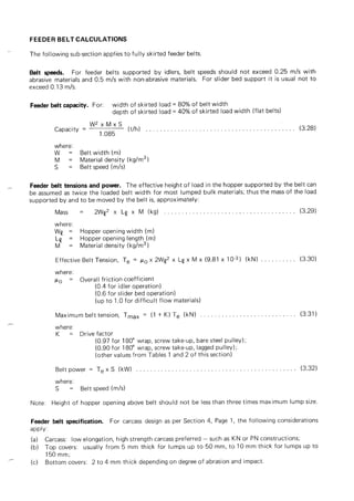
  • 67. TABLE 1A STANDARD CONSTRUCTIONS (other than CoalMaster series) RECOMMENDED MINIMUM PULLEY DIAMETERS For belts operating at over 60% of maximum allowable working tension Number of plies 2 3 4 5 6 PN 150 - 160 PN315 /2 PN500 /3 PN630 /4 PN750 /5 PN900 /6 plain weave Type “A” 315 mm 400 mm 560 mm 710 mm 800 mm Type “B” 250 mm 315 mm 450 mm 560 mm 630 mm Type “C” 200 mm 250 mm 360 mm 450 mm 500 mm PN 200 - 220 PN400 /2 PN630 /3 PN800 /4 PN1000 /5 PN1200 /6 plain weave Type “A” 400 mm 450 mm 630 mm 800 mm 900 mm Type “B” 315 mm 360 mm 500 mm 630 mm 710 mm Type “C” 250 mm 280 mm 400 mm 500 mm 560 mm PN 250 PN500 /2 PN750 /3 PN1000 /4 PN1250 /5 PN1500 /6 plain weave Type “A” 450 mm 500 mm 710 mm 900 mm 1120 mm Type “B” 360 mm 400 mm 560 mm 710 mm 900 mm Type “C” 280 mm 315 mm 450 mm 560 mm 710 mm PN 300 - 315 PN630 /2 PN900 /3 PN1250 /4 PN1500 /5 PN1800 /6 plain weave Type “A” 500 mm 560 mm 800 mm 1120 mm 1400 mm Type “B” 400 mm 450 mm 630 mm 900 mm 1120 mm Type “C” 315 mm 360 mm 500 mm 710 mm 900 mm PN 320 - 350 PN1000 /3 PN1400 /4 PN1600 /5 plain weave Type “A” 630 mm 900 mm 1120 mm Type “B” 500 mm 710 mm 900 mm Type “C” 400 mm 560 mm 710 mm PN 360 - 400 PN800 /2 PN1200 /3 PN1500 /4 PN1800 /5 plain weave Type “A” 560 mm 710 mm 1000 mm 1250 mm Type “B” 450 mm 560 mm 800 mm 1000 mm Type “C” 360 mm 450 mm 630 mm 800 mm PN 315 - 375 PN750 /2 PN1000 /3 PN1250 /4 PN1600 /5 Crow's foot Type “A” 560 mm 710 mm 1000 mm 1250 mm weave Type “B” 450 mm 560 mm 800 mm 1000 mm Type “C” 360 mm 450 mm 630 mm 800 mm PN 360 - 400 PN800 /2 PN1200 /3 PN1500 /4 PN1800 /5 Crow's foot Type “A” 560 mm 800 mm 1000 mm 1250 mm weave Type “B” 450 mm 630 mm 800 mm 1000 mm Type “C” 360 mm 500 mm 630 mm 800 mm PN 450 - 500 PN1500 /3 PN1800 /4 PN2250 /5 Crow's foot Type “A” 900 mm 1250 mm 1600 mm weave Type “B” 710 mm 1000 mm 1250 mm Type “C” 560 mm 800 mm 1000 mm PN 450 PN900 /2 PN1350 /3 Double weave Type “A” 630 mm 1000 mm Type “B” 500 mm 800 mm Type “C” 400 mm 630 mm 6-3