Downloaded 14 times

![Page
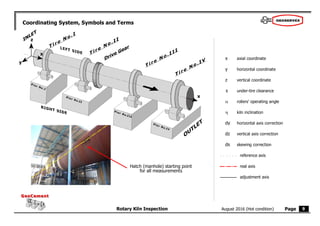
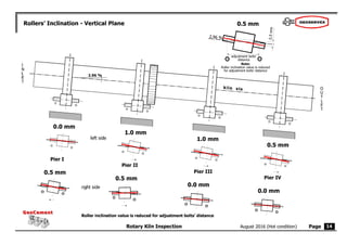
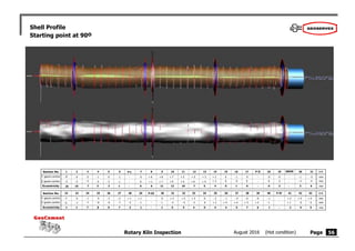
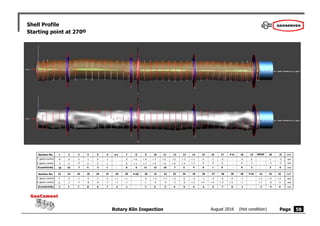
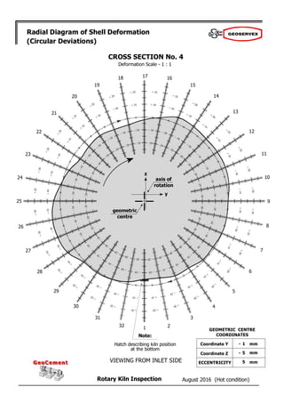
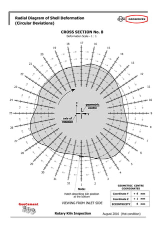
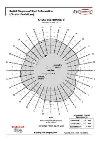
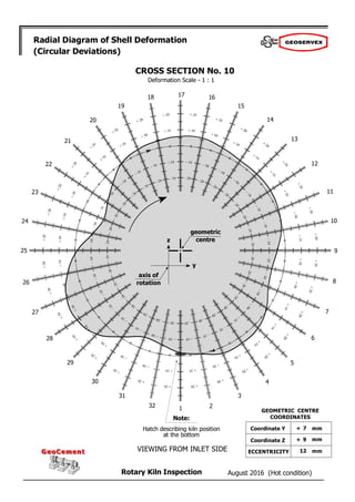
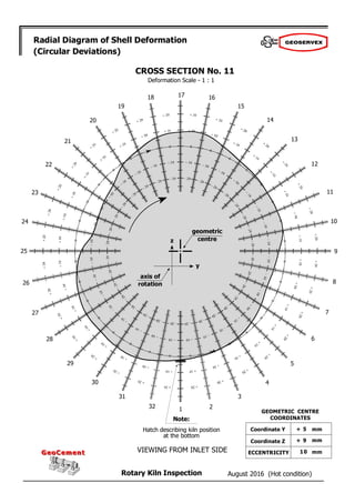
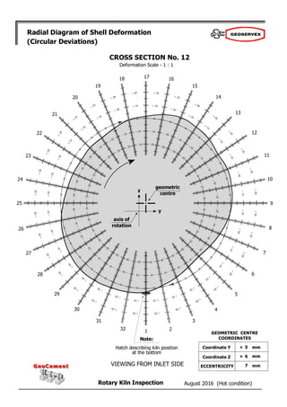
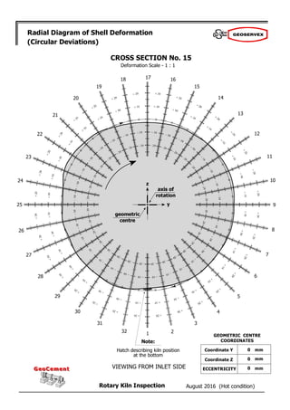
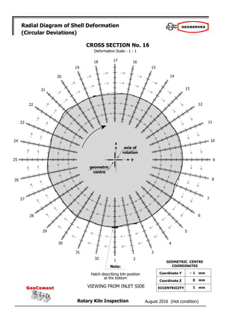
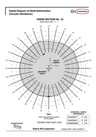
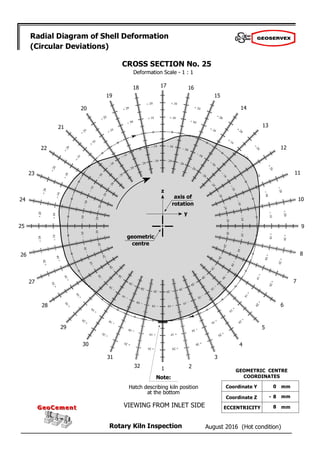
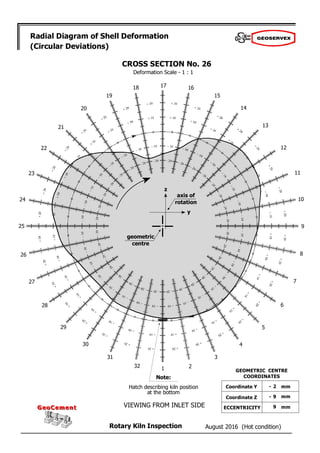
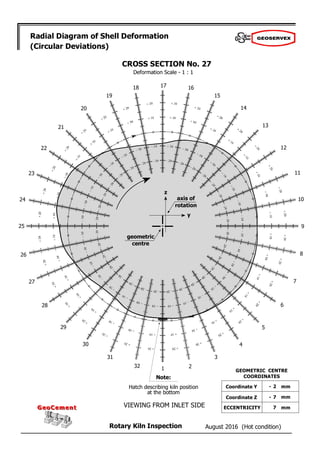
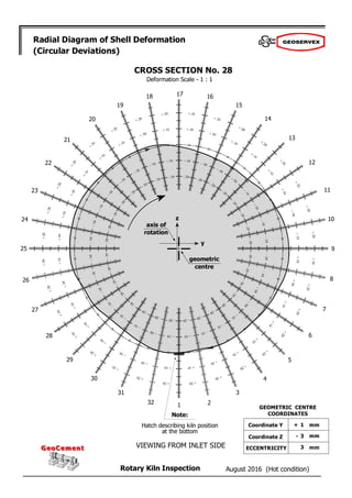
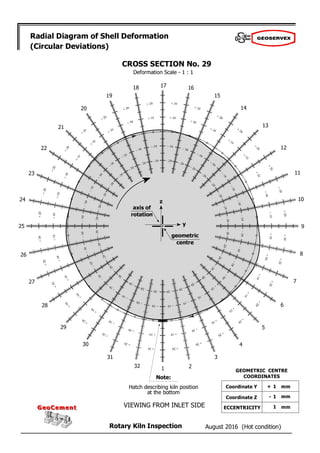
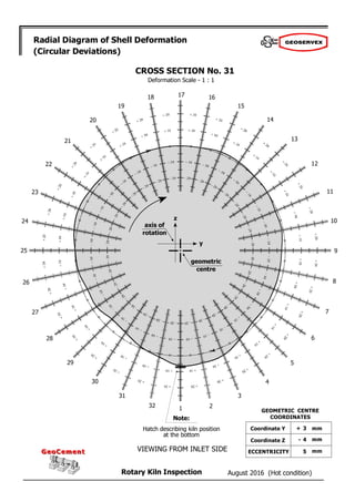
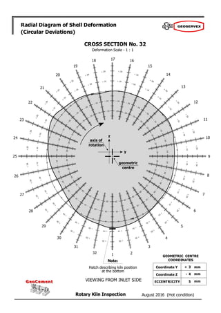
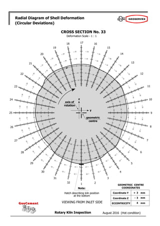
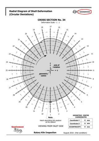
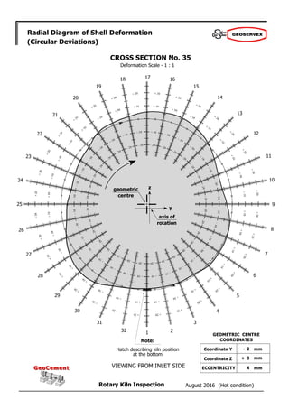
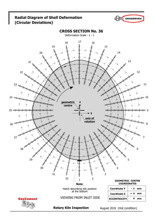
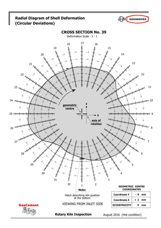
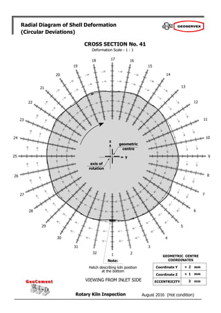
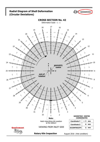
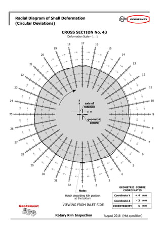
Rotary Kiln Inspection
GeoCement
GeoCement
August 2016 (Hot condition)
y4 =
x4 =
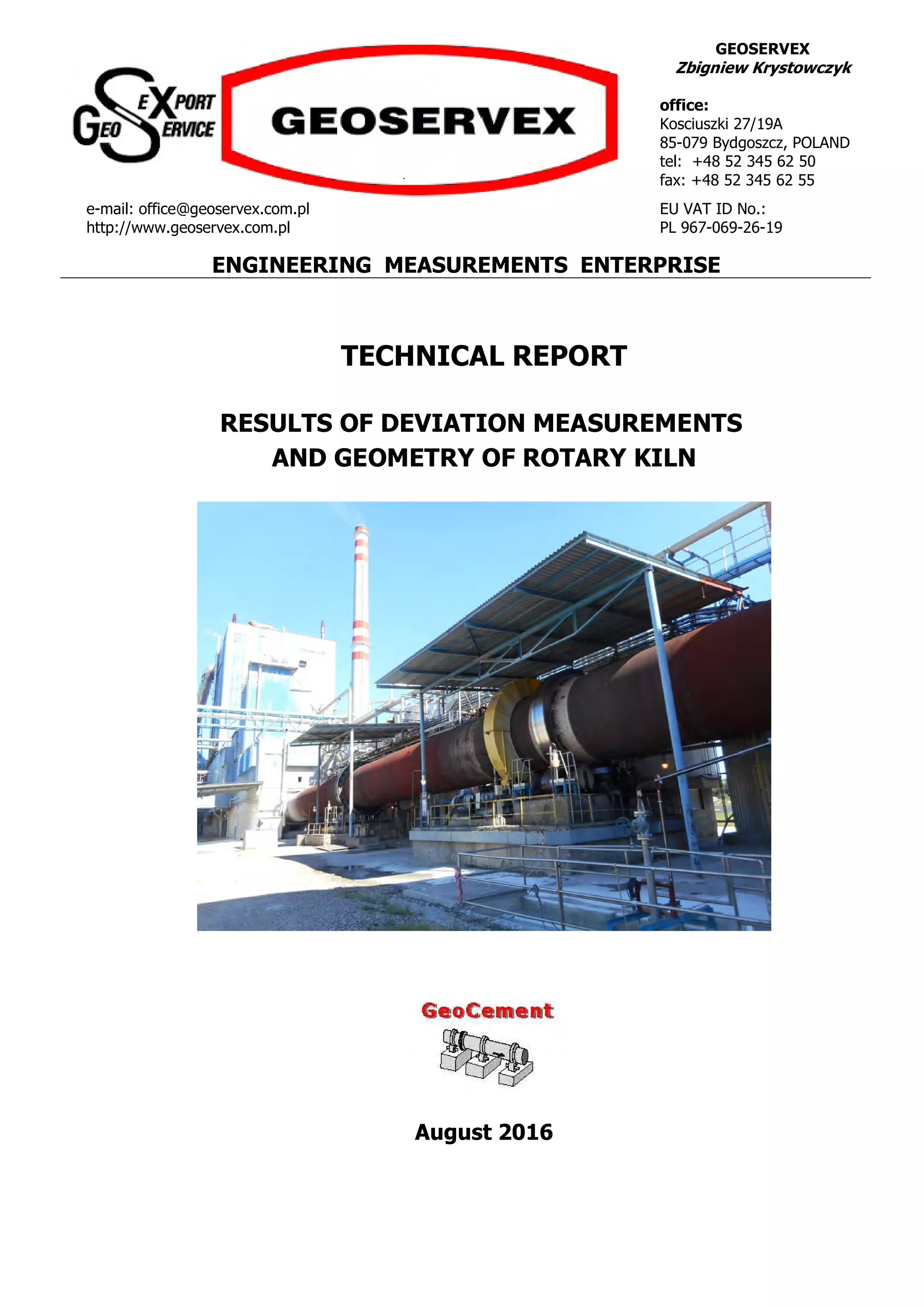
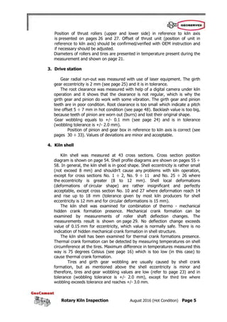
Measurement Data
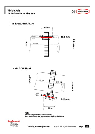
= 2.96 %
2 =
3 =
4 =
,
o
,
o
,
o
,
o
[ ]
[ m ]
x3 =
x2 = 25.57
y3 =
[ mm ]
y2 = - 14.0
[ mm ]
z3 =
z2 =
0.0
z4 =
s4 =
s3 =
[ mm ]
s2 =
Coordinate " z "
Coordinate " x "
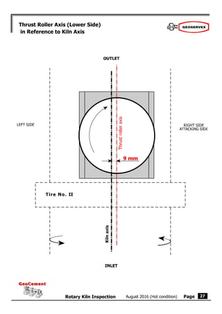
INLET
OUTLET
Under-tire clearance " s "
INLET
OUTLET
INLET
OUTLET
INLET
OUTLET
INLET
OUTLET
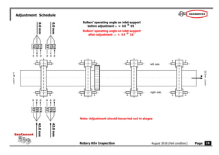
Rollers’ operating angle ""
Coordinate " y "
Kiln inclination
0.0
51.45
77.42
- 6.0
+ 8.0
+ 4.0
5.0
2.5
2.0 60
25
60 20
60
30
10
(average)
1 =
,
x1 = 0.00 y1 = 0.0 z1 =
s1 =
0.0
8.0 05
60
o](https://image.slidesharecdn.com/exemplary-report-rotary-kiln-alignment-210805045923/85/Exemplary-report-rotary-kiln-alignment-10-320.jpg)
![Page
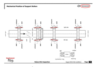
Rotary Kiln Inspection
GeoCement
GeoCement
August 2016 (Hot condition) 16
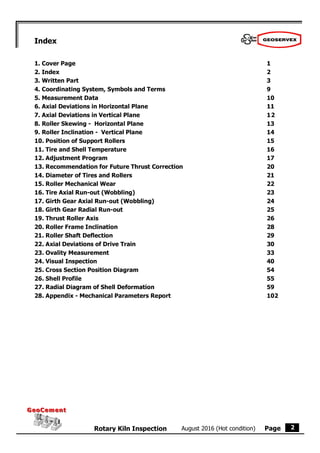
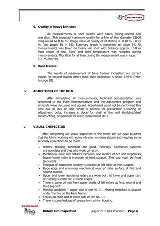
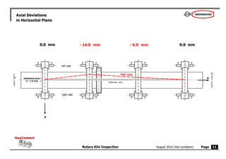
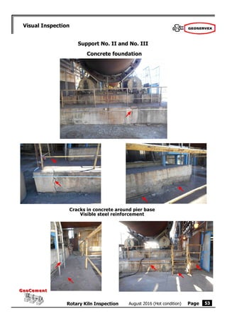
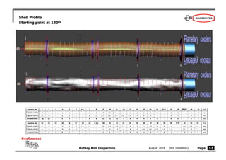
Tires’ and Shell Temperature
Unit: [ C]
Emission factor: 0.95
O
U
T
L
E
T
I
N
L
E
T
100
Date of survey: 24.08.2016
PIER I inlet side outlet side
minimum 136 140
maximum 154 163
difference 18 15
103 156 158 165 155 170 175
PIER II inlet side outlet side
minimum 175 181
maximum 250 204
difference 75 23
PIER III inlet side outlet side
minimum 263 265
maximum 278 287
difference 15 22
PIER IV inlet side outlet side
minimum 279 261
maximum 299 284
difference 20 23](https://image.slidesharecdn.com/exemplary-report-rotary-kiln-alignment-210805045923/85/Exemplary-report-rotary-kiln-alignment-16-320.jpg)


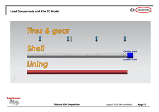
![Rotary Kiln Inspection August 2016 (Hot Condition) Page 2
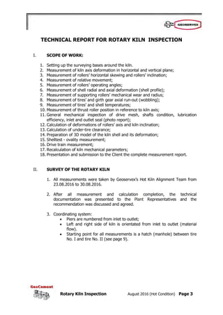
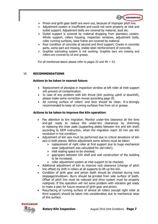
The kiln mechanical parameters were calculated with consideration of actual thickness of
kiln shell, refractory lining, material flow, as well as all dimensions of kiln components and its
current temperature. All results represent the case of straight kiln axis. To illustrate consequences
for the kiln we calculate load capacity utilization of particular parameter referring to its design
limit.
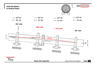
LOAD DISTRIBUTION FOR ROLLERS AND TIRES
BEARINGS TIRES
Specific load Utilization Bending stress Utilization Hertz pressure Utilization
(design limit 4.4 MPa) [ % ] (design limit 60 MPa) [ % ] (design limit 440 MPa) [ % ]
Support No. 1 - - 12.4 21 218.9 50
Support No. 2 - - 13.4 22 244.8 56
Support No. 3 - - 15.1 25 280.5 64
Support No. 4 - - 12.2 20 219.4 50
Results above show that Hertz pressure between rollers and tires as well as bending stress
of tires are within design limits for all supports. Specific load values for bearings are not shown
due to missing (not provided) dimensions of roller bearings.
STIFFNESS MATRIX
Change of reaction in [%] by lowering particular support by 10 mm
Change at
Support
No. 1
Change at
Support
No. 2
Change at
Support
No. 3
Change at
Support
No. 4
Support No. 1 1.5 -4.8 10.1 -5.7
Support No. 2 -8.5 16.9 -27.1 13.0
Support No. 3 12.5 -19.3 24.0 -8.8
Support No. 4 -5.5 7.3 -7.0 1.6
The stiffness matrix illustrates kiln shell characteristics. The results illustrate change of
reaction of all supports when particular support is lowered by 10 mm. Considering maximum
reaction value of 27.1 % this kiln is classified as medium flexible. It means the kiln is not very
sensitive for change of kiln axis position and reactions at supports do not change drastically.
Anyway, it is still recommended to pay attention to the kiln alignment and under-tire clearance
changes to avoid overload in the future.](https://image.slidesharecdn.com/exemplary-report-rotary-kiln-alignment-210805045923/85/Exemplary-report-rotary-kiln-alignment-103-320.jpg)
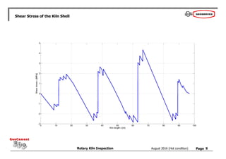
![Rotary Kiln Inspection August 2016 (Hot Condition) Page 3
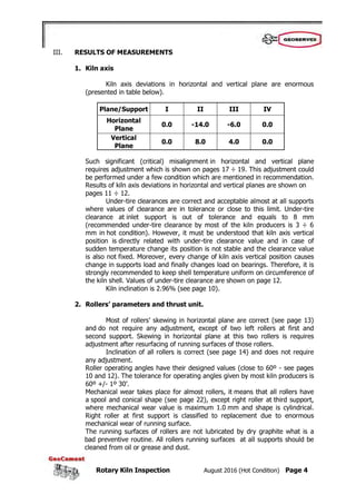
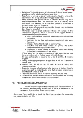
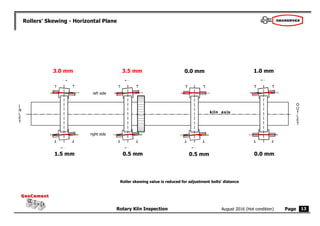
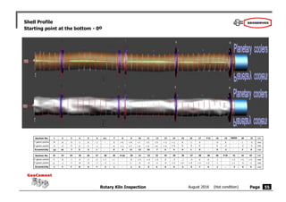
Kiln shell bending stress reaches 17 MPa and it is within designed limits (25 MPa). It looks
there is some spare limit for shell bending stress. However, it has to be considered that the
results above represent straight kiln in static condition and without any shell deformation or crank
formation. The kiln (as designed) is not overloaded at any support and theoretically shall not be a
subject to cracks due to bending stress.
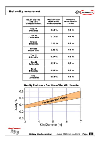
TIRE MIGRATION, SHELL RELATIVE OVALITY, NIES OVALITY FOR TIRES
SHELL TIRES
Rel. ovality Utilization Migration Nies ovality Utilization
(design limit 0.30%) [ % ] (recommended: 10 mm/rev) (design limit 0.20%) [ % ]
Support No. 1 0.285 95 25 0.032 16
Support No. 2 0.241 80 19 0.040 20
Support No. 3 0.145 48 9 0.052 26
Support No. 4 0.096 32 6 0.032 16
Tire migration is in tolerance (10 – 20mm) for supports No. 2 and No. 3. For supports
No. 1 and No. 2 tire migration slightly exceeds tolerance. Nies ovality is within tolerance for all
tires. Relative ovality for support No. 1 is almost on design limit (consequence of tire migration).
In general, the kiln mechanical parameters are within design limits. The kiln is definitely
not overloaded in terms of support loads, tire stress and Hertz pressure between tires and rollers.
Also the kiln shell bending stress is within designed limit. However, it should be considered that
all the design limits correspond to static condition and in fact all parameters are frequently much
higher due to cyclical load change during kiln operation (crank effect). It is recommended to
monitor the bearings condition and temperature frequently.
Technical drawings of calculation results are attached at the end of this report.](https://image.slidesharecdn.com/exemplary-report-rotary-kiln-alignment-210805045923/85/Exemplary-report-rotary-kiln-alignment-104-320.jpg)
![Page
Rotary Kiln Inspection
GeoCement
GeoCement
August 2016 (Hot condition)
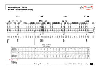
Weight distribution [t/m]
6](https://image.slidesharecdn.com/exemplary-report-rotary-kiln-alignment-210805045923/85/Exemplary-report-rotary-kiln-alignment-107-320.jpg)
![Page
Rotary Kiln Inspection
GeoCement
GeoCement
August 2016 (Hot condition)
Longitudinal Bending Stress of the Kiln Shell [MPa]
7](https://image.slidesharecdn.com/exemplary-report-rotary-kiln-alignment-210805045923/85/Exemplary-report-rotary-kiln-alignment-108-320.jpg)
![Page
Rotary Kiln Inspection
GeoCement
GeoCement
August 2016 (Hot condition)
Vertical Displacement of the Kiln Shell [mm]
8](https://image.slidesharecdn.com/exemplary-report-rotary-kiln-alignment-210805045923/85/Exemplary-report-rotary-kiln-alignment-109-320.jpg)
![Page
Rotary Kiln Inspection
GeoCement
GeoCement
August 2016 (Hot condition)
Von Mises Stress of the Kiln Shell [MPa]
10](https://image.slidesharecdn.com/exemplary-report-rotary-kiln-alignment-210805045923/85/Exemplary-report-rotary-kiln-alignment-111-320.jpg)
![Page
Rotary Kiln Inspection
GeoCement
GeoCement
August 2016 (Hot condition)
Bending Stress of Tires [MPa]
11
Support 3
Support 4](https://image.slidesharecdn.com/exemplary-report-rotary-kiln-alignment-210805045923/85/Exemplary-report-rotary-kiln-alignment-112-320.jpg)
![Page
Rotary Kiln Inspection
GeoCement
GeoCement
August 2016 (Hot condition)
Bending Stress of Tires [MPa]
12
Support 2 Support 1](https://image.slidesharecdn.com/exemplary-report-rotary-kiln-alignment-210805045923/85/Exemplary-report-rotary-kiln-alignment-113-320.jpg)

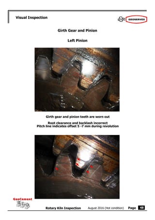
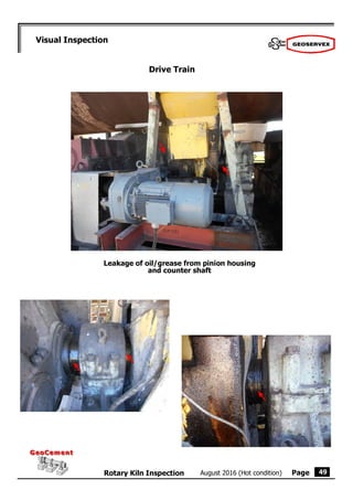
This technical report summarizes the results of deviation measurements and geometry inspection of a rotary kiln. Key findings include: - Significant misalignments were found in the kiln axis in both the horizontal and vertical planes, requiring adjustment. - Most rollers were found to be in acceptable condition, though some had mechanical wear or required skewing adjustments. - The kiln shell was in generally good condition with minor eccentricities, though a few sections showed larger deformations. - The drive station showed gear and pinion wear as well as vibrations, indicating the need for inspection and possible component replacement during the next shutdown. - Recommendations included adjustments to the kiln axis and drive


