Download as PDF, PPTX

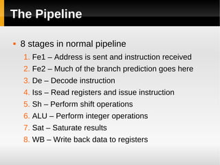

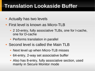
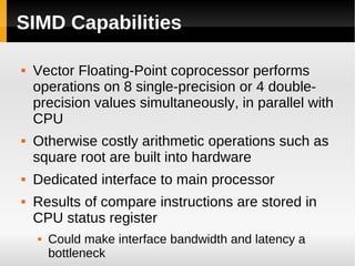

The ARM11 architecture uses a RISC design with 32-bit ARM and 16-bit Thumb instruction sets. It has a pipeline with stages for instruction fetch, decode, register access, shift, ALU operations, and write back. The ARM11 uses branch prediction including a branch target address cache and static prediction rules. It has a memory hierarchy including separate instruction and data caches, a TLB for virtual to physical address translation, and an optional L2 cache. Vector floating-point operations can be performed in parallel by a coprocessor.