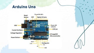
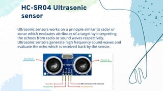
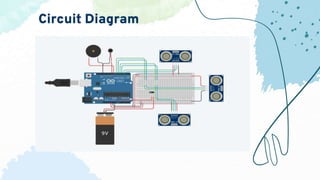
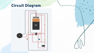
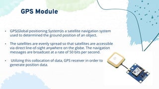
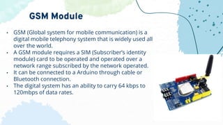
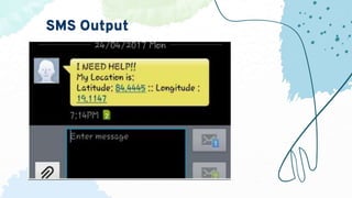
Arduino
Blind Aid
Blind Navigation by using Arduino is about the
project that helps blind community to get better
access to the environment. The design is
incorporated with Ultrasonic sensor for
Obstacle detection and a dark sensor for
detecting darkness and a buzzer to alert the
blind. Ultrasonic sensors are used to calculate
the distance of the obstacle around the blind
person.
Introduction
This model includes two
different detectors.
-Obstacle Detector
-Dark Detector
Arduino Uno
9 V battery
3 HC-SR04 Ultrasonic sensors
Bread board
Buzzer
Vibration Motor
Slide Switch
Jumper wires
Components used in
Obstacle Detector
• The Arduino UNO is a standard board of Arduino. Here UNO means
'one' in Italian.
• It was named as UNO to label the first release of Arduino Software. It
was also the first USB board released by Arduino.
• It is considered as the powerful board used in various projects.
Arduino.cc developed the Arduino UNO board.
• Arduino UNO is based on an ATmega328P microcontroller. It is easy
to use compared to other boards, such as the Arduino Mega board,
etc.
• The board consists of digital and analog Input/Output pins (I/O),
shields, and other circuits.
• The Arduino UNO includes 6 analog pin inputs, 14 digital pins,
a USB connector, a power jack, and an ICSP (In-Circuit Serial
Programming) header.
• It is programmed based on IDE, which stands for Integrated
Development Environment. It can run on both online and offline
platforms.
Arduino Uno
Arduino Uno
Ultrasonic sensors works on a principle similar to radar or
sonar which evaluates attributes of a target by interpreting
the echoes from radio or sound waves respectively.
Ultrasonic sensors generate high frequency sound waves and
evaluate the echo which is received back by the sensor.
HC-SR04 Ultrasonic
sensor
• The Ultrasonic Sensor is a Transceiver Module (Transmitter
+ Receiver).
• It transmits High Frequency Ultrasonic Waves of frequency
greater than 20 KHz.
• Intercepts the waves reflected by an obstacle.
• Electrical Signals ↔ Ultrasonic Signals ↔ Electrical Signals
Working Principle
Working Principle
Working Principle
Pin Configuration
• It provides 2 - 400 cm non-contact measurement
function.
• Operating Voltage : 5V
• Working Frequency : 40 KHz
• Trigger Input Signal : 10μs TTL pulse
Specifications
Piezoelectric Buzzer
• A buzzer or beeper is a signaling device, commonly consists
of a number of switches or sensors connected to a control
unit that determines if and which button was pushed or a
preset time has lapsed, and usually illuminates a light on the
appropriate button or control panel, and sounds a warning in
the form of a continuous or intermittent buzzing or beeping
sound.
Vibration Motor
• A vibrating motor is essentially a motor that is improperly balanced. In
other words, there is an off-centered weight attached to the motor's
rotational shaft that causes the motor to wobble. The amount of
wobble can be changed by the amount of weight attached, the
weight's distance from the shaft, and the speed at which the motor
spins.
• Vibrating motors can be found inside cell phones, pagers, gaming
controllers.
Flow chart of the detector
Circuit Diagram
Code
9 V battery
Timer 555 IC
Piezoelectric Buzzer
LDR sensor
3 5K ohms resistor
2 Capacitors
Jumper wires
Components used
in Dark Detector
The 555 Timer IC got its name from the three 5KΩ resistors
that are used in its voltage divider network. This IC is useful
for generating accurate time delays and oscillations. This 555
Timer IC can be operated with a DC supply of +5V to +18V. It
is mainly useful for generating non-sinusoidal wave forms
like square, ramp, pulse & etc
Timer 555 IC
Functional Diagram
Of Timer 555 IC
Wave generation
LDR is a photoresistor.Its resistance depends on intensity of
electromagnetic radiation falling on it.When sufficient
amount of light falls on it ,its resistance will be low otherwise
it will be high.
LDR
Circuit Diagram
• Ultrasonic sensor is used for obstacle avoidance. The vibrator
vibrates when an obstacle is encountered which helps in
alerting the blind person and allows enough time to change
their path.
• Dark sensor is useful at late evenings and night. It alerts the
blind person that the surrounding area is getting darker and
alerts him with a buzzer.
Usage of different sensors
The project proposed the design and architecture of a new
concept of Smart Electronic Guiding Stick for blind people.
The advantage of the system lies in the fact that it can prove
to be very low cost solution to millions of blind person
worldwide. The proposed combination of various working
units makes a real-time system that monitors position of the
user and provides dual feedback making navigation more
safe and secure. It can be further improved to have more
decision taking capabilities by employing varied types of
sensors and thus could be used for different applications. It
aims to solve the problems faced by the blind people in their
daily life. The system also takes measures to ensure their
safety.
Conclusion
It can be further enhanced by using VLSI technology to
design the PCB unit. This makes the system further
more compact. Also, use of active RFID tags will
transmit the location information automatically to the
PCB unit, when the intelligent stick is in its range. The
RFID sensor doesn’t have to read it explicitly. The
global position of the user is obtained using the global
positioning system (GPS), and their current position
and guidance to their destination will be given to the
user by voice.
Future Scope
• GPS(Global positioning System)is a satellite navigation system
used to determined the ground position of an object.
• The satellites are evenly spread so that satellites are accessible
via direct line-of-sight anywhere on the globe. The navigation
messages are broadcast at a rate of 50 bits per second.
• Utilizing this collocation of data, GPS receiver in order to
generate position data.
GPS Module
• GSM (Global system for mobile communication) is a
digital mobile telephony system that is widely used all
over the world.
• A GSM module requires a SIM (Subscriber’s identity
module) card to be operated and operated over a
network range subscribed by the network operated.
• It can be connected to a Arduino through cable or
Bluetooth connection.
• The digital system has an ability to carry 64 kbps to
120mbps of data rates.
GSM Module
SMS Output
Nischinth
Yogiraj
Mani Teja
Mukthesh
01
02
03
04
Team Mates
05 Rohith
Thank
You

Arduino Blind Aid

  • 1.
  • 2.
    Blind Navigation byusing Arduino is about the project that helps blind community to get better access to the environment. The design is incorporated with Ultrasonic sensor for Obstacle detection and a dark sensor for detecting darkness and a buzzer to alert the blind. Ultrasonic sensors are used to calculate the distance of the obstacle around the blind person. Introduction
  • 3.
    This model includestwo different detectors. -Obstacle Detector -Dark Detector
  • 4.
    Arduino Uno 9 Vbattery 3 HC-SR04 Ultrasonic sensors Bread board Buzzer Vibration Motor Slide Switch Jumper wires Components used in Obstacle Detector
  • 5.
    • The ArduinoUNO is a standard board of Arduino. Here UNO means 'one' in Italian. • It was named as UNO to label the first release of Arduino Software. It was also the first USB board released by Arduino. • It is considered as the powerful board used in various projects. Arduino.cc developed the Arduino UNO board. • Arduino UNO is based on an ATmega328P microcontroller. It is easy to use compared to other boards, such as the Arduino Mega board, etc. • The board consists of digital and analog Input/Output pins (I/O), shields, and other circuits. • The Arduino UNO includes 6 analog pin inputs, 14 digital pins, a USB connector, a power jack, and an ICSP (In-Circuit Serial Programming) header. • It is programmed based on IDE, which stands for Integrated Development Environment. It can run on both online and offline platforms. Arduino Uno
  • 6.
  • 7.
    Ultrasonic sensors workson a principle similar to radar or sonar which evaluates attributes of a target by interpreting the echoes from radio or sound waves respectively. Ultrasonic sensors generate high frequency sound waves and evaluate the echo which is received back by the sensor. HC-SR04 Ultrasonic sensor
  • 8.
    • The UltrasonicSensor is a Transceiver Module (Transmitter + Receiver). • It transmits High Frequency Ultrasonic Waves of frequency greater than 20 KHz. • Intercepts the waves reflected by an obstacle. • Electrical Signals ↔ Ultrasonic Signals ↔ Electrical Signals
  • 9.
  • 10.
  • 11.
  • 12.
  • 13.
    • It provides2 - 400 cm non-contact measurement function. • Operating Voltage : 5V • Working Frequency : 40 KHz • Trigger Input Signal : 10μs TTL pulse Specifications
  • 14.
    Piezoelectric Buzzer • Abuzzer or beeper is a signaling device, commonly consists of a number of switches or sensors connected to a control unit that determines if and which button was pushed or a preset time has lapsed, and usually illuminates a light on the appropriate button or control panel, and sounds a warning in the form of a continuous or intermittent buzzing or beeping sound.
  • 15.
    Vibration Motor • Avibrating motor is essentially a motor that is improperly balanced. In other words, there is an off-centered weight attached to the motor's rotational shaft that causes the motor to wobble. The amount of wobble can be changed by the amount of weight attached, the weight's distance from the shaft, and the speed at which the motor spins. • Vibrating motors can be found inside cell phones, pagers, gaming controllers.
  • 16.
    Flow chart ofthe detector
  • 17.
  • 18.
  • 19.
    9 V battery Timer555 IC Piezoelectric Buzzer LDR sensor 3 5K ohms resistor 2 Capacitors Jumper wires Components used in Dark Detector
  • 20.
    The 555 TimerIC got its name from the three 5KΩ resistors that are used in its voltage divider network. This IC is useful for generating accurate time delays and oscillations. This 555 Timer IC can be operated with a DC supply of +5V to +18V. It is mainly useful for generating non-sinusoidal wave forms like square, ramp, pulse & etc Timer 555 IC
  • 21.
  • 22.
  • 23.
    LDR is aphotoresistor.Its resistance depends on intensity of electromagnetic radiation falling on it.When sufficient amount of light falls on it ,its resistance will be low otherwise it will be high. LDR
  • 24.
  • 25.
    • Ultrasonic sensoris used for obstacle avoidance. The vibrator vibrates when an obstacle is encountered which helps in alerting the blind person and allows enough time to change their path. • Dark sensor is useful at late evenings and night. It alerts the blind person that the surrounding area is getting darker and alerts him with a buzzer. Usage of different sensors
  • 26.
    The project proposedthe design and architecture of a new concept of Smart Electronic Guiding Stick for blind people. The advantage of the system lies in the fact that it can prove to be very low cost solution to millions of blind person worldwide. The proposed combination of various working units makes a real-time system that monitors position of the user and provides dual feedback making navigation more safe and secure. It can be further improved to have more decision taking capabilities by employing varied types of sensors and thus could be used for different applications. It aims to solve the problems faced by the blind people in their daily life. The system also takes measures to ensure their safety. Conclusion
  • 27.
    It can befurther enhanced by using VLSI technology to design the PCB unit. This makes the system further more compact. Also, use of active RFID tags will transmit the location information automatically to the PCB unit, when the intelligent stick is in its range. The RFID sensor doesn’t have to read it explicitly. The global position of the user is obtained using the global positioning system (GPS), and their current position and guidance to their destination will be given to the user by voice. Future Scope
  • 28.
    • GPS(Global positioningSystem)is a satellite navigation system used to determined the ground position of an object. • The satellites are evenly spread so that satellites are accessible via direct line-of-sight anywhere on the globe. The navigation messages are broadcast at a rate of 50 bits per second. • Utilizing this collocation of data, GPS receiver in order to generate position data. GPS Module
  • 29.
    • GSM (Globalsystem for mobile communication) is a digital mobile telephony system that is widely used all over the world. • A GSM module requires a SIM (Subscriber’s identity module) card to be operated and operated over a network range subscribed by the network operated. • It can be connected to a Arduino through cable or Bluetooth connection. • The digital system has an ability to carry 64 kbps to 120mbps of data rates. GSM Module
  • 30.
  • 31.
  • 32.