CONTENTS
• INTRODUCTION
• BASICLOGIC
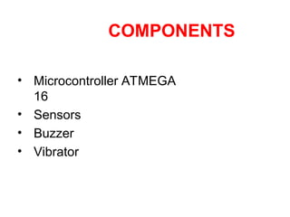
• COMPONENTS
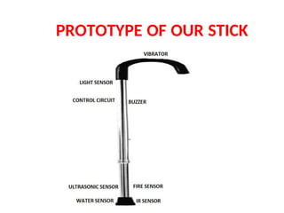
• PROTOTYPE OF OUR STICK
• USAGE OF DIFFERENT SENSORS
• ATMEGA 16
• ULTRASONIC SENSOR
• IR SENSOR
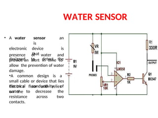
• WATER SENSOR
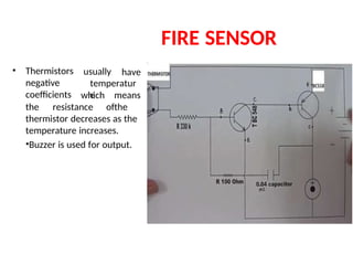
• FIRE SENSOR
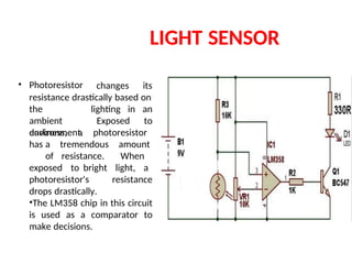
• LIGHT SENSOR
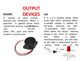
• OUTPUT DEVICES
• SOFTWARE USED
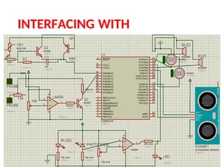
• INTERFACING WITH
CONTROLLER
• CONCLUSION
• FUTURE SCOPE
• REFERENCES
3.
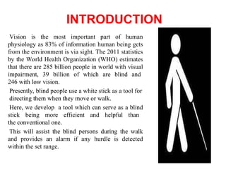
INTRODUCTION
Vision is themost important part of human
physiology as 83% of information human being gets
from the environment is via sight. The 2011 statistics
by the World Health Organization (WHO) estimates
that there are 285 billion people in world with visual
impairment, 39 billion of which are blind and
246 with low vision.
Presently, blind people use a white stick as a tool for
directing them when they move or walk.
Here, we develop a tool which can serve as a blind
stick being more efficient and helpful than
the conventional one.
This will assist the blind persons during the walk
and provides an alarm if any hurdle is detected
within the set range.
4.
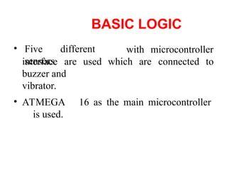
BASIC LOGIC
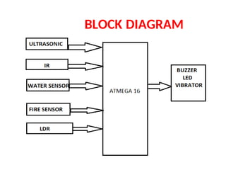
• Fivedifferent
sensors
with microcontroller
interface are used
buzzer and
vibrator.
which are connected to
• ATMEGA 16 as the main microcontroller
is used.
USAGE OF DIFFERENT
SENSORS
•Ultrasonic sensor is used for obstacle avoidance. The vibrator
vibrates when an obstacle is encountered which helps in alerting the
blind person and allows enough time to change their path.
• IR sensor is used for pit and staircase detection.
• Water sensor is used to detect the presence of water and provide an
alert
in time for path change so as to avoid slipping.
• Fire sensor is used for avoiding fire.
• Light sensor is useful at night. It alerts the people in the surrounding area
that a blind person is walking and to allow space so that the blind person
can walk easily.
9.
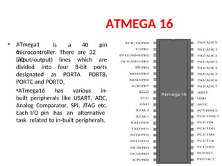
ATMEGA 16
• ATmega1
6
isa 40 pin
microcontroller. There are 32
I/O
(input/output) lines
four
which
8-bit
are
ports
divided into
designated as PORTA
,
PORTB,
PORTC and PORTD.
•ATmega16 has various in-
built peripherals like USART, ADC,
Analog Comparator, SPI, JTAG etc.
Each I/O pin has an alternative
task related to in-built peripherals.
10.
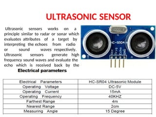
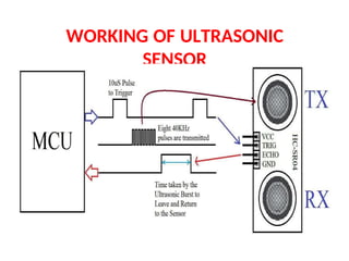
ULTRASONIC SENSOR
Ultrasonic sensorsworks on a
principle similar to radar or sonar which
evaluates attributes of a target by
interpreting the echoes from radio
or sound waves respectively.
Ultrasonic sensors generate high
frequency sound waves and evaluate the
echo which is received back by the
sensor.
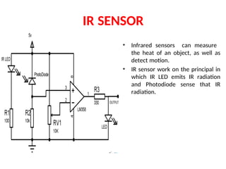
IR SENSOR
• Infraredsensors can measure
the heat of an object, as well as
detect motion.
• IR sensor work on the principal in
which IR LED emits IR radiation
and Photodiode sense that IR
radiation.
WATER SENSOR
presence ofwater and
provide an alert in time to
allow the prevention of water
damage.
•A common design is a
small cable or device that lies
flat on a floor and relies
on the
• A water sensor
is
an
electronic device
that
is
designed to detect the
electrical conductivity of
water to decrease the
resistance across two
contacts.
15.
LIGHT SENSOR
• Photoresistorchanges its
resistance drastically based on
the
ambient
environment.
lighting in an
to
Exposed
darkness, a photoresistor
has a tremendous amount
of resistance. When
exposed to bright light, a
photoresistor's resistance
drops drastically.
•The LM358 chip in this circuit
is used as a comparator to
make decisions.
16.
OUTPUT
DEVICES
BUZZER
It consists ofpiezo crystals
between two conductors. When a
potential is applied across these
crystals they push on one conductor
and
other. This, push and
results in a sound wave.
pull on
the pull
action,
LED
It is a p–n junction diode, which
emits light when activated. When
a suitable voltage is applied to
the leads, electrons are able
to recombine with electron
holes within the device, releasing
energy in the form of photons.
This effect is called
electroluminescence, and the color
of the light is determined by the
energy band gap of the
semiconductor.
17.
OUTPUT DEVICES
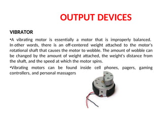
VIBRATOR
•A vibratingmotor is essentially a motor that is improperly balanced.
In other words, there is an off-centered weight attached to the motor's
rotational shaft that causes the motor to wobble. The amount of wobble can
be changed by the amount of weight attached, the weight's distance from
the shaft, and the speed at which the motor spins.
•Vibrating motors can be found inside cell phones, pagers, gaming
controllers, and personal massagers
CONCLUSION
• The projectproposed the design and architecture of a new concept
of Smart Electronic Guiding Stick for blind people. The advantage of
the system lies in the fact that it can prove to be very low cost
solution to millions of blind person worldwide. The proposed
combination of various working units makes a real-time system that
monitors position of the user and provides dual feedback making
navigation more safe and secure.
• It can be further improved to have more decision taking capabilities
by employing varied types of sensors and thus could be used for
different applications. It aims to solve the problems faced by the blind
people in their daily life. The system also takes measures to ensure their
safety.
21.
FUTURE SCOPE
• Itcan be further enhanced by using VLSI technology to design the
PCB unit. This makes the system further more compact. Also, use of active
RFID tags will transmit the location information automatically to the PCB
unit, when the intelligent stick is in its range. The RFID sensor doesn’t have
to read it explicitly.
• The global position of the user is obtained using the global
positioning system (GPS), and their current position and guidance to their
destination will be given to the user by voice.
REFRENCES
• Abhishek Choubey,Dattatray Patil, “RFID Based Cognition Device for Assistance
to Blind and Visually Challenged Persons for Indoor Use”, International Journal
of Engineering and Innovative Technology (IJEIT) Volume 1, Issue 6, June 2012.
• João José, Miguel Farrajota, João M.F. Rodrigues, J.M. Hans du Buf, “The Smart Vision
Local Navigation Aid for Blind and Visually Impaired Persons‖ International Journal of
Digital Content Technology and its Applications” Vol.5 No.5, May 2011.
• Calder, David J, “Curtin .An obstacle signaling system for the blind ,Digital Ecosystems
and Technologies Conference (DEST)” 5th IEEE International Conference ,30 June 2011
• Bouvrie J . V ., “ Visual Object Concept Discovery: Observation in Congeniality Blind
Children , and a Computational Approach”, Elsevier Science, USA, 2007
• . Mazo M. and Rodriguez F. J., “ Wheelchair for Physical Disable People With
Voice
,Ultrasonic and Infrared Control”, Autonomous Robots, Vol. 2, pp. 203-224,