This document presents the development of an Arduino-based scientific calculator that performs basic and some scientific functions, utilizing a real-time user input through a keypad and an LCD for outputs. The project emphasizes efficient programming in C to handle various operations, and includes a simulated design and experimental testing using Proteus software. The results show accurate calculations and the design is aimed at enhancing the understanding of mathematical operations through a user-friendly interface.


![International Journal of Trend in Scientific Research and Development (IJTSRD) @ www.ijtsrd.com eISSN: 2456-6470
@ IJTSRD | Unique Paper ID – IJTSRD26395 | Volume – 3 | Issue – 5 | July - August 2019 Page 518
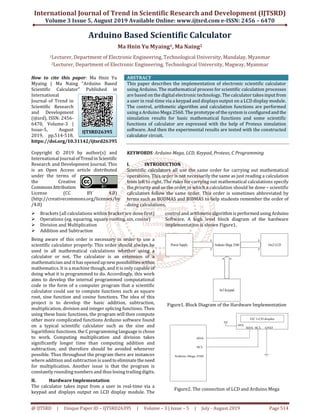
Figure9. Photo of the Constructed Calculator Circuit
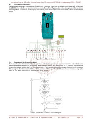
Figure10. Experimental Result of “Addition” Function
VI. Discussions
This scientific calculator contains the basic arithmetic
operations and some scientific functions that can be used
easily. Scientific calculator all use the same order for
carrying out mathematical operations. This order is not
necessarily the same as just reading a calculationfromleftto
right. There are two types of scientific calculator, the most
recent type being algebraic scientific calculators. Algebraic
scientific calculators allowtheuserstotypeincalculationsin
the order in which they have been written down. Older
scientific calculators need users to press the mathematical
operation key after they have entered the number. For
example to find the Sine of ninety, in algebraic scientific
calculator it must be pressed [SINE, 90, =]. In non algebraic
scientific calculator, it is need to press [90, SINE, =]. In this
study, non algebraic type scientific calculator is developed.
This research aims to develop the Arduino based scientific
calculator that can use to compute the basic mathematical
functions and some scientific functions such as square,
square root, sine function and cosine function. The systemis
demonstrated with a small model whichiscomposedofLCD,
a keypad and the Arduino Mega.
VII. Conclusion
This paper aims to develop the Arduino based scientific
calculator that can use to compute the basic mathematical
functions and some scientific functions such as square,
square root, sine function and cosine function. The systemis
demonstrated with a small model whichiscomposedofLCD,
a keypad and the Arduino Mega. The code is as easily
programmed as possible and that the program is to be as
efficient as possible at computing the functions. In theory
and through all practical testing, it is found that the
calculations that are output are accurate to the two
significant Figure requirement. It is extremely unlikely for
any realistic design of a commercial calculator to use a
Arduino Mega Board. The role and operation of Arduino in
scientific calculator are explained. This focus on successful
algorithm implementation that could properlyhandleallthe
cases of calculation functions.
VIII. REFERENCES
[1] [18Ano1] Anonymous, Arduino–ArduinoBoard
Mega2560, 2018.http://www.ard-uino.cc/en/Main
/ArduinoBoard Mega2560?setlang
[2] [18Ano2] Anonymous, Arduino-PinMapping 2560,
2018.http://www.arduino.cc/en/Hacking/PinMapping
2560
[3] [17Tar] Tarun Agarwal, Different Types of Arduino
Boards, 2017. http://www. elprocus. com/different-
types-of-arduino boards/
[4] [13Wik] Wikipedia: Push-button, 2013.
https://en.wikipedia.org/wiki/Push-button
[5] [12Ano] Anonymous, Serial I2C 1602 16x2 Character
LCD Module, 2012.www. geeetech.com/
Serial_I2C_1602_16x2_Character_LCD_Module
[6] [08Ano] Anonymous, LCD - Liquid Crystal Display
tutorial, 2008.
http://www.microcontrollerboard.com/lcd.html
[7] [06Ano] Anonymous, Liquid Crystal Display (LCD),
2006.http://www.chipdoc.com/datasheets/liquidcryst
aldisplay.html](https://image.slidesharecdn.com/93arduinobasedscientificcalculator-190907081156/85/Arduino-Based-Scientific-Calculator-5-320.jpg)