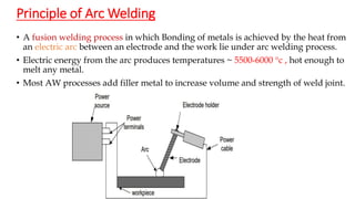
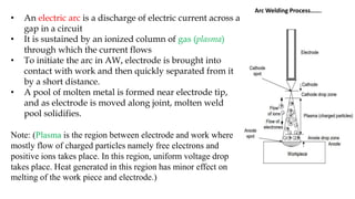
SlideShare a Scribd company logo
Arc Welding process
By: Ajay Kumar
Email Id: ajay.kumar@utu.ac.in
Asst. Prof. Mech/Auto Department
CGPIT, UTU Bardoli
WELDING PROCESSES
 Best fastening(joining) method for metals.
 Welding is a process of joining two metal work-piece by heating them with or
without the application of pressure and filler material.
 Welding is used for making permanent joints.
 It is used in the manufacture of automobile bodies, aircraft frames, railway
wagons, machine frames etc.
 Filler material is used in welding for making welding strong and the composition
of filler material is same as the composition of parent metal (Work-piece)
Weldability:
Weldability of metal refers to the ability of material to be get welded.
Ex: The wood can not be welded but mild steel can be welded.
Classification of welding according to Heat source and
arrangement
Principle of Arc Welding
• A fusion welding process in which Bonding of metals is achieved by the heat from
an electric arc between an electrode and the work lie under arc welding process.
• Electric energy from the arc produces temperatures ~ 5500-6000 c , hot enough to
melt any metal.
• Most AW processes add filler metal to increase volume and strength of weld joint.
Arc Welding Process…….
• An electric arc is a discharge of electric current across a
gap in a circuit
• It is sustained by an ionized column of gas (plasma)
through which the current flows
• To initiate the arc in AW, electrode is brought into
contact with work and then quickly separated from it
by a short distance.
• A pool of molten metal is formed near electrode tip,
and as electrode is moved along joint, molten weld
pool solidifies.
Note: (Plasma is the region between electrode and work where
mostly flow of charged particles namely free electrons and
positive ions takes place. In this region, uniform voltage drop
takes place. Heat generated in this region has minor effect on
melting of the work piece and electrode.)
Arc Welding Process
Setup : Arc welding setup mainly involved:
 Power source
 Electrode (consumable or non-
consumable)
 Filler Rod
 Shielding arrangement (inert or non-
reactive gases)
Power source:
1. Alternating current (ac) machine
a) Transformer b) Motor or engine driven alternator
2. Direct current (dc) machine
a) Transformer with dc rectifier b) Motor or engine driven generator
1. Alternating current: Alternating current (AC) is an electric current which periodically reverses direction, in contrast
to direct current (DC) which flows only in one direction. Due to this reason polarity has no effect during welding using
ac power source but uniform heat is obtained on anode(+) and cathode(-).
2. DC power source : Direct current (DC) is the unidirectional flow of electric charge. A battery is a good example of a
DC power supply. Direct current may be obtained from an alternating current supply by using rectifier.
As in dc power source, polarity don’t have alternating nature thus during dc arc welding, workpiece and electrode
holder can be connected either positive or negative terminal.
On this basis dc electric source polarity can be classified in two ways,
a) Straight polarity and, b) Reverse polarity
Polarity in Arc Welding
Workpiece positive and electrode negative or DCEN Workpiece negative and electrode positive or DCEP
Difference Between Straight Polarity vs Reverse Polarity
Straight Polarity Reverse Polarity
Electrode and Workpiece In this Electrode is connected with
Negative terminal and Workpiece
with positive terminal.
In this Electrode is connected with
Positive terminal and Workpiece
with Negative terminal.
Electron Flow Electron flow from Electrode to
Workpiece
Electron flow from Workpiece to
Electrode
Heat 70% Heat is generated at w/p and
30% at electrode
70% Heat is generated at Electrode
and 30% at w/p
Applicable Used for thin plate welding Used for thick plate welding
Penetration Deeper Penetration Shallow Penetration
Deposition Rate Slow Deposition Rate Faster Deposition Rate
• Arc length
The distance from the tip of the electrode or wire to the work piece. Arc length
and arc voltage has linear relationship.
V = a + bL where, V = arc voltage, L = arc length & a and b are constant.
If L is very large, then I=0 and R = ∞, from V= IR, V also increases
Thus, by controlling the arc length welder can control the voltage.
• Arc Time – The time during which an arc is maintained.
• Arc Voltage– The voltage across the welding arc.
• Duty Cycle:The duty cycle gives you an idea of how hard and how long you can run a welding
machine before it overheats and shuts down. Duty cycle is the ratio of arcing time to the weld cycle time
multiplied by 100. Welding cycle time is either 5 minutes as per European standards or 10 minutes as per
American standard and accordingly power sources are designed.
Cycle time:
if f=50 Hz , cycle time = 1/f = 0.02 sec
to get the effective arc, Arc recovery time < cycle time/2
• Welding positions defined here for groove welds:
(a) flat, (b) horizontal, (c) vertical, and (d) overhead
Arc Welding Positions
Types of Arc Welding Electrodes
Consumable – consumed during welding process Acts as filler metal in arc
welding
Forms of consumable electrodes
• Welding rods (sticks) are 9 to 18 inches and 3/8 inch or less in diameter and
must be changed frequently
• Weld wire can be continuously fed from spools with long lengths of wire,
avoiding frequent interruptions
In both rod and wire forms, electrode is consumed by the arc and added to weld
joint as filler metal
Non-consumable – not consumed during welding process thus filler metal must
be added separately if it is added.
Ex: tungsten electrode in TIG welding.
Electrode nomenclature
• The American Welding Society (AWS) numbering system can tell a welder quite a bit
about a specific stick electrode including what application it works best in and how it
should be used to maximize performance.
• The prefix "E" designates an arc welding electrode. The first two digits of a 4-digit
number and the first three digits of 5-digit number indicate minimum tensile strength. For
example, E6010 is a 60,000 psi tensile strength electrode while E10018 designates a
100,000 psi tensile strength electrode.
E 60 1 10
Electrode Tensile Strength Position Type of Coating
and Current
Classification of Electrodes as per Indian Standard:
Structural steel electrodes were classified as per IS 814:1974 and this code was revised and
the revised code is IS 814:1991.
The corresponding code is given on each packet of electrode.
IS 815:1974
As per IS 815 electrodes are designated with letters and digits.
P X X X X X X S
Prefix (P) is either E or R which indicates solid extruded (E) or reinforced extruded (R) Electrode.
1 st digit – Indicates type of coating.
2 nd digit – Indicates weld positions in which electrode can be used.
3 rd digit – Indicates welding current conditions.
4 th and 5 th digit – Indicate UTS and YS of all weld metal.
6 th digit – Requirement of minimum % elongation and absorbed energy in charpy V- notch impact test of weld
metal.
Suffix (s) – P – Deep penetration electrode
H – Hydrogen controlled electrode
J, K and L – Amount of metal recovery in case of iron powder electrode
Suffix (s) are optional and may or may not be given if not applicable.
IS 814:1991
As per IS 814 electrodes are designated with letters and digits as given below:
E L X X X X S
• In this code E indicates extruded solid electrode, L is a letter to designate
type of coating,
• first digit indicates UTS and YS of deposited weld metal,
• second digit gives percentage elongation and impact values of weld metal
deposited,
• third digit gives welding positions in which electrode can be used and
• fourth digit gives the current conditions for the use of electrode.
• Suffix(s) are optional and indicate special characteristics of electrode such
as H1, H2, and H3 indicate hydrogen controlled electrodes with different
amount of diffusible hydrogen
• J, K, L indicate different amount of metal recovery in weld pool in case of
iron powder electrodes
• and X means radiographic weld quality.
Filler Material:
 Filler metal is additional metal used in the welding process to join the work pieces. It melts when
fed up in the welding arc and become the part of weld.
 Filler material is used to make the weld stronger and its composition is same as the parent metal.
 While welding, parent metal and the filler material make the molten pool by melting itself, and
when this molten pool solidifies , welding bead is created and welding is said to be done.
Arc Shielding
• At high temperatures in AW, metals are
chemically reactive to oxygen, nitrogen, and
hydrogen in air thus,
• Mechanical properties of joint can be
degraded by these reactions
• To protect operation, arc must be shielded
from surrounding air in AW processes
• Arc shielding is accomplished by:
• Shielding gases, e.g., argon, helium, CO2 etc.
• And using Flux material.
Flux: Flux is a substance that prevents formation of oxides and other
contaminants in welding, or dissolves them and facilitates removal.
Flux Provides protective atmosphere for welding, Stabilizes arc and Reduces
spattering.
Role of common constituents added in flux of SMAW electrode is given below:
Difference between Arc Welding and Gas Welding:
S. No. Arc Welding Gas Welding
1. In the arc welding, electricity is used to generate
heat.
In gas welding, fuel gases like acetylene, hydrogen are
used to generate heat.
2. This welding generates higher temperature than gas
welding. The temperature is about 6000C.
This welding generates lower temperature than arc
welding. The temperature is about 3500C.
3. This welding generates stronger joint compare to gas
welding.
It gives weaker joint.
4. It gives poor surface finish. This welding gives good surface finish.
5. In arc welding, electrode is used. In gas welding gas torch is used.
6. The electrode is combined with the filler metal. A filler rod is used separately if required.
7. It can be used in welding alone. It can be used in welding, brazing and soldering.
8. There is risk of explosion due to high voltage. There is risk of explosion due to high pressure.
9. It is mostly used to joint similar material. It is mostly use to join both similar and different metals.
10. The heat is concentrated in arc welding. The heat is distributing according to the flame. There is
higher loss of energy.
11. It is more efficient. It is less efficient.
12. Speed of welding is high. Speed of welding is low.
13. The initial cost of arc welding is high. The setup cost of gas welding is low.
Advantages of arc welding over gas welding
• This welding generates higher temperature than gas welding. The temperature is
about 6000C.
• This welding generates stronger joint compare to gas welding.
• The heat is concentrated in arc welding.
• It is more efficient.
• Speed of welding is high.
Plasma Arc Welding (PAW)
• It is a fusion welding process wherein the coalescence is produced by heating the work
with a constricted arc established between a non consumable tungsten electrode and
work piece or between a non consumable electrode and constricted nozzle.
• The shielding of the weld pool is obtained by the hot ionized gas produced by passing
inert gas through the arc and constricted nozzle.
• Filler material may or may not be applied.
Principles of Operation:
• In the PAW process, the workpiece is cleaned and edges are prepared.
• An arc is established between a non consumable tungsten electrode and workpiece or
between a non consumable electrode and constricted nozzle.
• An inert gas is passed through the inner orifice surrounding the tungsten electrode
and subsequently the gas is ionized and conducts electricity.
• This state of ionized gas is known as plasma. The plasma arc is allowed to pass
through the constricted nozzle causing high energy and current density.
• Subsequently high concentrate heat and very high temperatures are reached.
• The low flow rate (0.25 to 5 l/min) of the orifice gas is maintained as excessive
flow rate may cause turbulence in the weld pool.
• However the orifice gas at this flow rate is insufficient to shield the weld pool
effectively. Therefore inert gas at higher flow rate (10-30 l/min) is required to pass
through outer gas nozzle surrounding the inner gas nozzle to protect the weld pool.

More Related Content

What's hot

Introduction to welding processes
Introduction to welding processesIntroduction to welding processes
Introduction to welding processes
Sankaran Srinivasan
 
Wis5 weldability n.ppt 1 11
Wis5 weldability n.ppt 1 11Wis5 weldability n.ppt 1 11
Wis5 weldability n.ppt 1 11
Thang Do Minh
 
Metal forming process
Metal forming processMetal forming process
Metal forming process
Yuga Aravind Kumar
 
Gass tungsten Arc Welding (GTAW)/ Tungsten Inert Gas Welding (TIG)
Gass tungsten Arc Welding (GTAW)/ Tungsten Inert Gas Welding (TIG) Gass tungsten Arc Welding (GTAW)/ Tungsten Inert Gas Welding (TIG)
Gass tungsten Arc Welding (GTAW)/ Tungsten Inert Gas Welding (TIG)
faheem maqsood
 
METAL JOINING PROCESS
METAL JOINING PROCESSMETAL JOINING PROCESS
METAL JOINING PROCESS
laxtwinsme
 
Heat Treatment Process
Heat Treatment ProcessHeat Treatment Process
Heat Treatment Process
Mohammud Hanif Dewan M.Phil.
 
ADVANCED WELDING PROCESS
ADVANCED WELDING PROCESS ADVANCED WELDING PROCESS
ADVANCED WELDING PROCESS
HOME
 
submerged arc welding presentation gtu
submerged arc welding presentation gtusubmerged arc welding presentation gtu
submerged arc welding presentation gtu
boney191
 
Gas welding
Gas weldingGas welding
Gas welding
Akhileshwar Nirala
 
Solid state welding
Solid state weldingSolid state welding
Solid state welding
Abdullah Mansoor
 
Weldability tests
Weldability testsWeldability tests
PPT of Plasma arc welding , detailed overview (PAW)
PPT of Plasma arc welding , detailed overview (PAW)PPT of Plasma arc welding , detailed overview (PAW)
Metal casting ppt3
Metal casting ppt3Metal casting ppt3
Metal casting ppt3
maa924gourav
 
Cutting tool tech
Cutting tool techCutting tool tech
Cutting tool tech
Muhammad Muddassir
 
welding
weldingwelding
weldingillpa
 
Gas Welding
Gas WeldingGas Welding
Destructive test
Destructive testDestructive test
Destructive test
Antonius Pompi Bramono
 
Electric arc furnace
Electric arc furnaceElectric arc furnace
Electric arc furnace
Gulfam Hussain
 
Electro Slag and Electro Welding
Electro Slag and Electro WeldingElectro Slag and Electro Welding
Electro Slag and Electro Welding
faheem maqsood
 

What's hot (20)

Introduction to welding processes
Introduction to welding processesIntroduction to welding processes
Introduction to welding processes
 
Wis5 weldability n.ppt 1 11
Wis5 weldability n.ppt 1 11Wis5 weldability n.ppt 1 11
Wis5 weldability n.ppt 1 11
 
Metal forming process
Metal forming processMetal forming process
Metal forming process
 
Gass tungsten Arc Welding (GTAW)/ Tungsten Inert Gas Welding (TIG)
Gass tungsten Arc Welding (GTAW)/ Tungsten Inert Gas Welding (TIG) Gass tungsten Arc Welding (GTAW)/ Tungsten Inert Gas Welding (TIG)
Gass tungsten Arc Welding (GTAW)/ Tungsten Inert Gas Welding (TIG)
 
METAL JOINING PROCESS
METAL JOINING PROCESSMETAL JOINING PROCESS
METAL JOINING PROCESS
 
Heat Treatment Process
Heat Treatment ProcessHeat Treatment Process
Heat Treatment Process
 
ADVANCED WELDING PROCESS
ADVANCED WELDING PROCESS ADVANCED WELDING PROCESS
ADVANCED WELDING PROCESS
 
submerged arc welding presentation gtu
submerged arc welding presentation gtusubmerged arc welding presentation gtu
submerged arc welding presentation gtu
 
Gas welding
Gas weldingGas welding
Gas welding
 
Solid state welding
Solid state weldingSolid state welding
Solid state welding
 
Tig welding
Tig weldingTig welding
Tig welding
 
Weldability tests
Weldability testsWeldability tests
Weldability tests
 
PPT of Plasma arc welding , detailed overview (PAW)
PPT of Plasma arc welding , detailed overview (PAW)PPT of Plasma arc welding , detailed overview (PAW)
PPT of Plasma arc welding , detailed overview (PAW)
 
Metal casting ppt3
Metal casting ppt3Metal casting ppt3
Metal casting ppt3
 
Cutting tool tech
Cutting tool techCutting tool tech
Cutting tool tech
 
welding
weldingwelding
welding
 
Gas Welding
Gas WeldingGas Welding
Gas Welding
 
Destructive test
Destructive testDestructive test
Destructive test
 
Electric arc furnace
Electric arc furnaceElectric arc furnace
Electric arc furnace
 
Electro Slag and Electro Welding
Electro Slag and Electro WeldingElectro Slag and Electro Welding
Electro Slag and Electro Welding
 

Similar to Arc welding processes

Arc welding
Arc weldingArc welding
Arc welding
Ravi Sharma
 
power systems ppt on Arc welding and Electric welding equipment and compariso...
power systems ppt on Arc welding and Electric welding equipment and compariso...power systems ppt on Arc welding and Electric welding equipment and compariso...
power systems ppt on Arc welding and Electric welding equipment and compariso...
sanjay kumar pediredla
 
UTILISATION OF ELECTRICAL ENERGY
UTILISATION OF ELECTRICAL ENERGY  UTILISATION OF ELECTRICAL ENERGY
UTILISATION OF ELECTRICAL ENERGY
akbar ali
 
Performance and Analysis of Weld Joint by using Two Dissimilar Electrodes E60...
Performance and Analysis of Weld Joint by using Two Dissimilar Electrodes E60...Performance and Analysis of Weld Joint by using Two Dissimilar Electrodes E60...
Performance and Analysis of Weld Joint by using Two Dissimilar Electrodes E60...
ijtsrd
 
02_Heatflowinwelding and joining process
02_Heatflowinwelding and joining process02_Heatflowinwelding and joining process
02_Heatflowinwelding and joining process
Sakib987640
 
Lecture-2.2.pdf
Lecture-2.2.pdfLecture-2.2.pdf
Lecture-2.2.pdf
BHAVESHRAMTEKKAR2
 
ELECTRICAL WELDING
ELECTRICAL WELDINGELECTRICAL WELDING
ELECTRICAL WELDING
JATINDAVE12
 
Presentation on plasma arc welding
Presentation on plasma arc weldingPresentation on plasma arc welding
Presentation on plasma arc welding
Shashi Ranjan
 
Arc Welding
Arc WeldingArc Welding
Arc Welding
hafizarsalan3
 
STATE OF ART IN MODERN RESISTANCE SPOT WELDING
STATE OF ART IN MODERN RESISTANCE SPOT WELDINGSTATE OF ART IN MODERN RESISTANCE SPOT WELDING
STATE OF ART IN MODERN RESISTANCE SPOT WELDING
International Journal of Technical Research & Application
 
Arc welding
Arc weldingArc welding
Arc welding
Himanshu Khulve
 
electric resistance welding
electric resistance weldingelectric resistance welding
electric resistance welding
Geetika K. Gopi
 
Advance Welding Process
Advance Welding ProcessAdvance Welding Process
Advance Welding Process
Sk Samsuddin
 
ME 12A8 - WELDING TECHNOLOGY for industries.pptx
ME 12A8 - WELDING TECHNOLOGY for industries.pptxME 12A8 - WELDING TECHNOLOGY for industries.pptx
ME 12A8 - WELDING TECHNOLOGY for industries.pptx
RamasamyN4
 
Intro_MMA_Welding.pdf
Intro_MMA_Welding.pdfIntro_MMA_Welding.pdf
Intro_MMA_Welding.pdf
DeltaLas
 
welding and welding transformer
welding and welding transformerwelding and welding transformer
welding and welding transformer
Hanif Pathan
 
1.2 resistance and special welding
1.2 resistance and special welding1.2 resistance and special welding
1.2 resistance and special welding
Suren Sirohi
 
Joining processes (welding)
Joining processes (welding)Joining processes (welding)
Joining processes (welding)
9665930613
 
electric welding and its type
electric welding and its type electric welding and its type
electric welding and its type
gujjarsb
 

Similar to Arc welding processes (20)

Arc welding
Arc weldingArc welding
Arc welding
 
Arc welding manual
Arc welding manualArc welding manual
Arc welding manual
 
power systems ppt on Arc welding and Electric welding equipment and compariso...
power systems ppt on Arc welding and Electric welding equipment and compariso...power systems ppt on Arc welding and Electric welding equipment and compariso...
power systems ppt on Arc welding and Electric welding equipment and compariso...
 
UTILISATION OF ELECTRICAL ENERGY
UTILISATION OF ELECTRICAL ENERGY  UTILISATION OF ELECTRICAL ENERGY
UTILISATION OF ELECTRICAL ENERGY
 
Performance and Analysis of Weld Joint by using Two Dissimilar Electrodes E60...
Performance and Analysis of Weld Joint by using Two Dissimilar Electrodes E60...Performance and Analysis of Weld Joint by using Two Dissimilar Electrodes E60...
Performance and Analysis of Weld Joint by using Two Dissimilar Electrodes E60...
 
02_Heatflowinwelding and joining process
02_Heatflowinwelding and joining process02_Heatflowinwelding and joining process
02_Heatflowinwelding and joining process
 
Lecture-2.2.pdf
Lecture-2.2.pdfLecture-2.2.pdf
Lecture-2.2.pdf
 
ELECTRICAL WELDING
ELECTRICAL WELDINGELECTRICAL WELDING
ELECTRICAL WELDING
 
Presentation on plasma arc welding
Presentation on plasma arc weldingPresentation on plasma arc welding
Presentation on plasma arc welding
 
Arc Welding
Arc WeldingArc Welding
Arc Welding
 
STATE OF ART IN MODERN RESISTANCE SPOT WELDING
STATE OF ART IN MODERN RESISTANCE SPOT WELDINGSTATE OF ART IN MODERN RESISTANCE SPOT WELDING
STATE OF ART IN MODERN RESISTANCE SPOT WELDING
 
Arc welding
Arc weldingArc welding
Arc welding
 
electric resistance welding
electric resistance weldingelectric resistance welding
electric resistance welding
 
Advance Welding Process
Advance Welding ProcessAdvance Welding Process
Advance Welding Process
 
ME 12A8 - WELDING TECHNOLOGY for industries.pptx
ME 12A8 - WELDING TECHNOLOGY for industries.pptxME 12A8 - WELDING TECHNOLOGY for industries.pptx
ME 12A8 - WELDING TECHNOLOGY for industries.pptx
 
Intro_MMA_Welding.pdf
Intro_MMA_Welding.pdfIntro_MMA_Welding.pdf
Intro_MMA_Welding.pdf
 
welding and welding transformer
welding and welding transformerwelding and welding transformer
welding and welding transformer
 
1.2 resistance and special welding
1.2 resistance and special welding1.2 resistance and special welding
1.2 resistance and special welding
 
Joining processes (welding)
Joining processes (welding)Joining processes (welding)
Joining processes (welding)
 
electric welding and its type
electric welding and its type electric welding and its type
electric welding and its type
 

Recently uploaded

block diagram and signal flow graph representation
block diagram and signal flow graph representationblock diagram and signal flow graph representation
block diagram and signal flow graph representation
Divya Somashekar
 
power quality voltage fluctuation UNIT - I.pptx
power quality voltage fluctuation UNIT - I.pptxpower quality voltage fluctuation UNIT - I.pptx
power quality voltage fluctuation UNIT - I.pptx
ViniHema
 
road safety engineering r s e unit 3.pdf
road safety engineering  r s e unit 3.pdfroad safety engineering  r s e unit 3.pdf
road safety engineering r s e unit 3.pdf
VENKATESHvenky89705
 
MCQ Soil mechanics questions (Soil shear strength).pdf
MCQ Soil mechanics questions (Soil shear strength).pdfMCQ Soil mechanics questions (Soil shear strength).pdf
MCQ Soil mechanics questions (Soil shear strength).pdf
Osamah Alsalih
 
Governing Equations for Fundamental Aerodynamics_Anderson2010.pdf
Governing Equations for Fundamental Aerodynamics_Anderson2010.pdfGoverning Equations for Fundamental Aerodynamics_Anderson2010.pdf
Governing Equations for Fundamental Aerodynamics_Anderson2010.pdf
WENKENLI1
 
Industrial Training at Shahjalal Fertilizer Company Limited (SFCL)
Industrial Training at Shahjalal Fertilizer Company Limited (SFCL)Industrial Training at Shahjalal Fertilizer Company Limited (SFCL)
Industrial Training at Shahjalal Fertilizer Company Limited (SFCL)
MdTanvirMahtab2
 
Student information management system project report ii.pdf
Student information management system project report ii.pdfStudent information management system project report ii.pdf
Student information management system project report ii.pdf
Kamal Acharya
 
Cosmetic shop management system project report.pdf
Cosmetic shop management system project report.pdfCosmetic shop management system project report.pdf
Cosmetic shop management system project report.pdf
Kamal Acharya
 
Immunizing Image Classifiers Against Localized Adversary Attacks
Immunizing Image Classifiers Against Localized Adversary AttacksImmunizing Image Classifiers Against Localized Adversary Attacks
Immunizing Image Classifiers Against Localized Adversary Attacks
gerogepatton
 
English lab ppt no titlespecENG PPTt.pdf
English lab ppt no titlespecENG PPTt.pdfEnglish lab ppt no titlespecENG PPTt.pdf
English lab ppt no titlespecENG PPTt.pdf
BrazilAccount1
 
HYDROPOWER - Hydroelectric power generation
HYDROPOWER - Hydroelectric power generationHYDROPOWER - Hydroelectric power generation
HYDROPOWER - Hydroelectric power generation
Robbie Edward Sayers
 
一比一原版(IIT毕业证)伊利诺伊理工大学毕业证成绩单专业办理
一比一原版(IIT毕业证)伊利诺伊理工大学毕业证成绩单专业办理一比一原版(IIT毕业证)伊利诺伊理工大学毕业证成绩单专业办理
一比一原版(IIT毕业证)伊利诺伊理工大学毕业证成绩单专业办理
zwunae
 
Runway Orientation Based on the Wind Rose Diagram.pptx
Runway Orientation Based on the Wind Rose Diagram.pptxRunway Orientation Based on the Wind Rose Diagram.pptx
Runway Orientation Based on the Wind Rose Diagram.pptx
SupreethSP4
 
一比一原版(UofT毕业证)多伦多大学毕业证成绩单如何办理
一比一原版(UofT毕业证)多伦多大学毕业证成绩单如何办理一比一原版(UofT毕业证)多伦多大学毕业证成绩单如何办理
一比一原版(UofT毕业证)多伦多大学毕业证成绩单如何办理
ydteq
 
NO1 Uk best vashikaran specialist in delhi vashikaran baba near me online vas...
NO1 Uk best vashikaran specialist in delhi vashikaran baba near me online vas...NO1 Uk best vashikaran specialist in delhi vashikaran baba near me online vas...
NO1 Uk best vashikaran specialist in delhi vashikaran baba near me online vas...
Amil Baba Dawood bangali
 
Standard Reomte Control Interface - Neometrix
Standard Reomte Control Interface - NeometrixStandard Reomte Control Interface - Neometrix
Standard Reomte Control Interface - Neometrix
Neometrix_Engineering_Pvt_Ltd
 
Water Industry Process Automation and Control Monthly - May 2024.pdf
Water Industry Process Automation and Control Monthly - May 2024.pdfWater Industry Process Automation and Control Monthly - May 2024.pdf
Water Industry Process Automation and Control Monthly - May 2024.pdf
Water Industry Process Automation & Control
 
Design and Analysis of Algorithms-DP,Backtracking,Graphs,B&B
Design and Analysis of Algorithms-DP,Backtracking,Graphs,B&BDesign and Analysis of Algorithms-DP,Backtracking,Graphs,B&B
Design and Analysis of Algorithms-DP,Backtracking,Graphs,B&B
Sreedhar Chowdam
 
weather web application report.pdf
weather web application report.pdfweather web application report.pdf
weather web application report.pdf
Pratik Pawar
 
ethical hacking in wireless-hacking1.ppt
ethical hacking in wireless-hacking1.pptethical hacking in wireless-hacking1.ppt
ethical hacking in wireless-hacking1.ppt
Jayaprasanna4
 

Recently uploaded (20)

block diagram and signal flow graph representation
block diagram and signal flow graph representationblock diagram and signal flow graph representation
block diagram and signal flow graph representation
 
power quality voltage fluctuation UNIT - I.pptx
power quality voltage fluctuation UNIT - I.pptxpower quality voltage fluctuation UNIT - I.pptx
power quality voltage fluctuation UNIT - I.pptx
 
road safety engineering r s e unit 3.pdf
road safety engineering  r s e unit 3.pdfroad safety engineering  r s e unit 3.pdf
road safety engineering r s e unit 3.pdf
 
MCQ Soil mechanics questions (Soil shear strength).pdf
MCQ Soil mechanics questions (Soil shear strength).pdfMCQ Soil mechanics questions (Soil shear strength).pdf
MCQ Soil mechanics questions (Soil shear strength).pdf
 
Governing Equations for Fundamental Aerodynamics_Anderson2010.pdf
Governing Equations for Fundamental Aerodynamics_Anderson2010.pdfGoverning Equations for Fundamental Aerodynamics_Anderson2010.pdf
Governing Equations for Fundamental Aerodynamics_Anderson2010.pdf
 
Industrial Training at Shahjalal Fertilizer Company Limited (SFCL)
Industrial Training at Shahjalal Fertilizer Company Limited (SFCL)Industrial Training at Shahjalal Fertilizer Company Limited (SFCL)
Industrial Training at Shahjalal Fertilizer Company Limited (SFCL)
 
Student information management system project report ii.pdf
Student information management system project report ii.pdfStudent information management system project report ii.pdf
Student information management system project report ii.pdf
 
Cosmetic shop management system project report.pdf
Cosmetic shop management system project report.pdfCosmetic shop management system project report.pdf
Cosmetic shop management system project report.pdf
 
Immunizing Image Classifiers Against Localized Adversary Attacks
Immunizing Image Classifiers Against Localized Adversary AttacksImmunizing Image Classifiers Against Localized Adversary Attacks
Immunizing Image Classifiers Against Localized Adversary Attacks
 
English lab ppt no titlespecENG PPTt.pdf
English lab ppt no titlespecENG PPTt.pdfEnglish lab ppt no titlespecENG PPTt.pdf
English lab ppt no titlespecENG PPTt.pdf
 
HYDROPOWER - Hydroelectric power generation
HYDROPOWER - Hydroelectric power generationHYDROPOWER - Hydroelectric power generation
HYDROPOWER - Hydroelectric power generation
 
一比一原版(IIT毕业证)伊利诺伊理工大学毕业证成绩单专业办理
一比一原版(IIT毕业证)伊利诺伊理工大学毕业证成绩单专业办理一比一原版(IIT毕业证)伊利诺伊理工大学毕业证成绩单专业办理
一比一原版(IIT毕业证)伊利诺伊理工大学毕业证成绩单专业办理
 
Runway Orientation Based on the Wind Rose Diagram.pptx
Runway Orientation Based on the Wind Rose Diagram.pptxRunway Orientation Based on the Wind Rose Diagram.pptx
Runway Orientation Based on the Wind Rose Diagram.pptx
 
一比一原版(UofT毕业证)多伦多大学毕业证成绩单如何办理
一比一原版(UofT毕业证)多伦多大学毕业证成绩单如何办理一比一原版(UofT毕业证)多伦多大学毕业证成绩单如何办理
一比一原版(UofT毕业证)多伦多大学毕业证成绩单如何办理
 
NO1 Uk best vashikaran specialist in delhi vashikaran baba near me online vas...
NO1 Uk best vashikaran specialist in delhi vashikaran baba near me online vas...NO1 Uk best vashikaran specialist in delhi vashikaran baba near me online vas...
NO1 Uk best vashikaran specialist in delhi vashikaran baba near me online vas...
 
Standard Reomte Control Interface - Neometrix
Standard Reomte Control Interface - NeometrixStandard Reomte Control Interface - Neometrix
Standard Reomte Control Interface - Neometrix
 
Water Industry Process Automation and Control Monthly - May 2024.pdf
Water Industry Process Automation and Control Monthly - May 2024.pdfWater Industry Process Automation and Control Monthly - May 2024.pdf
Water Industry Process Automation and Control Monthly - May 2024.pdf
 
Design and Analysis of Algorithms-DP,Backtracking,Graphs,B&B
Design and Analysis of Algorithms-DP,Backtracking,Graphs,B&BDesign and Analysis of Algorithms-DP,Backtracking,Graphs,B&B
Design and Analysis of Algorithms-DP,Backtracking,Graphs,B&B
 
weather web application report.pdf
weather web application report.pdfweather web application report.pdf
weather web application report.pdf
 
ethical hacking in wireless-hacking1.ppt
ethical hacking in wireless-hacking1.pptethical hacking in wireless-hacking1.ppt
ethical hacking in wireless-hacking1.ppt
 

Arc welding processes

  • 1. Arc Welding process By: Ajay Kumar Email Id: ajay.kumar@utu.ac.in Asst. Prof. Mech/Auto Department CGPIT, UTU Bardoli
  • 2. WELDING PROCESSES  Best fastening(joining) method for metals.  Welding is a process of joining two metal work-piece by heating them with or without the application of pressure and filler material.  Welding is used for making permanent joints.  It is used in the manufacture of automobile bodies, aircraft frames, railway wagons, machine frames etc.  Filler material is used in welding for making welding strong and the composition of filler material is same as the composition of parent metal (Work-piece) Weldability: Weldability of metal refers to the ability of material to be get welded. Ex: The wood can not be welded but mild steel can be welded.
  • 3. Classification of welding according to Heat source and arrangement
  • 4. Principle of Arc Welding • A fusion welding process in which Bonding of metals is achieved by the heat from an electric arc between an electrode and the work lie under arc welding process. • Electric energy from the arc produces temperatures ~ 5500-6000 c , hot enough to melt any metal. • Most AW processes add filler metal to increase volume and strength of weld joint.
  • 5. Arc Welding Process……. • An electric arc is a discharge of electric current across a gap in a circuit • It is sustained by an ionized column of gas (plasma) through which the current flows • To initiate the arc in AW, electrode is brought into contact with work and then quickly separated from it by a short distance. • A pool of molten metal is formed near electrode tip, and as electrode is moved along joint, molten weld pool solidifies. Note: (Plasma is the region between electrode and work where mostly flow of charged particles namely free electrons and positive ions takes place. In this region, uniform voltage drop takes place. Heat generated in this region has minor effect on melting of the work piece and electrode.)
  • 6. Arc Welding Process Setup : Arc welding setup mainly involved:  Power source  Electrode (consumable or non- consumable)  Filler Rod  Shielding arrangement (inert or non- reactive gases)
  • 7. Power source: 1. Alternating current (ac) machine a) Transformer b) Motor or engine driven alternator 2. Direct current (dc) machine a) Transformer with dc rectifier b) Motor or engine driven generator 1. Alternating current: Alternating current (AC) is an electric current which periodically reverses direction, in contrast to direct current (DC) which flows only in one direction. Due to this reason polarity has no effect during welding using ac power source but uniform heat is obtained on anode(+) and cathode(-). 2. DC power source : Direct current (DC) is the unidirectional flow of electric charge. A battery is a good example of a DC power supply. Direct current may be obtained from an alternating current supply by using rectifier. As in dc power source, polarity don’t have alternating nature thus during dc arc welding, workpiece and electrode holder can be connected either positive or negative terminal. On this basis dc electric source polarity can be classified in two ways, a) Straight polarity and, b) Reverse polarity
  • 8. Polarity in Arc Welding Workpiece positive and electrode negative or DCEN Workpiece negative and electrode positive or DCEP
  • 9. Difference Between Straight Polarity vs Reverse Polarity Straight Polarity Reverse Polarity Electrode and Workpiece In this Electrode is connected with Negative terminal and Workpiece with positive terminal. In this Electrode is connected with Positive terminal and Workpiece with Negative terminal. Electron Flow Electron flow from Electrode to Workpiece Electron flow from Workpiece to Electrode Heat 70% Heat is generated at w/p and 30% at electrode 70% Heat is generated at Electrode and 30% at w/p Applicable Used for thin plate welding Used for thick plate welding Penetration Deeper Penetration Shallow Penetration Deposition Rate Slow Deposition Rate Faster Deposition Rate
  • 10. • Arc length The distance from the tip of the electrode or wire to the work piece. Arc length and arc voltage has linear relationship. V = a + bL where, V = arc voltage, L = arc length & a and b are constant. If L is very large, then I=0 and R = ∞, from V= IR, V also increases Thus, by controlling the arc length welder can control the voltage. • Arc Time – The time during which an arc is maintained. • Arc Voltage– The voltage across the welding arc. • Duty Cycle:The duty cycle gives you an idea of how hard and how long you can run a welding machine before it overheats and shuts down. Duty cycle is the ratio of arcing time to the weld cycle time multiplied by 100. Welding cycle time is either 5 minutes as per European standards or 10 minutes as per American standard and accordingly power sources are designed.
  • 11. Cycle time: if f=50 Hz , cycle time = 1/f = 0.02 sec to get the effective arc, Arc recovery time < cycle time/2
  • 12. • Welding positions defined here for groove welds: (a) flat, (b) horizontal, (c) vertical, and (d) overhead Arc Welding Positions
  • 13. Types of Arc Welding Electrodes Consumable – consumed during welding process Acts as filler metal in arc welding Forms of consumable electrodes • Welding rods (sticks) are 9 to 18 inches and 3/8 inch or less in diameter and must be changed frequently • Weld wire can be continuously fed from spools with long lengths of wire, avoiding frequent interruptions In both rod and wire forms, electrode is consumed by the arc and added to weld joint as filler metal Non-consumable – not consumed during welding process thus filler metal must be added separately if it is added. Ex: tungsten electrode in TIG welding.
  • 14. Electrode nomenclature • The American Welding Society (AWS) numbering system can tell a welder quite a bit about a specific stick electrode including what application it works best in and how it should be used to maximize performance. • The prefix "E" designates an arc welding electrode. The first two digits of a 4-digit number and the first three digits of 5-digit number indicate minimum tensile strength. For example, E6010 is a 60,000 psi tensile strength electrode while E10018 designates a 100,000 psi tensile strength electrode. E 60 1 10 Electrode Tensile Strength Position Type of Coating and Current
  • 15. Classification of Electrodes as per Indian Standard: Structural steel electrodes were classified as per IS 814:1974 and this code was revised and the revised code is IS 814:1991. The corresponding code is given on each packet of electrode. IS 815:1974 As per IS 815 electrodes are designated with letters and digits. P X X X X X X S Prefix (P) is either E or R which indicates solid extruded (E) or reinforced extruded (R) Electrode. 1 st digit – Indicates type of coating. 2 nd digit – Indicates weld positions in which electrode can be used. 3 rd digit – Indicates welding current conditions. 4 th and 5 th digit – Indicate UTS and YS of all weld metal. 6 th digit – Requirement of minimum % elongation and absorbed energy in charpy V- notch impact test of weld metal. Suffix (s) – P – Deep penetration electrode H – Hydrogen controlled electrode J, K and L – Amount of metal recovery in case of iron powder electrode Suffix (s) are optional and may or may not be given if not applicable.
  • 16. IS 814:1991 As per IS 814 electrodes are designated with letters and digits as given below: E L X X X X S • In this code E indicates extruded solid electrode, L is a letter to designate type of coating, • first digit indicates UTS and YS of deposited weld metal, • second digit gives percentage elongation and impact values of weld metal deposited, • third digit gives welding positions in which electrode can be used and • fourth digit gives the current conditions for the use of electrode. • Suffix(s) are optional and indicate special characteristics of electrode such as H1, H2, and H3 indicate hydrogen controlled electrodes with different amount of diffusible hydrogen • J, K, L indicate different amount of metal recovery in weld pool in case of iron powder electrodes • and X means radiographic weld quality.
  • 17.
  • 18. Filler Material:  Filler metal is additional metal used in the welding process to join the work pieces. It melts when fed up in the welding arc and become the part of weld.  Filler material is used to make the weld stronger and its composition is same as the parent metal.  While welding, parent metal and the filler material make the molten pool by melting itself, and when this molten pool solidifies , welding bead is created and welding is said to be done.
  • 19. Arc Shielding • At high temperatures in AW, metals are chemically reactive to oxygen, nitrogen, and hydrogen in air thus, • Mechanical properties of joint can be degraded by these reactions • To protect operation, arc must be shielded from surrounding air in AW processes • Arc shielding is accomplished by: • Shielding gases, e.g., argon, helium, CO2 etc. • And using Flux material.
  • 20. Flux: Flux is a substance that prevents formation of oxides and other contaminants in welding, or dissolves them and facilitates removal. Flux Provides protective atmosphere for welding, Stabilizes arc and Reduces spattering. Role of common constituents added in flux of SMAW electrode is given below:
  • 21. Difference between Arc Welding and Gas Welding: S. No. Arc Welding Gas Welding 1. In the arc welding, electricity is used to generate heat. In gas welding, fuel gases like acetylene, hydrogen are used to generate heat. 2. This welding generates higher temperature than gas welding. The temperature is about 6000C. This welding generates lower temperature than arc welding. The temperature is about 3500C. 3. This welding generates stronger joint compare to gas welding. It gives weaker joint. 4. It gives poor surface finish. This welding gives good surface finish. 5. In arc welding, electrode is used. In gas welding gas torch is used. 6. The electrode is combined with the filler metal. A filler rod is used separately if required. 7. It can be used in welding alone. It can be used in welding, brazing and soldering. 8. There is risk of explosion due to high voltage. There is risk of explosion due to high pressure. 9. It is mostly used to joint similar material. It is mostly use to join both similar and different metals. 10. The heat is concentrated in arc welding. The heat is distributing according to the flame. There is higher loss of energy. 11. It is more efficient. It is less efficient. 12. Speed of welding is high. Speed of welding is low. 13. The initial cost of arc welding is high. The setup cost of gas welding is low.
  • 22. Advantages of arc welding over gas welding • This welding generates higher temperature than gas welding. The temperature is about 6000C. • This welding generates stronger joint compare to gas welding. • The heat is concentrated in arc welding. • It is more efficient. • Speed of welding is high.
  • 23. Plasma Arc Welding (PAW) • It is a fusion welding process wherein the coalescence is produced by heating the work with a constricted arc established between a non consumable tungsten electrode and work piece or between a non consumable electrode and constricted nozzle. • The shielding of the weld pool is obtained by the hot ionized gas produced by passing inert gas through the arc and constricted nozzle. • Filler material may or may not be applied. Principles of Operation: • In the PAW process, the workpiece is cleaned and edges are prepared. • An arc is established between a non consumable tungsten electrode and workpiece or between a non consumable electrode and constricted nozzle.
  • 24. • An inert gas is passed through the inner orifice surrounding the tungsten electrode and subsequently the gas is ionized and conducts electricity. • This state of ionized gas is known as plasma. The plasma arc is allowed to pass through the constricted nozzle causing high energy and current density. • Subsequently high concentrate heat and very high temperatures are reached. • The low flow rate (0.25 to 5 l/min) of the orifice gas is maintained as excessive flow rate may cause turbulence in the weld pool. • However the orifice gas at this flow rate is insufficient to shield the weld pool effectively. Therefore inert gas at higher flow rate (10-30 l/min) is required to pass through outer gas nozzle surrounding the inner gas nozzle to protect the weld pool.