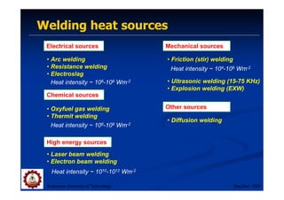
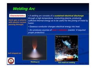
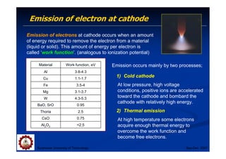
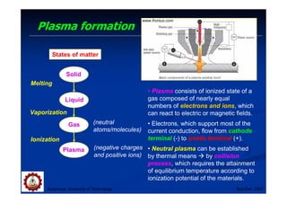
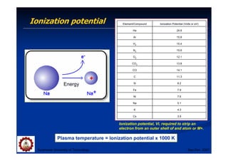
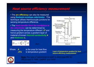
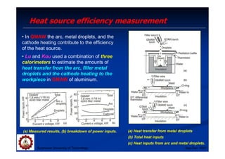
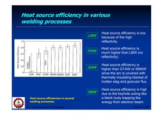
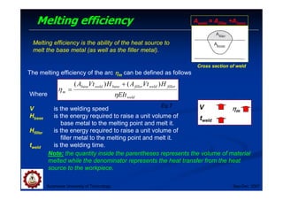
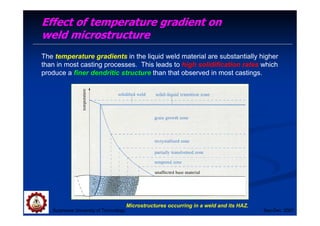
Heat flow in welding
Subjects of Interest
Suranaree University of Technology Sep-Dec 2007
• Heat sources
• Heat source and melting efficiency
• Analysis of heat flow in welding
• Effects of welding parameter
• Weld thermal simulator
Objectives
Objectives
• This chapter provides information of heat flow during
welding, which can strongly affect phase transformation,
microstructure, and properties of the welds.
• Students are required to indicate heat source and power
density used in different welding methods, which affect the
melting efficiency.
Suranaree University of Technology Sep-Dec 2007
Welding heat sources
Suranaree University of Technology Sep-Dec 2007
Electrical sources
Chemical sources
High energy sources
Mechanical sources
Other sources
• Arc welding
• Resistance welding
• Electroslag
• Oxyfuel gas welding
• Thermit welding
• Laser beam welding
• Electron beam welding
• Friction (stir) welding
• Ultrasonic welding (15-75 KHz)
• Explosion welding (EXW)
• Diffusion welding
Heat intensity ~ 1010-1012 Wm-2
Heat intensity ~ 106-108 Wm-2
Heat intensity ~ 104-106 Wm-2
Welding Arc
Suranaree University of Technology Sep-Dec 2007
• A welding arc consists of a sustained electrical discharge
through a high temperature, conducting plasma, producing
sufficient thermal energy as to be useful for the joining of metal by
fusion.
• Gaseous conductor changes electrical energy into heat.
• Arc produces sources of heat + radiation (careful  required
proper protection)
Welding arc Gas metal arc welding
http://en.wikipedia.org
Characteristics
(ionic gas or plasma
with electric current
passing through)
bell shaped arc
Emission of electron at cathode
Suranaree University of Technology Sep-Dec 2007
Emission of electrons at cathode occurs when an amount
of energy required to remove the electron from a material
(liquid or solid). This amount of energy per electron is
called ‘work function’. (analogous to ionization potential)
2.5
Al2O3
0.75
CsO
2.5
Thoria
0.95
BaO, SrO
4.3-5.3
W
3.1-3.7
Mg
3.5-4
Fe
1.1-1.7
Cu
3.8-4.3
Al
Work function, eV
Material Emission occurs mainly by two processes;
1) Cold cathode
2) Thermal emission
At low pressure, high voltage
conditions, positive ions are accelerated
toward the cathode and bombard the
cathode with relatively high energy.
At high temperature some electrons
acquire enough thermal energy to
overcome the work function and
become free electrons.
Plasma formation
Suranaree University of Technology Sep-Dec 2007
States of matter
Solid
Liquid
Gas
Plasma
Melting
Vaporization
Ionization
(neutral
atoms/molecules)
(negative charges
and positive ions)
• Plasma consists of ionized state of a
gas composed of nearly equal
numbers of electrons and ions, which
can react to electric or magnetic fields.
• Electrons, which support most of the
current conduction, flow from cathode
terminal (-) to anode terminal (+).
• Neutral plasma can be established
by thermal means  by collision
process, which requires the attainment
of equilibrium temperature according to
ionization potential of the materials.
www.fronius.com
Ionization potential
Suranaree University of Technology Sep-Dec 2007
Ionization potential, Vi, required to strip an
electron from an outer shell of and atom or M+.
3.9
Cs
4.3
K
5.1
Na
7.6
Ni
7.9
Fe
8.2
Si
11.3
C
14.1
CO
13.8
CO2
12.1
O2
15.6
N2
15.4
H2
15.8
Ar
24.6
He
Ionization Potential (Volts or eV)
Element/Compound
Plasma temperature = Ionization potential x 1000 K
Energy
Power in arc
Suranaree University of Technology Sep-Dec 2007
Arc area is mainly divided into
three zones;
1) Anode
2) Cathode
3) Plasma arc column
a
a IE
P =
c
c IE
P =
l
dl
dE
I
P arc
arc )
/
(
=
•The electrical power is dissipated in three
regions of the arc: anode, cathode and plasma
column.
•The area at cathode and anode has strong
effects on arc configuration, the flow of the
heat energy to the terminal  affecting shape
and depth of the fusion zone.
Note: Most heat goes to the
anode/cathode and most is lost
radially from the arc
Pa
Pc
Cathode -
Anode +
Power (Parc) Heat
Energy dissipation in the arc
Temperature in the arc and heat loss
Suranaree University of Technology Sep-Dec 2007
Plasma temperature contour in the arc
• The arc temperature ~ 5000-30,000 K
depending on the nature of plasma and
current.
• The arc temperature is determined by
measuring the spectral radiation
emitted.
www.geocities.com
Heat losses in the arc
• Energy losses by heat conduction
and convection, radiation and
diffusion.
• In Ar gas, radiation loss ~ 20%
while in other welding gas, radiation
loss 10%.
Note: The use of fluxing reduces radiation lost
Temp Radiation loss
Heat loss
Polarity
Suranaree University of Technology Sep-Dec 2007
There are three different types of current used in arc welding
1) Direct-Current Electrode Negative (DCEN)
2) Direct-Current Electrode Positive (DCEP)
3) Alternating current (AC)
Suranaree University of Technology Sep-Dec 2007
Direct-Current Electrode Negative (DCEN)
• Also called straight polarity.
• Electrons are emitted from the negative
tungsten electrode and accelerated while
travelling through the arc.
• Most commonly used in GTAW.
• Relatively narrow and deep weld pool is
produced due to high energy.
• DCEN in GMAW makes the arc unstable
and causes excessive spatter, large droplet
size of metal and the arcs forces the droplets
away from the workpiece.  This is due to a
low rate of electron emission from the negative
electrode.
Suranaree University of Technology Sep-Dec 2007
Direct-Current Electrode Positive (DCEP)
• Also called reverse polarity.
• The electrode is connected to the positive
terminal of the power source, therefore the
heating affect is now at the tungsten electrode
rather than the workpiece.  shallow weld  for
welding thin sheets.
• At low current in Ar, the size of the droplet ~ the
size of the electrode  Globular transfer.
• The droplet size is inversely proportional to the
current and the droplets are released at the rate
of a few per second.
• At above the critical current  the droplets are
released at the rate of hundreds per second
(spray mode).
• Positive irons clean off the oxide surface.
Surface cleaning action
Suranaree University of Technology Sep-Dec 2007
DCEP can be employed to clean the surface of the workpiece by knocking
off oxide films by the positive ions of the shielding gas.
Ex: cleaning of Al2O3 oxide film
(Tm ~2054oC) on aluminium to
make melting of the metal
underneath the oxide film easier.
Surface cleaning action in GTAW with
DC electrode positive.
Suranaree University of Technology Sep-Dec 2007
Alternating Current (AC)
• Reasonably good penetration and
oxide cleaning action can be both
obtained.
• Often used for welding aluminium
alloys.
Heat source efficiency
Suranaree University of Technology Sep-Dec 2007
In the case of arc welding, having a constant voltage E and a
constant current I, the arc efficiency can be expressed as;
EI
Q
EIt
Qt
t
Q
Qt
weld
weld
weld
al
no
weld
=
=
=
min
η Eq.2
In cases of electron beam and laser beam welding, Qnominal is the power
heat source of the electron beam and laser beam respectively.
The term, heat input per unit length of weld often refers to
V
EI
or
V
Q al
no
,
min
Eq.3
Where Qnominal or EI is the heat input
V is the welding speed
Qnominal / V is heat input per unit length of weld
Where Q is the rate of heat transfer
Qnominal is the heat input
tweld is the welding time
Heat source efficiency measurement
Suranaree University of Technology Sep-Dec 2007
• Heat source efficiency can be measured using
a calorimeter (by measuring the heat transfer
from the heat source to the workpiece and then to
the calorimeter).
• The temperature rise in the cooling water
(Tout-Tin) can be measured using thermocouples
or thermistors. Heat transfer from the workpiece
to the calorimeter is given by
dt
T
T
WC
dt
T
T
WC
Qt in
out
in
out
weld ∫ ∫ −
≈
−
=
α α
0 0
)
(
)
(
Eq.4
Where W is the mass flow rate of water
C is the specific heat of water
Tout is the outlet water temperature
Tin is the inlet water temperature
t is time
Note: This integral corresponds
to the shaded area, and can be
used to calculated the arc
efficiency η
η
η
η.
Heat source efficiency measurement
Suranaree University of Technology Sep-Dec 2007
• The arc efficiency can also be measured
using Seebeck envelope calorimeter. This
technique utilises thermocouple junctions for
sensing temperature difference.
• The heat transfer from the workpiece to
the calorimeter can be determined by
measuring the temperature different ∆
∆
∆
∆T and
hence gradient across a gradient layer of
material of known thermal conductivity k
and thickness L.
∫
∆
=
α
0
dt
L
T
k
A
Qtweld Eq.5
Where A is the area for heat flow
∆
∆
∆
∆T/L is temperature gradient
Note: this type of calorimeter is used to determine the arc
efficiencies in PAW, GMAW, and SAW.
Layer of temperature gradient for heat
source efficiency measurement.
Heat source efficiency measurement
Suranaree University of Technology Sep-Dec 2007
• In GMAW the arc, metal droplets, and the
cathode heating contribute to the efficiency
of the heat source.
• Lu and Kou used a combination of three
calorimeters to estimate the amounts of
heat transfer from the arc, filler metal
droplets and the cathode heating to the
workpiece in GMAW of aluminium.
(a) Heat transfer from metal droplets
(c) Heat inputs from arc and metal droplets.
(b) Total heat inputs
(a) Measured results, (b) breakdown of power inputs.
Heat source efficiency in various
welding processes
Suranaree University of Technology Sep-Dec 2007
LBW
Heat source efficiency is low
because of the high
reflectivity.
PAW
Heat source efficiency is
much higher than LBW (no
reflectivity).
EBW
Heat source efficiency is high
due to the keyhole acting like
a black body trapping the
energy from electron beam.
SAW
Heat source efficiency is
higher than GTAW or SMAW
since the arc is covered with
thermally insulating blanket of
molten slag and granular flux.
Heat source efficiencies in several
welding processes.
Melting efficiency
Suranaree University of Technology Sep-Dec 2007
The melting efficiency of the arc η
η
η
ηm can be defined as follows
weld
filler
weld
filler
base
weld
base
m
EIt
H
Vt
A
H
Vt
A
η
η
)
(
)
( +
=
Where
V is the welding speed
Hbase is the energy required to raise a unit volume of
base metal to the melting point and melt it.
Hfiller is the energy required to raise a unit volume of
filler metal to the melting point and melt it.
tweld is the welding time.
Eq.7
Note: the quantity inside the parentheses represents the volume of material
melted while the denominator represents the heat transfer from the heat
source to the workpiece.
η
η
η
ηm
V
tweld
Aweld = Afiller +Abase
Melting efficiency is the ability of the heat source to
melt the base metal (as well as the filler metal).
Cross section of weld
Melting efficiency
Suranaree University of Technology Sep-Dec 2007
(a) shallow welds of
lower melting
efficiency,
(b) (b) deeper weld of
higher melting
efficiency.
Aweld = Afiller +Abase
Low heat input
Low welding speed
High heat input
High welding speed
Power density distribution of heat source
Suranaree University of Technology Sep-Dec 2007
Power density distribution is influenced by
1) Electrode tip angle
2) Electrode tip geometry
Effect of electrode tip angle on shape and power
density distribution of gas-tungsten arc.
Blunter electrode
• Arc diameter
• Power density distribution
Sharp electrode
• Arc diameter
• Power density distribution
Effect of electrode tip angle on shape of
gas tungsten arc and power density
Suranaree University of Technology Sep-Dec 2007
Conical angle of
electrode tip
The arc becomes
more constricted
Analysis of heat flow in welding
Suranaree University of Technology Sep-Dec 2007
Heat or temperature distribution occurring during welding greatly affect
microstructure of the weld, hence, the weld properties
Temperature distribution round a typical weld
•The temperature-distance profile
shows that the heat source travels
along the weld in the direction A-A’ at
a constant speed.
• As the heat source moves on, the
cooling rates around the weld are very
high.
• A more intense heat source will give
a steeper profile and the HAZ, which
will be confined to a narrower region.
Effect of temperature gradient on
weld microstructure
Suranaree University of Technology Sep-Dec 2007
Microstructures occurring in a weld and its HAZ.
The temperature gradients in the liquid weld material are substantially higher
than in most casting processes. This leads to high solidification rates which
produce a finer dendritic structure than that observed in most castings.
Effect of welding parameters
Suranaree University of Technology Sep-Dec 2007
• Effect of heat input Q and welding
speed V on the weld pool.
• Effect of heat input on cooling rate.
• Effect of the power density
distribution of the heat source on the
weld shape.
• Heat sink effect of workpiece.
Suranaree University of Technology Sep-Dec 2007
Effect of heat input and welding
speed on the weld pool
• The shape and size of the weld pool is
significantly affected by heat input Q and
the welding speed V.
Heat input
Welding speed
The weld pool
becomes more
elongated.
Note: the cross indicates the
position of the electrode.
Suranaree University of Technology Sep-Dec 2007
Effect of heat input on cooling rate
Heat input per
unit length EI/V
Cooling rate
The cooling rate in ESW (high Q/V)
is much smaller than that in arc
welding.
Suranaree University of Technology Sep-Dec 2007
Effect of power density distribution
on weld shape
Power density
Weld penetration
Suranaree University of Technology Sep-Dec 2007
Heat sink effect of the workpiece
• The cooling rate increases with the
thickness of the workpiece due to
the heat sink effect.
• Thicker workpiece acts as a better
heat sink to cool the weld down.
Brass with a higher melting point than
that of aluminium is used as a heat sink
to increase the cooling rate in
aluminium welding.
Blass heat sink is clamped behind
aluminium to be welded.
References
References
• Kou, S., Welding metallurgy, 2nd edition, 2003, John Willey and
Sons, Inc., USA, ISBN 0-471-43491-4.
• Gourd, L.M., Principles of welding technology, 3rd edition, 1995,
Edward Arnold, ISBN 0 340 61399 8.
Suranaree University of Technology Sep-Dec 2007

02_Heatflowinwelding and joining process

  • 1.
    Heat flow inwelding Heat flow in welding Subjects of Interest Suranaree University of Technology Sep-Dec 2007 • Heat sources • Heat source and melting efficiency • Analysis of heat flow in welding • Effects of welding parameter • Weld thermal simulator
  • 2.
    Objectives Objectives • This chapterprovides information of heat flow during welding, which can strongly affect phase transformation, microstructure, and properties of the welds. • Students are required to indicate heat source and power density used in different welding methods, which affect the melting efficiency. Suranaree University of Technology Sep-Dec 2007
  • 3.
    Welding heat sources SuranareeUniversity of Technology Sep-Dec 2007 Electrical sources Chemical sources High energy sources Mechanical sources Other sources • Arc welding • Resistance welding • Electroslag • Oxyfuel gas welding • Thermit welding • Laser beam welding • Electron beam welding • Friction (stir) welding • Ultrasonic welding (15-75 KHz) • Explosion welding (EXW) • Diffusion welding Heat intensity ~ 1010-1012 Wm-2 Heat intensity ~ 106-108 Wm-2 Heat intensity ~ 106-108 Wm-2 Heat intensity ~ 104-106 Wm-2
  • 4.
    Welding Arc Suranaree Universityof Technology Sep-Dec 2007 • A welding arc consists of a sustained electrical discharge through a high temperature, conducting plasma, producing sufficient thermal energy as to be useful for the joining of metal by fusion. • Gaseous conductor changes electrical energy into heat. • Arc produces sources of heat + radiation (careful required proper protection) Welding arc Gas metal arc welding http://en.wikipedia.org Characteristics (ionic gas or plasma with electric current passing through) bell shaped arc
  • 5.
    Emission of electronat cathode Suranaree University of Technology Sep-Dec 2007 Emission of electrons at cathode occurs when an amount of energy required to remove the electron from a material (liquid or solid). This amount of energy per electron is called ‘work function’. (analogous to ionization potential) 2.5 Al2O3 0.75 CsO 2.5 Thoria 0.95 BaO, SrO 4.3-5.3 W 3.1-3.7 Mg 3.5-4 Fe 1.1-1.7 Cu 3.8-4.3 Al Work function, eV Material Emission occurs mainly by two processes; 1) Cold cathode 2) Thermal emission At low pressure, high voltage conditions, positive ions are accelerated toward the cathode and bombard the cathode with relatively high energy. At high temperature some electrons acquire enough thermal energy to overcome the work function and become free electrons.
  • 6.
    Plasma formation Suranaree Universityof Technology Sep-Dec 2007 States of matter Solid Liquid Gas Plasma Melting Vaporization Ionization (neutral atoms/molecules) (negative charges and positive ions) • Plasma consists of ionized state of a gas composed of nearly equal numbers of electrons and ions, which can react to electric or magnetic fields. • Electrons, which support most of the current conduction, flow from cathode terminal (-) to anode terminal (+). • Neutral plasma can be established by thermal means by collision process, which requires the attainment of equilibrium temperature according to ionization potential of the materials. www.fronius.com
  • 7.
    Ionization potential Suranaree Universityof Technology Sep-Dec 2007 Ionization potential, Vi, required to strip an electron from an outer shell of and atom or M+. 3.9 Cs 4.3 K 5.1 Na 7.6 Ni 7.9 Fe 8.2 Si 11.3 C 14.1 CO 13.8 CO2 12.1 O2 15.6 N2 15.4 H2 15.8 Ar 24.6 He Ionization Potential (Volts or eV) Element/Compound Plasma temperature = Ionization potential x 1000 K Energy
  • 8.
    Power in arc SuranareeUniversity of Technology Sep-Dec 2007 Arc area is mainly divided into three zones; 1) Anode 2) Cathode 3) Plasma arc column a a IE P = c c IE P = l dl dE I P arc arc ) / ( = •The electrical power is dissipated in three regions of the arc: anode, cathode and plasma column. •The area at cathode and anode has strong effects on arc configuration, the flow of the heat energy to the terminal affecting shape and depth of the fusion zone. Note: Most heat goes to the anode/cathode and most is lost radially from the arc Pa Pc Cathode - Anode + Power (Parc) Heat Energy dissipation in the arc
  • 9.
    Temperature in thearc and heat loss Suranaree University of Technology Sep-Dec 2007 Plasma temperature contour in the arc • The arc temperature ~ 5000-30,000 K depending on the nature of plasma and current. • The arc temperature is determined by measuring the spectral radiation emitted. www.geocities.com Heat losses in the arc • Energy losses by heat conduction and convection, radiation and diffusion. • In Ar gas, radiation loss ~ 20% while in other welding gas, radiation loss 10%. Note: The use of fluxing reduces radiation lost Temp Radiation loss Heat loss
  • 10.
    Polarity Suranaree University ofTechnology Sep-Dec 2007 There are three different types of current used in arc welding 1) Direct-Current Electrode Negative (DCEN) 2) Direct-Current Electrode Positive (DCEP) 3) Alternating current (AC)
  • 11.
    Suranaree University ofTechnology Sep-Dec 2007 Direct-Current Electrode Negative (DCEN) • Also called straight polarity. • Electrons are emitted from the negative tungsten electrode and accelerated while travelling through the arc. • Most commonly used in GTAW. • Relatively narrow and deep weld pool is produced due to high energy. • DCEN in GMAW makes the arc unstable and causes excessive spatter, large droplet size of metal and the arcs forces the droplets away from the workpiece. This is due to a low rate of electron emission from the negative electrode.
  • 12.
    Suranaree University ofTechnology Sep-Dec 2007 Direct-Current Electrode Positive (DCEP) • Also called reverse polarity. • The electrode is connected to the positive terminal of the power source, therefore the heating affect is now at the tungsten electrode rather than the workpiece. shallow weld for welding thin sheets. • At low current in Ar, the size of the droplet ~ the size of the electrode Globular transfer. • The droplet size is inversely proportional to the current and the droplets are released at the rate of a few per second. • At above the critical current the droplets are released at the rate of hundreds per second (spray mode). • Positive irons clean off the oxide surface.
  • 13.
    Surface cleaning action SuranareeUniversity of Technology Sep-Dec 2007 DCEP can be employed to clean the surface of the workpiece by knocking off oxide films by the positive ions of the shielding gas. Ex: cleaning of Al2O3 oxide film (Tm ~2054oC) on aluminium to make melting of the metal underneath the oxide film easier. Surface cleaning action in GTAW with DC electrode positive.
  • 14.
    Suranaree University ofTechnology Sep-Dec 2007 Alternating Current (AC) • Reasonably good penetration and oxide cleaning action can be both obtained. • Often used for welding aluminium alloys.
  • 15.
    Heat source efficiency SuranareeUniversity of Technology Sep-Dec 2007 In the case of arc welding, having a constant voltage E and a constant current I, the arc efficiency can be expressed as; EI Q EIt Qt t Q Qt weld weld weld al no weld = = = min η Eq.2 In cases of electron beam and laser beam welding, Qnominal is the power heat source of the electron beam and laser beam respectively. The term, heat input per unit length of weld often refers to V EI or V Q al no , min Eq.3 Where Qnominal or EI is the heat input V is the welding speed Qnominal / V is heat input per unit length of weld Where Q is the rate of heat transfer Qnominal is the heat input tweld is the welding time
  • 16.
    Heat source efficiencymeasurement Suranaree University of Technology Sep-Dec 2007 • Heat source efficiency can be measured using a calorimeter (by measuring the heat transfer from the heat source to the workpiece and then to the calorimeter). • The temperature rise in the cooling water (Tout-Tin) can be measured using thermocouples or thermistors. Heat transfer from the workpiece to the calorimeter is given by dt T T WC dt T T WC Qt in out in out weld ∫ ∫ − ≈ − = α α 0 0 ) ( ) ( Eq.4 Where W is the mass flow rate of water C is the specific heat of water Tout is the outlet water temperature Tin is the inlet water temperature t is time Note: This integral corresponds to the shaded area, and can be used to calculated the arc efficiency η η η η.
  • 17.
    Heat source efficiencymeasurement Suranaree University of Technology Sep-Dec 2007 • The arc efficiency can also be measured using Seebeck envelope calorimeter. This technique utilises thermocouple junctions for sensing temperature difference. • The heat transfer from the workpiece to the calorimeter can be determined by measuring the temperature different ∆ ∆ ∆ ∆T and hence gradient across a gradient layer of material of known thermal conductivity k and thickness L. ∫ ∆ = α 0 dt L T k A Qtweld Eq.5 Where A is the area for heat flow ∆ ∆ ∆ ∆T/L is temperature gradient Note: this type of calorimeter is used to determine the arc efficiencies in PAW, GMAW, and SAW. Layer of temperature gradient for heat source efficiency measurement.
  • 18.
    Heat source efficiencymeasurement Suranaree University of Technology Sep-Dec 2007 • In GMAW the arc, metal droplets, and the cathode heating contribute to the efficiency of the heat source. • Lu and Kou used a combination of three calorimeters to estimate the amounts of heat transfer from the arc, filler metal droplets and the cathode heating to the workpiece in GMAW of aluminium. (a) Heat transfer from metal droplets (c) Heat inputs from arc and metal droplets. (b) Total heat inputs (a) Measured results, (b) breakdown of power inputs.
  • 19.
    Heat source efficiencyin various welding processes Suranaree University of Technology Sep-Dec 2007 LBW Heat source efficiency is low because of the high reflectivity. PAW Heat source efficiency is much higher than LBW (no reflectivity). EBW Heat source efficiency is high due to the keyhole acting like a black body trapping the energy from electron beam. SAW Heat source efficiency is higher than GTAW or SMAW since the arc is covered with thermally insulating blanket of molten slag and granular flux. Heat source efficiencies in several welding processes.
  • 20.
    Melting efficiency Suranaree Universityof Technology Sep-Dec 2007 The melting efficiency of the arc η η η ηm can be defined as follows weld filler weld filler base weld base m EIt H Vt A H Vt A η η ) ( ) ( + = Where V is the welding speed Hbase is the energy required to raise a unit volume of base metal to the melting point and melt it. Hfiller is the energy required to raise a unit volume of filler metal to the melting point and melt it. tweld is the welding time. Eq.7 Note: the quantity inside the parentheses represents the volume of material melted while the denominator represents the heat transfer from the heat source to the workpiece. η η η ηm V tweld Aweld = Afiller +Abase Melting efficiency is the ability of the heat source to melt the base metal (as well as the filler metal). Cross section of weld
  • 21.
    Melting efficiency Suranaree Universityof Technology Sep-Dec 2007 (a) shallow welds of lower melting efficiency, (b) (b) deeper weld of higher melting efficiency. Aweld = Afiller +Abase Low heat input Low welding speed High heat input High welding speed
  • 22.
    Power density distributionof heat source Suranaree University of Technology Sep-Dec 2007 Power density distribution is influenced by 1) Electrode tip angle 2) Electrode tip geometry Effect of electrode tip angle on shape and power density distribution of gas-tungsten arc. Blunter electrode • Arc diameter • Power density distribution Sharp electrode • Arc diameter • Power density distribution
  • 23.
    Effect of electrodetip angle on shape of gas tungsten arc and power density Suranaree University of Technology Sep-Dec 2007 Conical angle of electrode tip The arc becomes more constricted
  • 24.
    Analysis of heatflow in welding Suranaree University of Technology Sep-Dec 2007 Heat or temperature distribution occurring during welding greatly affect microstructure of the weld, hence, the weld properties Temperature distribution round a typical weld •The temperature-distance profile shows that the heat source travels along the weld in the direction A-A’ at a constant speed. • As the heat source moves on, the cooling rates around the weld are very high. • A more intense heat source will give a steeper profile and the HAZ, which will be confined to a narrower region.
  • 25.
    Effect of temperaturegradient on weld microstructure Suranaree University of Technology Sep-Dec 2007 Microstructures occurring in a weld and its HAZ. The temperature gradients in the liquid weld material are substantially higher than in most casting processes. This leads to high solidification rates which produce a finer dendritic structure than that observed in most castings.
  • 26.
    Effect of weldingparameters Suranaree University of Technology Sep-Dec 2007 • Effect of heat input Q and welding speed V on the weld pool. • Effect of heat input on cooling rate. • Effect of the power density distribution of the heat source on the weld shape. • Heat sink effect of workpiece.
  • 27.
    Suranaree University ofTechnology Sep-Dec 2007 Effect of heat input and welding speed on the weld pool • The shape and size of the weld pool is significantly affected by heat input Q and the welding speed V. Heat input Welding speed The weld pool becomes more elongated. Note: the cross indicates the position of the electrode.
  • 28.
    Suranaree University ofTechnology Sep-Dec 2007 Effect of heat input on cooling rate Heat input per unit length EI/V Cooling rate The cooling rate in ESW (high Q/V) is much smaller than that in arc welding.
  • 29.
    Suranaree University ofTechnology Sep-Dec 2007 Effect of power density distribution on weld shape Power density Weld penetration
  • 30.
    Suranaree University ofTechnology Sep-Dec 2007 Heat sink effect of the workpiece • The cooling rate increases with the thickness of the workpiece due to the heat sink effect. • Thicker workpiece acts as a better heat sink to cool the weld down. Brass with a higher melting point than that of aluminium is used as a heat sink to increase the cooling rate in aluminium welding. Blass heat sink is clamped behind aluminium to be welded.
  • 31.
    References References • Kou, S.,Welding metallurgy, 2nd edition, 2003, John Willey and Sons, Inc., USA, ISBN 0-471-43491-4. • Gourd, L.M., Principles of welding technology, 3rd edition, 1995, Edward Arnold, ISBN 0 340 61399 8. Suranaree University of Technology Sep-Dec 2007