Download to read offline
![International Research Journal of Engineering and Technology (IRJET) e-ISSN: 2395-0056
Volume: 04 Issue: 12 | Dec-2017 www.irjet.net p-ISSN: 2395-0072
© 2017, IRJET | Impact Factor value: 6.171 | ISO 9001:2008 Certified Journal | Page 262
required for the module. (XL = 2ПfL) Inductor blocks high
frequency signals and allows low frequency signals.
8.1. Operation Principal:
In the design of PLC transceiversmodem,channelimpedance
is important like that other networks. In order to maximum
power transfer between the PLC modem and the power line,
modem output impedance and the power line input
impedance should be matched. Therefore for the modem
design, impedance of the power line must be known.
In order to calculate the impedance offered by power line
communication modem we have general formula
|Z| =0.005*f^0.63
Where
|Z|= Impedance
f = Carrier frequency
In our experiment we use KQ 330F modem which uses
carrier frequency 120 kHz.
So the impedance Z is
|Z| =0.005*(120*10³) ^0.63
Therefore |Z| = 8Ω.
However the input (and output) impedance varies in time,
with different loads and locations. It can be as low as milli Ω
and as high as several thousands of Ω. So there is a chance of
occurring impedance mismatch. Use of filters will stabilize
the network.
9.APPLICATIONS
• Monitoring: measurements on equipment and network
elements, AMR and DSM services, etc.
• Operational services: remote control, emergency signals,
security systems, messaging, etc.
• Home and Industrial Automation
• Internet access.
10. ADVANTAGES
• It uses existing electrical wiring.
• It is inexpensive.
• It provides Flexibility & Stability.
• It's easy to install.
• PLC solution is a complementary or alternative
solution to traditional fixed line networks,wireless
networks.
• Every room of a typical house has several electrical
outlets.
11. CONCLUSION
Tests in PLC have been carried out in 20 countries in around
1500 residences. The mapping of results has been extremely
positive and forecasts a great demand for the system. Power
line communication technology is definitely an exciting
alternative to connect internet via phone and modem.
Though this technology is not commercially available yet, it
should be availableoverotherbroadbandtechnologiesdueto
relatively low cost of its local loop. Moreover, its high speed
will provide internet access, local phone, and long distance
service to customers.
REFERENCES
1) Power line communication by John Wiley
volume 16 issue5
2) Broadband is Power: internet access through power
line network, IEEE Communications Magazine.
3) Hendrik C Ferreira and Olaf Hooijen, ―Power Line
Communications: An Overview, Transactions of the S.A
Institute of Electrical Engineers
4) Comm. Eur. Union, “Smart grids technology platform.
European technology platform for the electricity
networks of the future.” Belgium, EUR 22040, 2006.
[Online]. Available: www.smartgrids.eu
5) N. Jenkins, J. B. Ekanayake, and C. Strbac, Distributed
Generation. London, UK: IET Publ., 2010.
6) D. Coll-Mayor, M. Paget, and E. Lightner, “Future
intelligent power grids: Analysis of the vision in the
European Union and the United States,” Energy Policy,
vol. 354, pp. 2453–2465, 2007.
7) S. Galli, A. Scaglione, and Z.Wang, “For the grid and
through the grid: Theroleof powerlinecommunications
in the smart grid,” Proc.IEEE, vol. 99, no. 6, pp. 998–
1027, Jun. 2011.
8) S. Grenard, O. Devaux, O.Carre, & O.Huet, “Power
steering,” IEEE Power Energy Mag., vol. 9, no. 5, pp. 43–
51, Sep./Oct. 2011.
9) S. Roy, D. Nordell, and S. S. Venkata, “Lines of
communication,” IEEE Power Energy Mag., vol. 9, no. 5,
pp. 65–73, Sep./Oct. 2011.
10) U.S. Dept. Energy, “A systems view of the modern
grid: Integrated communications,” Feb. 2007.
11) V. C. Gungor and F. C. Lambert, “A survey on
communication networks for electric system
automation,” Comput. Netw. vol. 50, pp.877– 897,2006.
12) IEEE Standard for Broadband over Power Line
Networks: Medium Access Control and Physical Layer
Specifications, IEEE Standard 1901–2010, Sep. 2010.
13) A. Ametani, “A general formulation of impedance and
admittance of cables,” IEEE Trans. Power App. Syst., vol.
PAS-99, no. 3, pp. 902–910, May 1980.
14) Y. Xiaoxian, Z. Tao, Z. Baohui, N. H. Xu,L.Changxin,and
T. Lixi,“Investigation of transmission properties on 10-
kV medium- voltage.](https://image.slidesharecdn.com/irjet-v4i1248-180110072949/75/Application-of-NarrowBand-Power-Line-Communication-in-Medium-Voltage-Smart-Distribution-Grid-4-2048.jpg)

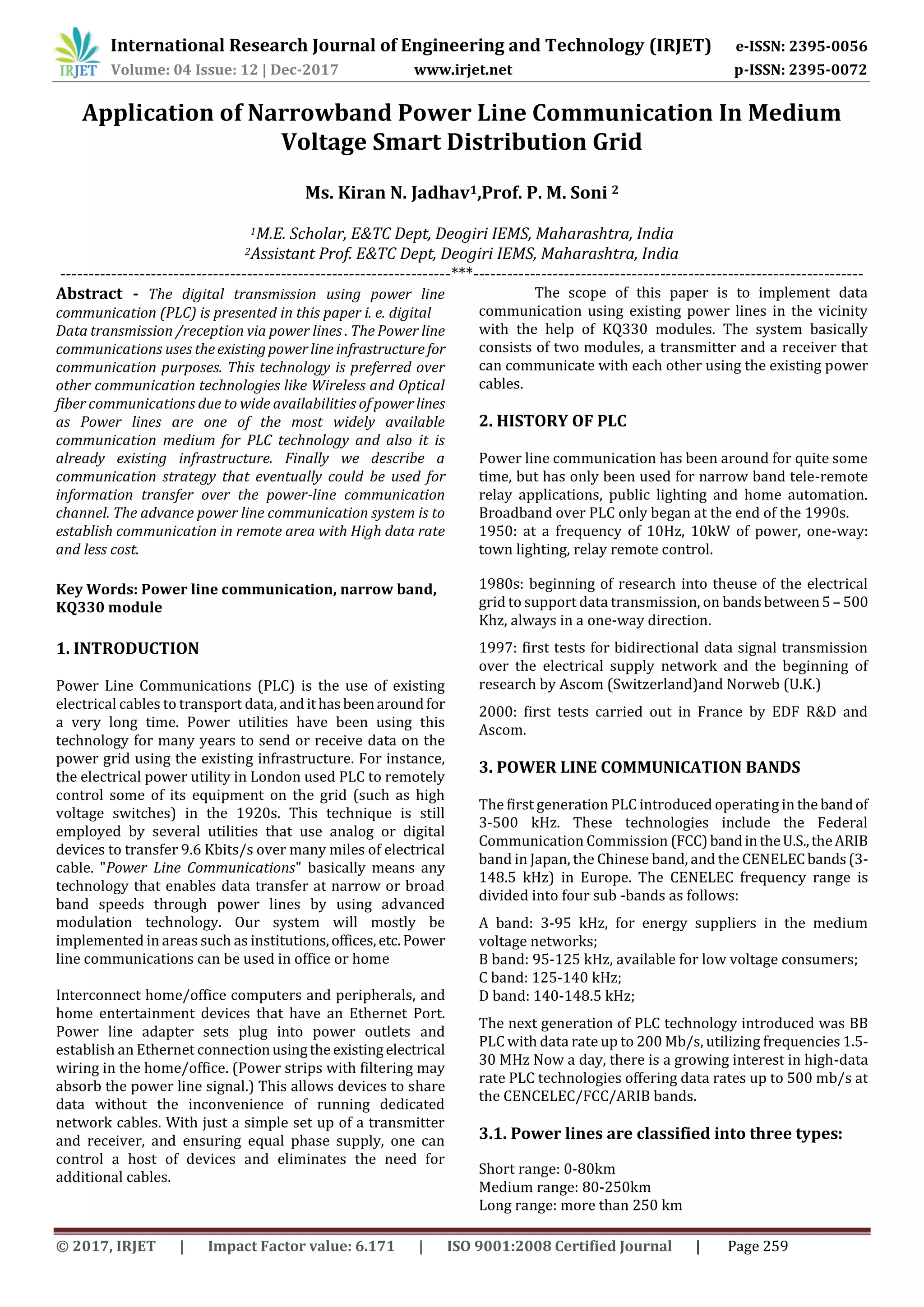
The document discusses applying narrowband power line communication technology in medium voltage smart distribution grids. It describes using existing power lines to transmit data using modulation techniques. A system is proposed using KQ330 modules consisting of a transmitter and receiver to communicate over power lines. The technology can be used for applications like monitoring equipment, automation, and internet access because power lines provide a widespread communication medium at low cost compared to other options. Challenges include impedance matching the communication modules to the power lines.