Downloaded 10 times

![A. Data Acquisition
This section is responsible for acquiring power
consumption data such as Line Voltage, and Line Current of
the appliance/nodes. The data is obtained through metrology
sensors, and given to a moderate resolution ADC. This data is
sent to the Power Hub over the power lines, where the data is
processed to reveal details such as power factor, etc.
The modulator, as shown in [1], doesn’t require a carrier
input, phase shifter, or a switch circuit as in traditional BPSK
Modulators. The modulator consists of a Voltage Controlled
Current Source (VCCS), a resonator and a limiting amplifier.
B. Priority Control
Priority Control allows the client to set priority of operation
of the appliances. These priorities would be followed to
switch off appliances during power cuts, so that the basic
needs of a consumer are uninterrupted.
C. Control Block
It performs switching of appliances according to
instructions issued by the Power Hub. It consists of AC
switching elements such as TRIAC, controlled by a
microcontroller.
D. Network Interface
Network Interface provides a physical link between the
network and the Slave. It consists of a Power Line modem,
interfaced to the serial interface of the microcontroller through
an optical isolator.
IV. SYSTEM IMPLEMENTATION
The Half-Duplex communication link would be established
through the Power Line Modem on the physical layer. The
functional block diagram is as shown in figure 4.
Figure 5. Switched Resonator BPSK modulator [1]
The VCCS, made by A, Q, and R, produces the NRZ
current pulse stream and injects such a signal into the LC
resonant circuit. If the resonant frequency f, is an integral time
of the bit rate, the resonator output voltage will be a BPSK
signal. By adding a comparator or limiting amplifier following
the resonator, we can compensate for the amplitude decay and
still maintain the phase reversal. [1]
B. Notch Filter
The Notch Filter has been employed to protect the modem
from large power at lower frequencies, in the Power Lines.
The design requires a band-stop filter, with stop-band ranging
from 40 Hz to 300Hz, and pass band extending to higher
frequencies of upto 2 MHz. “The intrinsic high- frequency
limitations of the low-frequency notch circuit are overcome by
means of a coordinated parallel high-frequency path. The
combination of the two is capable of the extremely wide
frequency response.” [2]
Figure 4. Functional Block Diagram of Modem
Each functional block of the modem can be explained as
below.
A. BPSK Modulator
The modulation scheme employs a switched-resonator
BPSK modulator. The bit rate and carrier frequency have
experimentally been reported as 2.5 Mbit/s, at 5 MHz,
respectively. [1]
Figure 6. Symmetrical Twin-Tee Notch Filter
According to [2], the notch filter can be realized in three
topologies, Resistive-Branch Notch Filter, Capacitive-Branch
Notch Filter and Twin- Tee Notch Filter. Amongst the three
topologies, a symmetrical Twin-Tee design stands
intermediate between the other two topologies, and is suitable
for a moderate bandwidth with a simple design.](https://image.slidesharecdn.com/architectureforsmartgridbasedconsumerendsolution-131115065818-phpapp01/85/Architecture-for-Smart-Grid-based-Consumer-End-Solution-3-320.jpg)
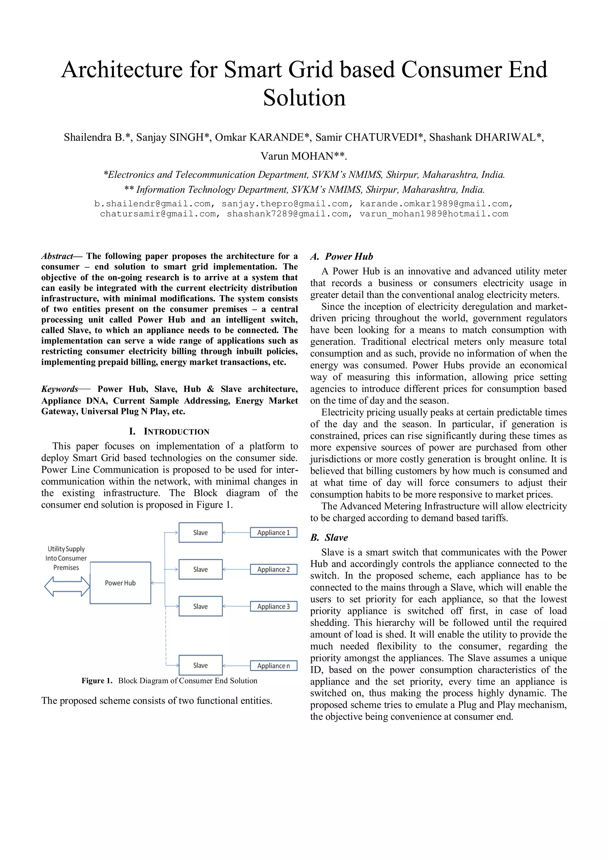
![Figure 9. Hub to Slave Transmission Schema
Figure 7. Frequency response simulation results of symmetrical Twin Tee
notch filter
C. BPSK Demodulator
BPSK Demodulation can be achieved through several
techniques, such as Squaring Loop and the COSTAS Loop.
However, the main problem of the squaring loop design
is that squaring devices are hard to implement using
analog circuitry [4]. Due to higher power consumption and
inferior tracking range of COSTAS Loop, low power BPSK
Demodulator architecture proposed in [3] would be utilized in
the modem. The block diagram of the demodulator is shown
in figure 7.
This choice is supported by performance analysis in [5],
with respect to coding, modulation types
and the
presence/absence of interleaving is depicted by BER vs.
SNR diagrams and complexity tables. “We observe that a
simple block code like Hamming (7, 4) with correction
capability of one error per code word produces much better
results compared to the uncoded transmission. Cyclic Golay
Code (23, 12) offers a much better performance, while
Convolutional Coding is even better, reaching a BER of 2x10⁴
at less than 35dB.” [5]
Time Division Multiple Access (TDMA) has been adopted
for communication between Slave and Hub. This approach
yields the advantage of working with a single carrier and
minimum hardware complexities. Power consumption pattern
of appliances in the form of Voltage, Current and Phase
difference will be sent from the Slave to Hub at regular time
intervals from the Slave within fixed time frames. To avoid
Inter-Symbol Interference, a Guard Frame is introduced
between consequent frames from the numerous Slaves.
VI. NOVEL ADDRESSING METHOD
The demodulator consists of Phase-Frequency detector
followed by Charge Pump PLL, which theoretically has an
infinite tracking range. [3] This stage is followed by a trigger
& hold circuit.
A. Current Sample Based Approach
A novel approach for assigning addresses/IDs to the Slaves
for the purpose of communication has been proposed. When
any particular device is switched on, the first line current
sample obtained from it is unique, if acquired using a high
resolution A/D converter. Suppose the sample is acquired
using an 8-bit ADC, the sample would consist of 256
quantums. The probability of these 256 quantums being
identical is unlikely even for identical devices of the same
manufacturer. The Slave acquires this sample and
communicates it to the Hub.
The Hub checks its database for ambiguities with the ID’s
of existing online appliances. In absence of any ambiguities
the ID is assigned to the Slave in question. If a rare conflict is
encountered the Hub resolves it by adding a predetermined
value to the ID until it becomes unique.
This kind of approach automates the address acquisition by
the Slave. The process requires no additional computation and
works on the existing data. The ID is lost as soon as the
appliance is switched off, thus keeping the process highly
dynamic. The emphasis of the approach is to achieve
Universal Plug N Play for Slaves.
V. COMMUNICATION SCHEMA
The communication scheme employs CDMA to transmit
BPSK modulated data over power lines for the
communication from Hub to Slave which can be shown as in
figure 9.
B. Appliance DNA
We propose a method to obtain signatures of appliances.
These signatures are preserved in the database even when the
appliance goes offline. The idea is based on the fact that every
appliance when manufactured have some non-uniformities, or
defects that do not reflect in the normal operation but become
Figure 8. . Low Power BPSK demodulator. [3]](https://image.slidesharecdn.com/architectureforsmartgridbasedconsumerendsolution-131115065818-phpapp01/85/Architecture-for-Smart-Grid-based-Consumer-End-Solution-4-320.jpg)
![prevalent at microscopic and nanoscopic levels. If these nonuniformities can somehow be reflected in the power
consumption pattern of the appliance, they can be treated as a
unique signature of the particular appliance. Further research
is in progress to make this approach acceptable universally.
VII.
APPLICATION SCENARIOS
A. Smart Grid Technologies
1) Device Management: In countries where demand of
power exceeds generation, power cuts are a major problem in
residential sectors, Small & Medium Enterprises (SMEs).
Such scenarios can be easily manipulated with the help of the
proposed architecture. As the architecture states a provision
for specifying priority of operation of each appliance, during
percentage power cuts or higher tariff rates, the Hub itself
switches off the low priority appliances, without interrupting
the essential electricity needs of the user. Thus the Hub and
Slave architecture provides the platform to regulate monthly
tariffs and efficient use of energy.
2) Prepaid Power: Prepaid tariffs can be implemented
using the above architecture. This can be customized to daily,
weekly or monthly tariff plans. The user can buy the power
credits beforehand depending on the budget. The Hub will
alert the user when the available power credits fall below a
certain level. This will help the user to choose an economic
approach towards energy consumption.
3) Energy Market Transaction: The proposed architecture
provides us a platform for regulated Energy transactions
between the Consumer and the Grid. The consumers targeted
here are households and SMEs capable of producing power
through Solar Panels, Boilers, Furnaces, etc. but not being
able to store it. These consumers can transact the excess
power with the Grid for energy credits. This will help the Grid
to tap energy from discrete resources which would have
otherwise been wasted.
Power Hub can act as a gateway to transact with the Grid.
Many Power Hubs can communicate amongst each other to
establish an Open Energy Market, wherein a consumer can
buy power from multiple sources, creating a competitive
scenario.
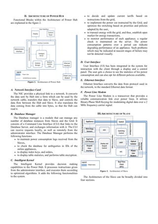
Figure 10 depicts a typical case wherein a customer has
excessive energy which can be transacted with the Grid or
other customers.
The Grid has set a selling price per unit for particular
duration. Let Me be the minimum price per unit. The Grid
would always be available to buy energy at this cost. This
price would be logically set by the Grid, keeping in mind the
profit margins to the customer after cost of production. If one
has energy resources to produce energy then one would
preferably look out for other customers willing to buy the
energy at the cost of x which lies between the graph of unit 1
and unit 0.25.
Apart from power producing clients, passive consumers
can also participate in energy transactions, by trading their
power credits with other users, for an amiable price. Thus,
both the Grid, and customers would be benefited by such an
open energy market.
B. Other Applications
1) Breakdown Management: The above architecture can
be effectively employed to centrally monitor performance of
machines connected in a production plant. The database
maintained in the Power Hub can be used to detect gradual
increase in power consumption of a machine over a period.
This performance can be analyzed at the Power Hub to reveal
machines that need immediate attention. Such an analysis can
help to identify degradation at an early stage which is
otherwise not visually detectable until a complete breakdown
of the machine occurs. In the presence of redundant machines,
the servicing can be scheduled without disturbing the
production routine.
2) Power Factor Correction: Power factor correction at
appliance level can reduce load on utility to a considerable
extent. Power factor can be corrected by the Slave with use of
some additional hardware specified in [6]. This keeps the
current and voltage in phase with each other, and reduces total
harmonic distortion.
VIII. CONCLUSIONS
The proposed architecture can be effectively deployed for
implementing Smart Grid based technologies on the consumer
premises. This paper reflects the new era of smart platforms
for implementing power management policies. The
architecture and hardware can also be scaled to increase the
network throughput, and can be integrated with Home Area
Networks for providing other services such as IPTV,
Broadband over Power Lines, Home Automation, etc.
REFERENCES
[1]
[2]
[3]
[4]
Figure 10. Typical Energy Market Scenario
Juin-Hung Chen and Hen-Wai Tsao, BPSK modulator using VCCS and
resonator without carrier signal and balance modulator, IEE
Electronics Letters Online No: 19970885, June 2, 1997.
LUIGI M. MILLANTA AND MAURO M. FORTI , A Notch-Filter
Network for Wide-Band Measurements of Transient Voltages on the
Power Line, IEEE TRANSACTIONS ON ELECTROMAGNETIC
COMPATIBILITY, VOL. 31 NO. 3. AUGUST 1989.
Zhenying Luo and Sameer Sonkusale, A Novel Low Power BPSK
Demodulator, Circuits and Systems I: Regular Papers, IEEE
Transactions , Volume: 55 , Issue: 6, 2008.
Roland E. Best, “Phase-Locked Loops - Design, Simulation, and
Applications”, 5th Edition, McGraw-Hill .](https://image.slidesharecdn.com/architectureforsmartgridbasedconsumerendsolution-131115065818-phpapp01/85/Architecture-for-Smart-Grid-based-Consumer-End-Solution-5-320.jpg)
![[5]
[6]
P. L. Katsis, G. D. Papadopoulos and F.-N. Pavlidou, Coded MCCDMA Systems for Power Line Communications, Telecommunications
in modern satellite, cable and broadcasting service, TELSIKS 2003, 6th
international conference, 1-3 October, 2003.
AVR433: Power Factor Corrector (PFC) with AT90PWM2 Retriggable High Speed PSC, Atmel Application notes http://www.atmel.com/dyn/resources/prod_documents/doc7628.pdf](https://image.slidesharecdn.com/architectureforsmartgridbasedconsumerendsolution-131115065818-phpapp01/85/Architecture-for-Smart-Grid-based-Consumer-End-Solution-6-320.jpg)

The document proposes an architecture for a smart grid solution at the consumer end. It consists of two main components: 1. A Power Hub, which is an advanced utility meter that records electricity usage details. It communicates with Slaves and implements functions like time-based pricing, load shedding policies, and energy market transactions. 2. Slaves, which are smart switches that connect appliances and control them based on instructions from the Power Hub. Slaves assume unique IDs for connected appliances. The architecture aims to integrate with existing infrastructure using power line communication between the Hub and Slaves. This allows for applications like prepaid billing, demand response, and a flexible load management system.


![[IJET V2I3P5] Authors: Jamuna H G, Shobha Hugar](https://cdn.slidesharecdn.com/ss_thumbnails/ijet-v2i3p5-160609051906-thumbnail.jpg?width=640&height=640&fit=bounds)