Download to read offline

![International Research Journal of Engineering and Technology (IRJET) e-ISSN: 2395-0056
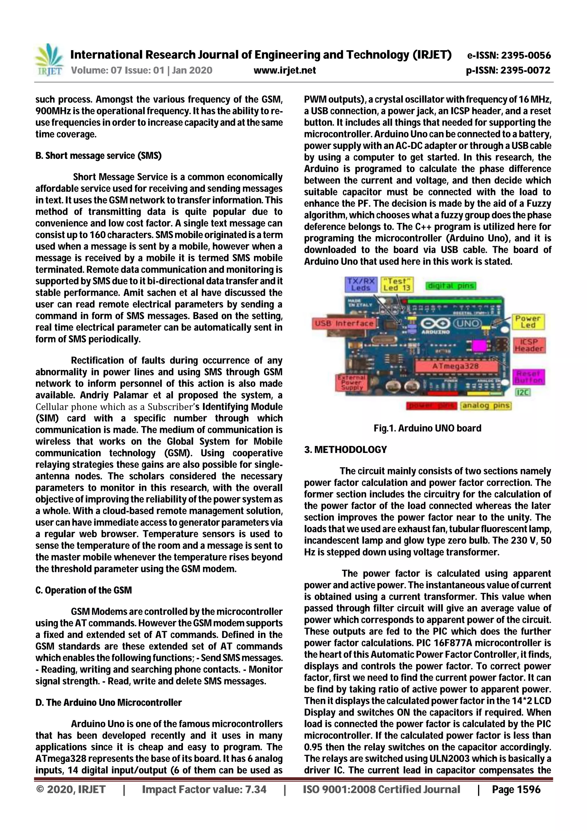
Volume: 07 Issue: 01 | Jan 2020 www.irjet.net p-ISSN: 2395-0072
© 2020, IRJET | Impact Factor value: 7.34 | ISO 9001:2008 Certified Journal | Page 1597
corresponding current lag which is usually present in loads.
Hence the phase difference between the current and voltage
will be reduced.
Fig. 2 Block Diagram of the system
4. CONCLUSION
It can be concluded that power factor correction
techniques can be applied to the industries, power systems
and also households to make them stable so that the system
becomes stable and efficiency of the system increases. The
use of microcontroller reduces the costs. Due to use of
microcontroller multiple parameters can be controlled at a
time and the use of extra hardwares such as timer, RAM,
ROM and input output ports reduces. The occurrences of
faults were displayed and the message was sent through the
GSM network over to the utility mobile phone. A bi-
directional communication was established as the system
was able to receive command from the utility phone to set a
short circuit limit.
REFERENCES
[1] Md. Raju, Ahmed M. J. Alam, Power Factor
Improvement by Pulse Width Modulated Switched
Single Capacitor, IEEE Proceedings of India
International Conference on Power Electronics,
Chennai, December 2006, pp. 212 – 215.
[2] T.W. Kim, J.H. Choi and B.H. Kwon, High-
performance line conditioner with output voltage
regulation and power factor correction, IEEE
Proceedings of Electric Power Applications, ISSN
:1350-2352, Vol. 151, No. 1,January2004,pp.91-97
[3] Mr.Anant Kumar Tiwari, Mrs. Durga Sharma,
Mr.Vijay Kumar Sharma, Automatic Power Factor
Correction Using Capacitive Bank, International
Journal of Engineering Research and Applications,
ISSN : 2248-9622, Vol. 4, Issue 2 ( Version 1),
February 2014, pp.393-395.
[4] Abhinav Sharma, Vishal Nayyar, S. Chatterji, Ritula
Thakur, P.K. Lehana, PIC MicrocontrollerBasedSVC
for ReactivePowerCompensationandPowerFactor
Correction.
[5] International Journal of EngineeringandInnovative
Technology (IJEIT) Volume 3, Issue 4,October2013
272 Power Factor Correction Using PIC
Microcontroller www.arduino.cc
[6] Design and Implementation of Microcontroller-
Based Controlling of Power Factor Using Capacitor
Banks with Load Monitoring, Global Journal of
Researches in Engineering Electrical and
Electronics Engineering, Volume 13, Issue 2,
Version 1.0 Year 2013 Type: Double Blind Peer
Reviewed International ResearchJournal Publisher:
Global Journals Inc. (USA) Online ISSN: 2249-4596
& Print ISSN: 0975-5861
[7] Electric power industry reconstructing in India,
Present scenario and future prospects,S.N. Singh,
senior member,IEEE and S.C. Srivastava.
[8] Muhammad Bilal Khan, Muhammad Owais
Department of Electronic Engineering Faculty of
Engineering Sciences & Technology, Hamdard
Institute of Engineering & Technology, Hamdard
University Karachi, Pakistan2016
[9] P.P. Machado Jr , T. P. Abud Fluminense Federal
University - UFF Electric and Telecommunications
Engineering Master Program – PPGEET Niterói, Rio
de Janeiro, Brazil.](https://image.slidesharecdn.com/irjet-v7i1278-201031092147/75/IRJET-GSM-based-Voltage-Monitoring-Power-Factor-Correction-3-2048.jpg)

This document summarizes a research paper that describes a system for monitoring voltage and power factor using a GSM module and PIC microcontroller. The system automatically corrects the power factor if it falls below a threshold by connecting capacitors. It incorporates a PIC microcontroller, zero crossing detector, relay driver circuit and GSM module. The microcontroller detects the voltage and current parameters and controls them using GSM. The system aims to provide simple, compact and energy efficient automatic power factor monitoring and control.


![Automatic power factor_improvement_and_monitoring_by_using_plc[1]](https://cdn.slidesharecdn.com/ss_thumbnails/automaticpowerfactorimprovementandmonitoringbyusingplc1-190905054934-thumbnail.jpg?width=640&height=640&fit=bounds)


