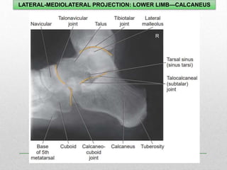
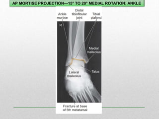
1. The document discusses various radiographic projections of the ankle, knee, and calcaneus including AP, lateral, oblique, and stress views.
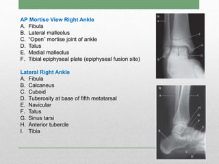
2. Standard positioning and techniques are outlined for visualizing specific anatomical structures like the ankle mortise, intercondylar fossa, and patellofemoral joint.
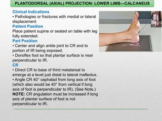
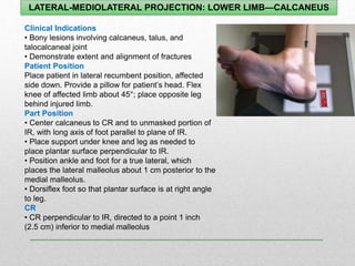
3. Projections using different patient positions are described, such as weight-bearing, prone, kneeling, and lateral recumbent to evaluate different conditions.