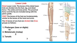
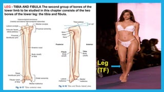
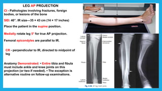
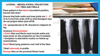
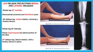
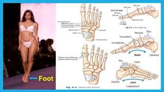
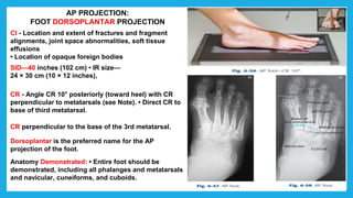
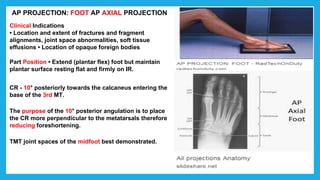
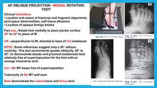
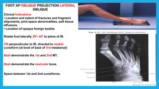
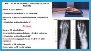
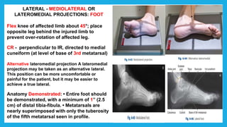
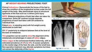
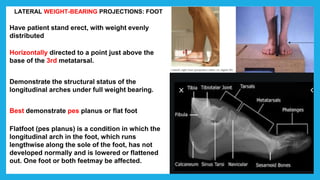
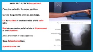
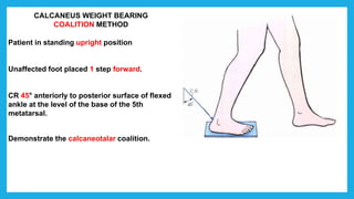
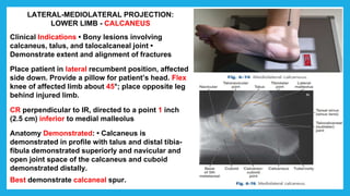
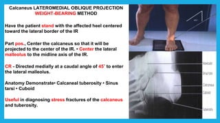
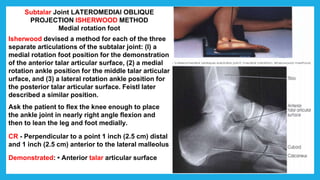
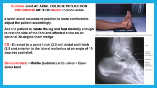
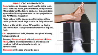
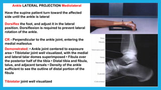
The document provides positioning and technical instructions for taking radiographs of various parts of the lower limb, including the foot, leg, toes, and calcaneus. It describes placing the patient in different positions such as supine, prone, lateral recumbent, and standing. It provides details on angling the central ray and image receptor to demonstrate specific anatomical structures like bones and joints. The instructions aim to clearly show fractures, dislocations, and other pathologies in different projections.
This document provides radiographic positioning guidelines for imaging the leg, knee, intercondylar fossa, and patella. It describes several projections for each area including AP, lateral, oblique, and weight-bearing views. For each projection, it specifies the image receptor size and position, patient position, positioning of the body part, and central ray direction. The document aims to provide standardized techniques to optimize image quality for evaluating various conditions.
This document provides guidelines for various radiographic projections of the shoulder, shoulder joint, acromioclavicular joint, and clavicle. It describes patient positioning, part positioning, image receptor size and orientation, central ray angle and direction, and clinical indications for 11 different shoulder projections, 9 shoulder joint projections, 4 acromioclavicular joint projections, and 6 clavicle projections. Precise positioning is emphasized to demonstrate relevant anatomy and identify injuries like fractures or dislocations.
This document provides an overview of ankle and foot radiography, including relevant anatomy, positioning techniques, and interpretations. It discusses key bones like the talus and calcaneus. Common projections are described for the ankle, including anteroposterior, lateral, mortise, and stress views. Foot projections include dorsiplantar, oblique, lateral, and weight-bearing. Positioning is outlined to properly visualize specific joints like the subtalar joint. Common pathologies and developmental variations are also mentioned.
This document provides information on various knee radiographic views including:
- AP, lateral, tunnel, oblique views of the knee joint
- Weight bearing AP view
- Patella PA, lateral, oblique axial views
- Various tangential views of the patella including sunrise, Hughston, Settegast, seated, Merchant, and Laurine views
It describes the patient positioning, part positioning, direction of the central ray, and evaluation criteria for each view to properly assess the knee anatomy and identify any abnormalities.
This document provides an overview of various pelvis x-ray projections, including their purposes, patient positioning, technical factors, and image evaluation criteria. It describes the anteroposterior (AP), inlet, outlet, Judet, and flamingo projections. The AP view examines the pelvic ring and bones. The inlet is perpendicular to the pelvic rim. The outlet assesses cephalad/caudal translation following trauma. The Judet views the acetabulum. And the flamingo series evaluates pubic symphysis instability with the patient in neutral, left foot raised, and right foot raised positions. Proper collimation, centering, orientation and other technical parameters are outlined for each view.
This document discusses various ankle x-ray views including:
- Anterior-posterior (AP) view which assesses the tibia, fibula, talus and metatarsals.
- Lateral view which assesses the tibia, fibula, talus, navicular, cuboid and calcaneum.
- Oblique views which rotate the foot internally or externally.
- Special views like the mortise view which assesses the tibial plafond and malleoli articulation with the talus, and stress views which evaluate ligament tears and joint stability. Patient positioning and technical factors are provided for each view.
This document provides an overview of various x-ray views of the wrist, hand, fingers, and thumb. It describes the positioning and anatomy visualized for common views like PA, lateral, and oblique views of the wrist, hand, and individual digits. It also summarizes views for assessing specific injuries like scaphoid fractures, carpal instability, and rheumatoid arthritis. Key views are highlighted for visualizing anatomy and fractures most clearly.
This document discusses special radiological views and techniques in orthopedics. It provides overviews of various projection views for imaging different parts of the body like the shoulder, elbow, wrist, hip, knee, ankle and spine. These include AP, PA, axial and oblique projections. It also summarizes applications of ultrasound and radioisotopic bone scanning in orthopedics, such as for detecting fractures, infections, tumors and assessing blood flow.
This document provides guidelines for obtaining radiographic images of the toes and foot. It describes different projection techniques, including AP, oblique, lateral, and tangential views. For each projection, it specifies the image receptor size, patient positioning, part positioning, and central ray direction. Projections are described for visualizing individual toes as well as the entire foot. Weight-bearing techniques are also outlined for evaluating the longitudinal arch of the foot.
The document describes the anatomy and radiographic projections of the elbow joint. It contains details on the bones that make up the elbow (humerus, radius, ulna), ligaments (radial collateral, ulnar collateral, annular), and motions (flexion, extension, pronation, supination). It also outlines the standard radiographic views of the elbow - anteroposterior, lateral, medial oblique, and tangential. Exposure factors and positioning for each view are provided, as well as normal radiographic findings.
This document provides guidelines for various radiographic projections of the pelvis, hip, acetabulum, and ilium. It describes patient positioning, part positioning, central ray direction, and image receptor placement for AP, lateral, oblique, and axial projections. Key projections include the AP pelvis, lateral hip, and oblique iliac crest views. Precise positioning is outlined to demonstrate anatomy and detect fractures or dislocations.
Radiographic positioning of humerus and shouldershajitha khan
The document describes various x-ray views of the humerus and shoulder. It discusses positioning, centering, and evaluation of anteroposterior, lateral, oblique, and axial views of the humerus. It also covers supine, upright, and stress views of the shoulder to evaluate fractures, dislocations, and other orthopedic injuries and conditions. Standard and specialized projections are outlined to demonstrate anatomy and identify abnormalities of the bones and joints.
Radiographic positioning of Upper limb (ELBOW & HUMERUS)Nasir Mohiudin
Radiographic Anatomy and Positioning of upper extremity, ELBOW & HUMERUS.
Indications, patient positioning, part positioning, Central beam direction, cassette size, collimating part, Tube distance. Buckey grid, exposure.
Special Radiographic views of elbow and humerus.
Images of radiographic positioning and radiographic film X rayed.
Exposure factors had been taken under the Machine used (Allengers 500 mA) under Digital radiography.
Anatomia y Posicionamiento de las extremidades superiores. Deseo aclarar que el video no me pertenece de ninguna manera. Se esta compartiendo publicamente con el fin de ayudar a los futuros tecnologos a obtener conocimiento para su revalida.
The document describes the anatomy and radiographic imaging of the shoulder. It discusses the bones, joints, ligaments, tendons, muscles, nerves, and blood vessels that make up the shoulder. It provides details on recommended radiographic projections to image the shoulder, including AP, axial, outlet, and glenohumeral joint views. Exposure factors, positioning, and evaluation criteria are outlined for each projection.
This document discusses the positioning, technique, and interpretation of cervical spine x-rays, including the anterior-posterior, lateral, odontoid, and oblique views. It outlines the proper positioning of the patient and equipment for each view to ensure accurate imaging of the cervical vertebrae and soft tissues. Key findings are described, such as equal disc heights and alignment of spinous processes and occipital condyles. The purpose of the different views and measurements taken are provided to evaluate the cervical spine for fractures, subluxations, and degenerative changes.
Presentation1.pptx thoraccic and lumber spineYashawant Yadav
The document provides an overview of radiographic techniques for imaging the thoracic and lumbar spine. It discusses the anatomy of the thoracic and lumbar spine and provides details on positioning, centering, and essential criteria for various projections including AP, lateral, and oblique views of both the thoracic and lumbar spine. The techniques are described for common indications like trauma, fractures, and degenerative conditions.
The document discusses various radiographic positioning techniques for imaging different anatomical areas and structures. It provides descriptions of positioning for paranasal sinus views, chest x-rays, spine views, shoulder views including scapula, wrist, hand, elbow, hip, knee and tibia/fibula views. For each area, it specifies the patient positioning, central ray direction, and structures that should be demonstrated in the resulting radiographic image.
The document provides instructions for positioning patients and obtaining x-ray images of the forearm and elbow. It describes how to perform anteroposterior and lateral projections of the forearm and elbow, including positioning the patient's arm and centering the x-ray beam. Proper positioning is needed to demonstrate anatomical structures like joints and bones on the x-ray image for diagnostic purposes.
1. The document discusses various radiographic projections of the ankle, knee, and calcaneus including AP, lateral, oblique, and stress views.
2. Standard positioning and techniques are outlined for visualizing specific anatomical structures like the ankle mortise, intercondylar fossa, and patellofemoral joint.
3. Projections using different patient positions are described, such as weight-bearing, prone, kneeling, and lateral recumbent to evaluate different conditions.
Beam hardening artifact occurs when an X-ray beam passes through multiple materials of varying densities within a scan volume. This causes the beam to become harder as lower energy photons are preferentially absorbed, leading to streaks or shading in the reconstructed CT image. Photon starvation is another cause of streak artifacts, occurring when there is insufficient photon flux passing through areas of higher attenuation, such as across the shoulders. Adaptive filtering and modulating tube current based on attenuation can help reduce these artifacts. Ring artifacts from defective detector elements in older CT scanners appear as rings in the reconstructed images.
A DEXA scan uses dual energy x-ray absorption to measure bone mineral density and assess osteoporosis risk. It involves passing two low-dose x-ray beams through the body to create a 2D image and calculate the density in specific areas like the spine or hip. DEXA is the most effective technique for measuring bone mineral density and uses T-scores and Z-scores to evaluate results against young adults and age-matched peers respectively.
The document provides an overview of knee joint anatomy and various x-ray views used to image the knee, including positioning, anatomy visualized, and clinical indications. It describes standard anterior-posterior, lateral, and specialized views. Pathologies discussed include osteoarthritis, osteochondroma, osteochondritis dissecans, fractures, and effusions. Images demonstrate normal anatomy and examples of fractures, loose bodies, and degenerative changes.
This document outlines the protocol for performing CT angiography (CTA) from the cerebral arteries to the lower limbs. It discusses indications for CTA including aneurysms, stenosis, dissections, and more. The preparation, positioning, and scanning protocols are provided for CTA of the head to lower limbs as well as the subclavian arteries. Pediatric protocols are also summarized. The document concludes with examples of CTA findings and references.
Advanced radiographic positions for the lower extremitiesmr_koky
Have patient sit on edge of chair with knee flexed 90° and foot flat on
floor. Place cassette under knee and have patient lean forward slightly to maintain
position.
Central Ray
Direct CR tangential to femoropatellar joint space (15° to 20° from lower leg).
Minimum SID is 40 inches (100 cm).
MDCT provides high resolution images through rapid acquisition of multiple slices during a single rotation. It uses multiple detector arrays rather than a single row, allowing acquisition of more data in less time. Image reconstruction involves back projection, iterative, or analytical methods to assign CT numbers based on x-ray attenuation. Applications include angiography, cardiac imaging, and virtual endoscopy due to improved temporal and spatial resolution compared to earlier CT technologies.
This document provides information on various radiographic views of the shoulder joint, including positioning, technical details, and radiographic anatomy seen in each view. It describes the standard anteroposterior, axial, and reverse axial views as well as special projections like the Garth, Wallace, Y, West Point, Stryker, and Grashey views. Each projection is outlined with details on how to position the patient and technical exposure factors to demonstrate specific shoulder anatomy and pathologies.
1. The document discusses various radiographic projections of the ankle, knee, and calcaneus including AP, lateral, oblique, and stress views.
2. Standard positioning and techniques are outlined for visualizing specific anatomical structures like the ankle mortise, intercondylar fossa, and patellofemoral joint.
3. Projections using different patient positions are described, such as weight-bearing, prone, kneeling, and lateral recumbent to evaluate different conditions.
This document provides guidance on taking and interpreting foot x-rays. It discusses the standard views taken - AP, lateral, and oblique. It describes how to evaluate bones, cartilage, and joints of the foot seen on each view, including the talus, calcaneus, navicular, cuboid, cuneiforms, and metatarsals. Common fractures like Jones fractures of the 5th metatarsal and Lisfranc injuries are explained. Interpretation of the calcaneal-cuboid angle and Lisfranc ligament integrity are important. Neuropathic conditions like Charcot foot and midfoot injuries such as Chopart fractures are also briefly covered.
This document provides an overview of knee x-ray and MRI examinations. It describes the normal anatomy seen on x-rays and MRI, various imaging projections used for the knee, and common pathologies that can be identified. Key indications for knee x-rays are listed as trauma, suspected osteoarthritis, infection, and to evaluate for fractures or joint effusions. Common fractures discussed include tibial plateau fractures and patellar fractures. The document also provides details on measurements taken from knee x-rays.
This document discusses anterior knee pain and the patellofemoral joint. It covers the anatomy and biomechanics of the patellofemoral joint. Various imaging methods for assessing the patellofemoral joint are described, including their limitations. A differential diagnosis of anterior knee pain conditions is provided, along with descriptions of pathologies like patellofemoral pain syndrome, lateral patellar dislocation, and osteochondritis dissecans.
MRI is commonly used to evaluate the knee joint. The document outlines the standard MRI protocol for the knee, including patient positioning, coil selection, routine sequences, and advanced applications. Parameters such as slice thickness, FOV, and pulse sequences are discussed to optimize visualization of structures like ligaments, cartilage, and menisci.
This document discusses clubfoot (CTEV), including:
1. The historical aspects and development of treatment methods over time, from Hippocrates to modern techniques.
2. The anatomy, components, and classification of clubfoot deformities.
3. Treatment methods including the Ponseti method of serial casting and bracing, which has a 95% success rate when compliant.
4. Surgical indications and techniques for resistant or relapsed cases.
The key points covered are the evolution of clubfoot treatment, the Ponseti method as the gold standard non-surgical approach,
Ankle injuries are common and can result from sports injuries, falls, or accidents. The ankle is a synovial hinge joint formed by the tibia, fibula, and talus bone. It is stabilized by ligaments including the deltoid ligament medially and lateral ligaments laterally. Common ankle injuries include sprains of the lateral ligaments from inversion forces. Sprains are graded based on the severity of ligament tearing. Treatment involves RICE (rest, ice, compression, elevation) and rehabilitation. More severe injuries may require surgery to repair torn ligaments. Radiographs can identify fractures but stress views are sometimes needed to diagnose ligament injuries.
This document discusses congenital vertical talus (CVT), a rare foot deformity. It begins by defining CVT and providing background information. It then describes the anatomy and pathoanatomy of CVT. Key points include that CVT results in an almost vertical talus bone and rigid flatfoot deformity. Treatment involves serial casting and manipulation to prepare for surgery, with the goal of restoring normal anatomical relationships in the foot. Surgical techniques described include open reduction and percutaneous fixation of the talonavicular joint with K-wires. Complications of surgery can include wound issues and stiffness.
Presentation1.pptx. ultrasound examination of the ankle joint.Abdellah Nazeer
This document provides an ultrasound protocol for examining the ankle joint, including descriptions of normal anatomy and potential abnormalities. It discusses scanning techniques for the lateral, anterior, medial, and posterior aspects of the ankle. Common tendon injuries and conditions such as tenosynovitis, tendinosis, ruptures, and bursitis are described. The roles of ultrasound in ankle examination and its limitations are also noted. Key structures like the peroneal and posterior tibial tendons are highlighted.
Club foot, or congenital talipes equinus varus, is a complex three-dimensional deformity of the foot with four main components: equinus, varus, adductus, and cavus. It has an incidence of about 1 in 1,000 live births. Treatment involves serial manipulation and casting, most commonly using the Ponseti method, with the goal of correcting all deformity components to achieve a functional, plantigrade foot. Maintenance treatment with a foot abduction brace is also required to prevent recurrence of the deformity. Surgery may be needed for resistant, relapsed, or neglected clubfoot cases and involves soft tissue releases to address all pathological structures.
This document provides an overview of clubfoot (CTEV), including:
1. The historical aspects and key figures in the development of clubfoot treatment methods.
2. The anatomy and biomechanics involved in clubfoot deformity.
3. The Ponseti method of non-surgical clubfoot correction, which involves weekly manipulation, casting, and often a percutaneous Achilles tenotomy.
4. Important considerations for casting including proper manipulation technique and ensuring adequate foot abduction prior to tenotomy.
5. Potential complications of casting and the process of cast removal.
Dres. Héctor Domínguez Hernández y Victor Hugo Cruz
Residentes de Imagenología
Dan Inicio al módulo de musculoesquelético.
Anatomía básica de tobillo por ultrasonido.
Congenital talipes equinovarus, or clubfoot, is a birth defect affecting the foot and ankle. It occurs in approximately 1 in 1000 live births. The deformity involves equinus (plantar flexion) of the ankle, varus and inversion of the heel, and adduction and supination of the forefoot. Non-surgical treatment involves serial casting and manipulation based on the Ponseti method. This involves weekly cast changes to gradually correct the deformity, often including a percutaneous Achilles tenotomy. Surgical treatment is reserved for resistant cases and involves soft tissue releases and occasionally bony procedures. Proper bracing after correction is critical to prevent relapse of the deformity. With appropriate treatment
The document discusses considerations for total knee arthroplasty (TKA). It covers:
1) The history and goals of TKA, along with evolving implant designs.
2) The importance of thorough knowledge of knee anatomy and achieving proper soft tissue balancing during surgery.
3) Key steps of TKA including bone cuts, gap balancing, patella tracking, cementing and ensuring proper flexion and extension.
Radiographic views of proximal femur and pelvisChandan Prasad
This document provides information on radiographic views of the proximal femur and pelvis, including:
1) It lists several clinical indications for which these views would be used, such as fractures, degenerative diseases, and bone lesions.
2) It describes the positioning and technical factors for several common views, including AP pelvis, AP bilateral frog-leg, AP axial outlet, and posterior oblique pelvis-acetabulum views.
3) For each view, it provides details on patient and part positioning, central ray angle and direction, and clinical indications for use.
This document provides an overview of ankle radiography including:
- The Ottawa Ankle Rules for determining when radiographs are needed
- Common radiographic projections of the ankle including AP, mortise, and lateral views
- Measurements taken from the different views to assess for fractures and ligament injuries
- Stress tests that can be performed under fluoroscopy to evaluate ligament integrity
- Classification systems for common ankle fractures like the Danis-Weber and Pott's classifications
This document provides information on radiographic techniques for imaging the upper limb, including the hand, wrist, forearm, elbow, and arm. It describes patient positioning and central ray direction for various projections of each area. Standard projections covered include PA, lateral, and oblique views of the fingers, thumb, hand, and wrist. Specialized projections are also outlined, such as the modified Robert's method for the thumb and Folio stress test for ulnar collateral ligament injuries. Evaluation criteria emphasize proper anatomy demonstration and avoidance of rotation for each view.
RADIOGRAPHIC TECHNIQUE OF UPPER LIMB BY SAGAR CHAULAGAINSagar Chaulagain
Calling all aspiring radiography professionals! Dive into the intricate world of upper limb radiography with this comprehensive guide tailored to meet the technical demands of radiography field students. From mastering essential techniques to understanding complex pathologies, this presentation equips you with the knowledge and skills necessary to excel in the radiology field.
Here's what you'll discover:
Radiographic Techniques Demystified: Unlock the secrets of acquiring clear and precise radiographic images of the upper limb. Explore a variety of positioning techniques, exposure factors, and tube-object distances to capture optimal views for diagnostic assessment.
Indications and Pathologies: Gain insight into the clinical indications and common pathologies encountered in upper limb radiography. From fractures and dislocations to degenerative joint diseases, learn to identify and interpret radiographic findings with confidence.
Radiation Protection and Safety Protocols: Prioritize patient and staff safety with rigorous adherence to radiation protection measures. Explore best practices for minimizing radiation exposure, including shielding techniques, collimation, and dose optimization strategies.
Image Characteristics and Evaluation Criteria: Develop a keen eye for assessing radiographic images of the upper limb. Understand the key characteristics and evaluation criteria essential for accurate interpretation and diagnosis.
Basic and Supplementary Views: Master the art of acquiring basic views while understanding the necessity and technique behind supplementary views. Explore the role of oblique, tangential, and special projections in revealing hidden pathologies and anatomical details.
Exposure Factors and Optimization: Delve into exposure factors and their impact on image quality and radiation dose. Learn how to manipulate exposure parameters effectively to achieve optimal results while minimizing patient exposure.
Designed as a comprehensive resource for radiography students, this presentation serves as a roadmap to navigate the complexities of upper limb radiography. Whether you're honing your skills in the classroom or preparing for clinical practice, this guide offers invaluable insights to elevate your proficiency and confidence in the radiology field.
Deep Behavioral Phenotyping in Systems Neuroscience for Functional Atlasing a...Ana Luísa Pinho
Functional Magnetic Resonance Imaging (fMRI) provides means to characterize brain activations in response to behavior. However, cognitive neuroscience has been limited to group-level effects referring to the performance of specific tasks. To obtain the functional profile of elementary cognitive mechanisms, the combination of brain responses to many tasks is required. Yet, to date, both structural atlases and parcellation-based activations do not fully account for cognitive function and still present several limitations. Further, they do not adapt overall to individual characteristics. In this talk, I will give an account of deep-behavioral phenotyping strategies, namely data-driven methods in large task-fMRI datasets, to optimize functional brain-data collection and improve inference of effects-of-interest related to mental processes. Key to this approach is the employment of fast multi-functional paradigms rich on features that can be well parametrized and, consequently, facilitate the creation of psycho-physiological constructs to be modelled with imaging data. Particular emphasis will be given to music stimuli when studying high-order cognitive mechanisms, due to their ecological nature and quality to enable complex behavior compounded by discrete entities. I will also discuss how deep-behavioral phenotyping and individualized models applied to neuroimaging data can better account for the subject-specific organization of domain-general cognitive systems in the human brain. Finally, the accumulation of functional brain signatures brings the possibility to clarify relationships among tasks and create a univocal link between brain systems and mental functions through: (1) the development of ontologies proposing an organization of cognitive processes; and (2) brain-network taxonomies describing functional specialization. To this end, tools to improve commensurability in cognitive science are necessary, such as public repositories, ontology-based platforms and automated meta-analysis tools. I will thus discuss some brain-atlasing resources currently under development, and their applicability in cognitive as well as clinical neuroscience.
EWOCS-I: The catalog of X-ray sources in Westerlund 1 from the Extended Weste...Sérgio Sacani
Context. With a mass exceeding several 104 M⊙ and a rich and dense population of massive stars, supermassive young star clusters
represent the most massive star-forming environment that is dominated by the feedback from massive stars and gravitational interactions
among stars.
Aims. In this paper we present the Extended Westerlund 1 and 2 Open Clusters Survey (EWOCS) project, which aims to investigate
the influence of the starburst environment on the formation of stars and planets, and on the evolution of both low and high mass stars.
The primary targets of this project are Westerlund 1 and 2, the closest supermassive star clusters to the Sun.
Methods. The project is based primarily on recent observations conducted with the Chandra and JWST observatories. Specifically,
the Chandra survey of Westerlund 1 consists of 36 new ACIS-I observations, nearly co-pointed, for a total exposure time of 1 Msec.
Additionally, we included 8 archival Chandra/ACIS-S observations. This paper presents the resulting catalog of X-ray sources within
and around Westerlund 1. Sources were detected by combining various existing methods, and photon extraction and source validation
were carried out using the ACIS-Extract software.
Results. The EWOCS X-ray catalog comprises 5963 validated sources out of the 9420 initially provided to ACIS-Extract, reaching a
photon flux threshold of approximately 2 × 10⁻⁸ photons cm−2
s
−1
. The X-ray sources exhibit a highly concentrated spatial distribution,
with 1075 sources located within the central 1 arcmin. We have successfully detected X-ray emissions from 126 out of the 166 known
massive stars of the cluster, and we have collected over 71 000 photons from the magnetar CXO J164710.20-455217.
ESR spectroscopy in liquid food and beverages.pptxPRIYANKA PATEL
With increasing population, people need to rely on packaged food stuffs. Packaging of food materials requires the preservation of food. There are various methods for the treatment of food to preserve them and irradiation treatment of food is one of them. It is the most common and the most harmless method for the food preservation as it does not alter the necessary micronutrients of food materials. Although irradiated food doesn’t cause any harm to the human health but still the quality assessment of food is required to provide consumers with necessary information about the food. ESR spectroscopy is the most sophisticated way to investigate the quality of the food and the free radicals induced during the processing of the food. ESR spin trapping technique is useful for the detection of highly unstable radicals in the food. The antioxidant capability of liquid food and beverages in mainly performed by spin trapping technique.
ESPP presentation to EU Waste Water Network, 4th June 2024 “EU policies driving nutrient removal and recycling
and the revised UWWTD (Urban Waste Water Treatment Directive)”
Unlocking the mysteries of reproduction: Exploring fecundity and gonadosomati...AbdullaAlAsif1
The pygmy halfbeak Dermogenys colletei, is known for its viviparous nature, this presents an intriguing case of relatively low fecundity, raising questions about potential compensatory reproductive strategies employed by this species. Our study delves into the examination of fecundity and the Gonadosomatic Index (GSI) in the Pygmy Halfbeak, D. colletei (Meisner, 2001), an intriguing viviparous fish indigenous to Sarawak, Borneo. We hypothesize that the Pygmy halfbeak, D. colletei, may exhibit unique reproductive adaptations to offset its low fecundity, thus enhancing its survival and fitness. To address this, we conducted a comprehensive study utilizing 28 mature female specimens of D. colletei, carefully measuring fecundity and GSI to shed light on the reproductive adaptations of this species. Our findings reveal that D. colletei indeed exhibits low fecundity, with a mean of 16.76 ± 2.01, and a mean GSI of 12.83 ± 1.27, providing crucial insights into the reproductive mechanisms at play in this species. These results underscore the existence of unique reproductive strategies in D. colletei, enabling its adaptation and persistence in Borneo's diverse aquatic ecosystems, and call for further ecological research to elucidate these mechanisms. This study lends to a better understanding of viviparous fish in Borneo and contributes to the broader field of aquatic ecology, enhancing our knowledge of species adaptations to unique ecological challenges.
The use of Nauplii and metanauplii artemia in aquaculture (brine shrimp).pptxMAGOTI ERNEST
Although Artemia has been known to man for centuries, its use as a food for the culture of larval organisms apparently began only in the 1930s, when several investigators found that it made an excellent food for newly hatched fish larvae (Litvinenko et al., 2023). As aquaculture developed in the 1960s and ‘70s, the use of Artemia also became more widespread, due both to its convenience and to its nutritional value for larval organisms (Arenas-Pardo et al., 2024). The fact that Artemia dormant cysts can be stored for long periods in cans, and then used as an off-the-shelf food requiring only 24 h of incubation makes them the most convenient, least labor-intensive, live food available for aquaculture (Sorgeloos & Roubach, 2021). The nutritional value of Artemia, especially for marine organisms, is not constant, but varies both geographically and temporally. During the last decade, however, both the causes of Artemia nutritional variability and methods to improve poorquality Artemia have been identified (Loufi et al., 2024).
Brine shrimp (Artemia spp.) are used in marine aquaculture worldwide. Annually, more than 2,000 metric tons of dry cysts are used for cultivation of fish, crustacean, and shellfish larva. Brine shrimp are important to aquaculture because newly hatched brine shrimp nauplii (larvae) provide a food source for many fish fry (Mozanzadeh et al., 2021). Culture and harvesting of brine shrimp eggs represents another aspect of the aquaculture industry. Nauplii and metanauplii of Artemia, commonly known as brine shrimp, play a crucial role in aquaculture due to their nutritional value and suitability as live feed for many aquatic species, particularly in larval stages (Sorgeloos & Roubach, 2021).
What is greenhouse gasses and how many gasses are there to affect the Earth.moosaasad1975
What are greenhouse gasses how they affect the earth and its environment what is the future of the environment and earth how the weather and the climate effects.
ANAMOLOUS SECONDARY GROWTH IN DICOT ROOTS.pptxRASHMI M G
Abnormal or anomalous secondary growth in plants. It defines secondary growth as an increase in plant girth due to vascular cambium or cork cambium. Anomalous secondary growth does not follow the normal pattern of a single vascular cambium producing xylem internally and phloem externally.
The binding of cosmological structures by massless topological defectsSérgio Sacani
Assuming spherical symmetry and weak field, it is shown that if one solves the Poisson equation or the Einstein field
equations sourced by a topological defect, i.e. a singularity of a very specific form, the result is a localized gravitational
field capable of driving flat rotation (i.e. Keplerian circular orbits at a constant speed for all radii) of test masses on a thin
spherical shell without any underlying mass. Moreover, a large-scale structure which exploits this solution by assembling
concentrically a number of such topological defects can establish a flat stellar or galactic rotation curve, and can also deflect
light in the same manner as an equipotential (isothermal) sphere. Thus, the need for dark matter or modified gravity theory is
mitigated, at least in part.
2. Lower Limb
Distal Lower Limb. The bones of the distal lower
limb are divided into the foot, leg, and distal
femur. The ankle and knee joints. The proximal
femur and the hip are included along with the
pelvic girdle.
FOOT The bones of the foot are fundamentally
similar to the bones of the hand and wrist,
The 26 bones of one foot are divided into three
groups as follows:
1. Phalanges (toes or digits)
14
2. Metatarsals (instep)
5
3. Tarsals
7
3. Leg
(TF)
LEG - TIBIA AND FIBULA The second group of bones of the
lower limb to be studied in this chapter consists of the two
bones of the lower leg: the tibia and fibula.
4. LEG AP PROJECTION
CI - Pathologies involving fractures, foreign
bodies, or lesions of the bone
SID: 40”. IR size—35 × 43 cm (14 × 17 inches)
Place the patient in the supine position.
Medially rotate leg 5° for true AP projection.
Femoral epicondyles are parallel to IR.
CR - perpendicular to IR, directed to midpoint of
leg
Anatomy Demonstrated: • Entire tibia and fibula
must include ankle and knee joints on this
projection (or two if needed). • The exception is
alternative routine on follow-up examinations.
5. LATERAL - MEDIOLATERAL PROJECTION:
LEG TIBIA AND FIBULA
Place patient in the lateral recumbent position,
injured side down
Ensure that both ankle and knee joints are 1 – 2”
(3 to 5 cm) from ends of IR so that divergent rays
do not project either joint off IR.
CR - perpendicular to IR, directed to midpoint of
leg
Anatomy Demonstrated:
• Entire tibia and fibula must include ankle and
knee joints on this projection (or two if needed).
• Exception is alternative routine on follow-up
examinations.
Distal fibula lying posterior over half of the tibia.
Tibial tuberosity in profile
Overlap tibia on the proximal fibular head.
6. LEG OBLIQUE PROJECTIONS MEDIAL
AND LATERAL OBLIQUES
Rotate leg 45° medially.
Demonstrate proximal and tibiofibular joint.
AP oblique leg. medial rotation. showing a
fixation device.
Rotate leg 45° laterally.
Fibula superimposed by lateral portion of
the tibia.
AP oblique leg. lateral rotation. with a
fixation device in place.
9. AP / AP Axial PROJECTION: TOES
CI • Fractures or dislocations of the phalanges of the
digits in question • Pathologies such as
osteoarthritis and gouty arthritis (gout), especially in
the first digit
SID - 40 inches (102 cm) • IR size - 18 × 24 cm (8 × 10
inches)
Part pos., Center and align long axis of digit to CR
and long axis of portion of IR being exposed. •
Ensure that MTP joint of digit in question is centered
to CR.
AP PROJECTION • CR perpendicular to 3rd MTP (if
15° wedge is placed under foot).
AP AXIAL PROJECTION •
CR 10°-15° posteriorly to 3rd MTP (to open-up joint
space)
Anatomy Demonstrated: • Digits of interest and a
minimum of the distal half of metatarsals should be
included.
10. TOES PA PROJECTION
Patient prone on the x-ray table with the
dorsal aspect in contact with the IR.
CR - perpendicular to 3rd MTP joint.
Well demonstrated IP joint spaces because
the natural divergence of the x-ray beam
coincides closely with the position of the
toes.
11. AP OBLIQUE PROJECTION - MEDIAL OR
LATERAL ROTATION: TOES
CI • Fractures or dislocations of the phalanges of
the digits in question • Pathologies such as
osteoarthritis and gouty arthritis (gout), especially
in the first digit
Medially rotate leg 30°-45° from the plane of the IR.
For 1st, 2nd and 3rd digit
Laterally rotate leg 30°-45° from the plane of the IR
For 4th and 5th digit.
CR - perpendicular to 3rd MTP joint
Anatomy Demonstrated: • Digits in question and
distal half of metatarsals should be included without
overlap (superimposition).
Routine position of the foot that gives a different
perspective than that of the AP.
12. LATERAL - MEDIOLATERAL OR
LATEROMEDIAL PROJECTIONS: TOES
Patient in lateral recumbent position.Rotate affected
leg and foot medially (lateromedial) for first, second,
and third digits and laterally (mediolateral) for fourth
and fifth digits.
1ST - 2nd digit
• Lateral recumbent on unaffected side.
2nd - 5th digit
• Lateral recumbent on affected side.
CR - perpendicular to PIP joint
Anatomy Demonstrated: • Phalanges of digit in
question should be seen in lateral position free of
superimposition by other digits, if possible. • (When
total separation of toes is impossible, especially
third to fifth digits, the distal phalanx at least should
be separated, and the proximal phalanx should be
visualized through superimposed structures.)
13. TANGENTIAL PROJECTION: TOES –
SESAMOIDS LEWIS METHOD
CI - This projection provides a profile image of the
sesamoid bones at the first MTP joint for evaluation of
extent of injury
Patient in prone position
Dorsiflex the foot so that plantar surface of foot forms
about 15°-20° angle from vertical
CR - perpendicular and tangential to the 1st MTP joint.
Demonstrate possible fracture of the sesamoid bone.
Uncomfortable and often painful position for the
demonstration of the sesamoid bone.
14. TANGENTIAL PROJECTION: TOES—
SESAMOIDS HOLLY METHOD
Patient in supine/sitting position.
Plantar surface form an angle of 75° with plane of film.
CR- perpendicular to the head of the 1st metatarsal
bone
Sesamoid bone in profile
• A position that is more comfortable for the patient as
compared with Lewis method.
CR perpendicular to IR, directed tangentially to
posterior aspect of first MTP joint (depending on
amount of dorsiflexion of foot, may need to angle CR
slightly for a true tangential projection)
Demonstrate possible fracture of the sesamoid bone.
15. SESAMOID BONE CAUSTON METHOD
Patient in lateral recumbent position.
Directed to the prominence of the 1st MTP joint at
an angle of 40° toward the heel.
Sesamoid bone projected axiolaterally with a slight
overlap.
16. AP PROJECTION:
FOOT DORSOPLANTAR PROJECTION
CI - Location and extent of fractures and fragment
alignments, joint space abnormalities, soft tissue
effusions
• Location of opaque foreign bodies
SID—40 inches (102 cm) • IR size—
24 × 30 cm (10 × 12 inches),
CR - Angle CR 10° posteriorly (toward heel) with CR
perpendicular to metatarsals (see Note). • Direct CR to
base of third metatarsal.
CR perpendicular to the base of the 3rd metatarsal.
Dorsoplantar is the preferred name for the AP
projection of the foot.
Anatomy Demonstrated: • Entire foot should be
demonstrated, including all phalanges and metatarsals
and navicular, cuneiforms, and cuboids.
17. AP PROJECTION: FOOT AP AXIAL PROJECTION
Clinical Indications
• Location and extent of fractures and fragment
alignments, joint space abnormalities, soft tissue
effusions • Location of opaque foreign bodies
Part Position • Extend (plantar flex) foot but maintain
plantar surface resting flat and firmly on IR.
CR - 10° posteriorly towards the calcaneus entering the
base of the 3rd MT.
The purpose of the 10° posterior angulation is to place
the CR more perpendicular to the metatarsals therefore
reducing foreshortening.
TMT joint spaces of the midfoot best demonstrated.
18. AP OBLIQUE PROJECTION - MEDIAL ROTATION:
FOOT
Clinical Indications
• Location and extent of fractures and fragment alignments,
joint space abnormalities, soft tissue effusions
• Location of opaque foreign bodies
Part pos., Rotate foot medially to place plantar surface
30° to 40° to plane of IR
CR - perpendicular to IR, directed to base of 3rd metatarsal
NOTE: Some references suggest only a 30° oblique
routinely. This text recommends greater obliquity, 40° to
45°, to demonstrate tarsals and proximal metatarsals best
relatively free of superimposition for the foot with an
average transverse arch.
3rd - 5th MT bases free of superimposition
Tuberosity of 5th MT well seen
Best demonstrate the cuboid bone and Sinus tarsi
19. FOOT AP OBLIQUE PROJECTION LATERAL
OBLIQUE
Clinical Indications
• Location and extent of fractures and fragment
alignments, joint space abnormalities, soft tissue
effusions
• Location of opaque foreign bodies
Rotate foot laterally 30°- 45° to plane of IR.
CR perpendicular to IR, directed to medial
cuneiform (at level of base of 3rd metatarsal)
Best demonstrate the 1st and 2nd MT.
Best demonstrate the navicular bone.
Space between 1st and 2nd cuneiforms.
20. FOOT PA PLANTODORSAL OBLIQUE GRASHEY
METHOD
Patient in prone position
CR perpendicular to base of 3rd metatarsal.
Alternative projection for medial or lateral oblique of the
foot.
1. Rotate foot and heel medially 30°
Navicular
Same as AP lateral oblique
demonstrate interspaces between 1st & 2nd metatarsal
2. Rotate foot and heel laterally 20°
Demonstrate interspaces between 2nd, 3rd, 4th & 5th
metatarsal
Tuberosity of 5th metatarsal
Cuboid same as AP medial oblique
21. LATERAL - MEDIOLATERAL OR
LATEROMEDIAL PROJECTIONS: FOOT
Flex knee of affected limb about 45°; place
opposite leg behind the injured limb to
prevent over-rotation of affected leg.
CR - perpendicular to IR, directed to medial
cuneiform (at level of base of 3rd metatarsal)
Alternative lateromedial projection A lateromedial
projection may be taken as an alternative lateral.
This position can be more uncomfortable or
painful for the patient, but it may be easier to
achieve a true lateral.
Anatomy Demonstrated: • Entire foot should
be demonstrated, with a minimum of 1” (2.5
cm) of distal tibia-fibula. • Metatarsals are
nearly superimposed with only the tuberosity
of the fifth metatarsal seen in profile.
22. AP WEIGHT-BEARING PROJECTIONS: FOOT
Clinical Indications • Demonstrate the bones of the feet to
show the condition of the longitudinal arches under the full
weight of the body • May demonstrate injury to structural
ligaments of the foot such as a Lisfranc joint injury
NOTE: Bilateral projections of both feet often are taken for
comparison. Some AP routines include separate
projections of each foot taken with CR centered to
individual foot.
Patient pos,. in standing erect with full weight evenly
distributed on both feet
CR 15° posteriorly to midpoint between feet at the level of
the base of metatarsal.
This projection can be used to show the alignment of the
metatarsals and phalanges in cases of hallux valgus.
Hallux valgus is the commonest forefoot deformity, with an
estimated prevalence of 23% to 35%. It causes symptoms
on the medial edge of the foot, the sole, and the small toes.
Non-operative treatment may alleviate symptoms but does
not correct the deformity of the big toe
23. LATERAL WEIGHT-BEARING PROJECTIONS: FOOT
Have patient stand erect, with weight evenly
distributed
Horizontally directed to a point just above the
base of the 3rd metatarsal.
Demonstrate the structural status of the
longitudinal arches under full weight bearing.
Best demonstrate pes planus or flat foot
Flatfoot (pes planus) is a condition in which the
longitudinal arch in the foot, which runs
lengthwise along the sole of the foot, has not
developed normally and is lowered or flattened
out. One foot or both feetmay be affected.
24. AP AXIAL PROJECTION WEIGHT-BEARING
COMPOSITE METHOD Standing
SID: 40” IR: 24 x 30 cm lengthwise
Patient standing upright, adjust the IR under the
foot and center its midline to the long axis of the
foot
CR - Frontal projection of all bones of the foot
using the masking effect of the leg. With the tube
in front of the patient and adjusted for a
posterior angulation of 15˚, center the central ray
to the base of the third metatarsal for the first
exposure
AD - The following should be clearly
demonstrated: • All tarsals
• Shadow of leg not overlapping the tarsals •
Foot not rotated • Tarsal , metatarsals, and toe
with similar densities
25. Congenital Clubfoot AP PROJECTION
KITE METHODS
The typical clubfoot, called talipes equinovarus, hows
three deviations from the normal alignment of the foot in
relation to the weight-bearing axis of the leg.
The classic Kite methods - exactly placed AP and lateral
projections for radiography of the clubfoot are used to
demonstrate the anatomy of the foot and the bone or
ossification centers of the tarsal and their relation to one
another. Ossificstion means the natural process of bone
formation
Place the infant in the supine position, with the hip and
knees flexed to permit the foot to rest flat on the fR.
Elevate the body on firm pil lows to knee height to
simplify both gonad shielding and leg adjustment.
CR perpendicular midway between the tarsals (Bilateral).
15° posteriorly (CR perpendicular to tarsal area).
(15°) True relationship and ossification centers of the
tarsals.
Demonstrate the degree of inversion of the calcaneus.
Demonstrate the degree of adduction of the forefoot.
26. Congenital Clubfoot AXIAL PROJECTION
Dorsoplantar KANDEL METHOD
For this method the infant is held in a vertical or a
bending-forward position.
CR - 40° anteriorly through the lower leg.
Démontrâtes sustentaculum talar joint fusion.
Recommended dorsoplantar axial projection of the
patient with clubfoot.
27. PLANTODORSAL (AXIAL) PROJECTION:
LOWER LIMB - CALCANEUS
Clinical Indications • Pathologies or fractures with
medial or lateral displacement
PX pos., Supine/sitting
Direct CR to base of 3rd metatarsal to emerge at a
level just distal to lateral malleolus.
Angle CR 40° cephalad from long axis of foot (which
also would be 40° from vertical if long axis of foot is
perpendicular to IR
Best demonstrate medial or lateral displacement of
the calcaneus.
Open Talocalcaneal joint
Sustentaculum tali
28. AXIAL PROJECTION Dorsoplantar
Place the patient in the prone position.
Elevate the patient's ankle on sandbags.
CR 40° caudad to dorsal surface of the ankle
joint.
Best demonstrate medial or lateral displacement
of the calcaneus.
Axial projection of the calcaneus
Open Talocalcaneal joint
Sustentaculum tali
29. CALCANEUS WEIGHT BEARING
COALITION METHOD
Patient in standing upright position
Unaffected foot placed 1 step forward.
CR 45° anteriorly to posterior surface of flexed
ankle at the level of the base of the 5th
metatarsal.
Demonstrate the calcaneotalar coalition.
30. LATERAL-MEDIOLATERAL PROJECTION:
LOWER LIMB - CALCANEUS
Clinical Indications • Bony lesions involving
calcaneus, talus, and talocalcaneal joint •
Demonstrate extent and alignment of fractures
Place patient in lateral recumbent position, affected
side down. Provide a pillow for patient’s head. Flex
knee of affected limb about 45°; place opposite leg
behind injured limb.
CR perpendicular to IR, directed to a point 1 inch
(2.5 cm) inferior to medial malleolus
Anatomy Demonstrated: • Calcaneus is
demonstrated in profile with talus and distal tibia-
fibula demonstrated superiorly and navicular and
open joint space of the calcaneus and cuboid
demonstrated distally.
Best demonstrate calcaneal spur.
31. Calcaneus LATEROMEDIAL OBLIQUE PROJECTION
WEIGHT-BEARING METHOD
Have the patient stand with the affected heel centered
toward the lateral border of the IR
Part pos., Center the calcaneus so that it will be
projected to the center of the IR. • Center the lateral
malleolus to the midline axis of the IR.
CR - Directed medially at a caudal angle of 45˚ to enter
the lateral malleolus.
Anatomy Demonstrate• Calcaneal tuberosity • Sinus
tarsi • Cuboid
Useful in diagnosing stress fractures of the calcaneus
and tuberosity.
32. Subtalar Joint PA AXIAL OBLIQUE
PROJECTION Lateral rotation
Have the patient lie on the affected side in the
lateral position.
Ask the patient to extend the affected limb. •
Roll the Limb lightly forward from the lateral
position.
CR - Directed to the ankle joint at a double angIe
of 5˚ anterior and 23˚ caudal.
The following should be clearly demonstrated: •
Open subtalar (talocalcaneal) joint articulations
• Sinus tarsi • Lateral malleolus seen in profile
33. Subtalar Joint AP AXIAL OBLIQUE PROJECTION
BRODEN METHOD! Medial Rotation
Broden! recommended the lateromedial and
mediolateral right-angle oblique projection for
demonstration of the posterior articular facet of the
calcaneus to determine the presence of joint
involvement in cases of comminuted fracture.
Place the patient in the supine position. o Adjust a
small sandbag under each knee.
Adjust the IR so that the lower edge is about 1 inch
(2.5 cm) distal to the plantar surface of the heel
CR - Angled cephalad at 40, 30, 20, and 10˚,
respectively. Four separate images are obtained
For each image, direct the central ray to a point 2 or
3 cm caudoanteriorly to the lateral malleolus, to the
midpoint of an imaginary line
Demonstrated: • Anterior and posterior portions of
the posterior subtalar joint
34.
35. Subtalar Joint AP AXIAL OBLIQUE PROJECTION
BRODEN METHOD Lateral rotation
Place the patient in the supine position. • Adjust a
small sandbag under each knee.
With the patient's ankle joint held in right-angle
flexion, rotate the leg and foot 45˚ laterally
Directed to a point 2 cm distal and 2 cm anterior to
the medial malleolus, at a cephalic angle of 15
degrees for the first exposure • Two or three images
may be made with a 3- or 4-degree difference in
central ray angulation
Demonstrated: • Posterior portion of the subtalar
joint
36. Subtalar Joint LATEROMEDIAl OBLIQUE
PROJECTION ISHERWOOD METHOD
Medial rotation foot
Isherwood devised a method for each of the three
separate articulations of the subtalar joint: (I) a
medial rotation foot position for the demonstration
of the anterior talar articular surface, (2) a medial
rotation ankle position for the middle talar articular
urface, and (3) a lateral rotation ankle position for
the posterior talar articular surface. Feistl later
described a similar position.
Ask the patient to flex the knee enough to place
the ankle joint in nearly right angle flexion and
then to lean the leg and foot medially.
CR - Perpendicular to a point 1 inch (2.5 cm) distal
and 1 inch (2.5 cm) anterior to the lateral malleolus
Demonstrated: • Anterior talar articular surface
37. Subtalar Joint AP AXIAL OBLIQUE PROJECTION
ISHERWOOD METHOD Medial rotation ankle
a semi lateral recumbent position is more comfortable,
adjust the patient accordingly.
Ask the patient to rotate the leg and foot medially enough
to rest the side of the foot and affected ankle on an
optional 30-degree foam wedge
CR - Directed to a point I inch (2.5 cm) distal and I inch
(2.5 cm) anterior to the lateral malleolus at an angle of 10
degrees cephalad.
Demonstrated: • Middle (subtalar) articulation • Open
sinus tarsi
38. ANKLE JOINT AP PROJECTION
Bony lesions or diseases involving the ankle joint,
distal tibia and fibula, proximal talus, and proximal
fifth metatarsal The lateral portion of the ankle joint
space should not appear open on this projection—
see AP Mortise Projection
Place patient in the supine position; place pillow
under patient’s head; legs should be fully extended
Adjust ankle joint in a true AP position by flexing
the ankle & foot (5 degree medial rotation of leg and
foot).
CR- perpendicular to IR, directed to a point midway
between malleoli
Anatomy Demonstrated: • Distal one-third of tibia-
fibula, lateral and medial malleoli, and talus and
proximal half of metatarsals should be
demonstrated
Tibiotalar joint space should be seen.
39. Ankle LATERAL PROJECTION Mediolateral
Have the supine patient turn toward the affected
side until the ankle is lateral
Dorsiflex the foot, and adjust it in the lateral
position. Dorsiflexion is required to prevent lateral
rotation of the ankle.
CR - Perpendicular to the ankle joint, entering the
medial malleolus
Demonstrated: • Ankle joint centered to exposure
area • Tibiotalar joint well visualized, with the medial
and lateral talar domes superimposed • Fibula over
the posterior half of the tibia • Distal tibia and fibula,
talus, and adjacent tarsals • Density of the ankle
sufficient to see the outline of distal portion of the
fibula
Tibiotalar joint well visualized
40. Ankle LATERAL PROJECTION Lateromedial
It is often recommended that the lateral projection of
the ankle joint be made with the medial side of the
ankle in contact with the IR. Exact positioning of the
ankle more easily and more consistently obtained
when the limb is rested on its comparatively flat
medial surface.
Have the supine patient turn away from the affected side
until the extended leg is placed laterally.
Have the patient turn anteriorly or posteriorly as required to
place the patella perpendicular to the horizontal plane
CR - Perpendicular through the ankle joint, entering 2 inch
(1.3 cm) superior to the lateral malleolus
Demonstrated: • Ankle joint centered to exposure area •
Tibiotalar joint well visualized, with the medial and lateral
talar dome superimposed • Fibula over the posterior half of
the tibia • Distal tibia and fibula talus , and adjacent tarsals •
Density of the ankle sufficient to see the outline of distal
portion of the fibula
41. Ankle AP OBLIQUE PROJECTION Medial rotation
Place the patient in the supine position with the
affected limb fully extended.
Rotate the patient's leg primarily and the foot for all
oblique projections of the ankle. Because the knee is
a hinge joint,
CR - Perpendicular to the ankle joint, entering
midway between the malleoli
Demonstrated: • Distal tibia, fibula, and talus • Distal
tibia and fibula overlap some of the talus • Talus and
distal tibia and fibula adequately penetrated •
Tibiofibular articulation
43. AP MORTISE PROJECTION - 15° TO 20°
MEDIAL ROTATION: ANKLE
CI - • Evaluation of pathology involving the entire
ankle mortise* and the proximal fifth metatarsal,
a common fracture site
Part post. Internally rotate entire leg and foot
about 15° to 20° until intermalleolar line is
parallel to IR
CR perpendicular to IR, directed midway
between malleoli
Alternate or supplemental view for the ankle.
Useful in evaluating pathology of the entire
ankle mortise.
Common projection taken during open reduction
surgery of the ankle joint.
Best demonstrate talofibular joint
3 sides of the mortise joint well visualized.
44. AP STRESS PROJECTIONS: ANKLE INVERSION AND
EVERSION POSITIONS
Stress studies of the ankle joint usually are obtained
after an inversion or eversion injury to verify the
presence of a ligamentous tear. involving ankle joint
separation secondary to ligament tear or rupture
PX Pos., Place patient in supine position; place pillow
under patient’s head; leg should be fully extended,
with support under knee.
Part pos., Stress is applied with leg and ankle in
position for a true AP with no rotation, wherein the
entire plantar surface is turned medially for inversion
and laterally for eversion.
CR - perpendicular to midway between malleoli.
Demonstrate possible ligament tear or rupture.
Inversion stress study demonstrate possible lateral
ligament tear.
Eversion stress study demonstrate possible medial
ligament tear.
46. ANKLE AP WEIGHT-BEARING METHOD
This projection is performed to identify ankle joint
space narrowing with weight bearing.
Patient in upright position.
Have the patient stand with heels pushed back against
the cassette and toes pointing straight ahead toward
the x-ray tube
Central ray Perpendicular to the center of the cassette
Demonstrate an AP projection of both ankles.
Demonstrates relationship of tibia and fibula under
weightbearing condition.
Demonstrates side to side comparison of the ankle
joint.
47. LAW - ANKLE
1. Ankle Mediolateral
2. Ankle Lateromedial
3. ANKLE JOINT AP
4. Ankle AP weight-bearing
CR - ankle joint, entering the medial malleolus
BD - Tibiotalar joint well visualized
CR - ankle joint, entering 2” (1.3 cm) superior
to the lateral malleolus.
BD - Density of the ankle sufficient to see the
outline of distal portion of the fibula
CR - midway between malleoli.
BD - Tibiotalar joint space should be seen.
CR - Perpendicular to the center of the
cassette.
Demonstrate an AP projection of both ankles.
Demonstrates relationship of tibia and fibula under
weightbearing condition.
48. ANKLE
1. Ankle MORTISE
2. AP Stress Ankle
Inversion & eversion.
Internally rotate entire leg and foot about 15° to 20°
CR - directed midway between malleoli,
Best demonstrate talofibular joint
CR - perpendicular to midway between malleol.i
Demonstrate possible ligament tear or rupture.
Inversion stress study demonstrate possible lateral
ligament tear.
Eversion stress study demonstrate possible medial
ligament tear.