This document presents research on the development of a wireless power transfer circuit using inductive coupling, highlighting its advantages over traditional wired electrical transfer. The experiments indicate that factors such as wire diameter and the number of coil turns significantly affect the efficiency and capacity of power transfer. Results show a maximum efficiency of 1.52% and the ability to power a 1 watt LED at a distance of 1 cm under optimal conditions.
![TELKOMNIKA, Vol.16, No.3, June 2018, pp. 1013~1018
ISSN: 1693-6930, accredited A by DIKTI, Decree No: 58/DIKTI/Kep/2013
DOI:10.12928/TELKOMNIKA.v16i3.7686 1013
Received October 27, 2017; Revised March 31, 2018; Accepted April 12, 2018
Development of a Wireless Power Transfer Circuit
Based on Inductive Coupling
Supriyadi*, Edi Rakhman, Suyanto, Arif Rahman, Noor Cholis Basjaruddin
Department of Electrical Engineering, Politeknik Negeri Bandung
Jl. Gegerkalong Hilir, Ds. Ciwaruga, Bandung, Indonesia
*Corresponding author, e-mail: supriyadi_sie@yahoo.co.id
Abstract
Wireless electrical energy transfer has many advantages over the same through conducting
cables.This research focusses on developing wireless power transfer circuitusing inductive coupling. The
experimenthas been done by changing the number of turns and the diameter of the wire of a coil with the
aim of finding the maximum power and the longest distancethat the energy can be transferred through
wireless means. The power source is connected to a series of electronics components and a copper coil
which form the primary source for the transmitter the power receiver consists of a copper coil, a rectifier
and the load. In a system with the diameter of the wires of the two coils is0.5 mm, and the number of turns
is 26 at the frequency of 470KHz the efficiency of power transfer about 1.51% at a distance of 1 cm.
The transferred energy by wireless means could operate a 1 Watt LED at 1 cm.
Keywords:wireless power transfer, inductive coupling,transmitter circuit,receiver circuit
Copyright © 2018 Universitas Ahmad Dahlan. All rights reserved.
1. Introduction
Today's technological developments have progressed very rapidly. Along with the
increasing human needs of the day is the need for a technology that can support the human
needs. In everyday life man now can not be separated from the need for electrical equipment.
Almost in all aspects of human need electrical power. In general, the electrical power transfer
that we use is to use an intermediate medium in the form of copper wires. Copper is used as an
electrical transfer medium because the material is composed of many electrons that can move
freely. When copper wire is connected to a power source the flow of electrons can move freely
on the material. But along with the development of technology today has developed wireless
power transfer. In addition to increasing the practicality of this also can be a savings on
materials for the manufacture of cables as a medium of power distribution.
Wireless power transfer (WPT) is a way to transmit electrical energy without using
wires. Currently there are several wireless power transfer technologies that no one uses electric
fields, magnetic, and electromagnetic fields. This wireless power transmission is useful for
powering electrical devices where the cables used are uncomfortable, dangerous,
or impossible. Wireless power transfer techniques fall into two categories areradiative and non-
radiative [1]. In the near-field technique or a non-radiation, power transferred by magnetic fields
using inductive coupling between the coils of wire, or electric field using capasitive coupling
between metal electrodes [2].
Inductive coupling is the most widely used wireless technology. Applications include
charging handheld devices such as phones [3] and electric toothbrushes, RFID/NFC tags [4]
and [5], and chargers for implantable medical devices such as artificial pacemaker, or electric
vehicles. In the far-field techniques or radiation, also called power beam, the power transferred
by electromagnetic radiation, such as microwaves or laser signal. This technique can remotely
transfer energy but should be directed to the receiver. The application proposal for this
technique is solar powered satellites and unmanned aircraft vehicle (drone) [6] and [7]. Electric
power delivery without passing through a cable will greatly assist in the use of electronic
equipment because it will be more effective and efficient, but the wireless power delivery system
should also pay attention to exposure to electromagnetic fields are potentially harmful to living
things themselves. In this study developed a wireless power transfer circuit with inductive
coupling. Wireless power transfer by inductive coupling has been developed another researcher](https://image.slidesharecdn.com/117686-200824022603/85/Development-of-a-Wireless-Power-Transfer-Circuit-Based-on-Inductive-Coupling-1-320.jpg)
![TELKOMNIKA, Vol.16, No.3, June 2018, pp. 1013~1018
ISSN: 1693-6930, accredited A by DIKTI, Decree No: 58/DIKTI/Kep/2013
DOI:10.12928/TELKOMNIKA.v16i3.7686 1013
Received October 27, 2017; Revised March 31, 2018; Accepted April 12, 2018
Development of a Wireless Power Transfer Circuit
Based on Inductive Coupling
Supriyadi*, Edi Rakhman, Suyanto, Arif Rahman, Noor Cholis Basjaruddin
Department of Electrical Engineering, Politeknik Negeri Bandung
Jl. Gegerkalong Hilir, Ds. Ciwaruga, Bandung, Indonesia
*Corresponding author, e-mail: supriyadi_sie@yahoo.co.id
Abstract
Wireless electrical energy transfer has many advantages over the same through conducting
cables.This research focusses on developing wireless power transfer circuitusing inductive coupling. The
experimenthas been done by changing the number of turns and the diameter of the wire of a coil with the
aim of finding the maximum power and the longest distancethat the energy can be transferred through
wireless means. The power source is connected to a series of electronics components and a copper coil
which form the primary source for the transmitter the power receiver consists of a copper coil, a rectifier
and the load. In a system with the diameter of the wires of the two coils is0.5 mm, and the number of turns
is 26 at the frequency of 470KHz the efficiency of power transfer about 1.51% at a distance of 1 cm.
The transferred energy by wireless means could operate a 1 Watt LED at 1 cm.
Keywords:wireless power transfer, inductive coupling,transmitter circuit,receiver circuit
Copyright © 2018 Universitas Ahmad Dahlan. All rights reserved.
1. Introduction
Today's technological developments have progressed very rapidly. Along with the
increasing human needs of the day is the need for a technology that can support the human
needs. In everyday life man now can not be separated from the need for electrical equipment.
Almost in all aspects of human need electrical power. In general, the electrical power transfer
that we use is to use an intermediate medium in the form of copper wires. Copper is used as an
electrical transfer medium because the material is composed of many electrons that can move
freely. When copper wire is connected to a power source the flow of electrons can move freely
on the material. But along with the development of technology today has developed wireless
power transfer. In addition to increasing the practicality of this also can be a savings on
materials for the manufacture of cables as a medium of power distribution.
Wireless power transfer (WPT) is a way to transmit electrical energy without using
wires. Currently there are several wireless power transfer technologies that no one uses electric
fields, magnetic, and electromagnetic fields. This wireless power transmission is useful for
powering electrical devices where the cables used are uncomfortable, dangerous,
or impossible. Wireless power transfer techniques fall into two categories areradiative and non-
radiative [1]. In the near-field technique or a non-radiation, power transferred by magnetic fields
using inductive coupling between the coils of wire, or electric field using capasitive coupling
between metal electrodes [2].
Inductive coupling is the most widely used wireless technology. Applications include
charging handheld devices such as phones [3] and electric toothbrushes, RFID/NFC tags [4]
and [5], and chargers for implantable medical devices such as artificial pacemaker, or electric
vehicles. In the far-field techniques or radiation, also called power beam, the power transferred
by electromagnetic radiation, such as microwaves or laser signal. This technique can remotely
transfer energy but should be directed to the receiver. The application proposal for this
technique is solar powered satellites and unmanned aircraft vehicle (drone) [6] and [7]. Electric
power delivery without passing through a cable will greatly assist in the use of electronic
equipment because it will be more effective and efficient, but the wireless power delivery system
should also pay attention to exposure to electromagnetic fields are potentially harmful to living
things themselves. In this study developed a wireless power transfer circuit with inductive
coupling. Wireless power transfer by inductive coupling has been developed another researcher](https://image.slidesharecdn.com/117686-200824022603/75/Development-of-a-Wireless-Power-Transfer-Circuit-Based-on-Inductive-Coupling-1-2048.jpg)
![ ISSN: 1693-6930
TELKOMNIKA Vol. 16, No. 3, June 2018 : 1013 – 1018
1014
in [8], [9] and [10]. Other research in the field of wireless charging, among others, is done by
[11] and [12].
2. Research Method
2.1. Inductive Coupling Principle
Inductive coupling principle can be seen in
Figure 1. Inductive coupling is the electromagnetic coupling between two coils, namely
the primary and secondary coils. In this design the primary coil and the secondary coil must be
considered several things that may affect the power transfer process itself, such as the wire
used, the number of turns, the diameter of the wire (AWG), the diameter of the coil and the
shape of the winding.
From
Figure 1(a) the primary coil receives the DC input and is processed so that it becomes a
magnetic field for power transfer, and for the secondary coil of
Figure 1(b) receives the magnetic field produced by the secondary coil and converted
into an AC signal. There are two mechanisms in which the harmonic current can cause heating
in a conductor greater than the expected current value. The first mechanism is due to the
distribution of current in the conductor, including skin effect and proximity effect.
a. primary b. secondary
Figure 1. Inductive coupling principle
Skin effect is caused by the distribution of surface current greater than in the conductor,
so that effective resistance increases. Skin effects increase with increasing frequency and
conductor diameter. While the proximity effect due to the conductor magnetic field disrupts the
current distribution in adjacent carriers. Inductance value can calculate using equation 1.
(1)
Where:
= Inductance of coil (H)
𝑁= Number of turns in wire coil
𝑟 = Mean radius of coil (inches)
𝑑 = thickness of coil (inches)
2.2. Block Diagram
The system developed can be illustrated in the block diagram as shown in Figure 2.
The system consists of a power supply with 12V output, an oscillator, the primary coil or coils
sender, the secondary coil or the receiver coil, and rectifier. This wireless power transfer works
using the principle of electromagnetic induction. To generate the electron magnetic field
required 2 pieces of coils that serve as a magnetic field producer that is the primary coil and
magnetic field catcher is the secondary coil. The magnetic field will only appear if given the
resources back and forth therefore necessary oscillator circuit that works as a modifier of the
direct current generated by the power supply into an alternating current. After that process the
alternating current is passed to the primary coil in the form of the inductor component L and
~](https://image.slidesharecdn.com/117686-200824022603/85/Development-of-a-Wireless-Power-Transfer-Circuit-Based-on-Inductive-Coupling-2-320.jpg)
![TELKOMNIKA ISSN: 1693-6930
Development of a Wireless Power Transfer Circuit Based on Inductive Coupling (Supriyadi)
1015
generates the magnetic field to be transferred to the secondary coil in the same component of
the inductor.
Figure 2. Block Diagram
After the magnetic field is captured by the next secondary coil from the magnetic field
it changes into alternating current according to Faraday's law. Next the alternating current goes
into the rectifier circuit so that its current becomes direct current. The result of the rectification is
used to provide the power supply to the load to be used ie the lamp or electronic devices.
2.3. Electronic Design
Electronic circuit to be designed consists of a full-bridge inverter circuit, Tx and Rx
antenna, and rectifier circuit.In the full-bridge inverter circuit used 2 pieces of IR2110 MOSFET
driver, 4 pieces MOSFET IRFP250N, and oscillator IC 555 [13]. The main component of the
rectifier circuit is 4 FR204 diodes as a rectifier and regulator 7805 as the output voltage
regulator. For Tx and Rx antennas are made using email wire. The wire is entwined by using
design forms spiderweb coil windings. This design is used to minimize the losses caused by the
skineffect and proximityeffect.
3. Results and Analysis
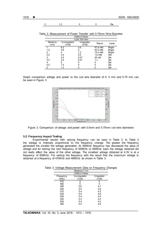
3.1. Testing Effect of Coil Wire Diameter
In this test important section of a sender and receiver circuit in the form of a coil size
of 0.5 mm for the first test and 0,75mm for the second test. Based on Table 1 and 2 it is seen
that for the diameter of 0.75 mm wire and the distance of 1 cm, there is a voltage of 2.6 volts at
the Vregulator point. Whereas for 0.5 mm wire diameter obtained voltage 2.1 volts. For lamp
conditions, 0.5 mm wire diameter and 2 cm distance of the lights have begun to fade while for
0.75 mm wire diameter the lights begin to fade at a distance of 2.5 cm. Maximum power transfer
generated amounted to 67.6 mWusing a 0.75 mm diameter wire. Whereas for 0.5 mm wire
diameter the maximum power that can be generated is 44.1 mW. For optimal power transfer
using 0.75 mm diameter wire because at a distance of 1 cm to 2 cm bright light conditions and
the resulting voltage is quite large when compared with 0.5 mm wire diameter.
Table 1. Measurement of Power Transfer with 0.5mm Wire Diameter
AWG 0.5mm
Load 100 ohm
Distance
(cm)
Vunregulator
(Volt)
Vregulator
(Volt)
Pow er Lamp
1 5.8 2.1 44.1 mW Bright
1.5 4.4 1.8 32.4 mW Bright
2 3.4 1 10 mW Dim
2.5 2.8 0.07 49 uW Die
3 2.6 0.01 1 uW Die
3.5 2.4 0 0 Die
4 2 0 0 Die
4.5 1.6 0 0 Die](https://image.slidesharecdn.com/117686-200824022603/85/Development-of-a-Wireless-Power-Transfer-Circuit-Based-on-Inductive-Coupling-3-320.jpg)
![ ISSN: 1693-6930
TELKOMNIKA Vol. 16, No. 3, June 2018 : 1013 – 1018
1018
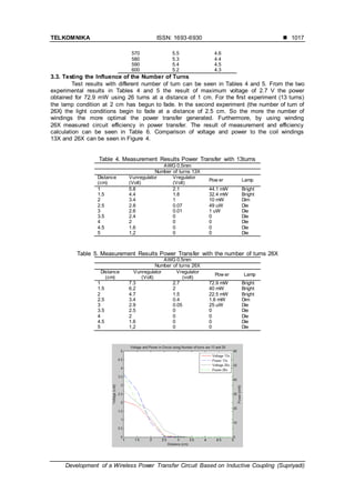
Figure 4. Comparison of voltage and power with coil windings 13X and 26X
Table 6. Transfer Efficiency Calculation
Distance
(cm)
Vinput
(V)
Iinput Pnput
(W)
Voutput
(V)
R
(Ω)
Poutput
(mW)
η (Efficiency)
1 12 0.4 4.8 2.7 100 72.9 1.52%
1.5 12 0.4 4.8 2 100 40 0.83%
2 12 0.4 4.8 1.5 100 22.5 0.47%
2.5 12 0.4 4.8 0.4 100 1.6 0.03%
3 12 0.4 4.8 0.05 100 0.025 0.0005%
3.5 12 0.4 4.8 0 100 0 0.0%
4 12 0.4 4.8 0 100 0 0.0%
4.5 12 0.4 4.8 0 100 0 0.0%
5 12 0.4 4.8 0 100 0 0.0%
4. Conclusion
The effect of wire diameter (AWG) used is directly proportional to the amount of power
that can be transferred. The larger the diameter of the wire used, the greater the power
transferred. The effect of the number of turns used is directly proportional to the amount of
power that can be transferred. The more the number of windings used the greater the power
transferred. The final series used using email wire of 0.5mm diameter, the number of turns 26X,
the input frequency of 470KHz. The power efficiency transferred at a distance of 1 cm is about
1.51%. The result of the experiment can turn on 1 Watt LED lamp.
References
[1] E Wong. A Review on Technologies for Wireless Electricity. Hongkong. 2013.
[2] TV Wilson. How Wireless Power Works. 1 Juni 2014. [Online]. [Accessed 2016].
[3] A Yudhana, F Djohar. Design of Handphone Wireless Charger System Using Omnidirectional
Antenna. TELKOMNIKA (Telecommunication, Computing, Electronics and Control). 2017; 15(4):
1757-1765.
[4] E Husni, Kuspriyanto, NC Basjaruddin. Mobile Payment Protocol tag-to-tag Near Field
Communication (NFC). iJIM. 2012; 6(4).
[5] E Husni, NC Basjaruddin, Kuspriyanto, T Purboyo, S Purwantoro, H Ubaya. Efficient tag-to-tag Near
Field Communication (NFC) Protocol for Secure Mobile Payment. in ICICI-BME. Bandung. 2011.
[6] SS Valtchee, EN Baikova, LR Jorge. Electromagnetic Field as the Wireless Transporter of Energy.
Facta Universitatis Ser. Electrical Engineering. 2012; 25(3): 171-181.
[7] R Puers.Omnidirectional Inductive Powering for Biomedical Implants. Springer Science & Business
Media. 2008.
[8] P Marks. Wireless charging for electric vehicles hits the road. 2014. [Online]. Available:
https://www.newscientist.com/article/mg22129534.900-wireless-charging-for-electric-vehicles-hits-
the-road/. [Accessed 1 Juni 2017].
[9] A Kumar. WiTricity : Wireless Power Transfer By Non-radiative Method. International Journal of
Engineering Trends and Technology (IJETT). 2014.
[10] A Gopinath. All About Transferring Power Wirelessly. Electronics For You E-zine (EFY Enterprises
Pvt. Ltd.), 2015: 52-56.
[11] M Fareq, M Fitra, M Irwanto, S HS, N Gomesh, M Rozailan, M Arinal, Y Irwan, J Zarinatul. Wireless
Power Transfer by Using Solar Energy. TELKOMNIKA (Telecommunication, Computing, Electronics
and Control). 2014; 12(3): 519-524.
[12] EDZY Xiaoming Liu. Power Characteristics of Wireless Charging for Sensor. TELKOMNIKA
(Telecommunication, Computing, Electronics and Control). 2015; 13(4): 1180~1186.
[13] I Darmawan. Pengembangan Inverter 12 VDC ke 220 VAC 50Hz dengan Penguat Akhir H-Bridge
Mosfet. Universitas Indonesia Departemen Teknik Elektro, Depok. 2012.](https://image.slidesharecdn.com/117686-200824022603/85/Development-of-a-Wireless-Power-Transfer-Circuit-Based-on-Inductive-Coupling-6-320.jpg)