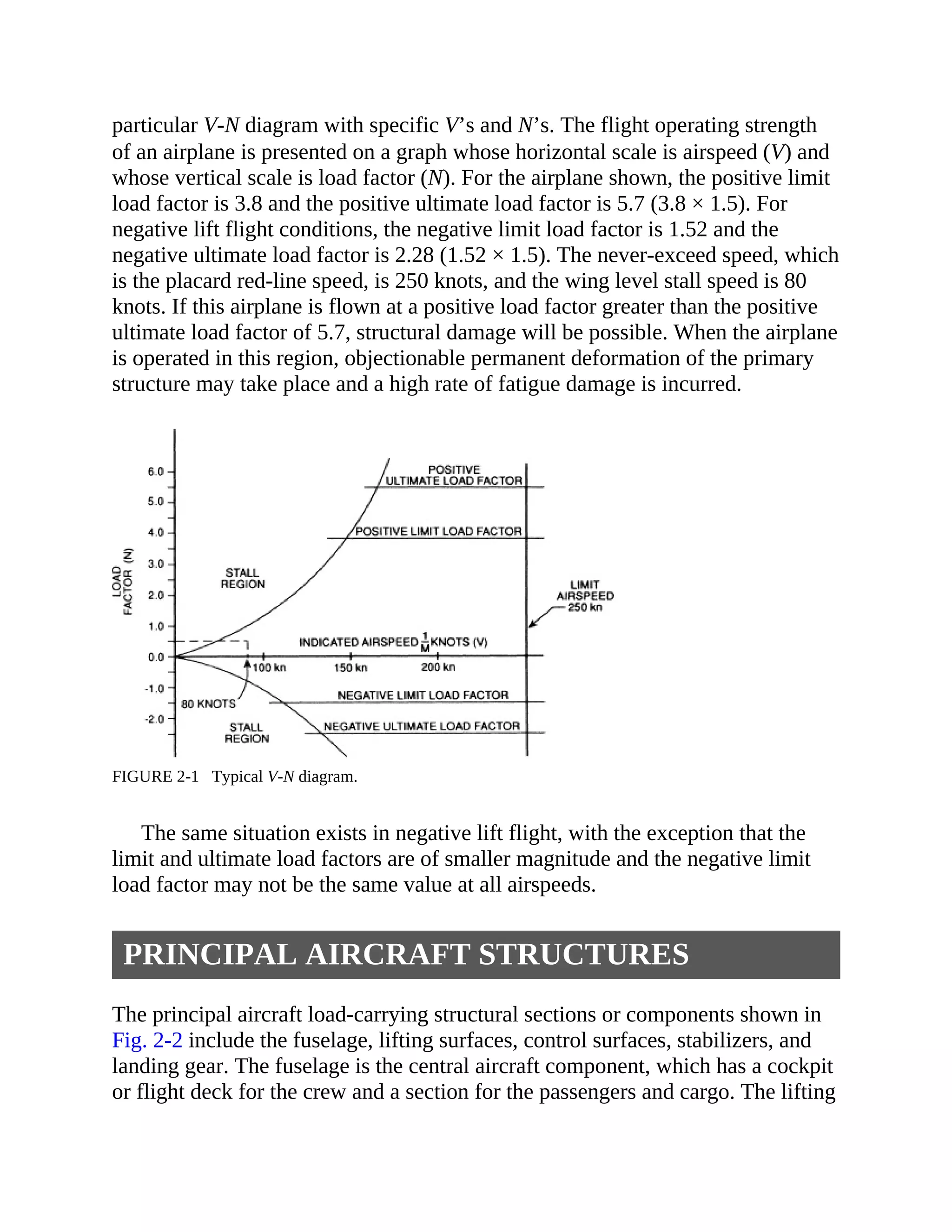
Aircraft
Maintenance and Repair
Aircraft
Maintenance and Repair
Seventh Edition
Michael J. Kroes
William A. Watkins (Deceased)
Frank Delp (Deceased)
Ronald Sterkenburg
New York Chicago San Francisco Lisbon London Madrid Mexico City Milan New Delhi San
Juan Seoul Singapore Sydney Toronto
Copyright © 2013 by The McGraw-Hill Education, Inc. All rights reserved. Except as permitted under the
United States Copyright Act of 1976, no part of this publication may be reproduced or distributed in any
form or by any means, or stored in a database or retrieval system, without the prior written permission of
the publisher.
ISBN: 978-0-07-180151-5
MHID: 0-07-180151-0
e-Book conversion by Cenveo® Publisher Services.
Version 1.0
The material in this eBook also appears in the print version of this title: ISBN: 978-0-07-180150-8, MHID:
0-07-180150-2.
McGraw-Hill eBooks are available at special quantity discounts to use as premiums and sales promotions,
or for use in corporate training programs. To contact a representative please e-mail us at
bulksales@mcgraw-hill.com.
All trademarks are trademarks of their respective owners. Rather than put a trademark symbol after every
occurrence of a trademarked name, we use names in an editorial fashion only, and to the benefit of the
trademark owner, with no intention of infringement of the trademark. Where such designations appear in
this book, they have been printed with initial caps.
Information has been obtained by McGraw-Hill from sources believed to be reliable. However, because of
the possibility of human or mechanical error by our sources, McGraw-Hill, or others, McGraw-Hill does
not guarantee the accuracy, adequacy, or completeness of any information and is not responsible for any
errors or omissions or the results obtained from the use of such information.
TERMS OF USE
This is a copyrighted work and The McGraw-Hill Education, Inc. (“McGraw-Hill”) and its licensors reserve
all rights in and to the work. Use of this work is subject to these terms. Except as permitted under the
Copyright Act of 1976 and the right to store and retrieve one copy of the work, you may not decompile,
disassemble, reverse engineer, reproduce, modify, create derivative works based upon, transmit, distribute,
disseminate, sell, publish or sublicense the work or any part of it without McGraw-Hill’s prior consent. You
may use the work for your own noncommercial and personal use; any other use of the work is strictly
prohibited. Your right to use the work may be terminated if you fail to comply with these terms.
THE WORK IS PROVIDED “AS IS.” McGRAW-HILL AND ITS LICENSORS MAKE NO
GUARANTEES OR WARRANTIES AS TO THE ACCURACY, ADEQUACY OR COMPLETENESS
OF OR RESULTS TO BE OBTAINED FROM USING THE WORK, INCLUDING ANY
INFORMATION THAT CAN BE ACCESSED THROUGH THE WORK VIA HYPERLINK OR
OTHERWISE, AND EXPRESSLY DISCLAIM ANY WARRANTY, EXPRESS OR IMPLIED,
INCLUDING BUT NOT LIMITED TO IMPLIED WARRANTIES OF MERCHANTABILITY OR
FITNESS FOR A PARTICULAR PURPOSE. McGraw-Hill and its licensors do not warrant or guarantee
that the functions contained in the work will meet your requirements or that its operation will be
uninterrupted or error free. Neither McGraw-Hill nor its licensors shall be liable to you or anyone else for
any inaccuracy, error or omission, regardless of cause, in the work or for any damages resulting therefrom.
McGraw-Hill has no responsibility for the content of any information accessed through the work. Under no
circumstances shall McGraw-Hill and/or its licensors be liable for any indirect, incidental, special, punitive,
consequential or similar damages that result from the use of or inability to use the work, even if any of them
has been advised of the possibility of such damages. This limitation of liability shall apply to any claim or
cause whatsoever whether such claim or cause arises in contract, tort or otherwise.
About the Authors
Michael J. Kroes has been an aviation practitioner and educator for over 35
years. He has held various FAA certifications, including Airframe and
Powerplant Mechanic, Inspection Authorization, Designated Mechanic
Examiner, and Designated Engineering Representative, and he holds a
commercial pilot license. Mr. Kroes has worked for some of the leading aviation
companies, including Raytheon and Allied Signal, and has also spent 25 years as
a professor and department head at Purdue University. Recognized as a leading
expert on FAA technician certification, he authored a comprehensive study
funded by the FAA. This study was used to develop new FAA technician
certification content and guidelines. Mr. Kroes resides in Pinehurst, North
Carolina.
Ronald Sterkenburg is a professor in the Aviation Technology Department at
Purdue University. He is a certificated Airframe and Powerplant (A&P)
Mechanic, holds an Inspection Authorization (IA), and is a Designated Mechanic
Examiner (DME). Although his main research interests are in advanced
composite materials for aerospace vehicles, he has published many articles, book
chapters, and books on all types of aviation maintenance topics. Dr. Sterkenburg
resides in West Lafayette, Indiana.
Contents
Preface to the Seventh Edition
Preface to the Sixth Edition
1. Hazardous Materials and Safety Practices
Hazardous Materials
OSHA’s Hazardous Communications Standards
Disposal and Accidental Releases of Hazardous Materials
Review Questions
2. Aircraft Structures
Aircraft Structural Design
Principal Aircraft Structures
Aircraft Station Numbers
Zoning
Nomenclature and Definitions
Fuselages
Cockpits, Cabins, and Compartments
Wings
Tail and Control Surfaces
Landing Gear
Powerplant Structures
Rotorcraft Structures
Review Questions
3. Fabrication and Repair of Wood Structures
Aircraft Woods
Adhesives and Bonding Procedures
Construction and Repair of Wood Structures
Care of Aircraft with Wood Structures
Inspection of Airplanes Having Wood Structures
Review Questions
4. Fabric Coverings
Fabric Types and Terminology
Dopes and Finishing Materials
Facilities and Equipment for Aircraft Covering
Selection of Fabric Covering Material
Application of Fabric Covers for Aircraft
Fabric Inspection
Repair of Fabric Coverings
Review Questions
5. Aircraft Painting and Markings
Aircraft Finishing Materials
Spray-Paint Equipment
Finishing Metal Aircraft and Parts
Registration Marks for Aircraft
Review Questions
6. Welding Equipment and Techniques
Fundamentals of Welding
Oxyacetylene Welding
Gas Welding Techniques
Electric-Arc Welding
Inert-Gas Welding
Conclusion
Review Questions
7. Welded Aircraft Structures and Repair
Construction of Steel-Tube Assemblies by Welding
Inspection of Steel-Tube Structures
Aircraft Tubing Repair
Special Welding Repairs
Soldering and Brazing
Review Questions
8. Sheet-Metal Construction
Design Philosophies
Factors Affecting Sheet-Metal Part and Joint Design
Fundamental Calculations for Structures
Bending Metals
Preparation for Layout Work
Hand Tools for Sheet-Metal Work
Floor and Bench Machinery for Sheet-Metal Work
Fabrication of Sheet-Metal Parts
Riveting
Review Questions
9. Sheet-Metal Inspection and Repair
Sheet-Metal Inspection
Sheet-Metal Repair
Repair Practices
Rivet-Repair Design
Review Questions
10. Plastics
Fundamentals of Plastic Materials
Working with Plastic Materials
Installation, Maintenance, and Repair of Plastic Materials
Review Questions
11. Advanced Composite Materials
Laminated Structures
Major Components of a Laminate
Strength Characteristics
Description of Sandwich Structures
Review Questions
12. Assembly and Rigging
Aircraft Assembly
Aircraft Rigging
Fixed-Surface Alignment
Aircraft Flight Controls
Secondary Flight-Control Surfaces
Control-System Components
Control Surface Rigging
Balancing Control Surfaces
Inspection and Maintenance
Helicopter Flight Controls
Review Questions
13. Aircraft Fluid Power Systems
Principles of Hydraulics
Hydraulic Fluids
Hydraulic Reservoirs
Hydraulic Filters
Hydraulic Pumps
Pressure-Control Devices
Pressure-Reducing Valves
Accumulators
Selector Valves
Automatic-Operating Control Valves
Hydraulic Actuators
Hydraulic Plumbing Components
Hydraulic Systems for Aircraft
Hydraulic System for the Boeing 777 Airliner
Hydraulic System for the Airbus 380
Hydraulic System for the Bell 214ST Helicopter
Pneumatic Systems for Aircraft
Summary of Hydraulic System Maintenance Practices
Review Questions
14. Aircraft Landing-Gear Systems
Landing-Gear Configurations
Classification of Landing Gear
Landing-Gear Components
Steering Systems
Retraction Systems
Transport Aircraft Landing-Gear Systems
Inspection and Maintenance of Landing Gear
Tires and Wheels
Design and Operation of Brake Assemblies
Aircraft Brake Systems
Brake Maintenance
Review Questions
15. Aircraft Fuel Systems
Requirements for Fuel Systems
Fuel Tanks
Fuel-System Components
Types of Fuel Systems
Fuel Subsystems
Typical Aircraft Fuel Systems
Inspection, Maintenance, and Repair of Fuel Systems
Troubleshooting
Review Questions
16. Environmental Systems
Heating Systems
Cabin-Cooling Systems
Cabin-Pressurization Systems
Cabin Environmental System for a Jet Airliner
Summary of Pressurization and Air-Conditioning Systems
Oxygen Systems
Review Questions
17. Aircraft Instruments and Instrument Systems
Principles of Instrument Operations
Flight Instruments
Flight Instrument Systems
Engine Instruments
Fuel-Quantity Indicators
Fuel-System-Monitoring Instruments
Miscellaneous Instruments
Electronic Instruments
Installation and Maintenance of Instruments
Review Questions
18. Auxiliary Systems
Fire Protection Systems
Ice Protection Systems
Rain-Removal Systems
Water and Waste Systems
Position and Warning Systems
Auxiliary Power Units
Review Questions
19. Troubleshooting Theory and Practice
The Troubleshooting Process
Format of Troubleshooting Charts
Review Questions
Index
Color Insert
Preface to the Seventh Edition
In preparing this edition, the authors reviewed FAR Parts 65 and 147, FAA-H-
8083-30 & 31, AC 43.13-1B & 2B, and manufacturers’ and operators’ manuals
and data to ensure that all required areas of study were included.
This revised edition updates material from the previous edition relating to
aircraft structures and systems on current operational aircraft. Figures, charts,
and photos have been updated to reflect new technology. The advanced
composite materials chapter has been completely rewritten to reflect state-of-the-
art maintenance and repair information and techniques for advanced composite
structures used in modern aircraft. Advanced automated systems such as ECAM
and EICAS are discussed in most chapters to reflect their operation relative to
particular aircraft systems. The structures chapter has been expanded with
multiple examples for the calculation of bend allowance and the setup of shop
equipment. The hydraulics chapter has been expanded to include the 5000-psi
hydraulic systems used in some new aircraft models. A discussion of a
centralized fault display system (CFDS) has been added to the troubleshooting
chapter.
Michael J. Kroes
Ronald Sterkenburg
Preface to the Sixth Edition
Aircraft Maintenance and Repair is designed to provide aviation students with
the theoretical and practical knowledge required to qualify for certification as
FAA airframe technicians in accordance with Federal Aviation Regulations
(FARs). This text covers the subjects categorized in the FARs under Airframe
Structures and Airframe Systems and Components and may be used as a study
text in connection with classroom discussions, demonstrations, and practical
application in the shop and on aircraft.
Aircraft Maintenance and Repair is one of five textbooks in the McGraw-Hill
Aviation Technology Series. The other books in the series are Aircraft
Powerplants, Aircraft Basic Science, Aircraft Electricity and Electronics, and
Aircraft Gas Turbine Engine Technology. Used together, these texts provide
information dealing with all prominent phases of aircraft maintenance
technology.
In preparing this edition, the authors reviewed FAR Parts 65 and 147,
Advisory Circular (AC) 65-2D, AC 65-15A, and AC 43.13-1A & 2A to ensure
that all required areas of study were included. Related FARs and the
recommendations and suggestions of aviation maintenance instructors, aircraft
manufacturers, aviation operators, and maintenance facilities were given full
consideration in the revision of this text.
This revised edition retains material from the previous edition relating to
structures and systems that are employed on current operational aircraft. In
addition, information dealing with expanding and emerging maintenance-related
technologies has been incorporated to provide a comprehensive source of
information for the aviation student, technician, and instructor. Two new
chapters have been added. They include information about the identification of
hazardous materials, their storage, use, and disposal. Troubleshooting has been
identified as its own process and is discussed generically.
Key revisions to and the expansion of the previous edition include designing
repairs so that the repairs are repairable and techniques in designing repairs
based upon the mechanical properties of the materials. Also, bend allowance
calculations and terminology have been revised to follow the more traditional
industry conventions.
Each topic covered in this series of texts is explained in a logical sequence so
students may advance step by step and build a solid foundation for performing
aviation maintenance activities. Students’ understanding of the explanations and
descriptions given in the text should be enhanced by the use of numerous
photographs, line drawings, and charts. Review questions at the end of each
chapter enable students to check their knowledge of the information presented.
In addition to being a classroom and shop instruction text, the book is
valuable for home study and as an on-the-job reference for the technician. The
materials in this text and in others in the series constitute a major source of
technical knowledge for technical schools and colleges and universities.
Although this text is designed to provide information for the training of
aviation personnel, the user must realize that product and aircraft manufacturers
establish guidelines and procedures for the correct use and maintenance of their
product or aircraft. Therefore, it is the responsibility of the user of the text to
determine and follow the specific procedures recommended by the manufacturer
when handling a specific product or when working on a specific aircraft or
component.
Michael J. Kroes
William A. Watkins
Hazardous Materials and Safety
Practices
1
AUTHORS’ NOTE
Although every effort has been made to ensure that the regulations and standard
practices referred to in this text are current, recommended safety practices and
associated regulations are always subject to change. Since the distribution of this
book is not controlled, revisions to all existing copies is impossible. As a result,
the technical information, such as material safety data sheets, is included only
for educational purposes and should not be used in application. In addition, there
are applications that are unique in one aspect or another. In these cases the
recommended practices may differ from those used as general industry standard.
Before attempting any activity, the aviation maintenance technician should
review the most recent regulations, recommended practices prescribed by their
employer, the associated equipment manufacturer’s recommendations, and the
information provided by the manufacturers of any supplies being used.
INTRODUCTION
There are many specialized careers available to today’s aviation maintenance
technician. As with any technical career, each career path has associated with it
activities that can subject the technician and others to varying degrees of harm if
performed without care. This chapter is intended to help the aviation
maintenance technician identify potentially hazardous materials and ways in
which the potential for harm can be minimized.
Today there are tens of thousands of products used in industry, with more
being developed each day. Numerous governmental agencies (and, therefore,
hundreds of governmental regulations) control the development, safety
requirements, and health and environmental issues related to these products. Key
among these agencies are the Consumer Product Safety Commission (CPSC),
the Food and Drug Administration (FDA), the Department of Transportation
(DOT), the Environmental Protection Agency (EPA), and the Occupational
Safety and Health Administration (OSHA). Although all these agencies have
some effects that may be felt in the aviation industry, the primary impact results
from the last three organizations mentioned.
Some Federal Air Regulations (FARs) refer to the DOT standards in their text
and use these standards as the criteria with which the aviation industry must
comply. In addition, as users of potentially dangerous chemicals, the aviation
industry must comply with both the regulations of the EPA as they relate to
environmental concerns and OSHA as their usage relates to the safety and health
of its employees.
Since the aviation industry is by its nature predominantly interstate
commerce, most businesses in the aviation industry are subject to federal
regulations. In addition, most state and some local governments have also passed
safety and environmental related legislation that parallels or supplements federal
legislation. As a result, the regulations associated with each are quite similar.
Regardless of which jurisdiction applies to the operations of the aviation
business, the operation must comply with some type of hazardous-materials
regulation. In some instances, more than one jurisdiction may control the
operations of the business.
Because of the vastness of this subject area and the general duplication of
regulations between federal, state, and local governments, discussions in this
chapter are limited to federal regulations and generic handling of hazardous
materials. In addition to the information found in this chapter, in later chapters
the aviation maintenance technician will find more safety data related to the
specific types of equipment and/or processes as they are discussed throughout
the text.
HAZARDOUS MATERIALS
The aviation maintenance technician frequently must work in potentially
dangerous environments. In many cases, particularly when dealing with
hazardous materials, the technician may not easily recognize those hazards.
Some of these dangerous environments may be caused directly by the materials
with which the aviation maintenance technician must work. In addition,
exposures may be caused by other activities occurring in the area that are not
directly related to the technician’s activities.
Hazardous materials are typically grouped into three categories: chemical
agents, and physical and biological hazards.
Chemical Agents
Within the chemical agents category, four classes exist. Comprehensive Loss
Management, Inc., a professional developer of and consultant for safety and
health awareness systems headquartered in Minneapolis, Minnesota, has trade-
marked the acronym FACTOR™ to help remember the classes of chemical
agents. Much of the information in this chapter comes from and is included in
their programs. Because each class of chemical agent requires different usage,
handling, and storage techniques, it is important that the aviation maintenance
technician be able to recall and identify each of these classes. FACTOR™ stands
for
Flammable
And
Corrosive
Toxic
Or
Reactive
The two outside letters of the acronym FACTOR, F and R (flammable and
reactive), become hazardous primarily after some outside event, condition, or
substance interacts with them. For example, the necessary components for a fire
to occur are fuel, oxygen, and heat. In that relationship, flammables are the fuel,
and heat and oxygen are the outside agents. Reactives, when combined with
certain other materials, are capable of generating heat and/or gases, causing an
explosion.
The inside letters of the acronym, C and T (corrosives and toxins), on the
other hand, act directly on the human body when exposure occurs. Exposing the
skin, eyes, and other mucous membranes (such as the nose) to these elements
can cause varying degrees of harm. Toxic agents cause poisoning. Aviation
maintenance technicians should be particularly concerned when using toxic
agents, because the ultimate effects of toxic poisoning are frequently delayed. It
may take weeks, months, or even years for the poisoning to become apparent;
because the toxic poisons are capable of using the bloodstream to move through
the body, the cause-and-effect relationship may not be easily recognized.
As a general rule, when working with flammable and reactive agents, to
avoid hazardous situations the aviation maintenance technician first needs to be
concerned with exposing the agents to outside materials and conditions. Personal
exposure to corrosive and toxic agents is the primary concern when dealing with
toxins and corrosives. Therefore, the personal safety equipment used with
corrosive and toxic agents should be designed to limit contact and/or exposure.
Personal safety equipment designed for use with flammable and reactive
materials is designed to limit heat exposure or impact, such as flying objects in
the case of an explosion. In all cases, the recommended safety equipment
recommended by the agent manufacturer, the employer, or the instructor should
always be used.
Table 1-1 is a partial listing of frequently used chemical agents found in the
aerospace industry. The aviation maintenance technician should be aware of the
labels on the materials found in the work area and read them carefully.
Flammables (and Combustibles)
Flammables are materials that may easily ignite in the presence of a catalyst
such as heat, sparks, or flame. They may be in any of the three physical forms:
solid, liquid, or gas. Combustible liquids are very similar to flammable liquids,
but they are not as easy to ignite.
Frequently found flammable or combustible materials in the aviation
industry include fuels, paint-related products, alcohols, acetone, toluene, and
some metal filings.
Generally Recommended Personal Safety Equipment
• Fire-retardant clothing
• Fire extinguisher
Handling and Storage
• Limit access to open flames, sparks, hot surfaces, etc. Note: Static electricity
may produce sparks. To avoid sparks, containers should be grounded.
• Limit quantities to the minimum needed to accomplish the desired task.
• Store the materials in approved containers only and in designated areas only.
• Store flammable toxins and corrosive toxic materials separately. The
corrosive gases could attack the flammable containers, eventually leading to a
leak of flammable materials.
Typical Emergency Procedures
• Turn off electrical equipment or any other potential source of sparks.
• Attempt to close shutoff valve(s).
• Remove container(s) from the area.
• For large spills, leave the area immediately and notify your supervisor.
• In case of direct contact with skin or eyes, rinse immediately with water.
• If toxic substances are inhaled, go to a fresh-air area.
• If contact is made through clothing, remove wet clothing and store it in a
proper container.
• Do not attempt to remove the substance with compressed air.
Corrosives
Corrosive materials are materials that can react with metallic surfaces and/or
cause burning of the skin.
Frequently found corrosives in the aviation industry include acids and bases,
such as battery acids and metal-cleaning solutions. Strong acids are most
normally found in a liquid form, whereas bases tend to come in powdered form.
Generally Recommended Personal Safety Equipment
• Gloves, aprons, respirator, face shield or goggles, and, sometimes, protective
footwear.
Handling and Storage
• Containers must be corrosive resistant.
• Eye (goggles and/or face shields) and skin protection (such as gloves) should
always be worn.
• Never add water to acid.
• Acids and bases should be stored separately.
• Eye washes and showers should be easily accessible to the work area.
• Flammable toxins and corrosive toxic materials should be stored separately.
The corrosive gases could attack the flammable containers, eventually leading
to a leak of flammable materials.
Typical Emergency Procedures
• Remove any corrosives that have come in contact with your skin or eyes by
rinsing with fresh water (approximately 15 minutes).
• Remove any contaminated clothing.
• Go to fresh air area.
• Ventilate area.
• Check safety equipment before attempting to stop the flow of spillage by
creating a dam.
• If swallowed, DO NOT INDUCE VOMITING. Drink large amounts of water.
Seek medical attention immediately.
Toxins
Toxins are generally defined as any substance that can cause an illness or injury.
The effects of toxins, unlike flammables and corrosives, may appear all at once
(called acute effects) or may build up over time with additional exposure
(chronic effects). Some toxins may dissipate over time when further exposure is
eliminated, while others remain in a human’s system, even after death.
Frequently found toxins in the aviation industry may be grouped into eight
categories.
1. Solvents and thinners for bluing (such as Dykem), paints, ketones, and
adhesives.
2. Solids such as metal dust or asbestos. Compressed air should never be
used to clean metal dust from equipment or clothing. The use of compressed air
may result in minute particles of material being embedded in the pores of the
skin.
3. Machine lubricants, cutting fluids, and oils.
4. Gases such as carbon dioxide or nitrogen. These gases may not only
possess a toxic nature but also displace the oxygen normally found in the air.
5. Polymers, epoxies, and plastics. Although not normally toxic in their final
form, these materials possess toxic properties during the fabrication process.
6. Sensitizers, such as epoxy systems. Such materials react with and may
destroy portions of the body’s immune system. The effects of sensitizers may be
cumulative, so minimal levels of exposure are recommended.
7. Carcinogens. Carcinogens may cause changes in the genetic makeup of a
human cell, resulting in cancer. Although the use of carcinogens is rare in the
aviation industry, aviation maintenance technicians associated with cargo
aircraft should pay particular attention to the cargo manifest before cleaning
spillage.
8. Reproductive hazards, such as carcinogens. These hazards are rare in the
aviation industry. Such materials may either interfere with the reproductive
process (as in the cases of DBCP) or affect the developing process of the fetus
(such as dimethyl acetamide).
Generally Recommended Personal Safety Equipment
• Gloves, aprons, respirator, face shield or goggles, and, sometimes, protective
footwear are recommended.
• Be sure to use the environmental control systems that may already be in place,
such as ventilation fans and filters.
Handling and Storage
• Minimize the release of toxic agents into the environment by capping all
containers and storing them in properly ventilated areas. When toxins are used
in open containers, such as dip tanks and trays, their surface areas should be
kept to a minimum in order to reduce the rate of evaporation into the
surrounding environment.
• Flammable toxins and corrosive toxic materials should be stored separately.
The corrosive gases could attack the flammable containers, eventually leading
to a leak of flammable materials.
Typical Emergency Procedures
• If there is any doubt in your mind regarding the degree of toxicity of the
substance spilled, LEAVE THE AREA IMMEDIATELY AND NOTIFY
YOUR SUPERVISOR.
• Generally speaking, if the spillage is less than 1 gal, it may be cleaned up by
wiping it up with absorbent materials.
Reactives
Reactive agents are those materials that react violently with other materials (not
necessarily solids). The reactions that may take place range from violent
explosions to the emission of heat and/or gases.
The following reactives are frequently found in the aviation industry:
1. Oxidizers, which add oxygen to situations where high levels of heat and
burning are present
a. Peroxides
b. Perchloric acid and chromic acid
c. Halogens, such as bromine and iodine
2. Water-reactive materials, such as lithium, react with water and form
hydrogen gases, which are very explosive.
Examples of incompatible reactive materials include
• Cyanides (frequently used in plating) and acids
• Chloride bleach and ammonia (this combination forms highly toxic chlorine
gas)
Generally Recommended Personal Safety Equipment
• Gloves, aprons, respirator, and face shield or goggles are suggested.
• Be sure to use the environmental-control systems.
Handling and Storage
• Store reactive materials in a location separate from other materials. Always
review the MSDS (material safety data sheet) for incompatible materials.
• Many reactives are both toxic and corrosive.
Typical Emergency Procedures
• Shut down electrical equipment whenever possible.
• If there is any doubt in your mind regarding the degree of reactivity and
toxicity of the substances involved, LEAVE THE AREA IMMEDIATELY
AND NOTIFY YOUR SUPERVISOR.
Material Compatibility with Chemical Agents
Before leaving the topic of chemical agents, it is important to realize that
although some materials meet the minimum standards for protective equipment
in particular applications, other materials surpass these requirements. Table 1-2
lists various types of protective equipment materials and their relative
effectiveness when used with common chemical agents. Although Table 1-2
provides generally accepted data, the aviation maintenance technician should
always consult the MSDS, discussed later in this chapter, for specific protective
equipment requirements.
Physical Hazards
Physical hazards are those to which the aviation maintenance technician is
exposed that are usually caused by the use of some type of equipment not
directly controllable by the technician. Typically, this type of hazard is generated
by the operation of equipment that can be detected by the human senses.
However, many physical hazards that fall into this classification are not
detectable by the human senses. These hazards include X rays, microwaves, beta
or gamma rays, invisible laser beams, and high-frequency (ultrasonic) sound
waves.
Compressed liquids and gases, such as welding oxygen and acetylene,
aviator’s breathing oxygen, nitrogen, and hydraulic accumulators, present
another physical hazard to the aviation maintenance technician. Although some
of these substances by themselves present hazards as chemical agents, placing
them under pressure may create another unique hazard.
OSHA requires that areas where this exposure exists be clearly marked and
that individuals exposed to these hazards be provided the proper safety
equipment. In many cases this is easily accomplished, but in the aerospace
industry particular concern should be paid to portable equipment that generates
these hazards. Such equipment results in the potential for hazards to exist in
areas where exposure is not usually a concern. X ray of aircraft structural parts is
an example of such a situation. The aviation maintenance technician should
remain conscious that potentially hazardous equipment is portable and remain
vigilant for possible exposure in the work area.
Biological Hazards
Biological hazards, although not normally a major concern to the aviation
maintenance technician, may occasionally exist in the work environment.
Biological hazards are living organisms that may cause illness or disease. Some
biological hazards also have toxic by-products. Typically, biological hazards are
transmitted in the form of air droplets or spores and enter the body through
contact with contaminated objects or individuals.
The practicing aviation maintenance technician in the workplace would most
likely be exposed to biological hazards when working on cargo aircraft or in a
cargo (baggage) compartment where breakage or leakage of biologically
hazardous materials has occurred. FAA regulations require that the
transportation of biologically hazardous materials be documented. When in
doubt about the presence of such materials, the aviation maintenance technician
should consult the aircraft’s record, possibly including the cargo manifest.
OSHA’S HAZARDOUS COMMUNICATIONS
STANDARDS
In 1983, the first regulation requiring employers to advise employees of
potentially hazardous materials in the work place was established. This standard,
the Hazardous Communications Standard (29 CFR 1910.1200), was established
by OSHA and has since been expanded to include almost all employers. The law
requires that all employees and their supervisors be informed about the known
hazards associated with the chemicals with which they work, regardless of the
quantity of the chemicals involved in the operation. These requirements are part
of the various right-to-know regulations. As part of these right-to-know
regulations, employers are required to post a notice similar to that shown in Fig.
1-1.
FIGURE 1-1 Right-to-know poster.
There are five basic requirements of a hazard-communications program:
1. Inventory. An inventory (list) of all hazardous materials used within the
workplace must be established and maintained.
2. Labeling. All hazardous chemicals shall be properly labeled.
3. Material safety data sheets (MSDSs). Material safety data sheets must be
obtained for all material stored and/or used in the work area. A copy of these
MSDSs must be maintained and made readily available to all employees during
normal working hours. MSDSs provide detailed information concerning
composition, health hazards, special handling instructions, and proper disposal
practices for materials.
4. Training. All employees must be provided training regarding their rights
under the right-to-know program, the proper handling of these materials, the
labeling system used, and detection techniques.
5. Written program. Each employer must establish a written program that will
comply with the four points just mentioned; this written program must be present
at the work facility.
Material Safety Data Sheets
A material safety data sheet (MSDS) is a document provided by the material
manufacturer or subsequent material processor that contains information related
to the material hazard and includes safe handling and disposal procedures. The
format of these sheets must be consistent with the requirements of the OSHA
Hazard Communications Standard. MSDSs should be provided by the
manufacturer for each hazardous material supplied by them. Normally MSDSs
are provided with each shipment of a hazardous material. If one is not provided
the technician should request one from the manufacturer. Most manufacturers
post their MSDSs on their websites. Figure 1-2 is an example of a 16-section
standardized MSDS. This format is used by most manufacturers.
FIGURE 1-2 Sample MSDS. (Sciencelab.com, Inc.)
The Occupational Safety and Health Administration (OSHA) specifies that
certain information must be included on MSDSs, but does not require that any
particular format be followed in presenting this information. OSHA recommends
that MSDSs follow the 16-section format established by the American National
Standards Institute (ANSI) for preparation of MSDSs.
By following this recommended format, the information of greatest concern
to workers is featured at the beginning of the data sheet, including information
on chemical composition and first aid measures. More technical information that
addresses topics such as the physical and chemical properties of the material and
toxicological data appears later in the document. While some of this information
(such as ecological information) is not required by the Hazard Communication
Standard (HCS), the 16-section MSDS is becoming the international norm.
As of June 1, 2015, MSDSs will be replaced by Safety Data Sheets (SDSs).
The HCS will require chemical manufacturers, distributors, or importers to
provide SDSs to communicate the hazards of hazardous chemical products. The
new SDS will have a uniform format, and will include the section numbers, the
headings, and associated information under the headings below:
Section 1: Identification includes product identifier; manufacturer or distributor
name, address, phone number; emergency phone number; recommended use;
restrictions on use.
Section 2: Hazard(s) Identification includes all hazards regarding the
chemical; required label elements.
Section 3: Composition/Information on Ingredients includes information on
chemical ingredients; trade secret claims.
Section 4: First-Aid Measures includes important symptoms/effects (acute,
delayed); required treatment.
Section 5: Firefighting Measures lists suitable extinguishing techniques,
equipment; chemical hazards from fire.
Section 6: Accidental Release Measures lists emergency procedures; protective
equipment; proper methods of containment and cleanup.
Section 7: Handling and Storage lists precautions for safe handling and
storage, including incompatibilities.
Section 8: Exposure Controls/Personal Protection lists OSHA’s Permissible
Exposure Limits (PELs); Threshold Limit Values (TLVs); appropriate
engineering controls; personal protective equipment (PPE).
Section 9: Physical and Chemical Properties lists the chemical’s
characteristics.
Section 10: Stability and Reactivity lists chemical stability and possibility of
hazardous reactions.
Section 11: Toxicological Information includes routes of exposure; related
symptoms; acute and chronic effects; numerical measures of toxicity.
Section 12: Ecological Information*
Section 13: Disposal Considerations*
Section 14: Transport Information*
Section 15: Regulatory Information*
Section 16: Other Information includes the date of preparation or last revision.
Inventory
Even though many companies inventory the materials they use, a special
inventory of hazardous materials must be maintained. Each item in the inventory
should include the name of the hazardous material, location, and the
approximate (or average) quantity in each area.
Materials sold in consumer form are not normally controlled. For example, if
the aviation maintenance technician purchases a painted aluminum cover plate in
a ready-to-install form, no MSDS would accompany the product. However, if
the aviation maintenance technician purchases the aluminum sheet and paint
separately, to fabricate the product, it is likely that an MSDS would accompany
both the aluminum sheet and the paint.
Labeling
All hazardous materials should have identifying labels adhered to them. As a
general rule, these labels should never be removed. In instances where materials
are received in bulk form and transferred to small containers for use, two general
rules apply. First, the container should be clearly labeled. Second, once a
container is used for one hazardous substance, it should never be used to hold
another substance.
Probably the most common standardized hazardous materials identification
placard used today is that of the NFPA. Although this code is intended for the
use of firefighters during a fire emergency, it is another tool available to the
aviation maintenance technician that may be used to avoid hazardous situations.
This placarding system uses four diamonds to form another diamond (Fig. 1-3).
Each diamond position identifies the degree to which a particular type of hazard
is present.
FIGURE 1-3 NFPA placard. (Copyright © 1990, National Fire Protection Association, Quincy, MA
02269. This warning system is intended to be interpreted and applied only by properly trained individuals
to identify fire, health, and reactivity hazards of chemicals. The user is referred to a certain limited number
of chemicals with recommended classifications in NFPA 49 and NFPA 325M, which would be used as a
guideline only. Whether the chemicals are classified by NFPA or not, anyone using the 704 system to
classify chemicals does so at his/her own risk.)
The top three diamonds follow a numbering system from 1 to 4, indicating
the degree of hazard.
The topmost diamond specifies the relative fire hazard. The relative fire
hazard is a function of the temperature at which the material will give off
flammable vapors that will ignite when they come in contact with a spark or
flame. This temperature is called the flash point. Figure 1-3 also shows how the
number code is used to express the way in which the flash point ranges are
specified.
The left side of the diamond specifies the health hazard and the right side of
the diamond indicates the degree of the reactivity of the material.
The bottommost diamond indicates any specific hazard and, if more than one,
the major hazard that applies to this material.
This diamond coding system may also use different colors to segregate each
type of hazard.
The health hazard diamond is blue.
The flammability diamond is red.
The reactivity diamond is yellow.
The specific hazard diamond is white.
The aviation maintenance technician should be conscious of the environment
in which work is being accomplished. For example, aviation maintenance
technicians working in confined, poorly ventilated areas should use appropriate
precaution if the NFPA health hazard code is greater than 0. Aviation
maintenance technicians working on hot brakes or engines should beware of the
relative fire hazard code.
Many companies have their own labeling program. In cases where codes are
used, the company has the obligation to identify the coding system. An example
of a labeling system used by Weber Marking Systems of Arlington Heights, IL,
is shown in Fig. 1-4.
FIGURE 1-4 In-house labeling system. (Weber Marking Systems)
In-house labeling systems are most frequently used when the operations of
the company require the transferring of hazardous materials from one container
to another. In most cases, the in-house labeling is used in addition to the original
container labels.
Generic in-house labeling systems are also available commercially. A
commercially available hazardous materials identification system produced by
Labelmaster, an American Labelmark Company, Chicago, IL, is shown in Fig.
1-5. As with most marking systems, the degree of hazard severity is based upon
a numbering system. American also adds an index system using letters that
correspond to the recommended personal protective equipment for use with the
hazardous material.
FIGURE 1-5 Generic labeling system. (American Landmark Co.)
The majority of hazardous materials with which the aviation maintenance
technician will come in contact are complex mixtures of chemicals. Normally,
mixtures are analyzed as a whole to determine their physical properties and
health hazards, if any exist. If a mixture has not been tested as a whole, it is to be
considered hazardous if it contains more than 1 percent of any hazardous
material. In the case of carcinogens, the minimum component amount is 0.1
percent.
DISPOSAL AND ACCIDENTAL RELEASES OF
HAZARDOUS MATERIALS
Just as the Occupational Safety and Health Act was enacted to protect the health
of industrial workers, the National Environmental Policy Act of 1969 (NEPA)
was enacted to protect the environment. The NEPA established the
Environmental Protection Agency (EPA) to accomplish its objectives.
Businesses that use hazardous materials must be conscious of the hazards, not
only while using the materials but also when disposing of them. As part of the
employee’s orientation to hazardous materials, proper disposal techniques
should be addressed.
Creators of hazardous waste are responsible for the identification, separation,
labeling, packaging, storage, shipping, and disposal of the waste produced. The
EPA monitors the movement of hazardous waste from the time it is generated to
the time it reaches a licensed treatment, storage, and disposal facility (TSDF).
As part of this process, generators of hazardous waste must maintain detailed
records regarding hazardous-waste materials. It is therefore extremely important
that the aviation maintenance technician comply with the record-keeping
practices and procedures of the company.
Routine handling of hazardous materials is typically not a problem for the
aviation maintenance technician because the technician either is familiar with the
procedure or has time during which specific instruction may be obtained.
Accidental release of hazardous materials, however, is another story.
When an accidental release occurs, the typical reaction is one of panic. As
part of the employer training sessions, the aviation maintenance technician will
receive instructions regarding procedures to follow in case of an accidental
release, but these may not be remembered, particularly when an emergency
occurs.
Accidental releases most typically occur when the hazardous material is in a
liquid or gaseous state. It is important that the aviation maintenance technician
not equate hazardous materials with rarely used materials. Spillage of commonly
used hazardous materials such as aviation fuels and lubricants is also considered
an accidental release of a hazardous material.
Accidental releases, by definition, do not happen because they are planned.
However, because of their potential impact, the aviation technician should plan
for and anticipate their occurrence. Prior to using a hazardous material, the
aviation maintenance technician should evaluate the types of accidental releases
that might occur and prepare for them. A review of the MSDS prior to usage is
advised.
advised.
The aviation maintenance technician should be concerned first with personal
safety. If a release might have detrimental effect on other individuals, a means of
notification should be established. Containment is the next priority. This may
take a little imagination. For example, if the hazardous materials are in a tank,
how could a leak be stopped? If a drain shutoff value was dislodged, how could
the drain be quickly plugged?
The EPA has established reporting procedures for accidental release of
hazardous materials. Whether an accidental release needs to be reported is
determined by the quantity or concentration of material released. Calculations of
concentration may be rather complex and typically are beyond the capability of
the technician. Therefore, all accidental releases should be reported to the
aviation maintenance technician’s supervisor as soon as possible. Any
information the aviation maintenance technician has regarding the amount
released should be noted and submitted to the supervisor.
REVIEW QUESTIONS
1. What are the three general categories of hazardous materials?
2. What are the four classes of chemical agents?
3. How long does it take for a toxic agent to show its effects on the human
body?
4. What types of chemical agents typically require the use of personal
protective equipment designed to limit direct body contact?
5. List some of the flammable materials found in the aviation industry.
6. What type of corrosives generally come in powder form?
7. What type of corrosives generally come in liquid form?
8. How long does it take toxins to dissipate from the human body?
9. What type of toxin may cause cancer?
10. What happens when chloride bleach and ammonia are mixed?
11. To what document should the aviation maintenance technician refer
regarding the potential hazards when dealing with hazardous materials?
12. Why are physical hazards not always easy to avoid?
13. In what form are biological hazards most likely to be transmitted?
14. What requires that an employee be informed about the presence of
hazardous materials in the workplace?
15. What are the five basic requirements of a hazard-communications
program?
*Note: Since other agencies regulate this information, OSHA will not be enforcing Secs. 12 through 15 [29
CFR 1910.1200(g)(2)].
Aircraft Structures 2
INTRODUCTION
A thorough understanding of the structural components of aircraft and the
stresses imposed on those components is essential for the certificated aircraft
technician. Such understanding ensures that the technician will design and make
repairs in a manner that restores the damaged part to its original strength. It is the
purpose of this chapter to familiarize the technician with the principal structural
components of various aircraft and to discuss the loads that are applied to these
components during operation of the aircraft.
AIRCRAFT STRUCTURAL DESIGN
Load Factors and Airplane Design
The structure of an aircraft must be strong enough to carry all the loads to which
it might be subjected, including the repeated small to medium loads experienced
in normal flight and the big loads experienced during extreme conditions. To fly,
an airplane’s exterior must have an aerodynamic shape. Into this shape must be
fitted members having a high strength-to-weight ratio that are capable of
sustaining the forces necessary to balance the airplane in flight. Airplanes are
generally designed for a specific purpose that dictates the structural design
required.
The airplane structure must be capable of withstanding much more force than
that imposed by its own weight. When the purpose of a particular design is
established, the designers provide structure according to strict standards
established by the Federal Aviation Administration to ensure safety. In general,
airplanes are designed to withstand 1.5 times the maximum expected forces. To
be certified by the Federal Aviation Administration, the structural strength (load
factor) on airplanes must conform with the standards set forth by Federal
Aviation Regulations.
The loads imposed on the wings in flight are stated in terms of load factor.
Load factor is the ratio of the total load supported by the airplane’s wing to the
actual weight of the airplane and its contents—i.e., the actual load supported by
the wings divided by the total weight of the airplane. For example, if an airplane
has a gross weight of 2000 lb [907 kg] and during flight is subjected to
aerodynamic forces that increase the total load the wing must support to 4000 lb
[1814 kg], the load factor is 2.0 (4000/2000 = 2). In this example, the airplane
wing is producing lift that is equal to twice the gross weight of the airplane.
Another way of expressing load factor is the ratio of a given load to the pull
of gravity, i.e., to refer to a load factor of 3 as “three g’s,” where g refers to the
pull of gravity. In this case the weight of the airplane is equal to 1 g, and if a
load of three times the actual weight of the airplane were imposed upon the wing
due to curved flight, the load factor would be equal to three g’s. Refer to Aircraft
Basic Science for more information.
All airplanes are designed to meet certain strength requirements, depending
upon the intended use of the airplane. Classification of airplanes as to strength
and operational use is known as the category system. Aircraft may be type-
certificated as normal, utility, or acrobatic.
The normal category is limited to airplanes that have a seating configuration,
excluding pilot seats, of nine or less, a maximum certificated takeoff weight of
12 500 lb or less, and intended for nonacrobatic operation. Nonacrobatic
operation includes: (1) any maneuver incident to normal flying; (2) stalls (except
whip stalls); and (3) lazy eights, chandelles, and steep turns, in which the angle
of bank is not more than 60 degrees. The normal category has a positive load
factor limit of 3.8 (often referred to as the limit load factor) and a negative load
factor limit of 1.52.
The utility category is limited to airplanes that have a seating configuration,
excluding pilot seats, of nine or less, a maximum certificated takeoff weight of
12 500 lb or less, and intended for limited acrobatic operation. Airplanes
certificated in the utility category may be used in any of the operations covered
in this section and in limited acrobatic operations. Limited acrobatic operation
includes: (1) spins (if approved for the particular type of airplane); and (2) lazy
eights, chandelles, and steep turns, or similar maneuvers, in which the angle of
bank is more than 60 degrees but not more than 90 degrees. The utlity category
has a positive load factor limit of 4.4 and a negative load factor limit of 1.76.
The acrobatic category is limited to airplanes that have a seating
configuration, excluding pilot seats, of nine or less, a maximum certificated
takeoff weight of 12 500 lb or less, and intended for use without restrictions,
other than those shown to be necessary as a result of required flight tests. The
acrobatic category has a positive load factor limit of 6.0 and a negative load
factor limit of 3.0.
Small airplanes may be certificated in more than one category if the
requirements of each category are met.
The category in which each airplane is certificated may be readily found in
the aircraft’s Type Certificate Data Sheet or by checking the Airworthiness
Certificate found in the cockpit.
To provide for the rare instances of flight when a load greater than the limit is
required to prevent a disaster, an “ultimate factor of safety” is provided.
Experience has shown that an ultimate factor of safety of 1.5 is sufficient. Thus,
the aircraft must be capable of withstanding a load 1.5 times the limit load
factor. The primary structure of the aircraft must withstand this “ultimate load”
(1.5 × limit load factor) without failure.
Since the limit load factor is the maximum of the normally anticipated loads,
the aircraft structure must withstand this load with no ill effects. Specifically, the
primary structure of the aircraft should experience no permanent deformation
when subjected to the limit load factor. In fact, the components must withstand
this load with a positive margin. This requirement implies that the aircraft should
withstand successfully the limit load factor and then return to the original
unstressed shape when the load is removed. If the aircraft is subjected to a load
in excess of the limit load factor, the overstress may cause a permanent
distortion of the primary structure and require replacement of the damaged pans.
Aircraft Loads
Aircraft loads originate during two distinctly different operating conditions, in
flight and on the ground. These distinctly different flight and ground load
conditions must be considered to understand the most critical conditions for the
structural components.
Flight loads are also divided into two types: maneuvering loads and gust
loads. The word maneuvering does not necessarily imply acrobatic flight, since
such routine actions as a banked turn or a stall above landing speed are
considered maneuvers in the sense that the airplane is subject to loads greater
than 1 g. In level, trimmed, steady cruise flight, all parts of the airplane and its
contents are subject to a gravitational loading of 1 g. A passenger weighing 170
lb will exert a measured loading of 170 lb upon the airplane in level flight. This
loading is carried into the airframe through the seat and floor structure.
When the airplane is being maneuvered into a 2-g banked turn, a 170-lb body
will load the seat and supporting structure at 340 lb instead of the original 170
lb, since 2 × 170 = 340. In similar fashion, the turning maneuver that doubles the
body load also doubles the load applied to the wings and other parts of the
airplane.
Gust loads, in general, are of shorter duration than maneuver loads, but their
direction change can be much faster and sometimes will appear to be almost
instantaneous. It is during these times of instantaneous change that the load
factors produced are the highest.
Each flight involves at least one takeoff, one landing, and usually some
taxiing. Once again, the purposes of the aircraft will determine, to a large extent,
the amount of time to be spent in the air and on the ground. Usually the landing
loads, rather than takeoff loads, govern the design of the gear attachment
structure of an airplane, even though the allowable takeoff weight may be higher
than the landing weight. Descent velocities of the particular type of airplane as
well as the wing loading and the shock-absorption characteristics of the landing
gear, struts, and tires will determine, in large part, the reaction at ground contact.
Total reaction force divided by the weight of the aircraft is called the landing
load factor.
An airplane is designed and certificated for a specified maximum weight
during flight. This weight is referred to as the maximum certificated gross
weight. It is important that the airplane be loaded within the specified weight
limits because certain flight maneuvers will impose an extra load on the airplane
structure, which, if the airplane is overloaded, may impose stresses exceeding
the design capabilities of the airplane. If, during flight, severe turbulence or any
other condition causes excessive loads to be imposed on the airplane, a very
thorough inspection must be given to all critical structural parts before the
airplane is flown again. Damage to the structure is often recognized by bulges or
bends in the skin, “popped” rivets, or deformed structural members.
The V-N Diagram
The design of an aircraft is dictated by the anticipated use. One of the most
important guidelines used by the engineer in defining that use is the diagram
relating limit and ultimate load factors to forward speed, the V-N diagram.
A typical V-N diagram is shown in Fig. 2-1. The V-N diagram in the figure is
intended to show the general features of such a diagram and does not necessarily
represent the characteristics of any particular airplane. Each aircraft has its own
particular V-N diagram with specific V’s and N’s. The flight operating strength
of an airplane is presented on a graph whose horizontal scale is airspeed (V) and
whose vertical scale is load factor (N). For the airplane shown, the positive limit
load factor is 3.8 and the positive ultimate load factor is 5.7 (3.8 × 1.5). For
negative lift flight conditions, the negative limit load factor is 1.52 and the
negative ultimate load factor is 2.28 (1.52 × 1.5). The never-exceed speed, which
is the placard red-line speed, is 250 knots, and the wing level stall speed is 80
knots. If this airplane is flown at a positive load factor greater than the positive
ultimate load factor of 5.7, structural damage will be possible. When the airplane
is operated in this region, objectionable permanent deformation of the primary
structure may take place and a high rate of fatigue damage is incurred.
FIGURE 2-1 Typical V-N diagram.
The same situation exists in negative lift flight, with the exception that the
limit and ultimate load factors are of smaller magnitude and the negative limit
load factor may not be the same value at all airspeeds.
PRINCIPAL AIRCRAFT STRUCTURES
The principal aircraft load-carrying structural sections or components shown in
Fig. 2-2 include the fuselage, lifting surfaces, control surfaces, stabilizers, and
landing gear. The fuselage is the central aircraft component, which has a cockpit
or flight deck for the crew and a section for the passengers and cargo. The lifting
surfaces include the wings on airplanes and gliders and the main rotors of
helicopters. Control surfaces include ailerons, rudders, elevators, flaps, spoilers,
and trim tabs. Stabilizers are used to improve the pitch and yaw stability of the
aircraft. The landing gear may be fixed or retractable and may use skids, wheels,
floats, or skis, depending on the type of aircraft and the operating terrain.
1. RADOME
2. FUSELAGE NOSE LOWER STRUCTURE
3. FUSELAGE NOSE UPPER STRUCTURE
4. FORWARD SERVICE DOOR
5. FUSELAGE STA 229 TO 474 UPPER STRUCTURE
6. FUSELAGE STA 474 TO 817 UPPER STRUCTURE
7. UPPER COWL DOOR
8. PASSENGER AFT ENTRANCE STAIRWELL DOOR
9. FUSELAGE STA 817 TO 908 LOWER STRUCTURE
10. FUSELAGE STA 817 TO 908 UPPER STRUCTURE
11. DORSAL FIN
12. VERTICAL STABILIZER
13. VERTICAL STABILIZER TIP
14. REMOVABLE TIP FAIRING
15. ELEVATOR
16. ELEVATOR CONTROL TAB
17. ELEVATOR GEARED TAB
18. HORIZONTAL STABILIZER AFT SECTION
19. HORIZONTAL STABILIZER TIP ASSEMBLY
20. HORIZONTAL STABILIZER LEADING EDGE
21. RUDDER
22. RUDDER TAB
23. TAIL CONE
24. FUSELAGE TAIL STRUCTURE
25. PASSENGER AFT ENTRANCE DOOR STAIRWAY
26. PYLON AFT PANEL
27. THRUST REVERSER COWLING
28. LOWER COWL DOOR
29. PYLON CENTER PANEL
30. PYLON LEADING EDGE
31. ENGINE
32. NOSE COWL
33. FUSELAGE STA 642 TO 817 LOWER STRUCTURE
34. OVERWING EMERGENCY EXITS
35. FLAP VANE
36. SPOILER
37. WING FLAP
38. AILERON TABS
39. AILERON
40. WING TIP
41. WING MAIN STRUCTURE
42. WING SLAT
43. FLAP HINGE FAIRINGS
44. WING LEADING EDGE
45. MAIN GEAR
46. MAIN GEAR OUTBOARD DOOR
47. MAIN GEAR INBOARD DOOR
48. KEEL
49. WING-TO-FUSELAGE FILLET
50. FUSELAGE STA 229 TO 474 LOWER STRUCTURE
51. PASSENGER FORWARD ENTRANCE DOOR
52. FORWARD STAIRWELL DOOR
53. PASSENGER FORWARD ENTRANCE STAIRWAY
54. FORWARD NOSE GEAR DOORS
55. AFT NOSE GEAR DOORS
56. NOSE GEAR
FIGURE 2-2 Airplane structural components. (Douglas Aircraft Co.)
The stresses (effects of applied forces) to which structural members are
subjected are compression, tension, torsion, bending, and shear. The following
definitions will serve to aid the student in understanding the nature of each type
of stress:
Compression is the stress that tends to crush or press together. The landing gear
of an aircraft is subjected to compression when the aircraft is landing.
Tension is the stress in a member when a force tends to elongate or stretch it. A
bolt tightened to hold parts firmly together is subjected to tension. A cable is
in tension when it is used to lift an aircraft or engine.
Torsion is the stress of twisting. Rotating shafts under load are subjected to
torsion.
Bending is actually a combination of compression and tension. When a bar is
bent, the portion of the bar toward the outside of the bend is subjected to
tension and the portion of the bar toward the inside of the bend is subjected to
compression. The wings of an aircraft are subjected to bending stresses.
Shear is the stress developed when a force tends to cause a layer of material to
slide along an adjacent layer. When two strips of metal are joined by means
of rivets or bolts, a tensile force applied to the opposite ends of the assembled
strips in a manner tending to pull them apart will produce shear stress in the
rivets or bolts.
Strain is the effect of overstressing a part or assembly to the point where a
permanent deformation takes place. If an aircraft part has become strained,
the part very likely will no longer be airworthy (Fig. 2-3).
FIGURE 2-3 Stresses acting on structural members.
When an airplane is designed, the loads that are likely to be applied to parts
or assemblies of the airplane during operation are carefully computed and
analyzed by engineers. This process is called stress analysis. The performance
of the stress analysis ensures that the airplane will perform according to its
approved specifications without danger of failure. In addition to stress analysis,
fatigue loading is another area that has become an important design
consideration in all classes of aircraft. The increasing performance of modern
aircraft and the higher utilization rates have dictated the requirements for the
primary structure to approach infinite service life. Many structural areas,
especially those subjected to repeated high loads, are designed by fatigue
requirements. Most modern aircraft use the damage tolerance design philosophy.
The aircraft structure is designed in such a way that it has the ability to sustain
defects safely until repair can be affected. The structure is considered to be
damage tolerant if a maintenance program has been implemented that will result
in the detection and repair of accidental damage, corrosion, and fatigue cracking
before such damage reduces the residual strength of the structure below an
acceptable limit.
AIRCRAFT STATION NUMBERS
In the service, maintenance, and repair of aircraft, it is necessary to establish a
method of locating components and reference points on the aircraft. This has
been accomplished by establishing reference lines and station numbers for the
fuselage, wings, nacelles, empennage, and landing gear. For large aircraft, the
Air Transport Association of America (ATA) has set forth zoning specifications
in ATA-100 Specification for Manufacturers’ Technical Data. Zoning is
discussed later.
Fuselage Stations
Longitudinal points along the fuselage of an airplane are determined by
reference to a zero datum line [F.S. (fuselage station) 0.00] usually at or near
the forward portion of the fuselage. The position of the datum line is set forth in
the Type Certificate Data Sheet or Aircraft Specification for the airplane and
also in manufacturer’s data. Fuselage stations for a general aviation aircraft are
shown in Fig. 2-4. In this case the datum line is located before the nose of the
aircraft. Some aircraft manufacturers use the engine firewall, wing, or other
reference point of their aircraft as the datum line. However, it is most common to
select the datum line ahead of the aircraft. Station numbers are given in inches
forward or aft of the datum line. Fuselage station numbers forward of the datum
line are negative (-) and station numbers aft of the datum line are positive but are
not usually shown with a positive (+) sign.
FIGURE 2-4 Fuselage and wing stations (Cirrus).
Wing Stations
To locate points on the wing of an airplane, the wing station (WS) numbers are
measured from the centerline of the fuselage. This line is also called the butt line
(BL). Wing stations are indicated in inches either right or left of the fuselage
centerline. Wing stations for the wings of an airplane are shown in Fig. 2-4.
Water Line
The water line (WL) is a line established for locating stations on a vertical line.
The term water line originated with the design and building of ship hulls and was
used as a vertical reference. Vertical measurements on an airplane may be either
negative or positive, depending upon whether the point is above or below the
water line. WL stations are used to locate positions on the landing gear, vertical
stabilizer, and at any other point at which it is necessary to locate a vertical
distance. Figure 2-5 shows how WL stations are used for location on the vertical
stabilizer of an airplane.
FIGURE 2-5 Waterline stations.
Butt Line
As mentioned previously, the butt line (BL) is the centerline of the fuselage.
Positions on the horizontal stabilizer and elevator are given butt line station
numbers, as illustrated in Fig. 2-6.
FIGURE 2-6 Butt-line stations.
Component Stations
Some aircraft components are given their own station reference lines. For
example, an aileron may have aileron stations established across its span,
starting with aileron station (AS) 0.00, located at the inboard edge of the aileron.
Positions outboard of the inboard station are indicated in inches. Other examples
of component stations are shown in Fig. 2-7 and include winglet stations, engine
stations, and vertical stabilizer/rudder stations.
FIGURE 2-7 Various stations on a corporate jet aircraft. (Canadair Inc.)
Summary
The two-view drawing of Fig. 2-8 shows how positions are located by means of
fuselage stations, wing stations, water line, and butt line. It will be noted that a
nacelle butt line (NBL) is established at the centerline of the nacelle for locating
positions in the nacelle. In the drawing of Fig. 2-8, the NBL is at WS 71.52,
which is 71.52 in [181.66 cm] from the fuselage centerline. Note that the center
of the nose wheel is 4.34 in [11.02 cm] above the WL, thus placing the WL at
the rim of the wheel.
FIGURE 2-8 Use of station numbers to establish positions on an airplane. (Piper Aircraft Co.)
ZONING
As mentioned previously, zoning of large aircraft has been specified by the Air
Transport Association of America in the ATA-100 Specification.
A zone is identified by one of three indicators, depending upon whether it is a
major zone, major subzone, or simply a zone. Major zones are identified by
three-digit numbers as follows:
The standard series is from 100 to 800, and the special series numbers are in
the 900 bracket.
Figure 2-9 shows the major zones of a transport aircraft.
FIGURE 2-9 Major zones of a transport aircraft.
Major Subzones
Major zones are divided into major subzones by the addition of a second
nonzero digit to the major zone number. For example, the major zone 300 may
be subzoned as follows:
Subzones are divided by the use of a third nonzero digit in the three-digit
number. The subzone 320 may, therefore, be divided into zones as follows:
From the foregoing, it can be seen that the entire airplane can be divided into
specific zones for the identification of any area that requires inspection,
maintenance, or repair. The zone numbers can be utilized in computerized
maintenance record systems to simplify the processing of records and
instructions.
Figure 2-10 shows the subzones of a transport aircraft wing.
FIGURE 2-10 Subzones of a tranport aircraft wing.
NOMENCLATURE AND DEFINITIONS
The definitions given here are provided as a convenient reference for the
following discussion regarding the structural components of an aircraft. A
detailed discussion of aircraft nomenclature and the theory of flight can be found
in the text Aircraft Basic Science.
Aileron Hinged sections of the trailing edge of the left and right wing, which
operate in series to provide lateral control. When one aileron is raised, the
opposite is lowered, producing rolling movements around the longitudinal
axis of the aircraft.
Airfoil A surface such as an airplane wing, aileron, or rudder designed to obtain
reaction from the air through which it moves.
Bulkhead A heavy structural member in the fuselage to contain pressure or
fluids or to disperse concentrated loads. A heavy circumferential frame which
may or may not be entirely closed by a web.
Buttock line (butt line) A vertical reference line or plane parallel to the
centerline of the airplane. Used to locate points or planes to the left or right of
airplane centerline.
Cantilever A beam or member supported at or near one end only without
external bracing.
Center section The middle or central section of an airplane wing to which the
outer wing panels are attached.
Circumferential A frame shaped to the circumference of the fuselage diameter.
Cockpit On small aircraft, the area occupied by the pilot and passengers. On
cabin airplanes, if the pilot compartment is separated from the rest of the
cabin, it is often called the cockpit.
Control surface A movable airfoil or surface, such as an aileron, elevator, flap,
trim tab, or rudder, used to control the attitude or motion of an aircraft in
flight.
Cowl panel The hinged and removable sides of the pods or nacelles that cover
the engines.
Cowling A removable cover or housing placed over or around an aircraft
component or section, especially an engine.
Elevator The hinged section of the horizontal stabilizer used to increase or
decrease the angle of attack of the airplane.
Empennage The aft portion of an aircraft, usually consisting of a group of
stabilizing planes or fins, to which are attached certain controlling surfaces
such as elevators and rudders.
Fairing A piece, part, or structure having a smooth streamlined contour; used to
cover a nonstreamlined object or to smooth a junction.
Fin A term commonly applied to the vertical stabilizer (vertical fin) or any
stabilizing surface parallel to the vertical centerline of the airplane.
Horizontal surfaces are commonly called stabilizers.
Firewall A fireproof or fire-resistant wall or bulkhead separating an engine from
the rest of the aircraft structure to prevent the spread of a fire from the engine
compartment.
Flaps, leading edge Hinged section of the underside of the leading edge, which,
when extended, reduces airflow separation over the top of the wing. Leading
edge flaps are hinged at the leading edge of the airfoil.
Flaps, trailing edge Hinged section of the trailing edge of the wing, which can
be lowered and extended. When lowered, these flaps provide the airplane
with greater lift at lower speeds.
Frame A circumferential structural member in the body that supports the
stringers and skin; used in semimonocoque construction.
Hat section The cross-section shape of the stringers used in the fuselage; it is a
common rolled shape that looks like a top hat with the brim curled up.
Longeron A principal longitudinal member of the framing of an aircraft
fuselage or nacelle. It is usually continuous across a number of points of
support.
Pressure web A web that primarily seals an area in order to retain cabin
pressurization.
Rib A fore and aft member of an airfoil structure (wing or aileron) of an aircraft
used to give the airfoil section its form and to transmit the load from the skin
to the spars.
Section Any of the larger subassemblies of the airplane that are built separately
and, when joined, form the complete airplane. The airplane is broken down
into smaller sections to ease production and handling problems.
Span The maximum distance, measured parallel to the lateral axis, from tip to
tip of any surface, such as a wing or stabilizer.
Spar A principal spanwise beam in the structure of a wing, stabilizer, rudder, or
elevator. It is usually the primary load-carrying member in the structure.
Stabilizer A fixed horizontal tail surface that serves to maintain stability around
the lateral axis of an aircraft.
Station line All parts of an airplane are identified by a location or station
number in inches from a beginning point. Station lines in the fuselage start
forward of the nose; those for the wing usually start at the centerline of the
fuselage.
Stringer Longitudinal member in the fuselage or spanwise members in the wing
to transmit skin loads into the body frames or wing ribs.
Strut A supporting brace that bears compression loads, tension loads, or both, as
in a fuselage between the longerons or in a landing gear to transmit the
airplane loads.
Vertical fin Sometimes referred to as vertical stabilizer or fin. It is fixed to
provide directional stability. The trailing edge is hinged to form the rudder.
Water line A horizontal reference line or plane parallel to the ground used to
locate points vertically.
Web A thin gauge plate or sheet that, when supported by stiffening angles and
framing, provides great shear strength for its weight. Used in many
applications throughout an aircraft because of its strength-to-weight ratio.
FUSELAGES
The fuselage is the body of an aircraft to which the wings and the tail unit are
attached. It provides space for the crew, passengers, cargo, controls, and other
items, depending upon the size and design of the aircraft. The aircraft structure is
designed to provide maximum strength with minimum weight. The fuselage
should be designed to satisfy two major criteria: (1) protect the passengers in the
event of a crash and (2) efficiently tie together the powerplant, wing, landing
gear, and tail surface loads. This must be accomplished with interior space for
passenger comfort and minimum frontal area and contour drag for maximum
performance. Perhaps the most distinct feature of the fuselage is a result of its
purpose: providing space for payloads. The space required creates the need for
comparatively large openings within the airframe in relation to its size, whether
the airplane is a light four-place craft or a large passenger transport. Around this
space and function the fuselage structure is designed and built. If an airplane is
of the single-engine type, the engine is usually mounted in the nose of the
fuselage.
The fuselage must have points of attachment for the wing or wings, tail
surfaces, and landing gear so arranged and installed that these parts can be
inspected, removed, repaired, and replaced easily. The fuselage must be strong
enough at the points of attachment to withstand flying and landing loads. Finally,
the fuselage should be shaped to offer low resistance to the air and provide good
vision for the pilot. The design of many large aircraft is such that the wing
structure extends through the fuselage, thus eliminating the necessity for the
fuselage to carry strictly wing-generated loads and stresses. A discussion of wing
design is presented later in this chapter.
Types of Fuselages
In general, fuselages are classified into three principal types, depending upon the
method by which stresses are transmitted to the structure. The three types
according to this classification are truss, semimonocoque, and monocoque.
A truss is an assemblage of members forming a rigid framework, which may
consist of bars, beams, rods, tubes, wires, etc. The truss-type fuselage may be
subclassified as a Pratt truss or a Warren truss. The primary strength members
of both Pratt and Warren trusses are the four longerons. As defined previously,
the longeron is a principal longitudinal member of the aircraft fuselage. In the
truss-type fuselage, lateral bracing is placed at intervals. The lateral structures
may be classed as bulkheads, although this is not strictly true from a technical
standpoint. The spaces between the bulkheads are called bays.
A Pratt truss similar to the type used in present aircraft with tubular fuselage
members is shown in Fig. 2-11. In the original Pratt truss, the longerons were
connected with rigid vertical and lateral members called struts, but the diagonal
members were made of strong steel wire and were designed to carry tension
only. In the Pratt truss shown in Fig. 2-11, the diagonal members are rigid and
can carry either tension or compression.
FIGURE 2-11 Pratt truss.
A Warren truss is illustrated in Fig. 2-12. In this construction, the longerons
are connected with only diagonal members. Normally, all members in the truss
are capable of carrying both tension and compression. When the load is acting in
one direction, compression loads are carried by every other member, and the
alternate members carry the tension loads. When the load is reserved, the
members that previously carried tension now carry compression and those that
were carrying compression now carry tension. This reversal of loading is shown
in Fig. 2-13.
FIGURE 2-12 Warren truss.
FIGURE 2-13 Reversal of loading on a truss.
The determination as to the type of truss construction used in an aircraft may
be academic in most cases, but if a modification to the aircraft truss structure is
being considered, the type of construction can become important. In some
aircraft it is very easy to identify the type of truss used, as shown in Fig. 2-14,
which is a Warren truss. Because of the location of structural attachments, the
Pratt truss fuselage in Fig. 2-15 is somewhat disguised, but by careful
examination the characteristic vertical and diagonal members can be identified.
Although these two fuselage structures are made of steel, it should be understood
that a truss structure can be made of wood, aluminum, or any other structural
material, according to the aircraft manufacturer’s choice.
FIGURE 2-14 A steel tube fuselage using a Warren-type truss. (Piper Aircraft Co.)
FIGURE 2-15 A typical welded-steel fuselage. (Schweizer)
A semimonocoque structure consists of a framework of vertical and
longitudinal members covered with a structural skin that carries a large
percentage of the stresses imposed upon the structure. Figure 2-16 illustrates the
construction of an all-metal semimonocoque tailboom. The vertical members of
the tailboom are called frames, or bulkheads. Between the principal vertical
members are lighter formers, or rings, to maintain the uniform shape of the
structure. The longitudinal members are called stringers, and they serve to
stiffen the metal skin and prevent it from bulging or buckling under severe
stress. Use of stringers has enabled aircraft designers to use aluminum skins as
light as 0.020 in thickness for the primary structure on airplanes as large as light
twins. Larger semimonocoque aircraft use progressively thicker skins and still
maintain an equivalent stress level in the skin, along with an equally good
weight-to-strength ratio. The construction of a semimonocoque fuselage is
illustrated in Fig. 2-17.
FIGURE 2-16 Semimonocoque construction is employed in this helicopter tailboom. (Bell Textron)
FIGURE 2-17 Semimonocoque fuselage construction.
A full monocoque fuselage, shown in Fig. 2-18, is one in which the fuselage
skin carries all the structural stresses. This construction merely involves the
construction of a tube or cone without internal structural members. In some
cases it is necessary to have former rings to maintain the shape, but these do not
carry the principal stresses imposed upon the structure. The monocoque structure
is especially useful with honeycomb or foam sandwich composite structures.
Due to the high stiffness of the sandwich structure, large structures can be built
that do not need external reinforcements such as stringers and frames. This
construction is light and stiff. Radomes used in aircraft are most often monoque
structure, and the Cirrus SR20 series aircraft, shown in Fig. 2-18, uses a
monoque structure. The fuselage is constructed of two large panels which are
bonded to form the fuselage structure.
FIGURE 2-18 Full monocoque composite fuselage.
The monocoque structure can carry loads effectively, particularly when the
fuselage is of a small diameter. As its diameter increases to form the internal
cavity necessary for a fuselage, the weight-to-strength ratio becomes more
inefficient, and longitudinal stiffeners or stringers are added. The result is that
the most popular type of structure used in structural aircraft design today is the
semimonocoque.
In many aircraft, a mixture of construction types may be found. For example,
an aircraft may have a steel tube cabin structure and a semimonocoque aft
fuselage structure, as in the Cessna Model 188 shown in Fig. 2-19.
FIGURE 2-19 Aircraft with a combination of steel tube and semimnocoque construction in its fuselage
structure. (Cessna Aircraft Co.)
General Construction of Fuselages
As explained previously, fuselages are designed with a variety of structural
components. The great majority of fuselages are all metal and semimonocoque
in construction. This statement applies to small, medium, and large aircraft. The
interior structure to which the skin or plating is attached consists of longerons,
frames, bulkheads, stringers, gussets, and possibly intercostal members riveted,
bolted, or bonded together to form a rigid structure that shapes the fuselage. The
skin or plating is riveted or bonded to the structure to form the complete unit.
The types and thicknesses of materials used for covering the fuselage of a
typical light airplane are shown in the drawings of Fig. 2-20. The thickness of
the skin varies according to position on the fuselage. The required thickness of
material for a given section of the fuselage is determined by engineers during the
design and stress analysis of the aircraft.
FIGURE 2-20 Materials and thickness for a light-airplane fuselage. (Piper Aircraft Co.)
Fuselages for aircraft are designed with many similarities. The forward
section of the fuselage usually contains the cockpit and passenger cabin. The
shape of this section depends upon the passenger capacity and the performance
specifications for the aircraft. The rear section, often referred to as the tail cone,
is usually circular or rectangular in cross section and tapers toward the tail.
Transport Aircraft Fuselages
Fuselages for transport aircraft generally include a section forward of the main
cabin to provide a streamlined nose, a main cabin section, which is uniformly
cylindrical or oval in shape, and a tail section, which tapers to a minimal size at
the extreme rear end. These shapes are illustrated in Fig. 2-21. The materials
most commonly used throughout the structure are high-strength aluminum, steel,
and titanium alloys. The most extensively used materials are certain aluminum
alloys, which are selected according to the particular type of load they are best
suited to withstand. Fiberglass, graphite, kevlar, and honeycomb core materials
are used extensively on secondary areas of the structure and on many flight
control surfaces.
FIGURE 2-21 Fuselage shapes for large aircraft.
Transport-category aircraft fuselages are generally of semimonocoque
construction, utilizing the same basic principles described for light aircraft. Due
to their size, transport-size aircraft use additional components such as keel
beams, shear ties, and frames. Frames are circumferential members generally
spaced at regular intervals along the length of the fuselage. As illustrated in Fig.
2-22, frames stabilize the skin and stringers and distribute the concentrated
loads. Heavy frames reinforced by beams attached to webs are usually called
bulkheads. Stringers (also shown in Fig. 2-22) are longitudinal members spaced
around the fuselage circumference; they extend the full length of the fuselage.
The stringers are attached to the outboard edge of the frame and the inboard face
of the skin. Floor beams, which provide the support for the cabin floor, attach to
the frame and run horizontally across the fuselage. The floor-to-skin shear ties
shown in Fig. 2-23 are those ties that extend longitudinally along the intersection
of the floor beams and frame. A major longitudinal fuselage component in the
wing center section and wheel-well area is called a keel beam. The keel beam
pictured in Fig. 2-24 extends along the fuselage centerline through the wheel
well and under the wing center section.
FIGURE 2-22 Transport aircraft fuselage construction. (Boeing Commercial Aircraft Co.)
FIGURE 2-23 Structural floor supports. (Boeing Commercial Aircraft Co.)
FIGURE 2-24 Fuselage keel beam. (Boeing Commercial Aircraft Co.)
Most aircraft designs are now incorporating components that are called fail-
safe components. These major structural fittings are made in two parts and are
joined together by riveting or bonding. Each half of the two structural parts is
capable of carrying the full required structural load of the assembly. With this
design philosophy, the failure of one of the fitting components will not result in
a structural failure of the attachment fitting, which could result in separation of
components in flight. This type of design is found on many corporate and
transport aircraft and is illustrated in Fig. 2-25.
FIGURE 2-25 A fail-safe design provides two load-carrying paths for operational loads. (Canadair Inc.)
Because of their size, transport aircraft fuselages are commonly constructed
by first building subassemblies of long panels several feet high, as shown in Fig.
2-26. These panels are then joined on a mating jig to form the circular shape of a
fuselage section, as shown in Fig. 2-27. The fuselage is then assembled by
connecting the forward, mid, and aft fuselage sections.
FIGURE 2-26 Fabrication of fuselage panels with ring riveter.
FIGURE 2-27 Internal structure of transport aircraft. (Airbus.)
The forward section tapers the cross section of the fuselage to the front of the
aircraft. This section has provisions for the flight-crew stations.
The transport fuselage contains one or more midsection assemblies. These
midsection assemblies are basically circular in shape with a constant cross-
section size. The midsection contains structures to connect the fuselage to the
wing and may include landing gear attachment points.
The aft section changes the cross-sectional shape of the fuselage into the size
and shape necessary to join with the fuselage afterbody, or tail cone. The
afterbody, or tail cone, is the point of attachment for the aft flight-control
surfaces and, depending on the aircraft design, may also incorporate an engine
installation area.
The fuselage sections are joined to complete the basic assembly of the
fuselage. This assembly process for each of the sections and the mating of the
sections is illustrated in Figs. 2-27 through 2-31.
FIGURE 2-28 Handling devices for large fuselage panels. (Northrop Corp.)
FIGURE 2-29 Fuselage join. (Airbus.)
FIGURE 2-30 Joining of fuselage sections. (Airbus.)
FIGURE 2-31 L-1011 fuselage sections. (Lockheed California Co.)
From the illustrations of fuselage construction, it can be seen that a large
number of special fixtures are used in the assembly of an aircraft fuselage. These
fixtures allow for precision alignment of the structural components as each
subassembly is put together. Various fixtures are also used to ensure proper
alignment of the subassemblies as they are joined to form the fuselage sections,
and additional fixtures are used to join the sections into the completed fuselage.
The materials and type and number of structural components used in the
construction of transport aircraft fuselages vary throughout the structure
according to the structural strength required and the thickness of material that is
desired and acceptable. Normally, the exterior fuselage skins are of 2000 series
aluminum, as shown in Fig. 2-32, to provide a surface that is resistant to
corrosion. The thickness of fuselage skins varies according to applicable loads.
The heaviest skins are those in the lower fuselage surrounding the openings for
the wings and landing gear doors. Most longitudinal skin splices are of the lap
type. These splices are structural joints and must be pressure-sealed.
Circumferential skin splices are generally of the butt-joint type. The butt joint is
necessary on circumferential splices to obtain an aerodynamically smooth
surface. Prior to assembly, many of the fuselage components are treated to
inhibit corrosion of the metal. These treatments may include the use of
anodizing, sealants, and primer coatings. The selection of the metal alloys used
in the construction is also a factor in control of corrosion. With proper selection
of the metals that will be in contact with each other, dissimilar metal corrosion
can be reduced or eliminated. Also, by properly designing the fuselage
component assemblies, areas which might trap moisture and other corrosive
substances can be eliminated.
FIGURE 2-32 Aluminum alloys used for transport aircraft.
The assembly process for a fuselage may include the use of hand-operated
tools, special power equipment, mechanical fasteners, and bonding materials.
Many areas of the fuselage do not adapt well to the use of heavy stationary
machinery, so hand-held tools must be used to connect various portions of the
fuselage structure. These tools include drills, riveting guns, metal shavers, and
tools for the installation of special fasteners.
Bonded Fuselages
Bonding of structural components, which is the process of joining parts by using
an adhesive rather than a mechanical fastener, has been used for several years
and has some unique advantages over conventional mechanical fasteners. First, it
distributes the structural loads evenly over the full bonding area and does not
require that the structures be disturbed by the drilling of holes. Second, the
bonding agents can incorporate corrosion-inhibiting materials in their mixture
and reduce or eliminate the possibility of corrosion occurring in the bonded
seams. Last, by properly designing the components, the slight amount of
bonding agent that flows out from between components acts as a deflective
barrier and prevents moisture or other substances from getting into the bonded
seams and starting corrosion.
Composite Construction
The use of composites in aerospace has been growing for more than 30 years.
Their high specific strength, excellent corrosion and fatigue resistance, and
design flexibility make composites ideally suited to numerous aerospace primary
and secondary structures. In their malleable state, composite materials can be
formed into an infinite range of shapes and contours to support advanced
aerodynamic concepts. When cured, the composite structures become
exceptionally strong, stiff, and fatigue-resistant.
Fiberglass, graphite, boron, and aramid fibers, together with epoxy and other
organic matrix resins, allow the designer to tailor structures to meet applied
loads more effectively through deliberate fiber orientation and more efficiently
by reducing fiber content where loads are light. Thus, weight may be decreased
in certain structures by an average of 20 to 30 percent relative to metals, with
some reductions running as high as 50 percent.
Composites have been slow to be incorporated into commercial aircraft
design because of their cost and because of the industry’s vulnerability to
consumer liability claims. In the last generation of Boeing aircraft, the 757 and
767, composites were used only in secondary components and made up only 3
percent of the structural weight. However, in the next generation of Boeing
aircraft, the 777, composites are expected to make up 10 to 20 percent of the
structure and to be utilized throughout the aircraft, as illustrated in Fig. 2-33.
FIGURE 2-33 Utilization of composite materials on a Boeing 777. (Boeing Commercial Aircraft Co.)
Composite components were used increasingly on the new aircraft introduced
in the 1980s. Composite applications include flight-control surfaces, fairings,
engine nacelle components, and interiors. Because of their satisfactory structural
and manufacturing properties, composite materials are widely used in the
interiors of commercial aircraft. In addition to meeting mechanical property and
fabrication requirements, all materials used within the pressurized envelope of
the aircraft must meet both the flammability resistance requirements defined by
regulatory agencies and, if applicable, smoke and toxic gas–emission guidelines
of the manufacturers. Additionally, visible portions of the cabin and interior
components must meet stringent aesthetic requirements to satisfy the airlines and
their customers. Durability and maintainability are also important considerations
for interior applications.
New aircraft such as the Boeing 787 and Airbus 350, as illustrated in Fig. 2-
34, are being built with all composite fuselage and wing structures. Composites
make up 50 percent of the structure.
FIGURE 2-34 Boeing 787 aircraft.
Fuselage Components
Along with the bulkheads, formers, stringers, and skin, the aircraft fuselage
incorporates many structurally reinforced areas to allow for the attachment of
airframe components and to allow for openings in the fuselage for non-load-
carrying items such as windows and doors. Components that are attached to the
fuselage at reinforced areas include wings, landing gear, engines, stabilizers,
jackpads, and antennas.
For the attachment of many components, a simple doubler or gusset plate is
used. This arrangement involves cutting sheet metal to the proper size for the
required flight loads, shaping it to increase its rigidity, and attaching it to the
fuselage in the area beneath the component being attached. An example of this
type of reinforcement is a doubler placed between stringers to support the flight
loads associated with the installation of a radio antenna, as shown in Fig. 2-35.
FIGURE 2-35 A doubler is used to reinforce the aircraft skin where the antenna is installed.
Some attachment points require the use of special fittings such as forgings,
castings, welded assemblies, or heavy sheet-metal structures to be able to
withstand large loads such as occur through the wing and landing gear
attachment points. An example of this type of arrangement is shown in Fig. 2-36.
Note that the forgings are bolted to the surrounding bulkhead components and
that the bulkhead components consist of several reinforcing layers of sheet-metal
structure. The top portion of the bulkhead assembly includes the carrythrough
member for the aircraft front spar. This is a thick, formed sheet-metal member
that is riveted to the bulkhead vertical members.
FIGURE 2-36 Attachment points for wings and landing gear on a light aircraft fuselage structure. (a)
Wing-spar attachment. (b) Landing-gear attachment area. Exploded view of landing gear attachment area.
(Cessna Aircraft Co.)
The structure of the aircraft vertical stabilizer may be an integral part of the
aircraft fuselage or the vertical and horizontal stabilizers may be attached to
castings or reinforced bulkheads by some fastening means, such as bolts, so that
they can be easily removed for replacement or repair operations. Most transport
aircraft have a composite material horizontal and vertical stabilizer structure.
COCKPITS, CABINS, AND COMPARTMENTS
Cockpit, or Pilot’s Compartment
The cockpit is that portion of the airplane occupied by the flight crew. From this
cockpit originate all controls used in flying the airplane. The word controls is a
general term applied to the means provided to enable the pilot to control the
speed, direction of flight, altitude, and power of an aircraft.
In designing an airplane, the engineers allow sufficient headroom, visibility,
clearance for controls, and space for the movement of the hands and feet. When
the space occupied by the flight crew is completely enclosed, it may be referred
to as a cabin, flight deck, or crew compartment.
The following information contains some of the guidelines that the
manufacturers must take into account when designing the pilot’s position in an
aircraft. The cockpit or flight deck must be designed so that the required
minimum flight crew can reach and operate all necessary controls and switches.
Some duplication of controls and instruments may be required, depending upon
the type of flight operations being carried out and the regulations under which
the aircraft was certificated. The structure must be watertight to the extent that
no leakage of water into the crew cabin occurs when flying through rain or
snow. Noise and vibration must be within acceptable limits through design and
proper insulation. For commercial transport aircraft, a lockable door must be
used between the crew compartment and the passenger compartment. The pilot’s
compartment of a turbine aircraft is shown in Fig. 2-37.
FIGURE 2-37 Class cockpit.
For complete information concerning the requirements for the flight deck,
refer to FAR Parts 23 and 25.
Passenger Compartments
Passenger compartments must be designed and equipped to provide a maximum
of comfort and safety for the passengers. This is particularly true for those
aircraft certificated as air carriers for passenger service.
Passenger compartments must be adequately ventilated by means of a system
that precludes the presence of fuel fumes and dangerous traces of carbon
monoxide. The ventilation system is usually integrated with the heating and air-
conditioning systems, and if the airplane needs to be pressurized, the
pressurization system is also included in the design.
The seats in the passenger compartment of any aircraft must be securely
fastened to the aircraft structure, regardless of whether or not the safety-belt load
is transmitted through the seat. Each seat must be equipped with a safety belt
that has been approved by the Federal Aviation Administration (FAA).
Figures 2-38 through 2-40 show typical jet-transport passenger compartment
features and dimensions.
FIGURE 2-38 Fuselage arrangement of a Boeing 767-200. (Boeing Commercial Aircraft Co.)
FIGURE 2-39 Fuselage passenger compartment cross section of a Boeing 767-200. (Boeing Commercial
Aircraft Co.)
FIGURE 2-40 Acoustic control features of a Boeing 767-200. (Boeing Commercial Aircraft Co.)
Requirements for Doors and Exits
The doors and special exits for passenger-carrying aircraft must conform to
certain regulations designed to provide for the safety and well-being of
passengers. These requirements are established by the FAA in FAR Parts 23 and
25. Some of these requirements include the following.
Closed cabins on all aircraft carrying passengers must be provided with at least
one adequate and easily accessible external door.
No passenger door may be located in the plane of rotation of an inboard
propeller or within 5° thereof as measured from the propeller hub.
The external doors on transport aircraft must be equipped with devices for
locking and for safeguarding against opening in flight either inadvertently by
persons or as a result of mechanical failure. It must be possible to open
external doors from either the inside or the outside even though persons may
be crowding against the door from the inside. The use of inward-opening
doors is not prohibited if sufficient measures are provided to prevent
occupants from crowding against the door to an extent that would interfere
with the opening of the door. The means of opening must be simple and
obvious and must be so arranged and marked internally and externally that it
can be readily located and operated even in darkness.
Reasonable provisions must be made to prevent the jamming of an external door
as a result of fuselage deformation in a minor crash. External doors for a
transport airplane must be so located that persons using them will not be
endangered by the propellers of a propeller-operated airplane when
appropriate operating procedures are employed.
Means must be provided for a direct inspection of the door-locking mechanism
by crew members to ascertain whether all external doors for which the initial
opening movement is outward, including passenger, crew, service, and cargo
doors, are fully locked. In addition, visual means must be provided to signal
to appropriate crew members that all normally used external doors are closed
and in the fully locked position. This requirement is often met by placing
indicator lights in the cockpit. These lights are operated by switches
incorporated in the door-locking mechanisms.
All airplanes, except those with all engines mounted on the approximate
centerline of the fuselage and a seating capacity of five or fewer, must have at
least one emergency exit on the opposite side of the cabin from the main
door. If the pilot compartment is separated from the cabin by a door that is
likely to block the pilot’s escape in a minor crash, there must be an exit in the
pilot’s compartment.
The requirements for emergency exits are determined in accordance with
seating capacity of the airplane and are also set forth in FAR Parts 23 and 25.
Doors and Windows
The aircraft fuselage structure must be designed to allow for openings for doors,
windshields, and windows. These openings require the use of special provisions
in the area to allow the operational loads to flow around these openings. The
number of doors range from only one on a light aircraft to several, such as are
found on the Boeing 777 illustrated in Fig. 2-41.
FIGURE 2-41 Access and entry doors on transport aircraft.
The doors for light aircraft are usually constructed of the same materials used
for the other major components. Typically, the main framework of a door
consists of a formed sheet-metal structure to provide rigidity and strength, and to
this framework is riveted the sheet-metal outer skin. The metal used is an
aluminum alloy such as 2024-T4. The door frame is formed on a hydropress,
stamp press, or drop hammer.
If the door is used for entrance to an upholstered cabin, the inside of the door
is covered with a matching upholstered panel. Inside the door structure are
located the door-latching and locking mechanisms. The upper portion of the door
often contains a window made of a clear plastic similar to that used for the other
cabin windows. The edge of the plastic sheet used for the window is protected
with waterproof material and is held in the frame by means of one or more
retainers designed to form a channel. The retainers are secured by means of
rivets or screws. A door for a light airplane is shown in the drawing in Fig. 2-42.
FIGURE 2-42 Door for a light-airplane cabin. (Cessna Aircraft Co.)
Many aircraft are equipped with stair-type doors. These doors are designed as
one or two-piece doors. The one-piece door, shown in Fig. 2-43, is hinged at the
bottom, and when the door is unlatched from the fuselage, it pivots outward and
downward to become a stair for entering and leaving the aircraft. A two-piece
version of this door has a top half, which is hinged at the top of the door frame.
The top half is opened first and locked into position. The bottom half is then
lowered and becomes the entrance stair. The stair-door is found on both
pressurized and unpressurized aircraft.
FIGURE 2-43 A one-piece stair-door on a Canadair Challenger 601. (Canadair Inc.)
The doors for a pressurized aircraft must be much stronger and much more
complex than the door for a light airplane. Typical of a door for the main cabin
of a transport-category aircraft is that shown in Fig. 2-44. As shown in the
drawing, the door consists of a strong framework of aluminum alloy to which is
riveted a heavy outer skin formed to the contour of the fuselage. At the top and
the bottom edges of the door are hinged gates that make it possible, in effect, to
decrease the height of the door so it can be swung outward through the door
opening.
FIGURE 2-44 Main cabin door for an airliner. (Boeing Commercial Aircraft Co.)
The hinging and controlling mechanism of the door is rather complex in
order to provide for the necessary maneuvering to move the door outside the
airplane when loading and unloading passengers. For safety in a pressurized
airplane, the door is designed to act as a plug for the door opening, and the
pressure in the cabin seats the door firmly in place. To accomplish this, the door
must be larger than its opening and must be inside the airplane with pressure
pushing outward. This prevents the rapid decompression of the cabin that could
occur if the door closed from the outside and the securing mechanism were to
become unlatched.
Another type of entrance door being used in airliners is a vertical retracting
door. This type of door stays inside the aircraft during operation and does not
require the complex motions associated with the typical airliner hinged door.
When being operated, the vertical door slides into the overhead area of the cabin,
providing a clear access opening for entering and leaving the aircraft. Figure 2-
45 shows this type of door.
FIGURE 2-45 Main entrance door features on a Boeing 767-200. (Boeing Commercial Aircraft Co.)
Window openings are centered between the fuselage frames and are
reinforced by aluminum doublers and a high-strength aluminum alloy window
frame. Figure 2-46 illustrates where a sheet-metal doubler is used around the
window of a transport aircraft. The windows for the passenger compartment of a
large airplane must be designed and installed so there is no possibility that they
will blow out when the compartment is pressurized. They must be able to
withstand the continuous and cyclic pressurization loadings without undergoing
a progressive loss of strength.
FIGURE 2-46 Passenger compartment window. (McDonnell Douglas Corp.)
Cargo Compartments
Baggage and cargo compartments must be designed in such a manner that they
will carry their approved capacity under all normal conditions of flight and
landing without failure of any structural part. Each compartment must bear a
placard stating the maximum allowable weight of contents as determined by the
structural strength of the compartment and the flight tests conducted for
certification of the aircraft. Suitable means must be provided to prevent the
contents of baggage and cargo compartments from shifting.
Transport-type aircraft are provided with heavy decking and support
structures, which enable them to carry heavy freight in addition to baggage for
the passengers. Freight is generally “containerized”; that is, the freight is packed
in containers designed to fit the contour of the fuselage. Baggage is also
containerized in many cases. Special loading equipment is employed to lift and
roll cargo containers to move them into the airplane compartments. Powered
rollers are built into the cargo decks to permit easy movement of the cargo
containers.
When the cargo containers are in position, they are secured so they cannot
shift during flight or upon landing. A typical containerized cargo arrangement is
shown in Fig. 2-47. This type of aircraft can be configured for either increased
passenger or cargo loads, depending on the demand. Cargo compartments must
meet strict requirements for fire protection, as set forth in FAR Part 25.
FIGURE 2-47 Containerized cargo arrangement on a Boeing 767-200. (Boeing Commercial Aircraft Co.)
WINGS
The primary lifting surface of an aircraft is the wing. Although its shape may be
widely varied, its function remains the same. The purpose of this section is to
identify the basic types of wing design and construction that can be found in
most aircraft.
most aircraft.
Wings are attached to airplanes in a variety of locations, vertically and
longitudinally. The terms high-wing, low-wing, and mid-wing all describe both
airplane types and methods of wing attachment. Wing design can be divided into
two types, cantilever and semicantilever (Fig. 2-48). A cantilever wing contains
all its structural strength inside the wing structure and requires no external
bracing. This type of wing is normally found on high-performance aircraft and
on transports. The semicantilever design obtains its strength both by internal
wing design and external support and by bracing from struts and wires. This type
of wing is usually found on light aircraft designs and relatively slow aircraft
designed to carry heavy loads. Note that all wings require spanwise members of
great strength to withstand operational stresses, which are greatest during flight
and upon landing. The shape and type of wing used on an aircraft are determined
by considerations other than structural. The proposed usage of the aircraft will
dictate the structural design of the wing. Small, low-speed aircraft have straight,
nearly rectangular wings. For these wings the main load is in bending. Cost of
building and maintenance also influences wing design. Airplane wing designs
represent a careful balance of performance, cost, fabrication techniques, weight,
and strength.
FIGURE 2-48 The top aircraft has a cantilever wing attachment, and the bottom aircraft uses a
semicantilever design.
Basic Features of Wing Construction
Conventional wings are of three general types: monospar, two-spar, and
multispar. True stressed-skin wings may have shear webs but no true “spars.”
The monospar wing has only one spar, the two-spar wing has two spars, as the
name indicates, and the multispar wing has more than two spars. A wing spar,
sometimes called a wing beam, is a principal spanwise member of the wing
structure. The spars in the basic structure for the wings of a typical light aircraft
are shown in Fig. 2-49. Metal spars may be made in a variety of designs.
Examples of some metal-spar types are shown in Fig. 2-50. These spar shapes
may be achieved through an extrusion process or may be assembled by riveting,
bonding, and welding. Increasingly, all composite carbon fiber wing spars are
utilized in new composite wings.
FIGURE 2-49 Light-aircraft wings normally have one or two main spars. (Piper Aircraft Co.)
FIGURE 2-50 Metal-spar construction. (a) Built-up I-beam; (b) extruded I-beam; (c) built-up double-web
spar; (d) welded-steel small-tubing structure; (e) welded-steel large-tubing structure.
If a single spar is used, it is located near the midpoint of the airfoil chord line.
If two spars are used, one is located near the leading edge and the other is
located near the rear of the wing, usually just forward of the trailing-edge flight
controls. Typical spar locations are shown in Fig. 2-49.
The spars include attachment points for connection to the fuselage and, if the
wings are of a semicantilever design, strut fittings located at a midpoint along
the spar. If the landing gear or engine is mounted on the wing, the spars
incorporate structural attachments for these components. Figure 2-51 illustrates a
wing spar of transport aircraft.
FIGURE 2-51 Ribs for metal wings.
A wing rib, sometimes called a plain rib, is a chordwise member of the wing
structure used to give the wing section its shape and also to transmit the air loads
from the covering to the spars. The ribs, which are placed at appropriate
intervals along the wing span, also stabilize the spars against twisting and act as
formers to hold the airfoil’s shape. The rib may extend from the leading edge of
the wing to the trailing edge, or it may extend only to the rear spar, as in the area
ahead of a flap or aileron.
Typical metal ribs are shown in Fig. 2-51. The built-up rib is used in
conjunction with metal spars and is riveted to them. The stamped rib with
lightening holes and the stamped rib with a truss-type cross section are used with
either metal or wood spars. The rib at the bottom of the picture is stamped in
three sections and is usually riveted to metal spars. A new development in wing
rib construction for transport aircraft is the machined rib. The rib structure is
machined with a 5-axis CNC machining center from one large piece of
aluminum. Figure 2-52 shows machined ribs inside a wing structure of transport
aircraft. To assist in holding the shape of the wing, spanwise members called
stiffeners, or stringers, are attached to the skin. These are usually found fairly
closely spaced on the upper wing surface, which normally is in compression,
stiffening the compression skin to resist the induced bending loads. Where
stiffening demands become extreme, the skin may be reinforced by a corrugated
panel or honeycomb sandwich instead of individual stringers. Stiffeners are
illustrated in Fig. 2-53.
FIGURE 2-52 Machined rib of transport aircraft.
FIGURE 2-53 Reinforced stressed-skin wing construction.
Typical stressed-skin metal construction is shown in Fig. 2-53. The skin of
the wing is riveted to the ribs and stringers. It serves not only as a covering but
also as a part of the basic structure of the wing. Most aircraft use aluminum as
wing covering. The aluminum skin has high strength and is employed as a
primary load-carrying member. The skin is quite strong in tension and shear and,
if stiffened by other members, may be made to carry some compressive load.
The thickness of wing skins varies widely, depending upon the local stresses
encountered in service. Thicknesses vary from as low as 0.016 in for small
aircraft to as much as 0.60 in for the wings of transport aircraft. Metal skins are
fairly rigid and hold their aerodynamic shape well; however, it often becomes
necessary to make openings in the wing skins to allow access for service. These
cutouts greatly weaken the wing, especially in its ability to resist twist, and
doublers are required around the cutouts.
Fuel tanks are normally located in the inboard portion of the wing. The fuel
tank may be a removable metal container, a bladder fuel cell located in a
compartment, or an integral fuel tank. Figure 2-54 shows a removable tank made
of metal and held in a covered bay of the wing between the spars and ribs.
Bladder fuel cells are rubberlike bags, which are placed in structurally reinforced
wing areas, usually between the spars. These bladder tanks, illustrated in Fig. 2-
55, eliminate the need for a large access opening in the wing for installation and
removal of the fuel tank. Bladder tanks are normally installed and removed by
rolling them up and working them through a small opening in the wing surface.
Integral fuel tanks are built into the basic wing structure and cannot be removed.
FIGURE 2-54 A typical metal fuel tank. (Cessna Aircraft Co.)
FIGURE 2-55 A bladder-type fuel tank uses fasteners to hold the cell in position inside the supporting
structure. (Cessna Aircraft Co.)
An exterior view of the wing for a light, high-wing monoplane is provided in
Fig. 2-56. This view shows many of the details of the wing other than purely
structural ones. The wing is of all-metal construction with a single main spar,
formed ribs, and stringers. An inboard section of the wing, forward of the main
spar, is sealed to form an integral fuel bay area. Stressed skin is riveted to the
spars, ribs, and stringers to complete the structure. Note that the wing skin has
many plates and doors to provide access to the interior for inspection and
required service.
FIGURE 2-56 Exterior view of an all-metal wing for a light airplane. (Cessna Aircraft Co.)
Since the wing shown in Fig. 2-56 is fully cantilevered, the wing-attachment
fittings must be designed with adequate strength to carry the high stresses
inherent in this type of construction. These attachment fittings are shown in
details A and B in the illustration.
Wood Wing Construction
The wing spars for a wood wing must be made of aircraft-quality solid wood and
plywood. Wood spars may be solid or may be built up, as shown in Fig. 2-57.
Figure 2-58 shows a general design for a light-aircraft wing to be covered with
fabric.
FIGURE 2-57 Wood spar sections.
FIGURE 2-58 General design of light-airplane wing.
Ribs for wooden wings are shown in Fig. 2-59. The rib shown in Fig. 2-59(a)
illustrates the use of compression ribs with heavy cap strips and solid plywood
webs. Although the rib shown extends only from the front spar to the rear spar, a
compression rib may be full size. The rib in Fig. 2-59(b) is a typical built-up or
truss rib with cross bracing secured to the cap strips with plywood gussets. The
cap strips are usually made of aircraft-grade spruce, which are first cut in straight
strips and then bent to fit the rib configuration.
FIGURE 2-59 Ribs for wooden wings.
Figure 2-59(c) shows a built-up rib with a plywood web, which has been
lightened by cutting large holes in the portions having the least stress. The ribs
shown in Fig. 2-59(d) and (e) have continuous gussets, which eliminate the need
for leading-edge strips. The only important difference between the ribs shown in
Fig. 2-59(d) and (e) is the method of bracing. Observe the two names for the tie
rods, or brace wires. The wires carrying drag loads are called drag wires, and
those carrying the loads opposite drag are called antidrag wires, as shown in
Fig. 2-58.
Transport Aircraft Wings
The main frame of a modern transport wing consists of spars, ribs, bulkheads,
and skin panels with spanwise stiffening members. Wing panel with stiffeners
are shown in Fig. 2-60. The assembly of the structure may include the use of
nonmetallic composite components and the bonding of metal structures as well
as the use of conventional metal alloys and fasteners. The structural strength of
the wing must be sufficient to carry its own weight along with the weight of the
fuel in the wings, the weight of engines attached to the wings, and the forces
imposed by the flight controls and landing gear. These stresses vary
tremendously in direction and in magnitude during the aircraft’s transitions from
moving on the ground to flight operations to returning to the ground.
FIGURE 2-60 Wing panel with stiffeners.
Figure 2-61 shows the basic structure of a modern transport wing. Transport
wings consist of two or more main spars, with intermediate spars used between
the main spars in some designs. These intermediate spars assist the main spars in
carrying the operational loads. The front and rear spars provide the main
supporting structure for fittings attaching the fuselage, engine pylons, main
landing gear, and flight surfaces to the wing. Located between the spars are ribs,
which, depending upon their design, may be used for purposes such as fuel
bulkheads and the support of control surfaces as well as providing the airfoil
shape of the wing. Figures 2-62 and 2-63 show typical locations and uses for
transport wing ribs.
FIGURE 2-61 The internal structure of a modern transport aircraft.
FIGURE 2-62 The construction of a modern transport wing.
FIGURE 2-63 Construction of the wing for the DC-10. (McDonnell Douglas Corp.)
The auxiliary structure of the wing includes the wing tips, leading edge, and
trailing edge. The leading edge of the wing incorporates leading-edge ribs,
structural reinforcement members, and attachment points for components such as
slats and leading-edge flaps. The trailing edge also incorporates structural
members serving similar purposes to those of the leading edge. The trailing-edge
structure normally incorporates an extensive structure to carry and transmit the
loads imposed by the operation of the flight controls such as flaps and ailerons.
The wing’s internal structures are covered with large metal skin panels,
which have spanwise stringers attached to achieve the desired structural strength
of the wings. The leading edge and trailing edge are attached with permanent-
type fasteners. The wing tips are removable for inspection and maintenance.
In many transports, the wing is constructed in three or more major
assemblies, such as the left-and right-wing panels and a center-wing section.
These sections are joined with permanent fasteners to form a one-piece wing,
which is attached to the fuselage. Figure 2-64 shows wing sections being joined.
FIGURE 2-64 Joining main wing sections. (Airbus)
The fittings used to attach the fuselage, engine pylons, main landing gear, and
flight-control surfaces to the wing are secured with interference-fit and close-
tolerance fasteners and are not considered removable except for structural repair.
An interference-fit fastener is a bolt, pin, or rivet that is slightly larger than the
hole in which it is installed and must be pressed into place. The result is that
there can be no “play,” or clearance, between the fastener and the installation
regardless of expansion or contraction due to temperature changes. The fastener
and the fitting essentially become one unit.
Fuel tanks are included in the basic wing structure so that the wing serves as
a fuel tank. This is known as an integral fuel tank design, also referred to as a
wet wing. The integral tanks are sealed with special compounds applied to
fasteners and between components during assembly. The inside of an integral
tank is shown in Fig. 2-65. Areas of the wings that do not contain fuel are termed
dry bays.
FIGURE 2-65 Sealing of the wing for the fuel tank. (McDonnell Douglas Corp.)
TAIL AND CONTROL SURFACES
The stabilizers and the control surfaces of an airplane are constructed in a
manner similar to the wings but on a much smaller scale. They usually include
one or more primary members (spars) and ribs attached to the spars. The vertical
stabilizer (fin) may be constructed as a part of the fuselage or may be a separate
member that is both adjustable and removable. The tail section of an airplane,
such as is shown in Fig. 2-66, includes the stabilizers, elevators, and rudder and
is commonly called the empennage.
FIGURE 2-66 Aircraft tail section. (Boeing Commercial Aircraft Co.)
Horizontal Stabilizer
The horizontal stabilizer is used to provide longitudinal pitch stability to the
aircraft and is usually attached to the aft portion of the fuselage. It may be
located above or below the vertical stabilizer or at some midpoint on the vertical
stabilizer. The stabilizer may be constructed of wood, steel tubing, sheet metal,
or composite materials. The method of construction is similar to that used for
wings, with spars, ribs, stringers, and a surface skin being used. Generally the
rear spars are much heavier than the front spars, which is the opposite of most
wing construction, because of the large loads imposed on the stabilizers from the
attached rudder and elevators. Examples of different types of horizontal
stabilizers are shown in Figs. 2-67 through 2-69. The horizontal stabilizer may
be designed as a fixed surface attached to the tail cone or as a movable surface
used to provide pitch trim.
FIGURE 2-67 A welded-steel-tube horizontal stabilizer. (Schweizer)
FIGURE 2-68 A typical light-aircraft aluminum-structure horizontal stabilizer. (Cessna Aircraft Co.)
FIGURE 2-69 Horizontal stabilizer structure. (Sikorsky Aircraft.)
If the stabilizer is designed to provide pitch trim, it normally is attached to the
fuselage with a pivoting hinge as its rear spar. At the front spar is an attachment
for a mechanical or hydraulic actuator controlled by the pilot to move the
leading edge of the stabilizer up and down to change the trim of the aircraft (Fig.
2-70).
FIGURE 2-70 The horizontal stabilizer may be designed to give longitudinal trim. (Bell-Boeing Joint
Program.)
Vertical Stabilizers
The vertical stabilizer for an airplane is the airfoil section forward of the rudder;
it is used to provide longitudinal (yaw) stability for the aircraft. This unit is
commonly called the fin. The construction of the vertical stabilizer is very much
like that of the horizontal stabilizer, and, as mentioned previously, it may be
constructed as an integral part of the fuselage. The rear structural member of the
fin is provided with hinges for the support of the rudder. On many aircraft, a
dorsal fin is installed immediately forward of the vertical stabilizer. The
function of the dorsal fin is to improve the yaw stability of the aircraft and to
provide a streamline fairing between the vertical stabilizer and the fuselage. A
dorsal fin is shown in Fig. 2-66. Some aircraft, especially those equipped with
floats or external cargo pods, may also require the addition of a ventral fin on
the bottom of the fuselage in the area below the vertical stabilizer, as shown in
Fig. 2-71.
FIGURE 2-71 A ventral fin is added to the bottom of a fuselage to improve the aircraft’s longitudinal
stability. (Edo.)
Control Surfaces
The primary control surfaces of an airplane include the ailerons, rudder, and
elevator. Secondary control surfaces include tabs, flaps, spoilers, and slats. The
construction of the control surfaces is similar to that of the stabilizers; however,
the movable surfaces usually are somewhat lighter in construction. They often
have a spar at the forward edge to provide rigidity, and to this spar are attached
the ribs and the covering. Hinges for attachment are also secured to the spar.
Where it is necessary to attach tabs to the trailing edges of control surfaces,
additional structure is added to provide for transmission of the tab loads to the
surface.
Control surfaces may be constructed of any combination of materials, with
the more common combination being a sheet-metal structure (usually an
aluminum alloy) covered with metal skin, composite structures, a steel structure
covered with fabric, or a wood structure covered with plywood or fabric. Most
of these types of construction are treated by some method to inhibit the
deterioration of the structure and the covering and include drain holes to prevent
water from becoming trapped inside the structure and causing the control
surfaces to be thrown out of balance. Methods of joining the components include
metal fasteners as well as adhesives and bonding agents. Most new transport
aircraft are using composite and bonded structures, which include honeycomb
internal components such as those shown in Fig. 2-72. These control surfaces are
constructed with composite materials, including graphite, kevlar, and fiberglass.
Such structures are often sealed from the atmosphere and therefore do not
include drainage openings in their design.
FIGURE 2-72 The elevator of a DC-9. (McDonnell Douglas Corp.)
LANDING GEAR
In any study of aircraft structures it is necessary to consider the landing gear, its
construction, its arrangement, and the methods by which it is attached to the
aircraft structure. The method of attachment to the aircraft structure is important
because of the need for transmitting landing loads to the aircraft without
overstressing portions of the aircraft structure.
Types of Landing Gear
Landing gear must be classified as either fixed or retractable, and it may also be
classified according to arrangement on the aircraft.
A fixed landing gear is attached to the airframe so that it is held in a fixed
position. Because it is always in the airstream, this type of landing gear
generates a significant amount of aerodynamic drag. This arrangement is
normally found on relatively low-speed aircraft and aircraft designed for
simplicity of operation. A retractable landing gear is carried partially or
completely inside the airframe structure to reduce drag. When necessary for
landing, the gear is extended by some mechanism. The gear is retracted into the
airframe after takeoff. An aircraft can have a combination of fixed and
retractable landing gear.
The two most common configurations for landing gear are the conventional
and tricycle arrangements. A conventional landing-gear configuration consists of
two main landing gears located ahead of the aircraft center of gravity and a
tailwheel located near the tail of the aircraft. With conventional landing gear the
aircraft sits on the ground in a tail-low attitude. Tricycle landing gear consists of
two main landing gears located aft of the center of gravity and a nose wheel
located near the nose of the aircraft. With tricycle landing gear the aircraft sits in
an approximately level flight attitude.
The vast majority of aircraft being manufactured today, including all
transport-category aircraft, are of the tricycle configuration. Two views of the
main landing gear for the Boeing 747 aircraft are shown in Fig. 2-73. Note that
the main gear of this tricycle-gear-equipped aircraft includes two body-gear
struts with four wheels each and two wing-gear struts with four wheels each.
Thus there are 16 main wheels and 2 nose-gear wheels. Landing-gear units that
incorporate four wheels with axles mounted on the ends of a main beam, as
employed on the Boeing 747 and other large aircraft, are often referred to as
“bogies.” Figure 2-74 illustrates how the landing gear is attached to the aircraft
structure. The attached fittings of the wing landing gear consist of the forward
and aft trunnion bearing support fittings, the walking support fittings, and the
side strut fittings. The trunnion fittings, which support the main landing gear
strut, are installed on the rear wing spar and the landing-gear support beam. The
attachment fittings are fabricated from aluminum alloy forgings.
FIGURE 2-73 Multiple landing gear for the Boeing 747.
FIGURE 2-74 Wing landing-gear attachment fittings. (Boeing Commercial Aircraft Co.)
A full discussion of landing gear is provided in Chap. 14, “Aircraft Landing-
Gear Systems.”
POWERPLANT STRUCTURES
Aircraft powerplants provide the source of thrust to move the aircraft through the
air. Engines are also the source of vibration, heat, possible fire, and concentrated
thrust and drag forces. The aircraft powerplant is usually enclosed in a housing
called a nacelle and is attached to the aircraft by an engine mount. The engine
must be isolated from the rest of the aircraft by a barrier known as a firewall.
Nacelles
An engine nacelle is used to enclose the engine in a streamlined housing to
improve the aerodynamics of the aircraft, to support and protect the engine and
its components, and to direct airflow into the engine for cooling and combustion
and away from the engine for proper exhaust outflow.
The nacelle normally has removable segments, which allow for access to the
engine for maintenance. The nacelle may also incorporate cowl flaps for control
of engine cooling in a reciprocating engine, thrust reversers or reverser support
structures for turbine engines, and auxiliary air doors for turbine engine
operation at low altitudes and slow speeds. The nacelle may also incorporate
components of several engine-monitoring systems such as fire detection and
thrust indication.
The nacelle may be constructed of sheet metal and/or composite components
assembled through a combination of removable fasteners, rivets, and bonding.
An engine nacelle for a light airplane is shown in Fig. 2-75. Note that this
nacelle is securely attached to and streamlined with the wing. Here the wing
structure is reinforced to carry the extra weight and thrust of the engine.
FIGURE 2-75 Engine nacelle for an all-metal light twin airplane.
The structure employed to attach an engine nacelle or pod to a wing or
fuselage may be referred to as a strut or a pylon. Nacelle struts transmit engine
loads to the wing by way of the engine mounts. The wing is reinforced at the
point where the engine struts are attached. A nacelle for a Boeing 747 jet airliner
is shown in Figs. 2-76 and 2-77. Structural fuses, illustrated in Fig. 2-77, permit
the loss of an engine without the loss of a wing in cases of severe engine damage
and resulting vibration and drag forces.
FIGURE 2-76 Engine nacelle for a Boeing 747.
FIGURE 2-77 Turbine engine nacelle. (Boeing Commercial Aircraft Co.)
Firewalls
All engines, auxiliary power units, fuel-burning heaters, and other combustion
equipment intended for operation in flight as well as the combustion, turbine,
and tailpipe sections of turbine engines must be isolated from the remainder of
the aircraft by means of firewalls, shrouds, or other equivalent means. Figure 2-
78 illustrates a firewall used to protect the nacelle strut (pylon) and systems from
exposure to high temperature and fire damage.
FIGURE 2-78 Engine firewall and pylon structure. (Boeing Commercial Aircraft Co.)
Firewalls and shrouds must be constructed in such a manner that no
hazardous quantity of air, fluids, or flame can pass from the compartment to
other portions of the aircraft. All openings in the firewall or shroud must be
sealed with close-fitting fireproof grommets, bushings, or firewall fittings.
Firewalls and shrouds are constructed of fireproof materials such as stainless
steel, Inconel, or titanium. These provide protection against both heat and
corrosion.
Engine Mounts
An engine mount is a frame that supports the engine and attaches it to the
fuselage or nacelle. Engine mounts vary widely in appearance and construction,
although the basic features of construction are well standardized. Ideally, engine
mounts are designed so that the engine and its accessories are accessible for
inspection and maintenance.
Light-aircraft engine mounts may be of welded-steel tubing or aluminum
alloy sheet metal. The construction will include some forged and metal-plate
components. Two types of light-aircraft engine mounts are shown in Fig. 2-79.
The vibrations that originate in reciprocating engines are transmitted through the
engine mount to the airplane structure; therefore, mounts for such engines must
be arranged with some sort of rubber or synthetic rubber bushings between the
engine and mount-attaching structure for damping these vibrations. These
bushings are often a part of the engine-mounting bracket and may be installed on
the engine at the factory. The maximum vibration absorption is obtained when
the mounting bolts are tightened so that the engine can move within reasonable
limits in a torsional (rotating) direction but is restrained from any fore-and-aft
movement. The torsional motion is then damped by the restraining action of the
pads or cushions and the friction of the metal surfaces held by the bolts. If these
bolts are too tight, the mounting structure tends to vibrate with the engine, which
is undesirable. For this reason, technicians should always consult the
manufacturer’s service manual when tightening such bolts.
FIGURE 2-79 Two types of light-aircraft engine mounts. (Cessna Aircraft Co.)
Most turbine-powered aircraft use forged metal mounts bolted to the airframe
attachment points and to the engine, similar to the mount shown in Fig. 2-80.
FIGURE 2-80 Engine mounts for wing-mounted turbine engine.
Many transport aircraft have the engine attachments designed to allow for a
quick removal and installation of a complete engine and mount assembly. This
requires that fluid lines, electrical cables, control linkages, and engine-mounting
attachments to the airframe be designed for easy separation at or near the
firewall. This type of arrangement is referred to as a QEC (quick engine change)
package.
A complete discussion of engine mounts is contained in the text Aircraft
Powerplants.
Cowling and Fairings
The cowling and fairings are generally similar, but they differ in detail and to
some extent in function. The cowling usually consists of detachable sections for
covering portions of the airplane, such as engines, mounts, and other parts where
ease of access is important. The engine cowling is designed to provide proper
aerodynamic flow of air into the engine and to provide access to various parts of
the engine. The cowling affords protection to the engine and also aids in
streamlining the area covered.
Engine cowlings normally consist of formed sections, made of sheet metal,
aluminum honeycomb, composite, or other fireproof material, which are
attached to each other and to the supporting structure with quick-disconnect
fasteners and screws. The cowling area commonly encloses the engine
completely except for the inlet and outlet areas, which provide a path for engine-
cooling airflow. A turbine engine cowling is illustrated in Fig. 2-88.
FIGURE 2-81 Engine cowling. (Boeing Commercial Aircraft Co.)
Cowlings on reciprocating engines often incorporate cowl flaps so that the
pilot can control the size of these cooling openings and thus the temperature of
the engine. Cowlings are designed to minimize the chance of liquids collecting
in the cowling area by providing paths through which the liquids can flow to
drain openings or to the airflow openings. This reduces the chance of fire by
removing fuel and oil and reduces any weight problem that might develop from
any liquid collecting in the cowl. These fluid paths are positioned so that the
liquids will not come into contact with the engine exhaust system or exhaust
gases downstream of the exhaust system.
Cowling sections are normally of a size and weight convenient for one person
to carry. When they are removed for inspection and maintenance work, they
should be stored in numbered racks corresponding to numbers placed either
temporarily or permanently on the cowling sections so that they can be replaced
in the proper order.
A fairing is used principally to streamline a portion of an airplane, although it
may protect some small piece of equipment or merely improve the appearance.
Fairing units may be composed of several small sections or may be stamped or
formed into one large section. The sections may be removable and attached in
the same manner as a cowling, or they may be permanently attached to the
aircraft.
Cowlings and fairings should be handled with care so that they are not bent
or broken. Long strips of large sections are sometimes not rigid enough to
support their own weight. Small parts made of light-gauge material are easily
damaged during maintenance work. Chafing strips, made of either fabric or
fiber, may be used between pieces of installed cowling. These strips require
replacement if they are worn to the point where metal parts rub together.
Attachment devices must be inspected to be sure that they function easily and
securely. When they become badly worn or loose, they should be replaced.
ROTORCRAFT STRUCTURES
Many of the aircraft components used on airplanes are common to the
helicopter. Helicopters have a rotor system driven by the engine, and through
this rotor system the helicopter generates lift and propulsive thrust. Most
helicopters have only one main rotor and rely on an auxiliary rotor to overcome
the torque of the main rotor and maintain directional control. A complete
discussion of rotorcraft configurations and theory of flight is included in the text
Aircraft Basic Science.
The flight and landing forces to which a helicopter are subjected are
somewhat different from those of a fixed-wing aircraft. On a fixed-wing aircraft,
the lift forces are concentrated on the wing and the thrust forces are centered on
the powerplants. On a helicopter, both the lift and thrust forces are concentrated
on the main rotor. Helicopters also encounter problems with continuously high
levels of vibration due to all the rotating components, which contributes to metal
fatigue.
For many years rotorcraft utilized the same methods and materials of
construction as fixed-wing aircraft. However, in recent years, as the popularity
of helicopters has grown, differences in the materials and construction methods
utilized have become more pronounced. Problems with fatigue, vibration, and
weight have led helicopter manufacturers to adopt composite-construction
technology more rapidly. Early helicopter structures comprised primarily steel-
tube construction. Tubular construction is very strong but has a poor strength-to-
weight ratio, is very labor-intensive to build, and has poor aerodynamic qualities.
Helicopter construction evolved to utilizing aluminum semimonocoque and
monocoque designs. Sheet-metal construction has better aerodynamic qualities
and a higher strength-to-weight ratio. A third type of construction utilizes
composite materials such as graphite, kevlar, and fiberglass combined with
bonded structures. Many helicopters today utilize a wide variety of materials to
gain the advantages of each. Such an example is illustrated in Fig. 2-82.
FIGURE 2-82 Sikorsky S-76 fuselage construction. (Sikorsky Aircraft.)
Advanced composites are used more and more in commercial helicopters:
The secondary structure of the Sikorsky Blackhawk is made mostly of composite
materials, and the new Boeing 360 is virtually all composites. The use of
composites can be attributed to better performance, lighter weight, and lower
cost. Bell-Boeing’s V-22 Osprey, a new type of aircraft that can take off
vertically and fly forward by rotating its propeller, is constructed almost entirely
of composites to enable it to meet critical design and weight criteria. The V-22
illustrated in Fig. 2-83 is the first production aircraft whose airframe is
fabricated almost entirely of composite materials, primarily a graphite/epoxy
solid laminate structure. Approximately 6000 lb of graphite epoxy are used in
the 13,000-lb aircraft structure. Only about 1000 lb of metal are used in the
entire aircraft, and that comprises mainly fasteners and copper mesh used in
outer surfaces for lightning protection. Aside from their advertised benefits, such
as increased stiffness and strength with reduced weight, if composites are placed
efficiently (concentrating material only where strength is needed), most
structural parts can be fabricated less expensively than those made from metal.
FIGURE 2-83 V-22 Osprey. (Bell-Boeing Joint Program.)
One of the most unique features of the V-22 is the pylon support assembly. It
allows the entire nacelle and rotor system to pivot at the end of the wing torque-
box while supporting the rotor system, engine, and transmission. Because of
their structural complexity, the pylon support and spindle assemblies present
strong challenges to state-of-the-art manufacturing technologies. The pylon
support assembly comprises more than 400 plies of carbon/epoxy fabric and
unidirectional tape. A tape-laying machine, capable of laying composite material
on a contoured surface, has been incorporated into the system. Most of the older
tape-laying machines are used only in the fabrication of flat components because
of constraints imposed by their hardware and/ or software. However, a
combination of recent advances in computerization and innovative machine
concepts has enabled the new tape layers to minimize those limitations. For
example, some machines contain ten axes of control interfaced to special
computer software. When the machine is programmed to lay tape over an area in
a certain sequence, it does so automatically, repetitively, and flawlessly.
The process of laying composite fibers in a curved surface without disturbing
the fibers is known as natural-path tape laying. The natural path is the path that
tape tends to follow to maintain equivalent stress to all fibers. To produce
composite layups that are not deformed, equivalent stress to all fibers is
absolutely necessary.
Fuselage
The major assemblies of a single-rotor helicopter are the forward fuselage and
the tailboom. Figure 2-83 shows the major components of a Sikorsky S-76
helicopter. The forward fuselage consists of a lower fuselage (tub) and an upper
fuselage (cabin). The lower fuselage includes the integral fuel tanks and provides
structural support for the flooring, retractable landing gear, and cargo hook (if
installed). Included in the upper fuselage are the cockpit, cabin, two engine
compartments enclosed by a firewall and cowling, a transmission compartment
and main transmission fairings, and a baggage compartment. An electronics
compartment is in the nose and an electrical compartment is aft of the baggage
compartment. A flight-control enclosure is in the center aft portion of the
cockpit. The cockpit, cabin, and baggage compartment are entered through doors
on both sides of the fuselage. The tail cone, attached to the rear of the fuselage,
supports the intermediate and tail-gear box, drive shaft, tail rotor and its
associated control system, horizontal and vertical stabilizers, and lights.
The primary purpose of the tailboom is to support the stabilizing surfaces and
tail rotor of the helicopter. The tail rotor is used to control the yaw of the aircraft
and to counteract the torque of the engine-transmission system. A vertical
stabilizer provides stability in forward flight and relieves the tail rotor of some of
its workload in forward flight. As shown in Fig. 2-84, a tail skid may project
below the tail rotor and vertical stabilizer and is used to protect the tail rotor
from ground contact. A horizontal surface is found on most helicopters. This
surface may be a fixed horizontal stabilizer, used to improve the pitch stability of
the helicopter, or it may be a movable elevator, used to improve the pitch control
of the craft.
FIGURE 2-84 Major helicopter assemblies. (United Technologies Corp.)
Landing Gear
The function of the landing gear on a helicopter under normal conditions is to
provide a support on which the helicopter can rest. The main structural
requirement for the landing gear is to absorb the energy due to descent. Although
landing gear is traditionally constructed of aluminum, many manufacturers are
switching to crushable graphite composite material in landing-gear construction
to provide additional energy absorption beyond that provided by metal.
Helicopters can have landing gear that is either fixed or retractable. The fixed
landing gear may consist of a pair of skids, wheels, or floats. The retractable
landing gear consists of retractable wheels similar to fixed-wing aircraft.
The fixed-skid systems, shown in Fig. 2-85, may or may not incorporate a
shock-absorption system. If no shock absorber is used, then the skid structure is
mounted directly on the bottom of the helicopter fuselage structure. If a shock-
absorber is used, it usually includes an air-oleo cylinder near each end of each
skid. Both the wheel and skid landing gear have advantages and disadvantages.
The skid gear shown is less complex than wheels and is very durable, but is
difficult to maneuver the helicopter on the ground. For the wheel-type landing
gear, an air-oleo shock absorber is normally used.
FIGURE 2-85 The components of a helicopter. (Bell Textron.)
Retractable landing gear on a helicopter is similar in basic design to an
airplane retraction system. Helicopters can have floats installed in place of their
normal landing gear. This type of conversion is most often found on helicopters
equipped with skids, due to the simplicity of the conversion. Such a conversion
allows the helicopters to operate equally well from land or water.
REVIEW QUESTIONS
1. Define the term load factor.
2. Into what categories are aircraft type-certificated?
3. What is meant by the term ultimate load?
4. Flight loads are typically divided into what two types?
5. What are the principal load-carrying structures of an airplane?
6. List five stresses imposed on an aircraft structure.
7. Compare tension and torsion.
8. Explain the purpose of station numbers for an airplane.
9. List four types of station numbers.
10. Where is the butt line of an aircraft?
11. How are fuselage stations indicated as being ahead of or behind the
datum line?
12. Explain the purpose and principle of zoning for large aircraft.
13. How are numbers used to identify the major zones?
14. Name three types of fuselages classified according to the method by
which stresses are transmitted to the structure.
15. Describe the difference between a Pratt truss and Warren truss.
16. What is the term for the longitudinal (fore-and-aft) structural members of
a semimonocoque fuselage?
17. Describe the vertical structural members in a semimonocoque fuselage.
18. What carries the principal loads in a monocoque fuselage?
19. What carries the principal loads in a semimonocoque fuselage?
20. What is a fail-safe feature in aircraft construction?
21. Discuss the advantages of bonded construction.
22. Why are composite materials currently being utilized on aircraft
structures?
23. What is the primary structural design difference between a cantilever
wing and a semicantilever wing?
24. Name the principal load-carrying members in a light-aircraft wing.
25. Name the principal chordwise carrying member in a light-aircraft wing.
26. What is the purpose of drag and antidrag wires?
27. How is a metal wing sealed so it may be used as a fuel tank?
28. Describe the construction of a typical stabilizer for a light airplane.
29. What is the purpose of a vertical stabilizer?
30. Name the primary and secondary control surfaces of an airplane.
31. Describe the difference between conventional landing and tricycle
landing gear.
32. What type of landing gear is most commonly employed on transport
category aircraft?
33. What is the purpose of an engine nacelle?
34. What is the purpose of a structural fuse on an engine pylon?
35. Of what type of materials should firewalls be constructed?
36. What is the primary purpose of engine cowling?
37. How are the forces acting on a helicopter different from those on a fixed-
wing aircraft?
38. What are the advantages of composite construction on helicopters?
39. What are the functions of the tailboom on a helicopter?
40. What types of landing gear may be used on helicopters?
Fabrication and Repair of Wood
Structures
3
INTRODUCTION
Wood aircraft structures combine many of the attributes associated with metal
and composite structures, such as light weight, low cost, and high strength, while
requiring only the minimum of special equipment for proper maintenance and
repair. For this reason, many of the lighter aircraft that have been produced have
made use of wood primary and secondary components, such as wing spars, ribs,
and control surfaces. A great many of these aircraft are still in operation, and a
few designs are still in production using wooden structural components. Figure
3-1 shows aircraft which incorporate wood in their structures.
FIGURE 3-1 Airplanes having wood structures.
AIRCRAFT WOODS
There are two principal types of wood, hardwoods and softwoods, and all woods
may be classed as one or the other. The distinction between hardwoods and
softwoods is not based on the “hardness” of the wood but rather on the cellular
structure of the wood.
Softwoods
Softwoods come from trees that have needlelike or scalelike leaves and are
classified as evergreens or conifers. The wood of these trees is composed
primarily of fibrous cells and has a smooth, even appearance when cut in cross
section. Softwood has a high strength-to-weight ratio, which makes it a very
desirable structural material for use in aircraft construction. Softwood is usually
used as a solid wood for spars, cap strips, and compression members and as a
veneer for plywood cores.
Woods included in the softwoods used in aircraft are Sitka spruce, Douglas
fir, Port Orford white cedar, and western hemlock. Sitka spruce is the wood used
as a reference material to establish the suitability of other softwoods for use in
aircraft construction and repair.
Hardwoods
Hardwoods come from trees that have broad leaves and are classified as
deciduous because they lose their leaves each fall. The wood of these trees is
composed of a mixture of large cells, causing pores in the wood, distributed
among the smaller fibrous cells. These pores are often visible when the wood is
cut smoothly. Hardwoods are generally heavier than softwoods and are used
where their strength advantage makes the extra weight acceptable over the
softwoods. Hardwoods are commonly used as solid wood for support blocks and
tip bows and as veneers for the facing and core material of plywood.
Hardwoods commonly used in aircraft structures include mahogany, birch,
and white ash.
Terminology for Woods
Even though the aircraft technician may not have occasion to use standard
terminology for woods very often, it is considered desirable to understand the
terms illustrated in Fig. 3-2.
FIGURE 3-2 Nomenclature for woods.
Annual rings Concentric layers of wood that can be seen at the end of a tree
trunk that has been cut perpendicular to its length. The rings are caused by
the different rates of growth during each year as the seasons change.
Bark The external covering of a tree trunk or branch.
Check A radial crack that cuts across the grain lines.
Compression failures Wrinkles or streaks across the grain line caused by
mechanical stress on the wood after the annual rings had grown. For
detection, compression failures may require close examination with a light
source aimed almost parallel to the grain structure.
Compression wood Deformed grain structure in the wood caused by mechanical
stress on the tree, such as supporting the weight of a heavy limb, during
growth. It is characterized by wide annual rings when compared to the
normal size of the tree’s growth rings.
Decay A biological growth living off of the wood and causing a breakdown in
the strength of the wood. Discoloration may also be present.
Grain The lines in wood caused by the annual rings. Grain also refers to the
direction of the wood fibers.
Hard knot A knot that is firmly embedded in the wood and shows no sign of
coming loose.
Heartwood The center part of a tree trunk, which is dead and carries no sap.
This part of the tree serves only to support the tree.
Knot The base of a limb inside the tree. A knot will cause a deviation of the
grain lines as they form around the knot.
Mineral streaks Coloring in the wood caused by minerals in the soil or other
naturally occurring agents during the tree’s growth.
Moisture content The weight of water contained in a wood sample compared to
the weight of the wood sample if all the water was removed from it.
Pin knot A knot resulting from the growth of a twig.
Pitch pocket Voids between the annual rings that contain free resin. These
pockets are usually relatively small in cross section and are not to be
confused with shakes, which can be extensive.
Sapwood The part of a tree that is alive or partially alive and carries sap.
Sapwood begins immediately under the bark and extends to the heartwood.
The sapwood is often lighter in color than the heartwood.
Shake A separation between the annual ring layers.
Spike knot A knot that was cut through parallel to the limb during the sawing
operation such that the knot runs across the board.
Split A crack in the wood resulting from rough handling.
Springwood The soft, light-colored part of the annual ring.
This wood ring is normally wider than the summerwood ring because of the
rapid tree growth during the spring season.
Summerwood The harder and usually darker part of each annual ring. This
wood is formed during the slow summer season growth.
Evaluating Wood for Aircraft Use
The primary requirement for wood that is to be used in aircraft structures is that
it be sufficiently sound and of such quality that it will provide the strength
required for the structure. It has been determined through research that Sitka
spruce is generally the best wood for use in aircraft structures because of its
combination of lightness, strength, stiffness per unit weight, and toughness when
compared to other species. Because of specific requirements, other species may
be used due to unique qualities within the general evaluation criteria. The
following paragraphs discuss the wood characteristics that the technician must
consider when selecting wood of the desired species.
There are two classifications of water in wood, free water and cell water, as
shown in Fig. 3-3. Free water is the water that flows up and down the tree
carrying nutrients. Cell water is water trapped within the walls of the wood
cells’ structure and is part of the structure of the tree. Aircraft woods are kiln-
dried to remove all the free water and a portion of the cell water, so the resulting
moisture content is between 8 and 12 percent. A moisture content above or
below this range is not considered acceptable.
FIGURE 3-3 A wood cell before (left) and after (right) drying. When the cell water is removed, the wood
shrinks and becomes stronger.
Kiln-dried wood is dried by placing the boards of fresh-cut wood in a
precisely controlled oven and raising the temperature to a specified level for a
specified period of time. Not only does this process reduce the moisture content
to the desired level, but it also kills the insects and decay-producing organisms
that may have infected the wood.
The specific gravity of aircraft woods should be from 0.34 to 0.40, depending
upon the type of wood. Aircraft spruce should have a specific gravity of
approximately 0.36.
The grain structure of the wood must be examined to determine if the wood
has been properly cut, if the grain lines are sufficiently straight, and if there is a
minimum number of annual rings per inch.
The way a board is cut is important, because this affects the strength of the
piece of wood and the shrinkage characteristics of the wood. Ideally, aircraft
solid wood should be cut so that the annual rings are parallel to the narrow
dimension of the board. This is known as quarter-sawed, or edge-sawed, wood
and is illustrated in Fig. 3-4. For practical purposes, a board is considered to be
quarter-sawed if the annual rings are at an angle no greater than 45° to the
narrow dimension.
FIGURE 3-4 This illustration shows two methods of cutting a log to obtain quarter-sawed wood.
The slope of a grain line is determined by looking at the side of a board and
noting the angle that the grain line makes with the edge of the board. Ideally, the
grain lines will be parallel to the edge of the board, but a deviation or slope of
1:15 is allowed. This means that a grain line starting at the edge of the board
may not move more than 1 in [2.54 cm] from the edge of the board when it is 15
in [38.1 cm] from the starting point, as shown in Fig. 3-5.
FIGURE 3-5 The maximum slope allowed in aircraft wood is 1:15.
The number of annual rings per inch, or grain count, is another criterion that
must be checked for aircraft-quality wood. The grain count is taken by counting
the number of grain lines (annual rings) per inch on the sample. This is best done
by looking at the end of a board and measuring a 1-in [2.54-cm] line
perpendicular to the annual rings. The minimum grain count for most softwoods
is six rings per inch [2.54 cm], with the exception of Port Orford white cedar and
Douglas fir, which must have a minimum of eight rings per inch [2.54 cm].
When evaluating wood, the following defects are not acceptable: checks,
shakes, splits, decay, compression wood, compression failure, and spike knots.
Defects that might be acceptable, depending on their size, location, and
condition, are hard knots, pin knot clusters, mineral streaks, and irregularities in
grain direction. Evaluation criteria for these defects are given in Table 3-1.
Specifications for aircraft woods as given in Federal Aviation Advisory
Circular (AC) 43.13-lB provide that certain minor defects, such as small solid
knots and wavy grain, may be permitted if such defects do not cause any
appreciable weakening of the part in which they appear. As a practical rule,
aircraft technicians should not use any wood about which they have doubts. The
safe policy is to use wood that is straight-grained, free from cracks, knots, or any
other possible defect, and guaranteed as aircraft-quality.
Wood Substitutions
When repairing or rebuilding wood components, species substitution may be
allowed if the structural strength of the component is not reduced. Table 3-2
shows types of wood that may be considered for substitution, with spruce being
the reference wood. Note that the choice of a substitution may have to take into
account changes in size, different bonding qualities, and different working
qualities.
Plywood
Plywood is composed of an uneven number of layers (plies) of wood veneer
assembled with the grain of each layer at an angle of 45° to 90° to the adjacent
layers. The outside layers are called the faces, or the face and back, and the
inner layers are called the core and crossbands. The core is the center ply, and
the layers between the core and outer layers are the crossbands.
The layers of plywood are bonded with special adhesive of the synthetic resin
type such as phenol formaldehyde adhesive. Flat aircraft plywood is usually
assembled with a thermosetting (hardened by heat) adhesive in a large, heated
hydraulic press. It must be emphasized that aircraft plywood is of much higher
quality than commercial grades. Every layer of wood in a sheet of aircraft
plywood must be of excellent quality to provide for uniform strength throughout.
Plywood has a number of advantages over solid wood in that it is not likely to
warp, it is highly resistant to cracking, and its strength is almost equal in any
direction when stresses are applied along the length or width of a panel. Its
change in dimension is negligible with changes in moisture content.
The most commonly used types of plywood for aircraft manufacture are
mahogany and birch. The core and crossbands may be made of basswood or a
similar wood that provides adequate strength. Mahogany has a reddish-brown
appearance, whereas birch is of a light yellow or cream color. Mahogany offers a
better bonding surface than birch because of its porosity.
When selecting or ordering plywood for aircraft use, the technician should
make sure that the wood is of aircraft quality. Some commercial plywoods
appear to be as good as aircraft plywood; however, it will be found that the
quality is only on the surface and the strength does not compare with the aircraft-
quality product.
Laminated Wood
Laminated wood is several layers of solid wood bonded together with an
adhesive. Laminated wood differs from plywood in that each layer of wood has
the grain running in the same direction, whereas plywood has the grain direction
of each layer at a large angle to the previous layer. Laminated wood tends to be
more rigid than a piece of solid wood of the same size and is much more
resistant to warpage. Laminated wood is used for components that require a
curved shape, such as wing-tip bows and fuselage formers, and is used in place
of solid wood, such as for solid-type wing spars.
ADHESIVES AND BONDING PROCEDURES
Adhesive are used almost exclusively for joining wood in aircraft construction
and repair. A part is regarded as satisfactorily bonded if the strength of the joint
is equal to the strength of the wood. In a strong joint, there is complete contact of
adhesive and wood surfaces over the entire area of the joint and a thin,
continuous film of adhesive between the wood layers unbroken by foreign
particles or air bubbles.
To accomplish satisfactory bonding in aircraft wood structures, it is necessary
that a number of exacting rules be observed and that all materials be of the high
quality specified for aircraft woodwork. If either the adhesive or the wood is not
of satisfactory quality or if the techniques employed are not correct, the bonding
operations will be inferior and may result in failure.
Types of Adhesives
There are two broad categories of adhesive used in aircraft wood structure,
casein and synthetic resin. The synthetic resin adhesives are commonly used in
modern construction and repair operations.
Casein adhesives are manufactured from milk products, are highly water-
resistant, and require the addition of sodium salts and lime to prevent attack by
microorganisms. Casein adhesive should not be used anymore due to inferior
performance. Synthetic adhesives should be the first option for bonding wood
structure.
Synthetic adhesives are of the urea formaldehyde, resorcinol formaldehyde,
phenol formaldehyde, and epoxy types. Depending on the formulation of the
adhesive, it may be water resistant or waterproof and may be purchased in a
liquid or powdered form. Synthetic adhesives are not attacked by
microorganisms. Resorcind is the only known adhesive which is recommended
and approved for use in wood aircraft structures and which fully meets necessary
strength and durability requirements. Epoxy adhesives are acceptable and many
new epoxy resin systems appear to have excellent working properties and are
less critical of joint quality and clamping pressure.
Mixing Adhesives
The mixing of adhesives must be done in accordance with the adhesive
manufacturer’s instructions to ensure that the full strength of the adhesive will be
available. The following discussion is meant to present guidelines for mixing
adhesive so that the technician will have an idea of mixing requirements.
The container used for mixing adhesive must be of a material that will not
react with the chemicals that make up the adhesive. The container and mixing
tools must be clean and free of any contaminants or old adhesive.
In preparation for mixing, the ingredients are measured out in the proper
proportions. These proportions may be either by weight or by volume. The
ingredients may include powders and liquids, purchased as part of the adhesive,
and water. The sequence of mixing may call for the powder to be added to water,
water to be added to the powder, or two liquid components to be mixed in some
specific sequence, such as adding a liquid catalyst to a liquid adhesive.
For mixing adhesive properly, the room temperature generally must be at or
above 70°F [21°C]. The process of mixing the adhesive requires that the speed
of mixing be slow enough so that air is not whipped into the mixture. Air would
result in a weak adhesive joint. Once the adhesive is mixed, it may have to stand
for some period of time to allow the components of the adhesive to interact
before a proper adhesive joint can be formed.
Once the adhesive is ready to be used, it has a specific working life, during
which it can be applied with assurance that a proper adhesive bond will form.
This time is influenced by the room temperature, with higher temperatures
resulting in a shorter working life. If the ambient temperature is high, the
working life of the adhesive can be extended by placing the adhesive container
in a water bath of cool water (no lower than 70°F [21°C]). The average working
life of adhesives is 4 to 5 h at 70°F [21°C].
Surface Preparation for Adhesive Bonding
To ensure a sound adhesive bond, the wood must be properly prepared to allow
full surface contact between the components being joined. The condition of the
wood must be such that the adhesive bonds properly with the surface of the
wood. This includes being free of any surface contaminants and having the
proper moisture content.
Wood surfaces to be bonded should be smooth and true. Chapped or loosened
grain, machine marks, and other surface irregularities are objectionable. Joints of
maximum strength are made between two planed or smoothly sawed surfaces
that are equally true.
Although the wood surface must be true prior to bonding, the method of
obtaining this trueness may affect the strength of the bond. For example,
softwoods should not be sanded when preparing the surface for bonding.
Sanding fills the wood pores with wood dust and prevents the adhesive from
properly penetrating the surface. However, hardwoods can be sanded prior to
bonding without any detrimental effects on the adhesive bond. With either type
of wood, filing and planing are considered proper methods to prepare the surface
for bonding. There should be no more than 8 h between the time that the surface
is prepared for bonding and the bonding operation takes place.
The surface to be bonded should be free of any paints, oils, waxes, marks, or
particles that would interfere in any way with the proper bonding of the adhesive
to the wood surface. The presence of wax on a surface can be detected by
placing water drops on the surface. If they bead up, then wax is present and must
be removed prior to bonding. This may be particularly useful in determining the
surface condition of plywoods that may have been protected with a waxed paper.
The moisture content of wood when it is bonded has a great effect on the
warping of bonded members, the development of checks in the wood, and the
final strength of the joints. A moisture content at the time of bonding that is
between 8 and 12 percent is generally regarded as satisfactory, but the higher the
moisture content within this range, the better will be the joint. If the moisture
content is too low, the adhesive cannot wet the surface properly, and it
sometimes produces what are called starved joints—that is, joints not
adequately bonded. Bonding increases the moisture content of the wood;
therefore, the moisture added in this manner must dry out or distribute itself in
the wood before the part can be machined or finished. Other factors in
establishing moisture content are the density and thickness of the wood, the
number of plies, the adhesive mixture, and the quantity of adhesive used.
Adhesive Bonding Procedures
A strong joint in the wood is obtained from complete contact of adhesive and
wood surfaces over the entire joint area and a continuous film of good adhesive
between the wood layers that is unbroken by air bubbles or by foreign particles.
Under these conditions, the adhesive penetrates the pores of the wood and forms
a bond that is stronger than the bond between the original wood fibers. When
broken, such a joint will not separate at the adhesive bond but will fracture in the
wood outside the bond.
Adhesive should be spread evenly over both surfaces forming the adhesive
joint. Either a brush or a soft-edged spreader may be used to apply the adhesive.
If a brush is used, careful inspection must be made after spreading the adhesive
for any bristles that may have broken off.
Two different assembly methods may be employed in joining wood parts
with adhesive. The open assembly method is often recommended because it
reduces the time required for the adhesive to set up. In open assembly, the
adhesive is applied to both surfaces to be joined, and the parts are not put
together for a specified length of time. If pieces of wood are coated with
adhesive and exposed to a free circulation of air, the adhesive thickens faster
than when the pieces are laid together as soon as the adhesive is spread. This
latter process is called closed assembly.
In bonding operations, the assembly time may be as little as 1 min or as long
as 20 min, but the adhesive must remain at a satisfactory consistency throughout
the period. Unless specifically stated to the contrary by the manufacturer of the
adhesive, open assembly should not permit the adhesive to be exposed to the
open air for more than 20 min.
Bonding Pressure
The functions of pressure on an adhesive joint are as follows: (1) to squeeze the
adhesive into a thin, continuous film between the wood layers, (2) to force air
from the joint, (3) to bring the wood surfaces into intimate contact with the
adhesive, and (4) to hold the surfaces in intimate contact during the setting of the
adhesive.
A light pressure is used with thin adhesive and a heavy pressure is used with
thick adhesive. Corresponding variations in pressure are made with glues of
intermediate consistencies. The pressure applied should be within the range
approved for the types of wood being bonded. For example, the bonding
pressure should be between 125 and 150 psi [861.75 and 1034.25 kPa] for
softwoods and between 150 and 200 psi [1034.25 and 1378.8 kPa] for
hardwoods.
The method of applying pressure depends on the size, shape, and contour of
the surface. Pressure can be applied by the use of clamps, nails, weights, nail
strips, or screws.
Bonding Temperature
Temperature of the bond line affects the cure rate of the bonded joint. Some
adhesives require a minimum temperature to cure. Always follow the
manufacturer’s recommendations.
CONSTRUCTION AND REPAIR OF WOOD
STRUCTURES
Before attempting to repair a damaged wooden aircraft structure, the technician
must understand the nature of the required repair and have the correct materials
and technical information required at hand to make the repair.
Nomenclature for Wooden Aircraft
The nomenclature for a wooden wing is shown in Fig. 3-6. Note that the parts
are named according to standard practice for both metal and wooden wings. In
the illustration, the leading-edge strip, the plywood skin, and the corner block
are unique to wooden wing construction. Some of the nomenclature for a
wooden fuselage is given in Fig. 3-7. Here again, the nomenclature is similar to
that given for a metal fuselage of the semimonocoque type.
FIGURE 3-6 Nomenclature for a wooden wing.
FIGURE 3-7 Nomenclature for a wooden fuselage.
Bending and Forming Wood
Bending of wood is necessary to achieve the desired shape of components while
maintaining the structural strength of a straight piece of wood. Any type of wood
may be bent, with the degree of shaping depending upon the size of the piece,
the type of wood, and the technique used in preparing the wood for bending.
Solid wood is normally bent only over a very large radius and then only when
the wood is of a small cross-sectional area. Only the best, clearest, straight-
grained material should be considered for bending. Woods commonly used for
bent components include spruce, ash, and oak. Typical airframe components
made of bent solid wood include wing-tip bows, rib cap strips, and fuselage
stringers.
Laminated wood structures are commonly used to form any severely bent
structure because of the ease with which the thin laminations can be formed and
because of the high strength of the finished laminated structure. Laminated
members, since they have a parallel grain construction, have about the same
properties as solid wood, except that laminated members are usually more
uniform in their strength properties and less prone to change shape with
variations in moisture content. Curved laminated structures are used for items
such as tip bows, formers, and bulkheads.
Plywood is formed to make leading-edge coverings and surface panels. Most
curved plywood components start out as flat sheets and, through various bending
operations, are formed to the desired shape. While solid and laminated structures
are normally bent in only one direction, plywood is often bent in two planes by
stretching it over formers, resulting in a double curvature. This double curvature
is often found in areas such as fairings and wing tips.
Wood may be bent in a dry condition or after being soaked in water for some
period of time. Dry bending allows the least amount of bending, whereas
soaking the wood in cold water makes the wood more flexible. To increase the
flexibility of the wood, it can be soaked in hot water or, for maximum flexibility,
it can be heated in a steam chamber. The wood should be exposed to the steam
for 1 h per inch [2.54 cm] of thickness, with a maximum of 4-h exposure.
Excessive heating causes the wood to break down structurally.
Immediately after steaming, the wooden part must be bent. If the curvature is
slight, the part may be bent by hand over a form of the desired shape. If the
curvature is pronounced, most of the deformation (change of shape) is
accomplished by compression or shortening. This is done by using a forming die
and holding strap, such as the one illustrated in Fig. 3-8. The wood to be bent is
fitted snugly between the bulkheads shown in the picture and then bent over the
forming die. In some cases, the type of clamp shown in the lower drawing of
Fig. 3-8 does not hold. It is then necessary to use a vise-type clamp with outer
and inner forming dies.
FIGURE 3-8 Using a forming die and holding strap.
The wood, having been bent, should remain in the forms until it has cooled
and dried enough to keep its shape. The forms are usually made with a slightly
greater curvature than that required for the finished part to provide for the
tendency of the wood to straighten out somewhat after it is taken out of the
forms. In addition, the forms should be designed so that they expose as much as
possible of the bent piece to the drying effect of the air.
Laminated wood members that do not require severe bending, such as wing-
tip bows, may be formed without steaming or any other softening preparation. If
the laminations are thin enough to take the necessary bend without splitting, they
are cut to size and planed on both sides. Laminations sufficient in number to
make up the required thickness are coated with adhesive and clamped in a form
of the necessary shape. Time is allowed for the adhesive to set and for the wood
to dry thoroughly, after which the wooden part will retain the shape of the form.
If there is any springback, it will be very slight. In certain cases, where it is not
desirable to use very thin laminations or where the bending curvature is severe,
the laminations may be steamed and bent to shape before being bonded together.
A laminated component in a jig is shown in Fig. 3-9.
FIGURE 3-9 A laminated wood structure is normally held in a jig until the adhesive dries.
When curved plywood members are needed, several layers of veneer may be
bent and bonded in one operation, or the prepared plywood may simply be bent.
When built-up plywood members are desired, veneer strips or sheets are bent
over a form after adhesive has been applied to their surfaces. The sheets or strips
are held together, often with staples, while the adhesive sets; the member then
retains its shape after it has been removed from the form. The grain of each
successive layer of veneer should be perpendicular to that of the adjoining layer,
but in some jobs the veneer is applied on the form with the grain running at an
oblique angle of about 45° from the axis of the member. If the work is done
carefully, a built-up plywood member should have about the same properties as
a bent laminated member.
The degree to which plywood may be bent is illustrated in Table 3-3. Note
that if plywood is selected with the grain lines 45° to the face grain rather than
90° to the grain line, then a sharper bend is possible. Also note that the greater
the number of veneers in a plywood of a given thickness, the sharper the bend
that is possible.
Wing Spar Construction
Wooden wing spars are constructed using several different techniques,
depending on the size of spar required and the structural strength requirements.
Some aircraft may include several different construction techniques along the
length of one spar as the required structural strength changes.
Based on the materials used in the structure, spars can be divided into two
broad categories: solid spars and built-up spars.
Solid spars use solid wood as the primary components. These spars may be
made of one piece of wood that is rectangular in cross section, several pieces of
solid wood laminated together, an externally routed solid piece, or an internally
routed spar formed by routing out portions of two boards and then joining the
routed sides of the boards together to form a spar. Examples of these different
types of solid spars are shown in Fig. 3-10. Solid spars may change in their
external dimensions along their length, may have areas that are not routed, such
as at fittings, and may include plywood plates attached to areas requiring
reinforcements, such as at fitting attachments.
FIGURE 3-10 Solid and laminated spars.
Built-up spars include a combination of solid wood and plywood
components. Built-up spars can be divided into three basic types—C-beam, I-
beam, and box-beam—as illustrated in Fig. 3-11. C-beam and I-beam spars
consist of a plywood web as the principal vertical member running the length of
the spar. At the top and bottom of this web are located solid wood cap strips. For
a C-beam, the cap strips are on only one side of the spar, whereas an I-beam has
cap strips on both sides of the web. Intercostals are located vertically between
the cap strips at intervals to increase the strength and rigidity of the spar. Blocks
are used between the cap strips to allow for the attachment of fittings.
FIGURE 3-11 Built-up spars.
A box-beam spar consists of a top and bottom solid-wood cap strip, plywood
webs on the outside of the cap strips, and intercostals and blocks used for
strength, stiffness, and attachment of fittings.
Spar Repairs
When a spar is damaged, the damage must be evaluated to determine if the spar
can be repaired or if it must be replaced and what the economic factors are
concerning the cost of a repair versus the cost of replacement. The economic
factors must be decided between those doing the repair and the aircraft owner.
Factors that determine the repairability of a spar include the existence of any
previous repairs, the location of the damage, and the type of damage. If a spar
has been repaired twice, it is generally considered to be unrepairable. If the
damage is in such a location that a splice is not possible without interfering with
wing fittings, as discussed later, then the spar is unrepairable. If the damage is
such that the integrity of the repair will be in doubt, such as the presence of
extensive decay, then the spar is unrepairable. Keep in mind that each spar must
be evaluated, and no one set of rules can apply to all spars.
If a spar is determined to be repairable, the repair procedures outlined in the
aircraft’s maintenance manual or in AC43.13.1B should be followed. Figure 3-
12 is an example of a repair of a wooden wing spar.
FIGURE 3-12 Example of repair of a solid or laminated wooden wing spar.
Rib Construction
Ribs give the wing and other airfoil sections the desired cross-sectional shape. In
some wings, certain ribs take the compression load between the front and rear
spars, in which case they replace the compression struts that would otherwise be
used to separate members. A tapered wing may be tapered in width, tapered in
thickness, or tapered in both thickness and width. Therefore, the ribs of tapered
wings vary in size from wing tip to wing root, although the cross-sectional shape
(airfoil section) of each rib is the same throughout in most designs.
Some ribs are built with the nose section, the center section between the
spars, and the trailing-edge section as separate units, all being butted against the
spar and fastened with adhesive and nails. Other ribs are constructed in one unit
and slipped over the spar to their proper stations.
The rib structure may consist of the truss type with plywood-gusseted joints,
the lightened and reinforced plywood type, the full plywood-web type with
stiffeners, or some other special design. It is very important that no change be
made in the shape of an airfoil section during construction or repair.
When making replacement ribs, it is best if they are made from a drawing
furnished by the manufacturer or from a drawing made by a repair agency and
certified correct by the manufacturer. However, an original rib may be used as a
pattern for making a new rib if the original rib is not so badly damaged that
comparison is inaccurate.
A wood rib is usually assembled in a rib jig. The rib jig is made by drawing a
pattern of the rib on a smooth, flat plank and then nailing small blocks of wood
to the plank so that they outline the rib pattern. During assembly, the cap strips
are inserted between the blocks to hold them in the proper position for
attachment of the vertical and diagonal members and the plywood gussets.
Gussets are attached to the cap strips, verticals, and diagonals with nails and
adhesive. Figure 3-13 shows a rib assembled in the jig and a completed rib.
FIGURE 3-13 Rib jig and completed rib.
The components of the rib are cut so that they are a “push” fit, with perfect
alignment between all contact surfaces. There should not be any visible gap
between components, and none of the components should require more than a
gentle push to position them onto the jig board.
Once all the components are cut and their fit is checked by positioning them
on the jig, adhesive is applied to all the contact surfaces and the rib is assembled
in the jig. Nails are used to apply pressure to the adhesive joints covered by the
gussets. Once the adhesive has set, the rib is removed from the jig, excess
adhesive is removed, and gussets are added to the opposite side of the rib. The
rib is finished first by filing down any overhang of the gussets and then by
varnishing the rib. Care must be exercised to prevent any varnish from getting on
the wood in the areas where the rib will be bonded to the spars.
When a rib must be repaired or installed on a wing that is already assembled,
it is usually necessary to build the rib on the wing. This requires great precision
to make sure that the rib is the same shape and size as the original. To do this, a
rib jig can be constructed, cut into sections to fit around the spars, and positioned
on the wing to allow a rib to be built in place, as shown in Fig. 3-14.
FIGURE 3-14 Rib jig placed on wing spars.
Wood ribs are commonly attached to the spar by the use of adhesive and then
nailing the rib to the spar through the vertical members of the ribs. Ribs should
not be attached by nailing through the rib cap strips (top and bottom pieces), as
this will significantly weaken the ribs. Some rib installations make use of comer
blocks bonded and nailed to the spars and the ribs to hold the ribs in position.
After the ribs are attached to the spars, a cap strip may be placed on the top and
bottom of the spars between the ribs to further stabilize the ribs on the spars.
Figure 3-15 shows an example of acceptable wing rib repairs.
FIGURE 3-15 Repair of wood ribs.
Leading-and Trailing-Edge Strips
The leading edge of a wing, of an aileron, or of other airfoil surfaces may be
provided with special nose ribs, stiffeners, and a covering of sheet metal or
plywood to maintain its shape and carry local stresses. A metal or wooden strip
is often used along the leading edge to secure the ribs against sidewise bending
and to provide a surface for attaching the metal, fabric, or plywood covering. In
some airplanes, the metal or plywood covering acts as the stiffener for the ribs
instead of the leading-edge strip.
Figure 3-16 shows the use of a template in shaping the leading edge. The
curved portion of the leading-edge strip completes the contour along the nose of
the wing. It is important in forming the leading edge of the strip to use a
template, corresponding to the curvature, for checking the work.
FIGURE 3-16 A template used to shape the leading edge.
The trailing-edge strip of an airfoil surface may be of wood or metal. The
wooden strip is made similar to the leading-edge strip. Templates may be used to
indicate the camber of the rib.
The leading edges of wing and control surfaces are repaired by carefully
made and reinforced splices, such as the one illustrated in Fig. 3-17, where a
damaged leading-edge section of a horizontal or vertical stabilizer is repaired by
splicing in a new section. To obtain additional bonding area, the skin is feathered
into the strip. If this is done properly, only one reinforcing strip is required.
FIGURE 3-17 Repair of a damaged leading-edge section.
Wing-Tip Bow Construction and Repair
A wing tip may have any of several shapes. For example, it may be square,
elliptical, or circular in plan form. If the wing tip is elliptical or circular, a
wooden or metal wing-tip bow is required for attaching the plywood or fabric
covering. A wooden bow for this purpose may be made of solid wood or
laminations and bent to the required shape.
Figure 3-18 shows three types of wing-bow cross sections with the plywood
surface and the tip bow indicated in each.
FIGURE 3-18 Wing-bow cross sections.
A wing-tip bow that has been badly damaged should be removed and
replaced. A cracked or broken bow may be repaired by splicing in a new piece.
The new piece may be spliced in at the spar. It should have the same contour as
the original bow, and the splices should meet the requirements of a scarf joint.
Installation of Plywood Skin
Plywood for the skin of the airplane is cut and shaped to fit the surface to be
covered, enough material being allowed to provide for scarfing (tapered-edge
joints) where needed. Depending upon the design, it may be necessary to cut the
skin larger than is needed and to trim it to size after it has been bonded to the
frame, particularly in the case of wing tips.
The next step is to nail the plywood temporarily to the frame in one corner,
make any required adjustments, and then nail in the opposite corner. These
temporary nails are driven through small strips of wood so that they can be
pulled out easily. The corners having been secured, the plywood is then pressed
down against the framework with the hands to be sure that it is in the exact
position and that all supporting members, such as ribs and spars, are properly
contacted.
If possible, the plywood is then marked on the inside so that the areas of
contact with the internal structure are identified. The plywood is then removed
and adhesive is applied to the contact area of the structure, which is indicated by
the drawn lines on the plywood. The plywood is then carefully placed back on
the structure and secured with nailing strips.
The nailing strips used to hold the plywood in place until the adhesive sets
are strips of wood about to in [5 to 6 mm] thick and in [12.7 mm] wide.
The strips are first nailed near the center of the skin panel and then nailed
outward in both directions. More nailing strips are applied, this time
perpendicular to the first set, starting near the middle and working outward in
whichever direction will avoid wrinkles and permit the plywood to lie smooth.
The nails are driven down tightly, and enough nailing strips are used to cover
the entire surface of the supporting members. The width of the supporting
member determines the number of nailing strips required. One nailing strip is
used on surfaces in [12.7 mm] wide. Several nailing strips, laid side by side,
are used for covering wider surfaces.
The nails are driven so that those in one strip alternate with regard to those in
an adjacent strip. If the plywood skin is from to in [1.59 to 2.38 mm] thick,
-in [15.88-mm] nails spaced at -in [38.1-mm] intervals are used for holding
the skin to the ribs. The object is to space the nails as close together as possible
without splitting one of the parts being bonded. Whenever nailing strips come
into contact with the adhesive, waxed paper is placed under the strips to prevent
them from being bonded to the member.
When a leading edge is to be covered, the plywood is first cut to the
approximate size of the section to be covered. The leading edge is then bent over
a form or over the wing leading edge. It is often necessary to soften the wood by
soaking or steaming it prior to the bending operation. The plywood is held in
place over the form or leading edge with shock cords, rubber straps, or any other
apparatus that will provide an even pressure over the surface of the plywood
without distorting the plywood or damaging the leading-edge structure.
When the plywood is thoroughly dry, the formed piece is fitted again and cut
to the precise size. Adhesive is applied to the framework (nose ribs, spar, etc.)
and the formed plywood. The plywood is placed on the frame and pressure is
applied by means of nailing strips. These nailing strips may be started along one
edge of the spar or along the leading-edge strip. More nailing strips are then laid
over the nose ribs, starting with the center rib and working toward each end of
the wing section. Soaking the nailing strips in warm water to make them bend
more easily is a good treatment for those nailing strips laid over the curved
portion of the leading edge.
Although nailing strips usually provide a satisfactory method for applying
pressure to adhesive joints when installing plywood skins, other methods are
also used, and some of these may be more effective than the nailing strips. One
of these methods is to place a heavy piece of web strap around a wing
immediately over a rib and the plywood after the adhesive has been applied. The
strap is then tightened until the plywood skin is pressed firmly against the
member to which it is being bonded.
Another method that can be used is to apply pressure to the plywood over an
adhesive joint by means of shot bags or sandbags. Great care must be exercised
to make sure that the plywood is pressed against the structure to which it is being
attached and that there is a good adhesive film in all joints.
Repair of Damaged Plywood Structures
When the stressed plywood skin on aircraft structures requires extensive repairs,
it is essential that the manufacturer’s instructions be followed carefully. When
the repair is made according to manufacturer’s specifications, the original
strength of the structure is restored.
Before proceeding with any repair operations, the type and extent of damage
to a plywood skin and the internal structure should be evaluated. Information
that should be taken into account in determining whether repair or replacement is
necessary and the type of repairs possible include the location of the damage, the
size of the damaged area, the thickness of the plywood, whether the plywood has
a single or double curvature, and the location of and damage to internal
structural components.
If internal components are damaged then enough of the plywood covering
must be removed to allow for access to and proper repair of these internal
components. The repair of internal components should follow the guidelines
established for spars and ribs, replacing or splicing in new sections by the use of
scarf splices and reinforcement plates.
The curvature of the plywood must be determined if the damage area is of
any significant size. If a piece of paper can be laid on the surface and smoothed
out without wrinkling, then the plywood has a single curvature (bent in only one
direction) and preparing a replacement panel will not require any special
equipment. If the paper cannot be laid on the surface without wrinkling, then the
plywood has a double curvature. If this is the case, a replacement panel must be
obtained from the manufacturer or manufactured by the use of a mold or form
and some sort of pressure mechanism to achieve the double curvature.
There are five repair procedures for plywood skin that can be used. They vary
in complexity, and their use may be restricted based on the location of the
damage, size of the damaged area, and thickness of the plywood, as shown in
Table 3-4. Figure 3-19 shows an example of a scarf repair and Fig. 3-20 shows
an example of a splayed patch.
FIGURE 3-19 Example of scarf repair.
FIGURE 3-20 Example of splayed patch.
Fiber Insert Nut Plates
Fiber insert nut plates are installed at various locations in the wings and fuselage
for the attachment of inspection doors, fuel-tank cap covers, and other parts. If
one of these nuts is damaged or if a machine screw breaks off in it, the portion of
the wooden strip carrying the nut and extending about 1 in [2.5 cm] on each side
should be sawed out and replaced by a new section that is bonded and nailed in
place. These nut strips are -in [9.53-mm] plywood strips with the nuts
embedded at regular intervals. Finally, a -in-[1.59-mm-] thick plywood strip is
bonded and nailed over the nuts and drilled on correct centers to allow the
passage of the machine screws. This is a better method of attaching nut plates
than the use of wood screws.
Skis
Wooden ski runners that are fractured are usually replaced, but a split at the rear
end of the runner having a length not more than 10 percent of the ski length may
be repaired by attaching, with adhesive and bolts, one or more wooden cross-
pieces across the top of the runner.
Finishing Repaired Wood Surfaces
Wood surfaces of an airplane structure that have been repaired must be finished
to prevent the absorption of moisture, oil, or other contaminants and to prevent
deterioration. In every case, the proper finish must be selected and the surface
prepared in accordance with approved practice.
The interior surfaces of wooden structures such as wings and control surfaces
should be thoroughly coated with spar varnish or lion oil. Two coats of either
finish brushed onto the clean surface will usually be sufficient. Before the finish
is applied, it is important to see that all excess adhesive, grease, oil, crayon
marks, and similar contaminants are removed. Sawdust, shavings, loose wood
particles, and similar material should also be removed from the inside of the
structure.
When a structure is designed so that it is not possible to reach the interior
after the outer skin is installed, it is necessary to finish the interior before the last
pieces are fixed in place. In such cases, care must be taken to see that areas to be
bonded are not coated. After assembly, it is sometimes possible to reach through
inspection holes with a small “touch-up” spray gun and apply finish to small
areas. Exterior surfaces, whether plywood or solid wood, are comparatively easy
to finish. Such surfaces must be clean; that is, excess adhesive, grease, oil, etc.,
must be removed. Oil and grease spots can be removed with naphtha or a similar
petroleum solvent. Small nail holes, scratches, or depressions in the wood
surface should be filled with plastic wood or a similar compound, and the
surface should be sanded smooth after the material has dried. Two coats of spar
varnish, wood sealer, or MIL-V-6894 varnish should be applied as a base. MIL-
V-6894 varnish is dopeproof and should be used when the final finish is to be
lacquer or dope.
After the sealer or base varnish is applied to a wood surface and the varnish
has dried, it may be necessary to sand the surface lightly to remove rough spots.
The final finish can then be applied in as many coats as required. This is usually
done with a spray gun. The operation of spray equipment is discussed in Chap.
5.
End-grain wood surfaces require more finish than side-grain surfaces because
of the tendency of the grain to absorb the finish. It is good practice to use a wood
filler before applying the varnish. The wood filler is applied after the end grain
has been smoothed with sandpaper. After the wood filler has dried, a clear or
pigmented sealer may be used in two or more coats. The surface can then be
finished as previously described.
CARE OF AIRCRAFT WITH WOOD
STRUCTURES
The earliest models of successful aircraft were constructed largely with wood
structures. Fuselages were then changed to welded steel structures, but the
airplane was still equipped with wood-structured wings and control surfaces.
The maintenance and care of these airplanes were handled remarkably well by
the technicians in both civil and military areas. The key to success in the
maintenance of the wood structures was the selection of the best woods for
aircraft structures and the proper finishing of the woods to prevent the absorption
of moisture.
Control of Moisture
Moisture is the deadliest enemy of wood. Wood that is kept dry will seldom, if
ever, deteriorate over a period of many years. Dry, in this sense, means that it
holds no more moisture than its natural content under dry-air conditions. On the
other hand, when unprotected wood is exposed to water for an appreciable
length of time, fungus begins to grow and penetrate the wood cells. This fungus
is the cause of decay, dry rot, or whatever term is used to describe deterioration
due to fungus.
Moisture also has the effect of causing wood to swell. If wood is alternately
wet and dry over a period of time, it will crack and warp; this will reduce its
structural strength and cause stresses of various kinds.
It is apparent from the preceding discussion that one of the primary
considerations in the care of airplanes with wood structures is to ensure that the
wood is finished with an effective, water-resistant coating. Spar varnishes of
the phenol formaldehyde type (MIL-V-6893) or glycerol phthalate type (MIL-V-
6894) are commonly employed for the finishing of wood structures. Synthetic
finishes with a polyurethane base are becoming increasingly popular for
finishing purposes.
An important factor in preventing moisture from affecting wood structures is
to ensure that drain holes are provided in all low points and that the holes are
kept open. The drain holes will permit collected water to drain out and the area
to dry. It is important to consider drain holes when repairing or recovering an
airplane. Sometimes a technician may fail to take note of the position of all drain
holes, with the result that some critical areas may not have drain holes.
One of the best methods for extending the service life of an airplane with
wood structures is to store it in a dry, well-ventilated hangar when it is not in
use. This, of course, is not always possible; however, the practice may well pay
for itself in reduced maintenance costs.
Effects of Temperature
Temperature changes, although not as critical as moisture, cause stresses and
dimensional changes that can lead to cracks, looseness of fittings, and
deterioration of finishes. Desert conditions, with extremes of temperature and
low humidity, can cause a maximum of shrinkage in wood structures. This can
lead to loose fittings and separation of some bonded joints. It is incumbent upon
technicians, under such circumstances, to be particularly alert to detect these
conditions.
High temperatures also lead to deterioration of finishes. These temperatures
lead to the evaporation of plasticizers in coatings, and this causes brittleness and
cracking. In such cases, it is necessary to remove or rejuvenate finishes and
restore them to optimum condition.
Low temperatures are likely to cause damage if moisture is present. Freezing
of wet structures can cause rupture of fibers and cells, thus weakening the parts
affected.
Operation and Handling
As with any type of airplane, one having wood structures can be damaged by
improper operation and handling. Pilots must not exceed flight limits set forth
for the aircraft and should use great care in landing and taxiing. Careless
operation can lead to broken or cracked spars and other wood structures.
Moving an aircraft on the ground must be done with care to avoid cracking or
breaking ribs and other structures in the wings and control surfaces. Note:
Approved walkways and steps must be utilized when it is necessary to climb
upon the aircraft. Lifting and pushing must be accomplished by applying
pressure or force only to solid structures that can withstand the forces applied.
INSPECTION OF AIRPLANES HAVING WOOD
STRUCTURES
The inspection of wood structures requires a great amount of care on the part of
the technician. Because of the nature of wood, it tends to hide the beginnings of
deterioration and cracks. The following discussion is designed to make the
technician aware of some of the problems that may be encountered when
inspecting wood structures and some methods that can be used to detect these
problems.
Defects in Wood Structures
During the inspection of an airplane with wood structures, the technician must
know what to look for that will indicate a defective or weak structure and the
necessity for repair. The following are defects most commonly found when
performing a complete inspection.
Dry Rot and Decay
Dry rot and decay are essentially the same and are caused by fungus in damp or
wet wood. The wood may be black, brown, gray, or some combination of the
three colors. It may be breaking down into particles, or there may be a softening
of the surface. Dry rot and decay can also be detected by pressing a sharp-
pointed instrument such as a scribe into the wood to determine the force
necessary to penetrate the wood. If the force required is less than that required
for the same depth of penetration in sound wood, it is a sign that deterioration
has taken place. These conditions require replacement of the defective part.
Separated Bonded Joints
Wherever a adhesive joint is found open or separated, the structure must be
rebuilt.
Deteriorated adhesive joints
Deterioration of adhesive joints is caused by aging and deterioration of the
adhesive. Casein adhesive that was not treated to prevent fungus will deteriorate
in the presence of moisture. Synthetic resin adhesives are not generally subject
to this type of deterioration. Deteriorated adhesive joints require rebuilding of
the structure affected.
Cracks
Shrinkage of the wood or stress applied to it can cause cracks. Whatever the
cause, the cracked member must be replaced.
Compression Failure
Compression failure is caused by a compressive force acting essentially parallel
to the grain of the wood. Compression failure is indicated by a line or lines
extending across the grain where the wood fibers have been crushed. A test for a
compression failure is to apply a small amount of free-running ink to the wood
near the suspected break. The ink will flow along the normal grain until it
reaches a compression failure. At this point it will flow cross-grain along the
failure.
Surface crushing
Surface crushing is caused when the wood is struck by a hard object. This
produces indentation, abrasion, and rupture of the wood fibers. Damaged parts
should be replaced or repaired.
Staining
Stains that are caused by moisture indicate that an adhesive joint has failed or
that the protective coating is deteriorating. This type of stain is usually dark in
color and tends to expand along the grain of the wood. When water stains are
found, the cause must be corrected and the affected parts replaced or repaired.
Surface stains that are easily removed without removing wood do not usually
require replacement of affected parts. The protective coating on such parts must
be restored.
Corrosion
Corrosion of attachment bolts, screws, nails, and fittings in or on wood
structures indicates the presence of moisture. Corroded parts should be replaced,
and the cause of moisture intrusion should be eliminated.
Inspection Procedures
Before a major inspection is started on an aircraft with wood structures, the
aircraft should be perfectly dry. In a warm, dry climate, this presents no
problem; however, in other areas it is well to have the aircraft stored in a dry,
well-ventilated hangar for a few days prior to the inspection. Humidity (moisture
in the air) causes wood to swell, thus closing cracks and open adhesive joints so
they are not easily detected.
In cases where maintenance manuals are available for an aircraft, the
manufacturer’s instructions should be followed. In other cases, the inspection
should be carried out with a checklist and in a sequence that will ensure a
thorough examination of every structural part of the aircraft.
At the start of the inspection, it is a good plan to examine the complete
exterior surface of the aircraft for condition and contour. If the aircraft is covered
with plywood, a noticeable defect on the surface can indicate damage inside. If
the plywood is covered with fabric and a crack or split appears in the fabric, the
fabric must be removed so the plywood underneath can be examined for
damage.
If the surface of the plywood is warped or wavy, defects are indicated inside
the structure. Access through an inspection hole or by removal of a section of
plywood skin is necessary in order to examine the interior. If the plywood is not
stressed—i.e., does not carry a structural load—a small amount of undulation
(waviness) can be permitted.
Where openings are not already provided in the plywood cover for access to
the interior or wings, it is often necessary to provide cutouts, and they should be
made adjacent to members of the wing frame. The cutaway section should be
made as small as possible and closed after the work is completed. Closing is
accomplished by the same method as previously described for making repairs. A
triangular cutout section is easiest to make, and it presents a small area of
opening; however, the oval cutout has a better appearance, provided that time
and space permit this type of repair.
To examine the inside of areas where direct visual inspection is not possible,
it is necessary to employ aids such as a flashlight, mirror, magnifying glass, and
possibly a borescope or similar instrument. The interior areas should appear
clean, unstained, and solid. Adhesive seams or joints should show no cracks or
separations. Adhesive joints can be checked by attempting to insert one of the
thinnest leaves of a feeler gauge into the joint. If the feeler gauge can penetrate
the joint, the joint must be disassembled and repaired.
The finish inside the wood structure should indicate no deterioration. If it has
become opaque or has a rough milky appearance, it should be removed to reveal
the condition of the wood underneath. If the wood is clean, solid, and unstained,
it can be refinished with approved varnish.
Wood wings that are covered with fabric are somewhat easier to examine
than those covered with plywood. In all cases they should be inspected for all the
defects listed previously. If the wing is to be recovered with new fabric, a very
thorough examination can be made of the adhesive joints and wood condition.
The quality of wood wing structures covered with fabric can be checked by
applying moderate pressure in various areas. Grasping a rib tip at the trailing
edge and attempting to move it up and down will reveal damage and failure of
adhesive joints. If there is noticeable movement, the condition must be repaired
after removing fabric as necessary.
Aileron attachment fittings, usually on the rear spar, are checked by the
application of pressure. If they are loose or move too easily, repair or
replacement is required.
The ribs on a fabric-covered wing can be checked by examination and touch.
Those that can be moved or are out of shape require opening of the fabric for
further examination and repair.
Elevators, rudders, stabilizers, and fittings can be inspected in the same
manner as that employed for wings. Loose or corroded fittings may require
replacement, and it may be necessary to repair enlarged or elongated bolt holes.
Bolts must fit snugly in bolt holes.
In cases where a spar is laminated and bolts pass through the laminated
section to attach a fitting, the bolts should be loosened to take the pressure off
the area. This will allow any separations between the layers of wood to be
revealed. Care must be taken to retighten the bolts to the correct torque after the
inspection. All bolted areas should be checked for cracks, loose bolts, crushed
wood, and corrosion. Defects must be repaired.
If, during inspection, adhesive deterioration is found, a major rebuilding job
may be required to restore the structure to its original strength. Adhesive
deterioration is indicated when a joint has separated and the adhesive surface
shows only the imprint of the wood, with no wood fibers clinging to the
adhesive. If the adhesive is in good condition, any separation will occur in the
wood and not in the adhesive. This type of separation is usually caused by
excessive stress due to a hard landing or other improper operation of the
airplane.
Regardless of the type of wood structure, a thorough visual inspection should
be performed with and without stress being placed on the structure. The stress
inspection usually requires at least two people, one to do the inspecting and one
to apply stress to the structure. The stress is applied by pushing up, pulling
down, and twisting the structure by applying pressure at the primary structures
such as the end of the wing spars. Do not apply so much stress as to damage the
structure!
While the stress is being applied and released, examine the external surfaces
for any unusual wrinkles that may appear. Inside the structure, listen for unusual
noises and check for unusual movement between parts and cracks that open up
under stress. Also look for any powder flow from joints, indicating abrasion and
breakdown of adhesive joints. If anything irregular is noted, investigate the area
further until a defect is found or until the movement or sound is determined to be
normal. Figure 3-21 shows the likely areas to incur structural damage.
FIGURE 3-21 Likely areas to incur structural damage.
REVIEW QUESTIONS
1. What types of trees produce softwoods? Hardwoods?
2. What are some uses of hardwoods in aircraft structures?
3. What is considered to be the best type of wood for aircraft structures?
4. How does laminated wood differ from plywood?
5. What are annual rings in wood?
6. What is the difference between checks and shakes?
7. What is meant by compression wood?
8. What is the maximum grain deviation or slope allowed for structural
aircraft wood?
9. What is meant by the term quarter-sawed?
10. What is the minimum number of annual rings allowable per inch in
aircraft structural woods?
11. What are the two classifications of water found in wood?
12. What should be the moisture content for aircraft woods?
13. Explain the term kiln-dried.
14. Describe aircraft plywood.
15. What are the advantages of plywood?
16. What are the most common types of plywood for aircraft use?
17. What types of adhesives are most satisfactory for aircraft wood
assembly?
18. Which type of adhesive requires additives to inhibit the growth of
microorganisms?
19. What is meant by the working life of a adhesive?
20. Describe a wood surface that is properly conditioned for bonding.
21. What is the adhesive pressure recommended for use with softwoods?
22. Describe open assembly of a adhesive joint.
23. Why is a nailing strip used in the installation of plywood?
24. How is plywood held tightly in place while the adhesive is drying? Give
three methods.
25. What is the most important consideration in the preservation of wood
aircraft structures?
26. By what methods is a wood aircraft structure protected against moisture?
27. Discuss the effects of temperatures on wood.
28. Name the principal defects that may be found in wood aircraft structures.
29. Why should an aircraft be thoroughly dry before an inspection of wood
structures is started?
30. How may inspection access be provided for a closed compartment in a
plywood-covered wing?
31. Discuss methods for determining whether a adhesive joint is separated.
32. What inspections should be made with respect to bolts and fittings
attached to the wood spar of a wing or control surface?
33. How can it be determined whether a separation is caused by adhesive
deterioration or by excessive stress?
Fabric Coverings 4
INTRODUCTION
Although the majority of modern aircraft are constructed of metal, there are still
many requirements for aircraft fabrics of various types, and there are many
fabric-covered aircraft certificated for operation. It is, therefore, essential that the
aircraft technician be familiar with approved fabric materials and processes.
Fabric covering for aircraft has been in use for many years because of its low
cost, ease of installation, ease of repair, light weight, strength, and durability. In
addition, the design and construction of a fabric-covered airplane is such that it
does not require the special manufacturing and repair equipment associated with
metal aircraft.
Aircraft-covering fabrics are made of cotton, polyester fiber, glass fiber, and
linen. Approved methods for the application of cotton are set forth in the FAA
publication AC 43.13-1B and are also covered in this text. Because of the
durability and strength of polyester fabrics, many aircraft owners are re-covering
their aircraft with this material. Two such processes are sold under the names
Stits Poly-Fiber® and Ceconite®. Covering an airplane under these processes
must be accomplished according to the instructions provided by the fabric
manufacturer.
To add to the variety of processes used for aircraft covering, some aircraft
manufacturers have devised their own processes for covering aircraft. These
often combine the cotton and polyester processes. When re-covering modern
fabric-covered aircraft, consult the aircraft manufacturer’s service manuals for
specific information about their processes. Traditional covering materials such as
cotton and linen have been replaced by polyester and fiberglass systems. These
new covering systems are available for most aircraft that were designed and
originally equipped with cotton grade A fabric.
FABRIC TYPES AND TERMINOLOGY
Nomenclature for Fabrics
To be able to handle, inspect, and install fabrics properly requires that the
technician be familiar with some of the basic terminology used with woven
fabrics. Although this list is not complete, it will serve as a basis for terms
presented in later portions of this chapter. Referring to Figs. 4-1 and 4-2 will be
helpful in understanding some of the following terms.
FIGURE 4-1 Warp and fill, or woof.
FIGURE 4-2 Bias-cut fabric.
Bias A cut, fold, or seam made diagonally across the warp and fill fibers of a
piece of cloth. Bias-cut fabric allows the materials to be stretched slightly for
better forming to structural contours.
Bleaching A chemical process used to whiten textile materials. Grade A airplane
fabric is not bleached and is usually a light cream color. Bleaching, if not
properly done, can weaken a material and make it unfit for use.
Calendaring A process of ironing fabric by threading it wet between a series of
heated and cold rollers to produce a smooth finish. Calendaring causes the
nap to lay close to the surface. The nap is the “fuzzy” surface caused by the
thousands of ends of individual fibers.
Fill The fibers of a piece of fabric that are woven into the warp fabric. These
fibers run perpendicular to the length of the fabric as it comes off of a roll of
material.
Mercerizing A chemical process in which cotton is exposed to the action of a
strong caustic solution that tends to shrink the material and give it a silky
appearance.
Selvage The naturally bound edge of a length of fabric. The selvage is where the
fill fibers turn around and go back through the warp fibers during the
weaving process.
Sizing A textile glue used to stiffen and protect fabrics and threads. It gives
“body” to a material.
Thread count The number of threads, either warp or fill, on the edge of a piece
of fabric. The thread count uses a unit of measurement of threads per inch.
Warp The threads in a woven fabric that run the length of the fabric.
Weight An indication of the weight of the fabric per unit of area. The weight is
commonly stated as ounces per square yard.
Woof Same as fill.
Organic Fabrics
Organic fabrics are those made from plant materials. These include two grades
of cotton fabrics and linen.
For many years, the standard approved aircraft covering has been grade A
mercerized cotton cloth. However, cotton grade A fabric covering systems
have been replaced by polyester and fiberglass systems that have superior
performance and endurance. This material is identified by the SAE number AMS
3806, and the specifications are set forth in FAA Technical Standard Order
(TSO) C15. Approved fabric predoped with cellulose nitrate dope is numbered
MIL-C-5643 and fabric predoped with cellulose acetate butyrate dope is
numbered MIL-C-5642. The minimum tensile strength of approved grade A
fabric in the new, undoped condition is 80 lb/in [140 N/cm]. This means that a
strip of the fabric 1 in [2.54 cm] in width must be able to support a weight of 80
lb [355.84 N] in tension without breaking.
After fabric has been used on an airplane, its minimum permissible strength
is 70 percent of new strength, or 56 lb/in [98 N/cm] for grade A fabric undoped.
This means that when the fabric on an airplane has deteriorated to the point
where the strength is less than 56 lb/in [98 N/cm], the fabric must be replaced.
Testing of fabric is discussed later in this chapter.
The military specification for grade A fabric is MIL-C-5646. A fabric having
this number or the number AMS 3806 (TSO C15) has, in the past, been
considered acceptable for all aircraft. However, with the advent of inorganic
covering materials, grade A cotton may not be used on an aircraft originally
covered with an inorganic fabric unless approval is obtained from the aircraft
manufacturer or the FAA. To determine the original fabric covering material
used on an aircraft, check the aircraft service manual.
Grade A fabric must have a thread count of 80 to 84 threads per inch in both
length and width. The weight of the fabric must not be less than 4 oz/yd2 [135.6
g/m2]. The fabric is calendared after weaving to lay the nap and make the
finished material smooth.
For aircraft having a wing loading of no greater than 9 lb/ft [43.94 kg/m] and
a placarded never-exceed speed no greater than 160 mph [257.5 km/h], a lighter-
weight fabric may be used. (Wing loading can be determined by dividing the
maximum allowed gross weight of the aircraft by the wing area.) This fabric is
designated as intermediate-grade aircraft fabric and carries the number AMS
3804 (TSO C14). The minimum tensile strength of this fabric in the new,
undoped condition is 65 lb/in [113.75 N/cm]. Remember that “pounds per inch”
does not have the same meaning as “pounds per square inch.” The thread count
for intermediate fabric is 80 minimum to 94 maximum threads per inch [32 to 37
threads per centimeter] for both warp and woof (fill).
With intermediate-grade cotton, observe the same precaution concerning
aircraft originally covered with an inorganic fabric. Also, intermediate-grade
fabric is no longer commonly available. Its only value is as a reference material
to determine the minimum strength to which fabric can be allowed to deteriorate
before the fabric must be replaced. This is discussed in detail in a later section of
this chapter.
For many years early in the history of aviation, linen was commonly used for
the covering of aircraft. Linen, being woven from flax fiber, is strong, light, and
durable. Aircraft linen is an especially fine grade of linen cloth, and if it
complies with the requirements of TSO C15, it is suitable for use on certificated
aircraft originally covered with organic fabric. The British specification 7F1
meets all the requirements of TSO C15.
Inorganic Fabrics
An inorganic fabric is one that requires chemical processing to create the fiber.
Once the fiber is created, it is woven in the same manner as used for organic
material. The inorganic fabrics have two advantages over organic fabrics in that
they resist deterioration by the ultraviolet rays of the sun and they resist attack
by microorganisms. The only significant disadvantage associated with inorganic
fabrics is the care required to ensure proper bonding of the dopes and finishing
products to the fabric, as is explained later in this chapter.
There are two types of inorganic fabrics used to cover aircraft: polyesters
(Dacron-type materials) and fiberglass.
Polyester fabrics are manufactured under the trade names of Stits Poly-Fiber
and Ceconite. These materials come in a variety of weights, thread counts, and
tensile strengths. These fabrics have become very popular as replacements for
the organic materials due to their ease of installation and resistance to
deterioration when compared to organic materials.
Razorback is the most widely used type of fiberglass material for covering
aircraft. It has an advantage over all other types of materials in that it is
impervious to deterioration, heat, and most chemicals. As a result, it is often the
fabric of choice for aircraft subject to exposure to chemical environments such
as agricultural operations.
Surface Tape
Surface tape, also called finishing tape, is usually cut from the same material
that is being used to cover the airplane. Both the Stits and Ceconite covering
systems use their own type of surface tape. Do not substitute cotton surface tape
for aircraft covered with polyester covering systems. The edges are pinked (cut
with a saw-toothed edge) to provide better adhesion when doped to the surface
and to reduce the tendency to ravel. The edges of surface tape made from
synthetic materials are often cut in a straight line, with the edges being sealed by
heat to prevent raveling. Surface tape material is used to reinforce the fabric
covering at openings and fittings, protect and seal rib-attachment processes, and
streamline surface irregularities.
A roll of surface tape is shown in Fig. 4-3. This tape should have the same
fiber, yarn size, tensile strength, and number of threads per inch as the fabric
upon which it is applied. The sizing must not exceed 2.5 percent; however,
approved tape will usually fulfill this requirement.
FIGURE 4-3 A roll of surface tape.
Surface tape is available as straight-cut, where the edges of the tape are
parallel to the warp threads, and as bias-cut, for use on surfaces with compound
curvatures, such as at wing tips and curved trailing edges. The tape is supplied in
standard-length rolls (such as 100 yd [91.44 m]) and can be ordered in various
widths ranging from about 1 in [2.5 cm] to 6 in [15.2 cm] or more.
Reinforcing Tape
Reinforcing tape is a special product that has a much larger warp thread than
fill thread. It is used over ribs between the lacing cord and fabric covering to
prevent the cord from cutting or wearing through the fabric and to help distribute
the air loads. Reinforcing tape is also often used for inter-rib bracing of wing
structures prior to installation of the fabric covering. Reinforcing tape bearing
the specification number MIL-T-5661, or equivalent, is approved for aircraft
use. It is ordinarily obtainable in several widths that conform to the different
widths of ribs or rib cap strips. This tape is of a material similar to the fabric
covering used on the airplane. The tensile strength is at least 150 lb per ½ in
[525.35 N or 53.6 kg/cm]. If a synthetic fabric or fiberglass covering is being
installed, the reinforcing tape may be the standard cotton type, or it may be a
special tape designed and manufactured for use with the covering being applied.
In all cases, it is wise to consult the specifications applicable to the job or
process concerned. A roll of reinforcing tape is shown in Fig. 4-4.
FIGURE 4-4 A roll of reinforcing tape.
Sewing Threads and Lacing Cords
Sewing thread, for either machine sewing or hand sewing, is used to join two
fabric edges together during the installation or repair of fabric covering
materials.
Cords are normally heavy threads used where a significant amount of
strength is required of each stitch, such as when attaching a fabric covering to
wing ribs or fuselage stringers.
When an airplane is covered with a synthetic fabric under a Supplemental
Type Certificate or a Parts Manufacturer’s Approval, special cords and threads
made of the same material as the fabric are often recommended. For example, in
the Stits Poly-Fiber covering process, polyester fabric is used and polyester
lacing cord and sewing threads are required.
Lacing cord, as mentioned previously, is used for lacing fabric to the
structure and is often referred to as rib-stitching cord or rib-lacing cord,
because it is commonly used for stitching or lacing the fabric to the wings of an
airplane. Acceptable lacing cords carry the specification numbers MIL-T-6779
or MIL-C-2520A for a linen cord and MIL-T-5660 for a cotton cord. The cord
must have a minimum tensile strength of 40 lb [18.14 kg] single or 80 lb [36.29
kg] double. Both the Stits and Ceconite covering systems use their own type of
lacing cord made of polyester material. Do not substitute cotton or linen
materials for aircraft covered with polyester fabrics.
Lacing cord is often waxed when received. If it is not, it should be waxed
lightly before use. Beeswax is suitable for this purpose. Waxing is accomplished
by drawing the cord under tension across a piece of the wax.
A braided cord, illustrated in Fig. 4-5, is made by weaving strands of thread
together to form either a solidly woven cord or one with a hollow-channel
center, such as that illustrated in Fig. 4-6. Some cords have a channel made with
a hollow center, which contains one or more straight, individual threads called a
core, the purpose of which is to increase the strength of the cord and to hold the
outer braided cover to a rounded contour. Figure 4-7 shows a braided cord with a
core.
FIGURE 4-5 A braided cord.
FIGURE 4-6 Braided cord with a hollow center.
FIGURE 4-7 Braided cord with a core.
In the covering of aircraft, the braided cords are not commonly used; however,
the technician should be aware of such materials because they are encountered
occasionally. Braided cords meeting the specifications MIL-C-5649 and MIL-C-
5648 are approved for use in lacing fabric to aircraft structures.
Waxed cords are used for attaching chafing strips. These cotton or synthetic
cords may be either four-ply or five-ply, but they must be double-twist and
waxed. The chafing strips are sometimes hand-sewn russet-leather reinforcing
strips that are placed on movable brace wires or rods at their points of
intersection and on places where chafing may occur on control cables and the
tubing of the structure. In place of leather, it is common practice to use synthetic
or plastic materials such as neoprene, Corprene, Teflon, and polyethylene
formed as sheet or tubing to provide resistance to wear and abrasion.
Grommets
Grommets are installed where it is necessary to reinforce holes in textile
materials used for drainage, lacing, or inspection. A grommet consists of one or
two parts, depending upon the type. A metal grommet, used for lacing eyes,
consists of two parts, as shown in Fig. 4-8. These parts may be made of either
brass or aluminum.
FIGURE 4-8 A metal grommet.
Plastic grommets are used for drainage and ventilation purposes. Plain
grommets are simply thin plastic washers, which are doped directly on the fabric
after the first coat of dope has dried. This installation is shown in Fig. 4-9.
Grommets are placed on the bottom of the trailing edges of horizontal flight
surfaces, the bottom of vertical surfaces, and the low points of fuselage
structures. For horizontal surfaces with a positive dihedral, the grommets are on
the out-board side of the ribs. For a negative dihedral, the grommets are on the
inboard side of the ribs. A neutral dihedral requires a grommet on each side of a
rib. These configurations are shown in Fig. 4-10. These drain grommets allow
any moisture inside the structure to drain out when the plane is on the ground or
in flight.
FIGURE 4-9 Installation of a plastic grommet.
FIGURE 4-10 The bottom view of a horizontal stabilizer, showing desired drain grommet locations for
different dihedral angles.
Where exceptionally good drainage and ventilation is desired, as with
seaplanes, marine or seaplane grommets are installed. A grommet of this type
is shown in Fig. 4-11. This grommet is constructed with a streamlined aperture,
which creates a suction and causes increased air circulation in the part to which
it is applied.
FIGURE 4-11 A seaplane grommet.
After the installation of plain plastic grommets or seaplane grommets, the
fabric in the grommet opening should be cut out with a sharp knife or similar
instrument. The opening should not be punched out, because this does not
remove the fabric; thus the opening is likely to close and prevent proper drainage
and ventilation.
Inspection Rings
Inspection rings are installed on the fabric of the fuselage or wings where it is
necessary to examine fittings, internal bracing, cables, and similar items inside
the covered structure. The plastic rings, about 4 in [10.2 cm] in diameter, are
often doped onto the fabric in the proper location. Except when necessary for
installation or adjustment, the center is not cut out until the first annual, or 100-
h, inspection is made. After the inspection is made, a metal inspection cover or
plate is installed in the hole. The plastic ring provides support for the inspection
plate, which is held in place by spring clips attached to the inside surface. An
inspection ring is shown in Fig. 4-12.
FIGURE 4-12 A plastic inspection ring.
Special Fasteners
While the use of rib-lacing cord is the classic method of attaching fabric to wing,
stabilizer, and control-surface ribs, several other methods are employed. Some of
these are associated with particular aircraft designs, and some are approved
through the use of Supplemental Type Certificates (STCs) or field approvals.
Note that each of the methods to be discussed is used on metal ribs. Only rib
lacing is used with wood ribs.
Self-tapping screws are used by some manufacturers as the standard method
of attaching fabric to ribs. A plastic washer is used under the screw head to
distribute the load onto the fabric surface. The screws used should be long
enough to allow at least two threads of the grip (threaded part) to extend beyond
the metal inside the structure. The use of screws for fabric attachment is shown
in Fig. 4-13.
FIGURE 4-13 Use of self-tapping screws to hold fabric.
Pull-type rivets with large heads, shown in Fig. 4-14 are employed in some
aircraft designs. These rivets require that a small hole be opened in the
reinforcing tape and the fabric. The rivet is inserted through the reinforcing tape,
fabric covering, and metal rib. A pulling tool is then used to expand the tail of
the rivet, and the fabric attachment is complete.
FIGURE 4-14 A fabric rivet.
Various types of metal clips have been used on aircraft as original installation
methods and as approved replacement processes for original attachment
methods. Fabric clips like the one shown in Fig. 4-15 have been used by aircraft
manufacturers as original attachment methods. The clips are flexed and slipped
through small holes in the reinforcing tape and fabric.
FIGURE 4-15 Fabric clips are used to hold the fabric onto the ribs in some aircraft. In this illustration, the
fabric has been eliminated to show how the clips are positioned on a rib.
Martin clips, made by the Arbor Company, are often used in place of other
types of attachment methods because of their simplicity and quick installation.
These clips require a hole in the fabric and the rib. The clips are flexed to reduce
the size of the tooth in the wire and inserted through the opening in the structure,
as shown in Fig. 4-16. The tooth then expands and locks the fabric into position
on the rib. The clips are supplied in a wire roll and are cut to the lengths required
for each rib.
FIGURE 4-16 Martin clips are used to hold fabric to the structure in a manner similar to fabric clips. The
fabric has been eliminated in this illustration for clarity.
Miscellaneous Materials
Beeswax is used to coat hand-sewing threads and rib-lacing cord prior to
installation. This wax provides a coating on the thread or cord that protects it
from deterioration and provides lubrication as it is pulled through the fabric.
Blued carpet tacks are sometimes used to hold the fabric covering in place
on a wooden structure temporarily while the permanent hand sewing or tacking
is being done. These tacks are used solely for temporary use. If driven in for
permanent use, they may split, crack, and otherwise weaken the wood in which
they are placed, and they eventually work loose due to the vibration of the
airplane. Care must be taken that large tacks are not used with small wood
structures because of the danger of splitting the wood.
Brass, tinned iron, or Monel metal tacks are rustproof, and they do not
cause the damage that results from the use of blued carpet tacks. These tacks are
sometimes used for permanently tacking the covering on wooden structures.
Pins are used for holding the edges of the covering temporarily while the
cover is being shaped to the structure before the hand sewing begins. A T pin,
such as the one illustrated in Fig. 4-17, is desirable because it can be inserted and
removed easily while the fabric is under tension.
FIGURE 4-17 A T pin.
DOPES AND FINISHING MATERIALS
The word dope has many meanings, and in aircraft use it does not have a precise
definition. Aircraft dope has been defined as a colloidal solution of cellulose
acetate butyrate or cellulose nitrate; however, other solutions have been
developed that serve the function of dope for sealing, tautening, and protecting
airplane fabric coverings, and these can also properly be called dopes. Because
of this generalization of the term, all references to dope in this text indicate any
one of several different finishing products.
Dopes are supplied as a clear coating material and as a pigmented material.
Pigmented dopes have particles added that give a color to the dope. The most
prominent pigment material associated with aircraft is aluminum oxide, which
gives the dope a silver color and is used to reflect the sun’s ultraviolet rays.
Other pigmenting materials include chemical compounds of titanium, chromium,
and iron.
and iron.
Some pigments are prone to “bleeding” through subsequent layers of dope.
That is, the pigment of the dope will move up into the next layer of paint and
cause a change in the color. Red is notorious for bleeding, and if covered with a
color such as white, the result will be a pink surface. Because of this problem,
nonbleeding pigments have been developed and should be used when a
background color such as red is to be trimmed with some other color.
Aircraft nitrate and butyrate dopes shrink as they dry. This feature is used in
organic and fiberglass covering operations to aid in creating a taut fabric finish.
This tautening feature is not desired when covering an aircraft with polyester
material. As a result, nontautening nitrate and butyrate dopes and special dopes
for polyester materials have been developed. These dopes should be used
whenever the tautening action of the dope is to be kept to a minimum.
Nitrate and Butyrate Dopes
Nitrate dope is composed of nitrocellulose (similar to celluloid and gun cotton)
combined with plasticizers and thinners. The plasticizers are needed to provide
flexibility and resistance to cracking after the dope has cured. Nitrate dope is
highly flammable in both liquid and dry states. Its principal advantages over
butyrate dope are low cost, ease of application, and better adhesion.
Butyrate dope is composed of cellulose acetate butyrate with suitable
plasticizers and thinners added. Butyrate dope is more fire-resistant than nitrate
dope and provides greater shrinkage of fabric. Care must be taken not to apply
too many coats of butyrate dope, because the fabric may become too tight and
warp the structure over which the covering is applied. Some processes use a
combination of a few coats of nitrate dope finished with several coats of butyrate
dope.
Synthetic dopes under proprietary trade names have been developed for
polyester materials and are being utilized successfully. When using such a dope,
the technician must follow the manufacturer’s instructions exactly.
A quick-building (QB) dope is designed to make an extra-heavy layer for
each coat, thus making fewer coats necessary than would be the case for
ordinary nitrate dope. This type of dope contains an extra-large percentage of
materials that form solids upon drying.
Fungicidal Additives
Cotton and linen fabrics are subject to attacks by fungus, with the result that
their strength is reduced, even though they were originally finished properly. To
combat this situation, fungicides were developed for addition to the dope
employed for the first coat.
A military specification, MIL-D-7850, requires that the first coat of a
covering process with acetate butyrate dope be treated with the fungicide zinc
dimethyldithiocarbonate. This is a powder that forms a suspension with the dope
when properly mixed. The specified amount of the powder is first mixed with a
small amount of dope to form a paste. Additional dope is then added and mixed
with the paste. This thinned paste is then mixed with the proper amount of dope
to meet the manufacturer’s specifications.
Another fungicide, copper naphthonate, is also used, but it has a tendency to
bleed out onto light-colored fabrics.
Fungicidal dope is applied in a very thin consistency to ensure saturation of
the fabric. When this has been accomplished, the other coats can be applied in
the most suitable consistency.
Aluminum Powders and Pastes
Aluminum-pigmented dope, also referred to as silver dope, is applied to the
fabric after all the necessary components of the cover (surface tapes, inspection
rings, drain grommets, etc.) have been installed. The aluminum dope contains
particles of aluminum oxide, which form an aluminum layer on the surface of
the fabric to reflect the ultraviolet rays of the sun. Without this aluminum
pigment, the fabric would deteriorate quickly.
Aluminum-pigmented dope is made merely by adding aluminum powder or
paste to the dope. For clear nitrate dope, 8 to 16 oz [227 to 454 g] of aluminum
paste or 5 to 8 oz [142 to 227 g] of aluminum powder is added to 1 gal (gallon)
[3.79 L] of the dope and mixed thoroughly to give the proper concentration of
aluminum in the dope. To mix aluminum paste with dope, a small amount of the
clear dope or dope thinner is mixed with the paste, and the mixture is worked
until all lumps are completely removed. Sufficient dope is added so the mixture
flows easily, and after mixing completely the mixture is added to the clear dope
and the entire amount is then stirred until the aluminum is evenly distributed. To
obtain the best finish, a small amount of dope thinner should be added. This
helps the minute flakes of aluminum come to the surface and form a solid, light-
tight layer.
Dope is available with the aluminum oxide premixed in the dope. Do not
confuse this dope with pigmented dopes that may simply be giving a silver color
to the dope and do not provide the ultraviolet protection for the fabric.
Rejuvenators
A fabric rejuvenator is a thin, dopelike finish to which powerful solvents have
been added. Its purpose is to soften and penetrate old dope finishes, thus
replacing some of the solvents and plasticizers that have been lost by
evaporation and oxidation over a period of years. If a dope finish is not badly
cracked and if the fabric under the dope is still in good condition, rejuvenation
can add considerable time to the life of the covering. On the other hand, if the
fabric is weak, it is likely that the rejuvenation will further weaken it and hasten
the need for a re-cover job. A material specifically manufactured as a rejuvenator
should be used generally for the rejuvenation of nitrate dope finishes. Thinned
acetate butyrate dope can be used for rejuvenating either nitrate dope or butyrate
dope finishes. This product will have more shrinking effect than nitrate
rejuvenator. This makes it essential that the fabric under the dope be in very
good condition.
Special Finishing Products
The use of synthetic fabrics has brought about the development of finishing
products designed to be more compatible with these materials than are the
conventional nitrate and butyrate products. These newer products have been
developed by both the finish manufacturers and the synthetic material
manufacturers as part of a covering “system.”
Adhesives are often used to attach fabric to airframe structures. This has
proved to be an easier method than hand-sewing operations, with no reduction in
the security of attachment. Two products that are widely used for this purpose
are Poly-Tak for the Stits Poly-Fiber covering process and Super Seam Cement
for use with Ceconite and Razorback glass cloth (fiberglass).
WARNING: Be aware that any product used with a covering system must be
approved by the manufacturer of the covering process and the FAA. Some
products are advertised as performing as well as approved products, but have not
been approved for use through the FAA/PMA approval procedure. Only use
quality products that carry an FAA/PMA approval on their label.
The Stits Poly-Fiber covering process makes use of several proprietary
products in its covering process. These include Poly-Tak® for attaching the
fabric to the structure, Poly-Brush® for initial bonding of the finishing material
to the fabric, Poly-Spray® for ultraviolet protection and buildup, and Poly-
Tone® or Aero-Thane® for a durable clear or pigmented finish.
Cooper Aviation Supply Company produces several products for use with the
Ceconite covering processes. These include Super Seam Cement for bonding
fabric to the structure, Dac-Proofer as a first coat, and Spra-Fill as a built-up
ultraviolet protective coat.
Again, care must be exercised in the selection of products for use with
inorganic materials. To vary the process from what is approved by the
manufacturer for that material may render the aircraft unairworthy.
Solvents and Thinners
Solvents and thinners are used in the fabric covering finishing process to clean
the material prior to the application of dopes and finishing products and to
reduce the viscosity of liquids so that they can be properly applied. Each type of
finishing product may require the use of a specific thinner (reducer), and the
product manufacturer’s instructions should be consulted prior to the use of any
thinners or solvents. The wrong type of thinner will usually make the coating
unfit for use. When the special dopes and finishes marketed under proprietary
trade names are used, it is vital that the thinner or reducer supplied or
recommenced by the manufacturer be employed. The following discussion deals
with some of the more common solvents and thinners used with fabric covering
processes.
Nitrate dope and lacquers are thinned by means of a thinner called nitrate
dope and lacquer thinner. Specifications TT-T-266a or MIL-T-6094A meet the
requirements for this product. Butyrate dope must be thinned with cellulose
acetate butyrate dope thinner, MIL-T-6096A or equivalent. The technician
must always be certain to use the correct thinner for the particular coating
material being mixed.
Acetone is a colorless liquid that is suitable for removing grease from fabric
before doping and is very useful in cleaning dope and lacquer from suction-feed
cups and spray guns. It is widely used as an ingredient in paint and varnish
removers but should not be used as a thinner in dope because it dries so rapidly
that the doped area cools quickly and collects moisture. The absorbed moisture
in the fabric then prevents uniform drying and results in blushing, which is
moisture contamination of the dope.
Retarders
Retarder, or retarder thinner, is a special slow-drying thinner used to slow the
drying time of dope and other finishing products. When humidity is
comparatively high, rapid drying of dope causes blushing. Retarder is mixed
with the dope to reduce the tendency to blush. Blushing is caused by the
condensation of moisture in the surface of the dope and results in a weak and
useless finish. The condition is explained more fully in a later section. Retarder
for nitrate dope carries the specification MIL-T-6095A. For butyrate dope, MIL-
T-6097A is used.
Consult the manufacturer’s literature for approved retarders for proprietary
finishing products.
FACILITIES AND EQUIPMENT FOR AIRCRAFT
COVERING
The fabric covering of aircraft requires a work area specially configured for the
handling of airframe structures in a controlled and fire-safe environment and a
collection of quality tools and equipment that are unique to the fabric covering
operations.
The Fabric Shop
The room or section of a building utilized for the preparation and installation of
fabric covering is often called the fabric shop. This shop should be well lighted,
clean, well ventilated, and of sufficient size to accommodate any size of aircraft
upon which fabric is to be installed. It would be well to have the fabric shop air-
conditioned or temperature-controlled for best results in covering.
The fabric shop should be capable of being sealed off from the general
aircraft maintenance area, especially when the dopes and finishing products are
being applied. Because of the fire hazard associated with the use of finishing
products, the work area should be configured to minimize any fire hazard and
adequate fire-fighting equipment should be on hand.
Tools and Equipment for Covering
The degree of success the technician will have in producing a first-class covering
job often depends upon the availability of suitable tools and equipment. The
tools described here are generally considered necessary in addition to the
standard hand tools usually available in an aircraft repair shop.
A small harness awl is useful for making small holes in fabric or other
similar materials.
A magnetic tack hammer is most useful for picking up and holding tacks
that are too small to be held in the fingers while driving.
A common pocket knife is always useful for cutting textile materials and
wood.
A variety of needles are required for rib lacing and hand sewing. Straight
upholsterer’s needles up to 16 in [40.64 cm] in length and 12-gauge diameter are
needed for rib lacing thick wings. Smaller needles of the same type are used for
the thinner wings. For hand sewing, both straight and curved needles are needed.
Typical upholsterer’s needles are shown in Fig. 4-18.
FIGURE 4-18 Upholsterer’s needles.
Because temporary tacks are often used to hold fabric in place on wooden
structures, it is often necessary to pull such tacks. The claw tack puller is the
best tool for this purpose.
A pair of bent-handle trimmer’s shears, 10 or 12 in [25 or 30 cm] in length,
is required for cutting fabric, tapes, etc. The shears must be handled carefully to
avoid damaging the cutting edges and should be used only for cutting
comparatively soft materials. Trimmer’s shears are shown in Fig. 4-19.
FIGURE 4-19 Trimmer’s shears.
Pinking shears are needed to produce the pinked edge that is required for
tape, patches, and other fabric pieces that are to be cemented or doped to another
surface. The cutting edges of pinking shears must be protected when not in use
and must be kept sharp. Pinking shears are shown in Fig. 4-20.
FIGURE 4-20 Pinking shears.
A steel measuring tape at least 50 ft [15.24 m] in length is necessary for
measuring wings, fuselages, and lengths of fabric. The tape should be kept clean
and dry.
A sewing thimble is useful for pushing a needle through thick seams where
extra pressure is necessary.
A large cutting table is needed for laying out and cutting the aircraft fabric
covering.
An easel may be used to support the airfoil in a nearly vertical position while
the fabric covering is being rib-laced to the structure. In Fig. 4-21 two easels are
being used to support a wing in a vertical position for rib lacing.
FIGURE 4-21 Two easels used to support a wing.
Trestles, or “sawhorses,” are needed to support wing panels in the horizontal,
or flat, position. The trestles must be adequately padded to prevent damage to
the wing structure and fabric. Wing panels are placed on the trestles while
measuring, fitting, and installing the fabric covering. Care must be taken to see
that the wing panel is supported at points where the structure is of sufficient
strength to prevent damage.
A sewing machine used for sewing aircraft fabric is a heavy-duty, industrial-
type machine larger and more durable than the family sewing machine. This type
machine is shown in Fig. 4-22.
FIGURE 4-22 An industrial-type sewing machine. (Singer Co.)
SELECTION OF FABRIC COVERING
MATERIAL
The selection of the type of material to be used on an aircraft and the covering
system to be used must be determined by the technician and the aircraft owner.
General factors that will influence this decision include the technician’s
familiarity with the different systems, the operational characteristics of the
aircraft, the desires of the owner, and the cost of the processes. When
considering the cost of a process, take into account the initial cost of the
covering operation and the life expectancy of the covering material. A system
for which the price is 25 percent higher than another system but lasts twice as
long may be a desirable choice.
Minimum Fabric Requirements
The minimum strength of a fabric used to re-cover an aircraft must meet the
minimum strength requirements of the covering material originally used on the
aircraft. When dealing with aircraft originally covered with organic materials,
this evaluation can be made by determining the aircraft Vne (red-line airspeed)
and wing loading. The Vne is found by looking at the aircraft operating
limitations found in the aircraft specification. Type Certificate Data Sheet, or
approved operator’s handbook. If the Vne is greater than 160 mph [257.5 km/h],
then grade A cotton is the minimum fabric type that can be used on the aircraft.
The wing loading is found by dividing the maximum gross weight of the
aircraft by the wing area. The maximum gross weight allowed can be found in
the same documents used to determine the Vne. The wing area might be found in
the aircraft documents, or it may have to be determined by measurement of the
aircraft. The wing area is the surface area of the wing as viewed from directly
over the aircraft and ignores any curvature on the surface due to airfoil shape.
If the wing loading is found to be greater than 9 lb/ft2
[4.39 g/cm2
], then
grade A cotton must be used to cover the aircraft. If the wing loading is no
greater than 9 lb/ft2
[4.39 g/cm2
], the Vne is no greater than 160 mph [257.5 k/h],
and the aircraft was not originally covered with a stronger fabric, then the fabric
used on the aircraft must meet the standards of intermediate-grade cotton.
It should be noted that intermediate-grade cotton is no longer commonly
available, but applicants for technician’s certificates are still being asked by
examiners to evaluate aircraft for the minimum grade of fabric required. The
minimum grade of fabric required will be useful information when evaluating
fabric that is installed on an aircraft to determine when it must be replaced. This
aspect of fabric evaluation is covered in a later section of this chapter.
STCs and Other Approvals
With the various inorganic processes presently available for covering an aircraft,
it is often found desirable to abandon the organic fibers in favor of these more
modern materials.
Stits Poly-Fiber products and Ceconite products are approved through STCs
(Supplemental Type Certificates) for use on most, if not all, production aircraft
having fabric coverings. If covering with these products is desired, contact the
manufacturer or one of their dealers for full details on material selection. Be sure
to check any material used to verify that it is the correct, approved material by
examining the markings on the material. Ceconite can be identified by the word
CECONITE and the type number of the fabric (101, 102, 103, etc.) stamped on
the selvage of the fabric at 1-yd [0.91-m] intervals. Poly-Fiber materials can be
identified by the stamping “POLY-FIBER D-101A (or D-103 or D-104), FAA
PMA, STITS AIRCRAFT” on the selvage at 1-yd [0.91-m] intervals or two rows
of three-line or six-line stamps spaced 24 in [0.61 m] apart in the center area,
alternating each 18 in [0.46 m]. Examples of the Poly-Fiber stamps are shown in
Fig. 4-23.
FIGURE 4-23 Examples of Stits Poly-Fiber logo used to mark Poly-Fiber fabrics. (Stits Aircraft)
Razorback fabric is a fiberglass material that is approved as replacement
fabric for all aircraft, regardless of the type of fabric originally used. This
material does not make use of an STC, but it is approved based on the
requirements of FAA Advisory Circular No. 20-44. Razorback fabric can be
identified by the stamping that occurs along the selvage at regular intervals.
APPLICATION OF FABRIC COVERS FOR
AIRCRAFT
Fabric covers are manufactured and applied to various aircraft structural units,
such as control surfaces, fuselages, and wings. Even airplanes that are generally
classified as “all metal” sometimes have fabric-covered control surfaces. The
instructions given here are general enough to meet the usual requirements, and at
the same time specific techniques are explained in enough detail so that
technicians should not encounter any serious difficulty in applying their
knowledge.
Preparing the Structure
Prior to the installation of fabric on an aircraft structure, the structural integrity
should be checked and all necessary repairs made. All wires and cables should
be in place or “fish wires” should be in position so that after the cover is
installed, the cables and wires can be pulled through the structure using the fish
wires. All protrusions should be covered or cushioned so that they will not
puncture the fabric covering. Any coating or finish, such as zinc chromate or
spar varnish, should be covered with dope-proof paint, aluminum foil,
cellophane tape, or masking tape. This prevents the cements, dopes, and other
finishing products used on the fabric from attacking the protective coatings.
When covering a fuselage it is often desirable to install the headliner and all
internal systems and components prior to covering it with fabric; wings should
have all the ribs braced in position by installing inter-rib bracing to prevent the
ribs from twisting and shifting when the fabric is installed and tightened.
Reinforcing tape is often used for this purpose, as shown in Fig. 4-24.
FIGURE 4-24 Application of inter-rib bracing.
The required type, number, and desired location of inspection openings
should be determined. Factory drawings can be used for this purpose, as can the
old cover that was removed from the structure. If no information is available as
to the proper location of these openings, make a sketch of the structure and note
the locations necessary to install, adjust, and inspect the structure.
Fabric Seams
Fabric seams are used to join pieces of fabric together and to attach fabric to the
aircraft structure. Machine-sewn seams are used to join large pieces of fabric
together to form blankets or envelopes by using a sewing machine. There are
four types of machine-sewn seams: the plain overlap, the folded fell, the
French fell, and the modified French fell. The French fell and folded fell are
the strongest of these seams. The modified French-fell seam is often used
because of its ease of sewing. A plain overlap seam is sometimes used where
selvage or pinked edges are joined. Examples of each of these seams are shown
in Fig. 4-25.
FIGURE 4-25 Types of seams.
Hand sewing is used to close fabric edges after the material is positioned on
the structure. Before starting the hand-sewing operation, the fabric is
straightened on the structure and tack stitches are placed about every 6 to 12 in
[15.24 to 30.48 cm] along the opening to be sewed. Tack stitches are simply
stitches through the two pieces of fabric being joined that hold the fabric in
position while the hand-sewing operation is performed.
Hand sewing is performed by starting at one end of the opening, folding the
fabric edges under until the edges of the fabric just touch. There should be at
least ½ in [12.7 mm] of material folded under, with any excessive amount of
material being cut off. The needle is pushed through the fabric no more than ¼
in [6.4 mm] from the edge of the fold, pushed through the other fold, and tied in
a square knot locked with a half hitch on each side. A baseball stitch is then
used, as shown in Fig. 4-26, until the opening is closed. The baseball stitches
should be no more than ¼ in [6.4 mm] back from the edge of the fold and should
be spaced no more than ¼ in [6.4 mm] apart along the opening. A lockstitch
should be included in the hand sewing at 6-in [15.24-cm] intervals. This will
prevent the whole seam from opening if a thread should break. A lockstitch is a
modified seine knot, which is discussed later in this chapter. At the end of the
sewing, the seam is finished with a lockstitch and a half hitch. If the original
thread is not long enough to completely close the seam, the stitching should be
tied off with a modified seine knot and half hitch and a new thread started at the
next stitch spacing.
FIGURE 4-26 Baseball stitch.
Doped seams are formed by using approved adhesives to attach the fabric to
the structure and to attach the fabric to another piece of fabric. To attach the
fabric to the structure, a strip of adhesive is brushed onto the structure and the
fabric is immediately placed on the adhesive and pressed into it. Fabric is
bonded to fabric in a similar manner, with a coat of adhesive being applied to the
fabric and the other piece of fabric being pressed into the first coat. The amount
of minimum overlap of the fabric onto the structure or another piece of fabric
varies, depending upon the materials and adhesives being used, but it is in the
range of 2 to 4 in [5.08 to 10.16 cm]. Consult the instructions for the adhesive
and fabric being used for specific information.
Most covering operations require the use of machine-sewn seams, but
machine sewing by the technician has been all but eliminated because of the
availability of envelopes. In most covering processes, doped seams have
eliminated the need for hand-sewing operations.
Covering Methods
There are two methods that can be used to cover a structure, the envelope
method and the blanket method. Each method has its own advantages. It is up
to the technician to determine which best fits the project at hand.
The envelope method involves making or buying a sleeve that can slide over
the prepared structure. The sleeve has been sewed together on a sewing machine,
so only a small portion of the material must be closed by hand sewing or a doped
seam.
If an envelope must be made, the component to be covered should be
measured to determine the size of the envelope. When laying out the fabric,
special consideration is given to the width of the fabric (selvage to selvage) and
the spacing between the ribs or stringers. The machine-sewn seams should be
located so that no seam is positioned where any rib lacing or other attachment
mechanism will penetrate the seam.
Once the dimensions are available and the position of the seams is
determined, the fabric strips are sewed together. In most instances, the seams run
longitudinally on the fuselage and chordwise on wings and other surfaces. Seams
perpendicular to the direction of flight are acceptable if they do not disrupt the
airflow. Once the fabric strips are sewed together, the fabric is folded over and
sewed to form a tube. One end of the tube is normally closed to complete the
sleeve. This envelope construction process is shown in Fig. 4-27. The envelope
is now ready to install on the structure.
FIGURE 4-27 Prominent steps in making and installing an envelope cover. (Christen Industries Inc.)
The blanket method of covering involves the use of fabric as it comes off the
roll. It is cut to size and folded over the structure to be covered, as shown in Fig.
4-28. If the structure is too large to be covered by the material as it comes off the
roll, strips of the material are sewed together, as is done in the first step of
making an envelope. The fabric is then wrapped around the structure and closed
along the open edge by hand sewing or using a doped seam.
FIGURE 4-28 Covering an aileron by the blanket method.
Installation of Fabric
Once the method of covering is determined and the structure is prepared to
receive the cover, the fabric is positioned on the structure. If the covering
material is organic or fiberglass, sliding an envelope onto the structure will
require some care, since the envelope will be a snug fit on the structure.
Polyester envelopes are loose-fitting and slide on easily. Regardless of the type
of material, care will be required to prevent snagging or tearing of the fabric as it
is positioned on the structure.
Once the fabric is in position, all seams are closed by hand sewing,
mechanical attachments, or doped seams. The only restriction placed on the use
of doped seams concerns organic fabrics. Unless the adhesive being used is
approved for higher speed, doped seams may not be used with organic fabrics
when the Vne is greater than 150 mph [241.4 km/h] when using the blanket
covering method. Also, unless otherwise approved by the manufacturer of a
covering system, all doped seams should overlap the fabric by at least 4 in
[10.16 cm]. Seams of this type commonly have a 4-in-[10.16-cm-] wide piece of
surface tape placed over the seam if the seam is at the leading edge of a surface;
a 3-in-[7.62-cm-] wide surface tape is used if the seam is at the trailing edge. A
typical mechanical attachment method is shown in Fig. 4-29.
FIGURE 4-29 Metal strip used to attach fabric to a structure.
With the fabric in position, organic and polyester materials can be shrunk to
some extent. Organic fabrics are preshrunk prior to the application of dopes by
saturating the fabric with water. This is done by wiping down the fabric with a
wet sponge and allowing the fabric to dry. Polyester fabrics are shrunk by the
use of an electric iron. With the iron set for the temperature recommended by the
fabric manufacturer (generally around 250°F [121.1°C]), the fabric is shrunk by
moving the iron smoothly over the surface to remove all the sag and wrinkles
from the fabric. Care must be taken during this process to keep the sewn seams
straight and away from areas where stitching or mechanical attachment of the
fabric would penetrate the seam. Complete details and steps to be followed for
specific polyester products can be found in the fabric manufacturer’s literature.
To give the details of each finishing process established by the inorganic
fabric manufacturers at this point would be very confusing, because the
processes are quite varied. Therefore, the remaining discussion deals with the
organic process. A summary of current inorganic processes is given in Table 4-1.
This table is for general reference only, since the processes are subject to change
as the products continue their evolution.
Once the fabric is smooth and properly taut, the first coat of clear dope is
applied. This should be a thin coat of nitrate dope containing a fungicide and
applied with a brush to proper penetration of the fabric.
With the second coat of clear dope, install the antitear tape, reinforcing tape,
drain grommets, inspection rings, and reinforcing patches.
Antitear tape is surface tape, wide enough to extend beyond the reinforcing
tape, that is placed over the top of all ribs on aircraft with a Vne of more than 250
mph [402.3 km/h]. For these aircraft, tapes are also placed on the bottom of all
ribs within the propeller slipstream. The slipstream is defined as the propeller
diameter plus one extra rib space.
Reinforcing tape is placed on the top and bottom of all ribs and on all
stringers that are to be fastened to the fabric covering by rib lacing or mechanical
fasteners. This tape should be the same width as that of the rib or stringer.
Drain grommets, inspection rings, and reinforcing patches are placed on the
surface at the locations described previously in this chapter.
Rib Lacing and Other Attachment Methods
Following the application of the initial coats of dope or finishing products, the
fabric covering must be attached to internal structural components by the rib-
stitching process or mechanical processes. These processes are commonly
required on wings, stabilizers, and control surfaces. Their use on fuselages is
often limited to stabilizer surfaces incorporated in the fuselage basic structure.
The mechanical processes have been discussed in an early part of this chapter
and include the use of screws, rivets, and metal clips. The following discussion
covers the rib-stitching process, since it is the most complex of the operations.
The only part of the rib-stitching process applicable to the other processes
involves the determination of attachment spacing and layout procedures. For this
discussion the structure considered will be a wing.
Rib lacing, or rib stitching, must be accomplished in accordance with the
aircraft manufacturer’s instructions. The spacing between the stitches can be
determined from the covering removed from the aircraft or from the aircraft
manufacturer’s maintenance information. If this information is not available, the
chart shown in Fig. 4-30 may be used to establish an acceptable maximum rib-
stitch spacing. Note that the spacing is based on the aircraft Vne and the location
of the ribs in relation to the propeller slipstream. The maximum spacing allowed
for aircraft with speeds just below 250 mph [402.3 km/h] and all higher airspeed
values is 1 in [2.54 cm]. Some manufacturers have determined that the spacing
on their aircraft can be greater than that indicated on this chart. In such cases, the
manufacturer’s information should be followed. Be aware that these spacing
values are maximums; spacing may be made closer as required, but it may not be
greater.
FIGURE 4-30 Chart to show spacing of rib stitches.
The top of one rib should be marked with the proper stitch spacing. Start at
the forward area of the rib, just aft of the leading-edge material, and mark the
first stitch. The second stitch is marked at one-half of the required spacing. The
rest of the stitches are marked at the maximum distance allowed or some closer
spacing. The distance between the last two stitches is half-spaced. If the use of
the maximum allowed spacing does not match the length of the rib, the spacing
can be decreased evenly along the length of the rib, or a short-stitch spacing can
be used near the front or rear area of the rib. Examples of stitch spacing are
shown in Fig. 4-31.
FIGURE 4-31 Rib stitching requires that the first and last stitches be half-spaced.
With one rib laid out, the same pattern can be repeated on the top and bottom
of all ribs. On many aircraft, the spacing between each stitch on the bottom of
the rib must be reduced slightly due to the shorter rib length resulting from the
difference in curvature between the top and bottom of the rib. The rib stitching
should pass through the wing as perpendicular to the wing chord line as possible.
Some technicians find it desirable to prepunch the stitching holes with a needle
before starting the operation.
The wing is normally placed vertically on easels with the leading edge down
when performing the rib-stitching operation. Plan the operation so that the lacing
knots are on top surfaces of high-wing aircraft and on the bottom of low-wing
aircraft. The stitching can be started at either end of the rib but is commonly
started near the leading edge. Properly waxed rib-stitching cord is used for this
operation.
The starting stitch is a double loop and is performed as shown in Fig. 4-32.
This stitch involves the use of square knots and half hitches. The remaining
stitches are modified seine knots, which are tied as shown in Fig. 4-33. This knot
is different from the seine knot. Some aircraft require that all rib stitching use a
double loop for strength. Each loop involves tying the modified seine knot. The
knots are to remain on the surface of the fabric and are not pulled back inside the
structure unless this is approved by the aircraft manufacturer or the STC’s
process. The last stitch is a modified seine knot, secured with a half hitch.
FIGURE 4-32 How a double-loop starting stitch is made.
FIGURE 4-33 Making a modified seine knot.
If the cord should break or be too short to complete the stitching of a rib, a
second piece can be attached. This is done by the use of the splice knot, as
shown in Fig. 4-34. This knot should be positioned on the length of cord so that
it is located inside the structure, as in Fig. 4-35. The splice knot should not be
located on the surface of the fabric.
FIGURE 4-34 Making a splice knot.
FIGURE 4-35 The splice knot should be located inside the structure, not on the surface of the fabric.
When all the rib stitching is completed, the remainder of the covering process
can be performed.
Application of Surface Tape
Upon completion of rib lacing, the fabric cover should be ready for the
application of surface (finishing) tape.
Surface tape should be applied over all rib lacing, seams, leading and trailing
edges, and other points where reinforcement is necessary. A coat of dope is
brushed on the areas where the tape is to be applied and then the tape is
immediately placed on the wet dope. Another coat of dope is brushed over the
tape and care is taken to see that all air bubbles are worked out from under the
tape. An excess of dope will cause runs and sags and may drip through the fabric
to the inside of the wing; therefore the technician must use only the amount of
dope required to fill the tape and bond it securely to the surface.
If the aircraft has a Vne greater than 200 mph [321.8 km/h], all surface tape
placed on trailing edges should be notched at 18-in [45.72-cm] intervals. If the
tape begins to separate from the trailing edge, it will tear loose at a notch and
prevent the loss of the entire strip. If the entire scrip were lost, the controllability
of the aircraft could be affected.
Finishing Process
When the fabric is properly attached to the structure and all the surface tapes,
grommets, and inspection rings are in place, the remaining coats of dope or
finishing material can be applied. The application may be by brushing or
spraying, depending on the process being used.
Using the organic process, one coat of clear dope is applied, followed by at
least two coats of dope containing the aluminum pigment previously discussed.
There should be enough aluminum-pigmented dope on the fabric so that light
will not pass through the coating. Light blocking can be determined by placing a
fire-safe light source on one side of the fabric and looking through the other side
of the fabric. If light is visible, then the coating is not yet sufficient. When
making this determination, all surrounding light should be blocked out on the
viewing side. When the aluminum coating is sufficient, at least three coats of
pigmented dope should be applied. These are normally sprayed on. Between
each coat of dope, the surface can be sanded lightly to remove any irregularities.
Note: Care must be taken when sanding around any protrusions such as rib-stitch
knots so that the sandpaper does not cut through the dope and into the fabric.
A thorough discussion of painting equipment, techniques, and problems can
be found in Chap. 5.
FABRIC INSPECTION
The testing of fabric is used to determine if the fabric has sufficient strength to
assure safe operation of the aircraft. The fabric should be tested at regular
intervals, normally during each annual inspection.
Causes of Deterioration
The common aircraft fabric coverings in use today are cotton, linen, dacron, and
glass cloth. Of these materials, glass is the only material that does not deteriorate
under normal conditions. For this reason, glass coverings are visually inspected
for damage and dope-coat deterioration only. No fabric-strength test is
necessary. The rest of the covering materials deteriorate in varying amounts due
to sunlight, aircraft fluids, mildew, and industrial wastes.
The portion of the fabric to be tested should be in areas where deterioration
would be the most rapid. These areas include surfaces that receive the most
sunlight, such as the top of the wing and the top of the fuselage. Areas painted
with dark colors absorb the most ultraviolet rays from the sun. Industrialized
areas are particularly detrimental to fabric coverings because of the sulfur
dioxide given off to the atmosphere. Sulfur dioxide, when combined with
oxygen, sunlight, and water, forms sulfuric acid, which is very caustic to fabric
coverings. Hydraulic fluids, powerplant fuels and oils, and battery acids are
among the aircraft fluids that take their toll on aircraft fabrics, especially the
lower fuselage areas.
Testing Methods
The strength of the fabric is based on its tensile strength. Normal testing
techniques involve the use of a Seyboth or Maule “punch” tester. These testers
are shown in Fig. 4-36. The Seyboth tester penetrates the fabric and indicates the
strength of the fabric by a scale on the top of the tester. The Maule tester applies
pressure to the fabric and is not normally used with enough force to penetrate
airworthy fabric. A scale on the side of the Maule tester indicates the force that
is being applied in pounds per inch of tensile strength.
FIGURE 4-36 A Seyboth-type tester, on the left, uses colored bands to indicate the fabric strength. A
Maule-type tester has a scale to indicate the fabric strength.
The punch tester is a popular tool for checking fabric condition. This method
has gained acceptance with maintenance technicians because the fabric is tested
in the doped (as-is) condition. A sample need not be removed from the aircraft,
making testing quicker and easier.
When using the punch tester, it should be kept at right angles to the fabric
surface being checked, as shown in Fig. 4-37, and away from the internal aircraft
structure. Care should also be exercised in selecting an area where two layers of
fabric do not exist, such as seams covered with surface tapes.
FIGURE 4-37 A punch tester should be held at right angles to the fabric being checkd.
The number of dope coats on the fabric’s surface may affect the punch
tester’s indication of fabric strength. For example, the tester would be accurate
on aircraft fabric with the average number of surface dope coats. Those aircraft
with more than the average number of dope and/or paint coats may indicate
greater fabric strength, whereas the actual strength value is less. For this reason,
punch testers are considered only an approximate indication of fabric strength.
To perform an exact test of fabric, a tensile test should be made. When
performing this test, a sample of fabric is taken from the weakest area of the
aircraft covering. Determine the weakest fabric on the aircraft by punch testing.
A strip of fabric 1 in [2.54 cm] wide and several inches long is cut from the
installed material. All the dope is removed from the fabric. The fabric is then
clamped at one end to a supporting fixture, and a clamp on the other end is
attached to a load. The load is increased until the minimum standards are met or
until the fabric breaks. Figure 4-38 shows one method of performing this test.
FIGURE 4-38 One method of testing the tensile strength of a fabric sample.
Required Tensile Strength
Regardless of the method used to test fabric strength, the minimum tensile
strength in pounds will be the same. Referring back to the discussion of the
selection of fabric for use on an aircraft, the fabric that is installed has to meet
the requirements only of the minimum-grade fabric that was required on that
aircraft. For example, if an aircraft required only intermediate-grade cotton and
was covered with grade A cotton, the grade A cotton can deteriorate to the
minimum values allowed for intermediate-grade material before it must be
replaced.
The minimum strength for an aircraft requiring grade A cotton is 56 lb/in [10
kg/cm]. For an aircraft requiring intermediate-grade cotton, the minimum
strength is 46 lb/ in [8.21 kg/cm]. Polyester fabrics should be tested to the
minimum value required of the original fabric covering, which may be a higher
value than for the organic materials. Razorback glass fabric does not have to be
tested for tensile strength.
When the inspection is completed and if the fabric is airworthy, the holes
created by the fabric testing must be repaired before returning the aircraft to
service. Indentations left by the Maule tester often return to a smooth surface of
their own accord.
REPAIR OF FABRIC COVERINGS
When fabric is damaged, the technician must consider several factors to
determine the method of repair. First, is the damage repairable or should the
entire covering be replaced? Although the damage may be repairable, if the
remainder of the original fabric is only marginal in strength, it may be advisable
to replace the entire covering. Another important consideration concerning the
type of repair that can be performed is the Vne of the aircraft. Last, where are the
internal structural members in relation to the damaged area? These factors
influence the selection of the type of repair to be performed.
Tears in Fabric
Tears in a fabric covering can usually be repaired by sewing and doping on a
fabric patch. The objective is to restore the original strength and finish to the
repaired area.
A single tear should be repaired by removing all of the pigmented and
aluminized dope around the area to be covered with the patch and then sewing
the tear using a baseball stitch, as shown in Fig. 4-39. The dope can be removed
by softening and scraping or by sanding. The most satisfactory method is to
apply a heavy coat of dope to the area and allow it to soften the old surface dope,
which can then be removed by scraping. Strong solvents such as acetone can be
used to soften the old dope, but care must be taken to see that the solvent does
not drip through the opening to the lower surface of the fabric, where it will
cause blisters. When the cleaned surface around the tear has been sewn and the
stitches locked every 8 to 10 stitches, a piece of pinked-edge surface tape or
fabric is doped over the seam. The tape or fabric patch should extend at least 1½
in [3.81 cm] beyond the tear in all directions. Additional coats of dope are
applied to the patch, sanding between coats to produce a smooth finish. The final
costs of pigmented dope are applied and finished according to procedures
explained previously. The dope used must be compatible with the original.
FIGURE 4-39 Sewing a tear with a baseball stitch.
If a tear is of the V type, the procedure is the same as that just described;
however, the sewing should start at the apex of the V in order to hold the fabric
in place while the seams are completed. This is illustrated in Fig. 4-40.
FIGURE 4-40 Method of sewing a V-type tear.
Doped Repairs
Doped-on repair patches can be employed on all fabric-covered aircraft that have
a never-exceed speed not greater than 150 mph [241.35 km/h]. A doped-on patch
can be used for a damaged area that does not exceed 16 in [40.64 cm] in any
direction. A repair of this type is made by trimming the damaged area and then
removing the old dope in the area where the patch is to be applied. The patch is
cut to a size that will overlap the old fabric at least 2 in [5.08 cm] for any patch
not over 8 in [20.32 cm] across. For holes between 8 in [20.32 cm] and 16 in
[40.64 cm], the patch should overlap the original fabric by one-quarter the
distance of the major dimension of the repair.
Where doped-on patches extend over a rib, the patch must be cut to extend at
least 3 in [7.62 cm] beyond the rib. The patch is then laced to the rib over a new
piece of reinforcing tape. The original lacing and reinforcing tape should not be
removed. A piece of surface tape is placed over the new lacing on the top and
bottom of the structure and the dope is built up using the sequence for a new
fabric cover—clear coats, aluminum coats, and pigmented coats.
Sewn-in Patch
If the Vne of the aircraft is greater than 150 mph [241.4 km/h] and the damage
does not exceed 16 in [40.64 cm] in any direction, a sewn-in patch can be used.
The first step is to trim out the damage in a rectangular or circular shape. The
dope is then removed for at least 1½ in [3.81 cm] from the edge of the fabric in
the same manner as previously discussed. A patch of material of the same type
as being repaired is then cut to be sewn into the opening. This patch should be
cut so that there will be at least ½ in [12.7 mm] of extra material on all sides.
The patch is then marked for the size of the opening. Tack stitches are used to
hold the patch in position, with the marked edge just touching the edges of the
cut opening. The patch is then sewed in using a baseball stitch, with lockstitches
every 8 to 10 stitches. The ½ in [12.7 mm] of extra material is folded inside the
structure during the sewing operation, as shown in Fig. 4-41, which prevents the
threads of the patch from being pulled out of the fabric.
FIGURE 4-41 An edge view of a sewn-in patch repair.
A surface patch is now cut to cover the sewn-in patch. This patch should
extend beyond the cut edge of the fabric by at least 1½ in [3.81 cm]. If the cut
edge is within 1 in [2.54 cm] of a structural member, the surface patch must
extend at least 3 in [7.62 cm] beyond the members. The surface patch is attached
by dope. Rib stitching is performed over new reinforcing tape if either the sewn-
in or surface patch covers a structural member. Surface tape is placed over the
rib stitching, and the patched area is finished with dope. Figure 4-42 shows a
sewn-in patch repair.
FIGURE 4-42 A sewn-in patch.
Doped-on Panel Repair
When the damage to an aircraft fabric surface is greater than 16 in [40.64 cm], a
panel should be doped on. In this type of repair, the old fabric is cut out along a
line approximately 1 in [2.5 cm] from the ribs nearest the repair. The fabric on
the leading and trailing edges is not removed unless both the top and bottom of
the wing are to be repaired. The surface tape is removed from the ribs adjacent to
the repair, but the lacing and reinforcing tape are left intact. The patch panel is
cut to a size that will overlap the trailing edge by at least 1 in [2.54 cm], extend
around the leading edge and back to the forward spar, and extend at least 3 in
[7.62 cm] beyond the ribs on each side of the repair.
If the leading edge of a wing is either metal-or wood-covered, the patch may
be lapped over the old fabric at least 4 in [10 cm] at the nose of the leading edge.
The area of the old fabric that is to be covered by the patch must be
thoroughly cleaned, and a generous coat of new dope must be applied. The new
panel is then put in place and pulled as taut as possible. A coat of dope is applied
to the patch where it overlaps the old fabric. After this coat has dried, a second
coat of dope is applied to the overlapped area.
Reinforcing tape is placed over the ribs under moderate tension and is laced
to the ribs in the usual manner. The rib stitches are placed between the original
rib stitches. The new patch panel is then given a coat of dope and allowed to dry.
Surface tape is applied with a second coat of dope over the reinforcing tape and
edges of the panel. Finishing of the panel is then accomplished in the normal
manner.
Sewn-in Panel Repair
If a panel repair cannot give the proper tautness by using the doped-on panel
repair, a sewn-in panel repair can be performed. As with the doped-on panel, this
repair is for damage exceeding 16 in [40.64 cm] in any one direction.
To perform the repair, remove the surface tape from the ribs, the leading
edge, and the trailing edge adjacent to the damaged panel. Trim back the
damaged fabric to within 1 in [2.54 cm] of the centerline of the adjacent ribs.
Fabric should not be removed from the leading and trailing edges unless the
repair involves both the top and bottom fabric surfaces. Do not remove the
reinforcing tape and rib stitching at the ribs.
A patch should be cut that will extend 3 in [7.62 cm] beyond the ribs, to the
trailing edge, and around the leading edge to the front spar on the opposite side
of the wing.
Clean the area of the original fabric to be covered by the patch and pin or
tack-stitch the patch in place. Take care to pull the patch tight and eliminate any
wrinkles. The patch is now attached to the original fabric by hand sewing with
the edge of the patch tucked under in [1.27 cm]. After the patch is attached,
new reinforcing tape is laid over the ribs and the patch is rib-stitched to the ribs.
A coat of clear dope is now applied. Surface tapes are then laid along the
sewed seam, over the rib-stitching, and at other areas appropriate for the aircraft
area repaired. The surface is finished following the regular doping procedures.
This type of repair can be used to cover both the top and bottom surfaces of
one or more adjacent rib bays.
Fabric Rejuvenation
In some cases it is possible to rejuvenate or restore the condition of dope
coatings on an aircraft. When the dope has hardened to the extent that it is
beginning to crack, it should be rejuvenated, provided that the fabric underneath
is still strong enough to meet FAA specified requirements. If the fabric is at or
near minimum strength, no attempt should be made to rejuvenate it.
Fabric rejuvenator is a specially prepared solution containing strong
solvents and plasticizers designed to penetrate age-hardened dope and restore its
flexibility. The fabric surfaces to be rejuvenated should be thoroughly cleaned to
remove wax, oil, and any other contaminating material. Rejuvenator is then
applied to the dry dope surface in accordance with the manufacturer’s directions.
The application is usually performed with a spray gun.
After the application of rejuvenator, the old dope should soften through to the
fabric. Cracks then can be sealed and the surface can be allowed to set. Finishing
coats of clear and pigmented dopes can then be applied in the normal manner.
There are several rejuvenator products on the market, and the manufacturer’s
instructions for each should be followed. Be aware that in some cases the
rejuvenator will cause the fabric to sag; it will not retauten as the solvents
evaporate. This may require that the surface being treated be re-covered. For this
reason it is advisable to test the effect of a rejuvenator on a small surface before
attempting rejuvenation of any large surfaces.
REVIEW QUESTIONS
1. Name types of fabric suitable for covering an airplane.
2. What is the difference between warp and fill?
3. What is the selvage of fabric?
4. What is meant by bias-cut fabric?
5. What is the minimum tensile strength for new grade A fabric?
6. To what extent may the tensile strength of grade A fabric decrease while
it is on the airplane before it must be replaced?
7. Give the conditions that make mandatory the use of grade A fabric or the
equivalent.
8. Under what conditions may intermediate-grade fabric be installed on an
airplane?
9. Describe surface, or finishing, tape. For what purpose is it used?
10. What is the purpose of reinforcing tape?
11. Why is Dacron polyester fiber more desirable as a covering than grade A
fabric?
12. What is the difference between S-twist and Z-twist threads?
13. What type of wax is used to coat thread when hand sewing?
14. Under what conditions should seaplane grommets be installed?
15. Describe the installation of a plastic inspection ring.
16. What methods may be used to attach fabric to wing ribs?
17. Why should the fabric in the center of a dram grommet be cut out rather
than punched out?
than punched out?
18. What is the purpose of using aluminum-pigmented dope on aircraft
fabric?
19. Compare acetate butyrate dope and cellulose nitrate dope.
20. What thinner should be used for nitrate dope?
21. What is the purpose of a retarder?
22. What is the cause of blushing?
23. At what point in a doping operation should fungicidal dope be applied?
24. List the tools and equipment needed in a fabric shop.
25. What types of needles are required for aircraft fabric work?
26. Why is it necessary to notch the edges of surface tape at the trailing edge
of a wing?
27. At what intervals should hand-sewn seams be locked with a lock stitch?
28. What types of stitches are used in hand sewing?
29. Name the types of machine seams used with aircraft fabric.
30. Under what conditions can doped seams be used?
31. What width of lap is required for a lapped and doped seam at the trailing
edge of a wing or control surface?
32. Describe the envelope and blanket methods for covering a wing.
33. Why is it a good practice to save the old fabric in large sections when re-
covering an airplane?
34. Describe the purpose of inter-rib bracing.
35. What materials are used for dope-proofing?
36. Describe the function and installation of antitear tape.
37. What determines the spacing between rib stitches?
38. What type of knot is used to lock each rib stitch?
39. At what locations must surface tape be installed?
40. At what point in the sequence of covering operations are inspection rings
and drain grommets installed?
41. What method is used to tighten polyester fabric?
42. Under what conditions is a sewn-in patch required for damaged fabric?
43. Under what conditions is a doped-on patch allowed?
44. What is the purpose of a fabric rejuvenator?
45. Describe various methods for testing fabric to determine the extent of
deterioration.
Aircraft Painting and Markings 5
INTRODUCTION
Aircraft are normally painted to provide both protection for the aircraft surfaces
and a pleasing appearance. Many different types of finishing materials, generally
called paints, are used on aircraft. Each type serves one or more purposes, and
each must be applied in some specific manner to ensure proper adhesion and an
acceptable durability.
This chapter examines the equipment used to apply paints and the different
paints that are commonly used for aircraft. In addition, this chapter discusses the
application of paint trim and the application of aircraft registration numbers.
Keep in mind that the information in this chapter is general in nature and the
manufacturers of specific painting equipment and finishing products should be
consulted concerning the proper use and application of their individual products.
Spray painting is the commonly used method of applying paint over large
surfaces. The majority of this chapter deals with the spray-painting process.
AIRCRAFT FINISHING MATERIALS
Paint Systems
The paint on an aircraft is referred to as a paint system. A paint system is a
family of products that are compatible. A typical paint system includes: cleaners,
conversion coatings, primers, and top coats. Most often the individual products
in a paint system are not interchangable with other products of a different paint
system or a different manufacturer. Modern high-solids paint systems have
replaced traditional low-solids paints due to environmental regulations. Figure 5-
1 shows a popular paint system used for propeller aircraft.
FIGURE 5-1 Recommended paint system of propeller aircraft.
The U.S. Environmental Protection Agency issued new requirements for the
use of primers and topcoats with low volatile organic compound (VOC) content
effective September 1998. These requirements, called the National Emissions
Standards for Hazardous Air Pollutants (NESHAP), reduced the VOC content of
primers to 350 g/L from 650 g/L and the VOC content of topcoats to 420 g/L
from 600 g/L. The reduction in the amount and type of solvents used in high-
solids primer and topcoat created a challenge for both suppliers and users in
developing and qualifying acceptable paints. These new paints must meet all
engineering performance and application requirements and provide a finished
appearance that is acceptable to operators. VOCs are solvents that get released
into the air as the paint dries and these solvents could potentially cause harm to
the environment. The performance and application requirements of solvents in
high-solids paint are divided into two categories: wet film properties and dry
film properties. Both these properties have changed for the primer and the
topcoat.
Wet Film Properties
Conventional paint (both primer and topcoat) uses large volumes of solvent to
keep high-molecular-weight, long-chain hydrocarbon polymers in solution (in a
liquid state). This gives the paint a longer application life and makes it easier to
apply.
apply.
High-solids paint generally contains low-molecular-weight, short-chain
polymers to allow for a greater solids density and lower solvent content. As a
result, the paint maintains its required flow characteristics while meeting
NESHAP requirements for reduced VOC content. The combination of low VOC
and high-solids content enables the paint to cross-link more densely. High-solids
paint forms many more chemical bonds between resin chains than does
conventional paint, making it more stable. Cross-linking affects paint properties
such as chemical resistance and flexibility. The flow characteristics of the paint,
also called rheology, are controlled with a blend of solvents and additives. The
short-chain polymers are viscous liquids that continue to flow after spraying and
after all the solvent has evaporated. Controlling the rheology of the paint is
critical to producing an acceptable appearance. If the paint viscosity is too low
during and after application, the paint will run and sag. Conversely, if the
viscosity is too high, the paint does not flow well and the result is a bumpy
“orange peel” appearance.
The Eclipse paint system is an example of a high-solids polyurethane topcoat
that is used by airframe manufacturers and repair stations to paint transport
aircraft. This paint system provides premium gloss and high distinctiveness of
image. Figure 5-2 shows the mixing instructions for this paint system.
FIGURE 5-2 Mixing instructions for paint system.
It is the responsibility of the technician to understand the nature of the
materials and procedures used in applying a paint system to a particular part of
an aircraft. The technician should consult the tech sheets and MSDSs prepared
by the manufacturer before the application of the paint system.
Paint System Components
Cleaners
Surface preparation for painting of the aluminum skin begins with using an
alkaline cleaner or similar product for metal degreasing, removal of paint
remover residues, and final cleaning prior to paint. New regulations specified
that any cleaning solvents used before painting must have a vapor pressure
below 45 mm Hg. More environmental (green) products have been developed to
replace traditional fast evaporating cleaners such as 100% MEK with a slower
evaporating solvent blend of methyl propyl ketone and MEK and water-based
cleaners. Cleaners and degreasers for composite structures could be different
from cleaners used for aluminum and the technician must carefully select the
correct cleaner to avoid damaging the aircraft.
After the aircraft is cleaned, water is sprayed over the airplane surface to
clean it. Premature breaks in the water film are a result of contamination and this
indicates that the surface is dirty and further cleaning is necessary. After the
surface is free of water breaks, the airplane is ready for pretreatment.
Pretreatment
Aluminum conversion coating is applied to the aluminum skin to prevent
corrosion and improve adhesion for the paint system. Alodine is a brand name
that is often used for this process. This coating is applied like a wash, allowing
the coating to contact the surface and keeping it wet for 2 to 5 min without
letting it dry. The chromated conversion coating, alodine 1000, allows the primer
to adhere to the oxide that is created on the airplane skin during conversion.
Adhesion occurs when the alodine reacts with the aluminum oxide and converts
it into a mixed chromate-aluminum oxide, which provides good adhesion for the
primer. It then must be thoroughly rinsed with clean water to remove all
chemical salts from the surface. Depending on the brand, the conversion coating
may color the aluminum a light gold or green, but some brands are colorless.
Traditional conversion coatings contain hexavalent chromium which is highly
toxic and regulated. New non-hexavalent chromium–based processes are
becoming commercially available and new water-based pretreatments are now
available that give superior adhesion, improved paint flexibility, and advanced
corrosion protection. After the excess alodine is rinsed off and the airplane is
dried, it is ready for primer and topcoat.
Wash primers often contain phosphoric acid and are an alternative to
conversion coatings and serve as a tie coat over properly prepared uncoated
aluminum. The wash primer will reactivate aged or sealed anodized surfaces.
Most often wash primers are used to improve the filiform corrosion resistance of
an aluminum aircraft and can be used (1) as an alternative pretreatment to
chemical conversion coatings, (2) for reactivation of aged anodized or
chromated alloys and sealed anodized surfaces, (3) for strip ability of
polyurethane systems with alkaline paint removers, and (4) to provide adhesion
of subsequent polyurethane or epoxy/ isocyanate primers.
Primers
Primer is applied to adhere to both the aluminum or composite surface (aircraft
skin) and the topcoat. The primer protects the aluminum skin from corrosion.
Zinc chromate primer, red iron oxide, and gray enamel undercoat primers were
used extensively for aircraft painting operations, but due to environmental
regulations and the development of newer improved epoxy primers they have
largely been replaced by low-VOC high-solids nonchromate epoxy or
polyurethane primers. Epoxy and polyurethane primers are two-part materials
consisting of a base material and a catalyst. Epoxy and polyurethane primers are
compatible with polyurthane topcoats. Most new epoxy primers contain no
chromates. A example of this new type of epoxy primer is the DuPont Corlar
13580 nonchromate epoxy primer that is used with DuPont Imron topcoats.
Intergard®
10206 is a waterborne two-component chromate-free epoxy primer
designed to adhere to multiple substrates (e.g., steel and aluminum). This
product has a very low VOC and is easily applied. It is important for the
technician to follow the manufacturer’s directions for the product being used in
any coating systems.
Topcoats
Topcoats provide the decorative paint scheme for airplanes. Ultraviolet (UV)
light degrades certain pigments and resin systems over time. In an acidic
environment, such as a volcanic eruption or severe air pollution, color shift
occurs (the paint changes color, usually growing darker and less brilliant), and
topcoat gloss decreases. Topcoats are available in two types: one-stage and two-
stage topcoats. The one-stage topcoat is applied in one operation with all the
necessary chemicals in the paint. It often needs to be buffed to produce a high-
gloss surface. The two-stage paint system consists of a base coat and a clear
coat. The base coat (color) is sprayed over the primer first and the clear coat is
applied after the base coat has dried. The two-stage topcoats provide a high-
gloss finish and good UV protection.
Primers and topcoats must perform together as a paint system. These systems
must be resistant to chemical attack because airplanes are often exposed to
hydraulic fluid, fuel, and maintenance chemicals when in service. High-density
polymer cross-linking provides the required chemical resistance in high-solids
paint, but cross-linking also affects the flexibility of the paint. Flexibility and
adhesion of paint systems are crucial because of the thermocycling, aerodynamic
forces, and body structure stresses put on the airplane between takeoff and
landing.
Content of Paint
Most paint finishes are made up of four basic components: pigment, binder,
solvent, and additives.
Pigment provides the color and durability. Pigment gives the paint the ability
to hide what is underneath the finish. In addition to providing durability and
color, pigment may also improve the strength and adhesion of the paint.
The binder holds the pigment in liquid form, makes it durable, and gives it
the ability to stick to the surface. The binder is the backbone of the paint.
Solvent dissolves the binder and carries the pigment and binder through the
spray gun to the surface being painted. Most solvents are derived from crude oil.
When used with lacquer, this solvent is called a thinner. When used with
enamel, it is called a reducer.
Most aircraft finishes also include other components lumped together under
the name additives. Additives represent only a small part of the paint, but they
can have a significant effect on its physical and chemical properties. Additives
are designed to speed drying, prevent blushing, improve chemical resistance, and
provide a higher gloss.
Types of Finishes
The exterior of an airplane is painted with one of two basic finishes: acrylic
enamels or polyurethane. The majority of all propeller, business, and transport
aircraft are painted with polyurethane paint systems. Even many home-built and
fabric-covered aircraft use polyurethane paint systems due to superior finish and
durability. Lacquers were originally finishes developed in China to produce a
high gloss on wood products. However, lacquers are no longer used to paint
modern aircraft. Paint systems are specifically developed for different parts of
the aircraft such as the exterior of the aircraft; the interior of the aircraft, which
has strict regulations regarding smoke emissions during a fire; fuel tanks; wing
surfaces; and engine compartments.
Acrylic Enamels
Acrylic enamels were developed in the 1960s and are more durable and have
faster drying times than alkyd enamels. Acrylic enamel finishes provide a
glossy, hard surface that has good resistance to scratching and abrasion. Their
disadvantages include the longer drying time and special precautions that must
be taken when repairing any damage to the surface. Various paint manufacturers
supply acrylic enamels in both one-and two-part preparations with various
characteristics of durability, heat resistance, and weather resistance to match the
needs of different aircraft operators.
Polyurethane
Polyurethane finishing materials provide a very high gloss surface with
excellent durability, weathering resistance, and abrasion resistance. Due to their
resistance to chemical attack, they are often used by aircraft manufacturers in
places subject to exposure to strong chemical agents, such as areas containing
Skydrol-type hydraulic fluids.
These finishes normally are a two-part mixture, with a catalyst added to
activate the drying, or “hardening,” process. Once the catalyst is added, the
material has a specific working life, after which it may not be used. These
finishes are often part of a finishing “process,” where the finish material
provides the best life and durability when used in conjunction with a specific
surface-cleaning operation, a surface priming coat, a corrosion inhibitor, and a
finish topcoat, as shown in Fig. 5-3.
FIGURE 5-3 Sequence of finishing products for a metal aircraft. (U.S. Paint.)
Polyurethane finishes should not be waxed. Wax tends to yellow the finish,
and it collects dirt, reducing the cleanliness of the aircraft surface. Mild soap and
water are recommended for cleaning, and solvents are applied with a soft cloth
to remove oil and grease.
One problem that is found with polyurethanes is the difficulty in removing
them, or “stripping” large areas, with solvents and chemicals. This type of finish
resists most stripping materials. Consult the finish manufacturer for specific
information about removing old polyurethane coatings.
Thinners and Reducers
Thinners, also called reducers, are used to reduce the viscosity of finishing
products so that they will flow properly through the spray gun and onto the
surface being painted. Ordinarily thinners are used with enamels and reducers
are utilized with lacquers.
A thinner or reducer must be properly balanced to provide proper dilution of
the material, so that it will not only pass through the gun smoothly but also
atomize easily as it leaves the gun. The paint material must be kept in solution
long enough for it to flow out to a smooth, even surface and not allow the paint
film to sag or run. The thinner or reducer must evaporate, leaving a tough,
smooth, and durable paint finish.
There are two variables that affect the spraying of materials: temperature and
humidity. These variables must be carefully observed and compensated for by
use of the proper thinner or reducer. Of the two variables, temperature is the
most crucial. Hot, dry weather produces the fastest drying time. Cold, wet, or
humid weather produces the slowest drying time.
A general rule to follow in selecting the proper thinner or reducer is: the
faster the shop drying conditions, the slower drying the thinner or reducer should
be. In hot, dry weather, use a slower-drying thinner or reducer. In cold, wet
weather, use a fast-drying thinner or reducer.
If a thinner or reducer evaporates too rapidly, the problems that can be caused
are orange peel, blushing, and overspray. If, on the other hand, a thinner or
reducer evaporates too slowly, sags and runs may result.
Each finishing product may require a specific reducing liquid. Although some
thinners may indicate that they are compatible with all types of finishing
products or with a specific group of products, such as all enamels, it is best to
only use the reducer recommended by the finish manufacturer. If the wrong
thinner is used, the paint may not mix with the thinner, the thinner might prevent
the paint from drying, or the thinner may attack the coats of paint beneath the
coat being applied.
Epoxy and polyurenthane paint products require a catalyst, also called curing
solution, to cure the paint. The catalyst is mixed per instruction with the base
material. After mixing there is an induction time of 15 to 20 min before the paint
can be applied to the aircraft surface. As soon as the base material is mixed with
the catalyst, the curing process starts and these type of products have a limited
pot life. The polyurethane paint system in Fig. 5-2 has a 4-h pot life for the color
white and a 3-h pot life for colors.
Additives
With the rapid changes made in paint technology during the last decade, the
utilization of paint additives has become extremely popular. Additives generally
make up no more than 5 percent of the paint at most (and usually much less).
Additives perform a variety of vital functions. Some additives can speed up or
slow down the drying time. Other additives can raise and lower the finished
gloss. Some additives perform a combination of functions, such as eliminating
wrinkling, providing faster cure time, and improving chemical resistance.
Those additives that speed up the cure time and improve gloss are often
referred to as hardeners. Those that slow drying are called retarders, and those
that lower gloss are called flatteners.
Safety
The painting process generally involves the utilization of hazardous materials. It
is very important that the guidelines outlined in Chap. 1 on the handling and
disposal of these materials be followed. Federal, state, and local codes will
dictate the type of safety equipment required for the protection of the operator
and others in the area. Protection from hazards such as fire, explosion, burns,
and toxic fumes must be provided through the proper utilization of safety
equipment, including respirators and eye protection.
All those involved with the finishing of airplanes must keep in mind that
many solvents, lacquers, and other materials used are highly flammable. Great
care must be taken to ensure that ignition of flammable materials cannot take
place.
Dry sanding of cellulose nitrate finishes can create static charges that can
ignite nitrate fumes. The interior of a freshly painted wing or fuselage contains
vaporized solvents. If a static discharge should take place in this atmosphere, it
is most likely that there will be an explosion and fire. It is recommended that wet
sanding be performed in every case possible because the water is effective in
dissipating static charges.
Finishing materials should be stored in closed metal containers in a fireproof
building. The building should be well ventilated to prevent the accumulation of
flammable vapors.
The floor of a dope room or paint booth should be kept free of spray dust and
sanding residue. These substances can be ignited by static discharges or by a
person walking over them. It is recommended that the floors be washed with
water frequently to prevent the buildup of flammable residues.
The use of a drill motor to drive a paint-mixing tool should be avoided.
Arcing at the motor brushes can ignite flammable fumes.
Solvents and other solutions are often injurious if they splash on the skin or
in the eyes. Technicians using these materials should be protected with clothing
that covers the body, goggles for the eyes, and an air filter for the nose and
mouth.
The use of respirators when spraying finishes is highly recommended, and
with some finishing products it is mandatory. Some finishing materials will coat
the inside of the lungs and cause health problems. Always check the product
manufacturer’s safety recommendations.
A forced-air breathing system must be used when spraying any type of
polyurethane or any coating that contains isocyanates. It is also recommended
for all spraying and stripping of any type, whether chemical or media blasting.
The system provides a constant source of fresh air for breathing, which is
pumped into the mask through a hose from an electric turbine pump. Protective
clothing, such as Tyvek® coveralls, should be worn that not only protects
personnel from the paint but also helps keep dust off the painted surfaces.
Rubber gloves must be worn when any stripper, etching solution, conversion
coatings, or solvent is used. When solvents are used for cleaning paint
equipment and spray guns, the area must be free of any open flame or other heat
source. Solvent should not be randomly sprayed into the atmosphere when
cleaning the guns. Solvents should not be used to wash or clean paint and other
coatings from bare hands and arms. Use protective gloves and clothing during all
spraying operations.
SPRAY-PAINT EQUIPMENT
Spray-painting equipment represents a significant investment for any company.
If the equipment is properly maintained and used, it will more than pay for itself.
If the equipment is misused or not properly maintained, it can cost a lot for a
company in terms of damage to aircraft finishes and poor customer relations.
Therefore, it is important that all aircraft technicians have a basic understanding
of the proper operation, use, and maintenance of aircraft spray equipment.
Spray Booth and Exhaust Systems
It is difficult to produce quality paint finishes without the use of a spray booth.
Spray booths are enclosures that provide fire and health protection and are
designed to provide a controlled movement of air through the spray area. This
allows the incoming air to be filtered and the solvent fumes and overspray to be
removed from the spray area. Spray booths come in all sizes and shapes to
accommodate the types of spraying being performed. Figures 5-4a and 5-4b
show a paint hangar and personnel wearing respirators and protective clothing
for the painting of a transport aircraft.
FIGURE 5-4a Paint hangar for transport aircraft. (Airbus.)
FIGURE 5-4b Wing painting of transport aircraft. (Airbus.)
Compressed-Air Systems
A compressed-air system is an important component of any spray painting
operation. A compressed-air system typically includes an air compressor, which
produces air that is piped to an air transformer-regulator and fed to the spray gun
by a flexible hose. Compressed-air systems collect water that must be drained
daily. Both the regulator and compressed-air tank have drain valves for this
purpose.
Air Transformer
An air transformer-regulator, shown in Fig. 5-5, is a device that removes oil, dirt,
and moisture from compressed air, regulates the air pressure, indicates the
regulated air pressure by means of gauges, and provides outlets for spray guns
and other air tools.
FIGURE 5-5 An air transformer. (DeVilbiss Co.)
The air transformer removes entrained dirt, oil, and moisture by centrifugal
force, expansion chambers, impingement plates, and filters, thus allowing only
clean, dry air to emerge from the outlets. The air-regulating valve provides
positive control, ensuring uniform, regulated pressure. The pressure gauges
indicate regulated pressure and, in some cases, main-line air pressure. Valves
control air outlets for hose lines to spray guns and other air-operated equipment.
The drain valve provides for elimination of accumulated sludge, which consists
of oil, dirt, and moisture.
The air transformer should be installed at least 25 ft [8 m] from the
compressor and should have its air takeoff from the main line rising from the top
of the line. This prevents liquid water from entering the transformer air inlet.
The main line should be equipped with a water trap or drains to prevent the
accumulation of water. The drain at the bottom of the air transformer should be
opened at least once a day to remove moisture and sludge.
Pressure Drop
One of the most important considerations that must be given in the selection and
utilization of hoses and fittings is the pressure drop that will occur between the
regulator and the spray gun. One of the most important factors in producing a
quality paint finish is the ability to maintain the constant desired air pressure.
The pressure will always drop whenever a spray gun is turned on and the air
begins to flow through the hose. A pressure drop also occurs when air moves
through a hose. Pressure drop cannot be eliminated, but it may be reduced
through the proper selection and use of hoses. The inside diameter of a hose has
the greatest effect on the pressure drop, as illustrated in Fig. 5-6. As the length of
the hose increases, the pressure drop will also increase, as shown in Fig. 5-6. The
surface smoothness inside an air hose will greatly influence the pressure drop; a
rough surface can cause as much as a 50 percent increase in the pressure drop.
FIGURE 5-6 Pressure drop for various diameter hoses.
Spray Equipment Classification
Spray equipment can be classified into several different types by principles of
operation. Different types of equipment may be suitable to specific types of
operations. An understanding of the principles of the different types of spray
systems will assist the technician in matching the equipment requirements to a
specific job.
Airless Spraying
Airless spraying is a method of spray application that does not directly use
compressed air to atomize the paint. Hydraulic pressure is used to atomize the
fluid by pumping it at relatively high pressure through a small orifice in the
spray gun nozzle. The resulting high fluid velocity of the paint flowing through
the orifice results in the paint material being atomized. Since air is not being
used to atomize the material, the term airless is used to describe this method.
Airless spraying is not commonly used on aircraft. Instead, it is better suited to
industrial applications where large areas are to be painted and high flow rates are
required.
Air Spraying
In air spraying the paint is delivered to the spray gun by either siphon feed,
gravity, or pressure feed. Compressed air is introduced at the front end of the
spray gun to atomize the paint. The atomizing of the material can take place
either outside the air nozzle (external mix) or inside the air nozzle (internal mix).
Environmental regulations have also affected the type of air spraying
equipment. Conventional high-pressure spray guns produced a very good finish
but the paint transfer to the aircraft skin was relatively low, about 35% of the
paint actually transferred to the aircraft and the rest of the paint got lost in the
atmosphere. Newer high-volume low-pressure (HVLP) spray equipment has
largely replaced older high-pressure paint guns. These HVLP guns can transfer
at least 65% of paint upward to 80% due to the lower pressure, which means less
overspray and less waste. It is important for technicians to recognize the
difference between the two paint gun systems because they look very similar.
Siphon feed is used only on internal-mix spray guns. In the siphon-feed gun,
the siphon-type air nozzle sends a hollow column of moving air around the fluid
nozzle and, in so doing, draws the paint material out of the paint gun cup, as
shown in Fig. 5-7. Siphon-feed spray guns usually operate in the 30-to 60-psi
range and 5-to 25-psi range for HVLP guns. Siphon spraying is best suited to
smaller paint jobs with the use of light finishing materials that require good
atomization. It is ideal for applications where small amounts of color or frequent
color changes are required. A gravity-feed gun provides the same high-quality
finish as a siphon-feed gun, but the paint supply is located in a cup on top of the
gun and supplied by gravity. The operator can make fine adjustments between
the atomizing pressure and fluid flow and utilize all material in the cup. Many
new paint gun designs utilize the gravity-feed design. Figure 5-8 shows a
gravity-feed HVLP gun.
FIGURE 5-7 Siphon spray system. (Binks Manufacturing Co.)
FIGURE 5-8 HVLP gravity paint gun.
In a pressure-feed system, the paint is delivered under air pressure to the
spray gun. The pressure container may be either a cup on the gun or a tank, as
shown in Fig. 5-9.
FIGURE 5-9 Pressure spray systems. (Binks Manufacturing Co.)
The pressure tank, also called a pressure pot or pressure-feed tank, is a
closed metal container that provides a constant flow of paint or other material to
the spray gun at a uniform pressure. These tanks range in size from 2 to 120 gal
[7.57 to 454.2 L]. A pressure-feed tank is illustrated in Fig. 5-10.
FIGURE 5-10 A pressure tank. (DeVilbiss Co.)
Fluid is forced out of the tank by the compressed air in the tank. To change
the rate of fluid flow from the tank, the air pressure is adjusted by means of the
pressure regulator. If the tank is the type without a regulator, the air pressure is
controlled by an air transformer. Pressure tanks are designed for working
pressures up to 110 psi [759 kPa].
As can be seen in Fig. 5-10, a typical pressure feed tank consists of a shell
(1), clamp-on lid (2), fluid tube (3), fluid header (4), air-outlet valve (5), fluid-
outlet valve (6), air-inlet valve (7), safety relief valve (8), agitator (9), pressure
regulator (10), release valve (11), and pressure gauge (12).
The agitator is an essential mechanism for a pressure tank. Its purpose is to
ensure that the finishing materials being sprayed are kept in a thoroughly mixed
condition. The most convenient type of agitator is driven by an air motor.
Pressure tanks are often utilized with a separate fluid container set inside the
tank. This reduces the cleanup problems and makes it possible to change rapidly
from one material to another.
The air pressure for which the pressure vessels are rated must not be
exceeded, because its failure under pressure could be harmful to operating
personnel. The delivery of compressed air supplied to the container is controlled
by a pressure regulator. The air-pressure control together with the selection of
the fluid-nozzle orifice size and adjustment of the fluid-flow valve provides the
rate of flow of the paint from the gun. Pressure-feed painting is well suited to
applications requiring medium to large quantities of paint, such as painting an
entire aircraft. Many manufacturers and repair stations have switched to HVLP
production spray equipment to comply with environmental regulations and to
improve the transfer of paint and the reduction of waste.
Electrostatic Attraction
Electrostatic painting may have either air or airless painting systems for
atomizing the paint. During the paint-atomization phase, a high-voltage
electrostatic charge is placed on the paint particles as they leave the nozzle. This
causes the paint particles to be attracted to the nearest grounded object (the item
being sprayed), as illustrated in Fig. 5-11. As the paint particles build up on the
surface, they exhibit electrical resistance, preventing other particles from
attaching themselves to the same place. This action forces the other particles to
seek out areas that are still uncoated, resulting in a very uniform coating, which
extends into areas that would not normally be coated. Electrostatic spraying
generally reduces overspray and results in less paint being used to cover the
surface. The limitation associated with electrostatic painting is that the parts
being painted must be electrically conductive, and as such it is not generally
used on items such as plastic fairings.
FIGURE 5-11 Electrostatic spray action. (Binks Manufacturing Co.)
Spray Guns
Spray guns are manufactured in a number of different types and sizes. Sizes vary
from the small airbrush guns to the heavy-duty production guns used with
pressure tanks. Guns are made to spray fluids of various viscosities. Spray guns
are manufactured for conventional spraying, HVLP spraying, and airless
spraying. The nozzle and air cap of the conventional gun and HVLP gun are
designed to mix air with the paint stream to aid in atomization of the liquid.
Airstreams are also utilized to shape the pattern deposited by the gun. Airless
spray guns do not mix air with the paint before it leaves the nozzle. This results
in reduced overspray, less paint “fog” in the air, and a saving of paint.
Regardless of the type of spray gun being used, the technician must be certain to
adjust it correctly for the type of paint being applied.
One of the popular spray guns for general use in conventional spraying is the
type of MBC gun manufactured by the DeVilbiss Company. A gun of this type
is shown in Fig. 5-12. Figure 5-13 shows the same spray gun used with a liquid
container, also called a cup. The spray gun also can be used with a pressure tank
(pressure pot), in which case the liquid is fed under pressure from the tank
through a hose to the gun. Spray guns manufactured by the Binks Manufacturing
Company are also extensively employed for the application of all types of
finishes. The choice, in any case, depends upon the preference of the operator.
FIGURE 5-12 Drawing of a typical spray gun. (DeVilbiss Co.)
FIGURE 5-13 Spray gun with paint cup. (DeVilbiss Co.)
As shown in Fig. 5-12 a spray gun includes a fluid adjusting screw, which
controls the fluid valve, a spreader adjustment valve, an air-valve assembly,
an air cap, a fluid inlet, and an air inlet. The balance among air pressure,
airflow, fluid pressure, and fluid flow is controlled by adjusting the valves
concerned to provide the desired spray quality and pattern. Air flowing through
the center area of the air cap and through holes near the center mixes with fluid
from the fluid tip and produces an atomized spray. Air flowing from the
openings in the horns of the air cap impinges on each side of the fluid spray to
produce an elongated spray pattern. This pattern may be adjusted for a wide or
narrow area by changing the setting of the spreader adjustment valve. The
pattern can be made vertical or horizontal by turning the air cap.
If the spray gun is used with a pressure tank, the fluid is fed under pressure to
the fluid inlet of the gun. The fluid pressure must be correct to obtain the proper
fluid flow. The pressure is controlled by means of a regulator on the pressure
tank.
The air pressure, fluid pressure, airflow, and fluid flow are adjusted to
provide the best spray quality for the material being sprayed. Manufacturers
often give the most satisfactory settings for the application of each product and
also specify the viscosity for best results.
Using a Spray Gun
The difference between a first-class finishing job and a poor job is often
determined by the use of the spray gun. An experienced technician who has
mastered the techniques in handling a spray gun usually has no difficulty in
producing a good finishing job. The first requirement is to have the gun properly
adjusted for the type of finishing material being applied.
A good spray pattern depends on the proper mixture of air and paint. Under
normal conditions, three basic adjustments will provide a good spray pattern and
the desired degree of wetness. First, the size of the spray pattern should be
adjusted using the spreader adjustment valve. This valve regulates the flow of air
through the holes in the cap. The more the valve is open, the wider the spray
pattern. Second, the fluid-adjusting screw should be adjusted to match the fluid
volume to the spray-pattern size. Last, it is important to ensure that the air
pressure for the gun is correctly adjusted. This pressure is normally controlled by
an air transformer. The device acts as a pressure regulator to provide the
correct pressure as adjusted by the knob on the top. This unit has fittings for the
incoming air from a standard air-pressure line and one or more outlet fittings for
the attachment of the air hose to the gun. Many paint guns use a regulator valve
and pressure gauge to adjust the pressure at the air inlet of the spray gun (see
Fig. 5-8). Conventional paint guns operate at 50 to 60 psi and HVLP paint guns
operate at 10 to 25 psi. The tech sheet provided by the paint system
manufacturer will prescribe the correct air pressure setting (see Fig. 5-2).
The operator may test the gun by trying it against a test surface. When the
desired pattern is obtained, the operator may start applying the finish.
Among the conditions that the operator of a spray gun must observe are the
following:
1. The gun must be held at the correct distance from the surface being
sprayed (6 to 10 in [15 to 25 cm]). If the gun is held too close, it is likely to
cause runs or sagging.
2. Air pressure should be correctly adjusted.
3. The trigger must be released at the end of each pass; otherwise, excessive
paint buildup occurs when the direction of spray-gun movement is reversed. This
procedure is shown in Fig. 5-14.
FIGURE 5-14 Correct spray-gun technique. (Binks Co.)
4. The gun must be moved in a straight line, parallel to the surface being
sprayed. Moving the gun in an arc causes heavy paint buildup and runs in the
center portion of the pass.
5. The gun must be held level and perpendicular to the surface.
6. The correct type of air cap and spray nozzle must be used. Consult the
appropriate instructions for the material being sprayed.
7. The paint must be thinned to the correct consistency (viscosity).
Manufacturers of aircraft finishes often recommend testing the viscosity with a
Zahn viscosity cup. This test is accomplished by placing the required amount of
finish in the specified cup and noting the time required in seconds for the finish
to drain from the cup.
8. The surface to be sprayed must be clean. A tack cloth may be used to wipe
away dust or other particles. A tack cloth is a specially treated soft cloth that
removes all dust from a surface but leaves no wax, oil, or other material on the
surface that would interfere with the adhesion of coatings.
9. The temperature and humidity must be within the proper range for
satisfactory results; otherwise a variety of problems may occur.
The two most common problems in spray painting are tilting the gun and
arcing the gun. If the gun is tilted, the part of the spray pattern closest to the
surface will receive a heavier film and the part farthest away will get a light
covering. If the gun is swung in an arc, the gun will be closer to the surface at
the middle of the pass and the paint film will be heavier in that area.
A normal spray pattern for a spray gun forms an elongated oval, with a length
2 to 3 times the width. This is shown in Fig. 5-15(a). This pattern indicates that
the spray gun is clean and properly adjusted for the liquid being sprayed. The
pattern at (b) is top-heavy and indicates that the horn holes are partially plugged,
there is an obstruction on top of the fluid tip, or there is dirt on the air cap seat or
fluid-tip seat. Causes for the bottom-heavy pattern at (c) are the same as for the
top-heavy pattern, except that the obstruction is on the bottom side of the fluid
tip. Heavy right or left patterns, shown in (d) and (e), indicate that one or the
other of the horn holes is partially clogged or that there is dirt on either the right
or left side of the fluid tip. The heavy center pattern shown in (f) indicates that
the spreader adjustment valve is set for too low an airflow, or, for a pressure
feed, the fluid pressure is too high for the atomization air being used, or the
material flow is in excess of the cap’s normal capacity. The condition can also
be caused by too large or too small a nozzle. A split spray pattern (g) is due to
air and fluid flows not being properly balanced. Increasing fluid pressure or
decreasing spreader air should correct the split spray condition.
FIGURE 5-15 Correct and distorted spray-gun patterns.
The best results in the use of a spray gun are obtained when the gun is
properly maintained and serviced. Bearing surfaces and moving parts should be
lubricated daily with a light oil. The lubrication of the gun should be done
according to the manufacturer’s instructions.
After each use of the gun, it is necessary that it be cleaned thoroughly to
prevent the accumulation of dried paint in the nozzle and paint passages. It is not
usually necessary to take the spray gun apart to clean it, because paint solvent
sprayed through the gun will ordinarily clean out the paint. The outside of the
gun should be thoroughly washed with solvent.
It is desirable to disassemble the gun periodically and inspect it for wear and
accumulation of paint and dirt. Worn parts should be replaced.
The packing nuts around the fluid needle and air-valve stem should be kept
tight, but not so tight that parts cannot move freely.
It is not wise to allow the gun to become so dirty that soaking of the complete
gun becomes necessary. Also, the gun should not be left immersed in solvent or
thinner. It is especially important to avoid the use of caustic alkaline solutions
for cleaning, because alkalis destroy aluminum alloy components of the gun.
An unbalanced or distorted spray pattern indicates a dirty air cap. The air cap
should be removed and washed thoroughly in clean thinner. If reaming of the
air-cap holes is necessary, a match stick, broom bristle, or some other soft
material should be used. Do not use a hard or sharp instrument, because it may
permanently damage the cap.
Spray-gun parts are not ordinarily removed, except for the air cap. When
replacing the air-valve assembly, the air-valve spring should be properly seated
in the recess in the body of the gun. When removing any parts that seal on a
gasket, the condition of the gasket should be examined. When the fluid tip is
replaced, it must be tightened carefully.
FINISHING METAL AIRCRAFT AND PARTS
Since all aircraft contain metal parts and most aircraft are of all-metal
construction, it is important that the technician be familiar with certain principles
involved in metal finishing. In this section, the processes of plating or the special
chemical finishes are not discussed because they are not usually in the realm of
general airframe maintenance. If such a process is required by the manufacturer,
the work can be done by companies that specialize in this type of work.
Paint Removal
For many years, chemical stripping has been the standard procedure for
removing paints, primers, and surface contaminants from the surfaces of aircraft
components. Although chemical stripping is still frequently used, a new process
called dry stripping reduces the environmental hazards associated with the use of
chemicals.
Chemical Stripping
Several paint-stripping products are available, and these usually fall into two
categories. Wax-free paint remover is a highly volatile liquid that evaporates
rapidly after it is applied. For this reason, stripping large areas of an airplane
surface with this material is a slow and arduous process. Wax-type stripper has
the consistency of thick cream because of the wax, which holds the solvent in
contact with the paint surface long enough to lift or dissolve the old coatings.
Wax-type stripper is applied with a brush in a thick layer and is allowed to
remain on the surface until the coating lifts or dissolves. Some manufacturers
recommend laying a polyethylene drop cloth over the stripper-coated surface to
slow the drying of the solvents. The stripper should not be removed from the
surface until all the paint has lifted or softened. If an area dries before this
happens, additional stripper should be applied to the dried area. When all the old
finish has softened or lifted, the stripper and finish can be flushed off with water.
Acrylic lacquer will not lift and wrinkle when stripper is applied, but it will
soften. When acrylic lacquer has softened, it should be scraped off with a
nonmetallic scraper, and then the area should be washed with MEK, acetone, or
similar solvent. A powerful spray gun should be used to spray the solvent into
cracks, crevasses, and metal joints or seams. The purpose of the solvent is to
remove all traces of wax that would otherwise be left by the stripper.
Polyurethane coatings are not easily removed with paint stripper; however, if
the stripper is retained on the surface for sufficient time, the bond between the
coating and primer is loosened and the coating can be removed. The surface
should then be scrubbed with MEK, acetone, toluol (toluene), or xylol.
Paint stripper should not be allowed to come into contact with Plexiglas
windows, fiberglass parts, fabric, or other plastic or porous materials. The active
agent in the stripper damages some materials and is absorbed by others, neither
of which is acceptable.
The principal consideration in the stripping of an airplane is to see that all
wax and other residues are completely removed from the surface. This is
accomplished by proper solvents, as mentioned, and by washing the aircraft with
approved cleaners.
WARNING: Paint-stripping agents must not be used on metal aircraft that
employ adhesive-bonded seams rather than riveted seams. Stripping material is
likely to penetrate the bonded seams and render the entire structure unairworthy.
Manufacturers specify methods by which seams can be masked and protected if
stripping operations are necessary.
For specific chemical-stripping procedures, consult the manufacturer of the
finish being removed or the stripper’s manufacturer.
Dry Stripping
The dry stripping process utilizes a stream of nonabrasive plastic beads
propelled by low-pressure (20 to 60 psi) air to remove materials from the surface
that is to be cleaned. The mixture of air and plastic media is accelerated through
a venturi nozzle and directed onto the work surface. When the beads strike the
surface, paints and contaminants are stripped off.
The unique cleaning capability of this process lies in its ability to control the
removal rate of surface buildup without scratching, etching, marring, or
otherwise damaging most substrates, thus preserving surface integrity. It also
leaves a good surface for painting. Depth of surface removal is controlled by
adjusting the distance between the nozzle and the surface, air pressure, and
media selection. Thus, only the top layer of paint may be removed, leaving a
sound primer or substrate. Chemical stripping does not permit such control.
The individual plastic beads used in the new process have an irregular
configuration. They are granular, with sharp, angular edges that provide an
extremely effective cutting, shearing, and chipping action to remove paint,
carbon, sealants, grease, oil, and dirt deposits. Several different bead sizes are
available. The beads can be reused an average of 5 to 10 times, since loss due to
wear and breakdown is only 10 to 20 percent per use.
Before the plastic beads were developed, there was no medium on the market
that was satisfactory for stripping paint from aluminum and magnesium parts.
Hard media such as silica sand or aluminum oxide damaged these metal
surfaces. Although a medium made from walnut shells is softer, it disintegrates
more quickly. Since plastic beads are a manufactured product, their size,
hardness, and consistency can be accurately controlled. The plastic beads are
softer than aluminum and magnesium aircraft parts, yet they are sharp and
sufficiently hard to remove paint and even chemical-resistant polysulfide
primers.
Air pressure is only one variable among many that control speed, safety, and
surface finish in the dry stripping process. Other variables that may be controlled
are angle of attack, distance from nozzle to workpiece, and hardness and size of
the plastic media, and the nozzle size. Optimum nozzle size for airframes is
generally in I.D.
There have been a few incidents of airframe damage done by inexperienced
operators. The process is operator-sensitive and has its limitations. One type of
potential damage is metal expansion due to friction heat buildup or outright
pummeling of the delicate metal surface. Keeping a close eye on the surface is
essential. Excessive dwell time is a definite factor in this type of damage.
When dry stripping thin plate, it is important to use a low angle of attack and
to keep the nozzle moving quickly across the surface, thus allowing heat to
dissipate. It is often necessary to go back over an area several times to do a
thorough cleaning, but this is generally safer than dwelling on a given area too
long. Reducing air pressure—and thus media velocity—is another way to avoid
metal expansion.
A related type of damage is unwanted removal of protective coatings such as
Al-Clad or anodize. Again, a lower angle of attack, a softer or finer grade of
media, and lowered air pressure will prevent this.
For specific dry stripping procedures, consult the directions for the equipment
being used. For composite structures, sanding is often the only option because
chemical and dry stripping methods could cause loss of fiber material,
delamination, or disbonding of a honeycomb sandwich structure. The technician
must carefully remove the paint without removing any of the carbon fiber or
fiberglass material. A combination of power sanders and hand sanding is
required.
Sanding
Sanding is frequently required as a part of the surface preparation or in between
the paint finishing coats. Sanding may be performed with either power sanders
or by hand. Hand sanding is a simple back and forth scrubbing action with the
abrasive paper flat against the surface. On flat surfaces, the abrasive paper
should be backed up with a sanding block or pad to produce an even pressure on
the sandpaper surface. On flat surfaces a flat, hard sanding block may be used;
however, on curved surfaces and on edges, a sponge rubber pad that will follow
the contours should be utilized. Two common methods of hand sanding are wet
and dry. Dry sanding often results in the paper becoming clogged with the
material being removed. In wet sanding, periodically dipping the paper in water
will rinse away the removed material. Wet sanding generally produces a
smoother finish.
Most heavy sanding is done with power sanders. There are two types of
power sanders commonly used in surface finishing, the disc sander and the
orbital sander. Both types may be driven by compressed air or electricity.
Corrosion Protection
A metal fuselage is usually painted for two principal reasons: corrosion
prevention and appearance. Corrosion is an electrochemical process in which
oxygen or other elements combine with metals to form various compounds such
as rust, aluminum oxide, metal chlorides, and other metal salts. The first
requirement for corrosion is the presence of moisture; the other is a combination
of dissimilar metals or metals and chemicals. If a metal is kept dry and clean, it
will not corrode; however, a little moisture in the presence of other elements can
cause severe corrosion.
In the design and manufacture of aircraft structures, engineers are careful to
avoid a design of any assembly of parts that requires the contact of dissimilar
metals. If two dissimilar metals must be joined, the surfaces are usually insulated
from each other by means of special coatings, treated tapes, or other methods.
When preparing a metal structure for refinishing, the technician must be
careful to avoid any condition that can cause corrosion and must remove any
corrosion-causing condition that may be found. When in continuous contact with
metals, hygroscopic materials (those that absorb and hold moisture), such as
leather or canvas, are very likely to cause corrosion. Such materials should be
waterproofed before installation.
The improper application of aircraft finishes can lead to filiform corrosion
(so named because it forms in fine filaments). If phosphoric acid from an etching
solution or wash primer is trapped under subsequent coatings before complete
conversion to the phospate film, filiform corrosion will develop under the finish
coating, damaging both the metal and the finish. To avoid this condition, it is
necessary that there be adequate moisture in the air or in the wash primer to
complete the conversion of the phosphoric acid to phosphate. Humidity should
be such that a minimum of 0.09 lb of water is present in each pound of air [90 g
per kilogram of air]. This is accomplished with a relative humidity of 57 percent
at 70°F [21.1°C] or a relative humidity of 49 percent at 75°F [23.9°C]. If the
humidity is not great enough to provide the required moisture, a small amount of
distilled water may be added to the wash primer. Since a typical wash primer
thinner is alcohol, water can be mixed with it.
Another important consideration in the conversion of the phosphoric acid in
the wash primer is to allow sufficient time for the conversion to take place
before applying the next coating. This is normally 30 to 40 min. If filiform
corrosion starts, it will continue until it is removed. If it is discovered, the finish
in the affected area and possibly the entire finish of the airplane will have to be
removed and all traces of the corrosion eliminated.
Surface Preparation
The preparation of a metal surface for finishing depends upon the type of paint
job required. Three general situations are usually considered. The first situation
is the painting of a new airplane having a bare, polished Al-Clad finish. The
preparation of a new aluminum surface involves only thorough cleaning and
treating with a phosphoric acid etch and/ or a wash primer. The phosphoric acid
etch is also referred to as a conversion coating.
Another condition involves refinishing an airplane over an old finish. In this
case, the technician must determine what type of finish was previously applied
to the airplane and then make sure that the material for the new finish is
compatible with the old finish. Preparation of an old finish for refinishing
usually requires sanding to remove the oxidized outer layer of finish. Any
additional treatment required before application of the new finish will be
described in the finish manufacturer’s instructions.
The third situation that the technician may encounter is the complete
stripping of the old finish and treatment of the metal surface prior to the
application of the new finish.
Conversion Coatings
Conversion coatings are applied to fresh, clean metal to aid in preventing
corrosion and to microscopically roughen the surface for better adhesion of
additional coatings. A conversion coating for aluminum or steel can be a
phosphoric acid etch, which leaves a tough, inorganic phosphate film on the
metal.
The treatment of a magnesium surface requires a chromic acid etch. This
solution can be prepared by mixing approximately l percent chromic anhydride
(CrO3), 0.78 percent calcium sulfate (CaSO4), and 98.22 percent water. This
solution should be brushed on the bare magnesium and allowed to remain for l to
3 min. It should then be washed off with water and the surface should be dried.
After drying, the surface is ready for the application of a wash primer.
Wash Primers
A typical wash primer is described as a two-part butyral-phosphoric acid resin
containing corrosion-inhibiting pigments. Other wash primers contain chromic
acid as the etching agent. Wash primer may be applied directly to clean, bare
metal, or it may be applied over the conversion coating described previously. For
best results, it is recommended that the wash primer be applied over the
conversion coating.
The wash primer developed by the Stits Aircraft Coatings Company utilizes
as many as four types of liquids. These are the pretreatment wash primer and
metal conditioner, wash primer reducer, wash primer acid component, and wash
primer retarder. To prepare the wash primer for use, the base component of the
wash primer is shaken and mixed thoroughly. Then equal parts of the acid and
base components are mixed and stirred thoroughly. The reducer is used to thin
the mixture, if necessary, to reduce the viscosity, which should be such that the
flow from a no. 2 Zahn viscosity cup requires 15 to 18 s. In warm, humid
weather, when it is desired to slow the drying time, wash primer retarder is
added to the mixture.
Wash primers should be applied in one very thin wash coat, not more than
0.5 mil [0.013 mm] in thickness. The wet, thin coat will penetrate the
microscopic craters on the metal surface and any corrosion pits that exist.
Wash primers are manufactured in a variety of formulas by different
companies, and it is essential that the technician follow carefully the directions
on the container or in the manufacturer’s instruction manual. An important point
to observe is the pot life of the primer. After the components of the wash primer
are mixed, the pot life is usually from 6 to 8 h. All material should be used
during the pot-life period; unused material should be discarded.
Application of Primers
A primer serves two principal purposes: improved bonding and corrosion
protection. It provides a bonding layer for the finish coatings in that the primer
makes a good with the metal and the finish coating makes a good bond with the
primer.
Two-part epoxy primers are popular for use under the urethane and
polyurethane coatings. The primer is prepared for use by mixing the required
quantity of catalyst with the base component. There is a waiting period
(induction time) of 30 to 40 min before the mixture is ready for spraying. This
time is necessary to allow the catalytic action to progress to a point where the
primer is satisfactory for spraying.
Epoxy primers may be used on steel, aluminum, magnesium, or fiberglass.
For the most complete protection against corrosion, the epoxy primer is applied
over a wash primer.
Finish coatings should be sprayed over the epoxy primer within 24 h of
primer application. Otherwise, the primer forms a hard surface to which the
finish coating will not adhere properly. If more than 24 h has elapsed since the
application of epoxy primer, the surface can be roughened with 400-grit wet or
dry sandpaper, Scotch Brite pads, or other recommended material before the
application of finish coats.
Acrylic lacquers and enamels should not be applied over an epoxy primer for
at least 5 h (preferably overnight). Acrylics have a tendency to penetrate epoxy
primer if it is not fully cured, and this results in a poor surface appearance.
Urethane and polyurethane coatings can be sprayed on epoxy primers after 1 h
curing time. These coatings soften the surface of the epoxy and form a chemical
bond with the primer.
When epoxy primer materials are handled, it is important that the catalyst
container be kept tightly closed except when the material is poured. The catalyst
is reactive to moisture and will absorb it from the air if the container is not
closed. If the catalyst has absorbed considerable moisture and the container is
resealed, a chemical action can take place that will cause the container to burst.
Typical instructions for the application of an epoxy primer are as follows:
1. See that the surface is thoroughly cleaned and dust-free.
2. Add exactly one part catalyst to two parts of the primer base component.
Stir thoroughly and allow 30 min induction time before application. In high
humidity, allow 1-h induction time to avoid curing agent “bloom.”
3. After the two components are mixed, reduce with epoxy reducer to attain a
viscosity of 19 to 21 s with a no. 2 Zahn viscosity cup. Additional thinning is
required in hot weather.
4. Apply spray coats at 30-min intervals.
Instructions for the application of epoxy primer will vary for different
manufacturers. For example, one instruction for a particular product requires a
mixture of one-to-one catalyst and base component. This same instruction
requires the application of only one coat of primer to a thickness of
approximately 0.0005 in [0.013 mm]. It is most important, therefore, that the
technician pay strict attention to the appropriate instructions.
Another primer specifically designed for use under urethane coatings is
urethane primer. This is a two-part primer, which must be mixed a short time
before use and must be used within 6 to 8 h after mixing.
Typical instructions for the application of urethane primer on Al-Clad
aluminum are as follows:
1. Mix two parts urethane primer with one part urethane primer catalyst. Add
urethane reducer as needed to obtain a viscosity of 18 to 22 s with a no. 2 Zahn
viscosity cup.
2. Allow the catalyzed material to stand for an induction period of 30 min.
3. Spray one coat of the urethane primer on the Al-Clad aluminum surface,
which has been previously coated with chromate wash primer. Allow to air-dry
at 77°F [25°C] for at least 4 h before applying urethane finish coats. Urethane
enamel must be applied within 48 h; otherwise the primer will need a light
sanding before the enamel is applied.
Three-component polyurethane primers for external use and structural
components have been developed that are chromate free and isocyanate cured.
These primers are compatible with polyurethane topcoats. These primers consist
of a base material, hardener, and thinner. They have a limited pot life and can be
recoated in 2 h. Lightly rub the surface with Scotch brite extra-fine pads if more
than 72 h expire before the topcoat is applied. Like Epoxy primers there is an
induction time of 15 to 30 min after mixing to fully activate the paint system.
These produts are typically applied directly over a wash primer.
In some cases, primer or enamel will crater, or crawl, as soon as it is
sprayed on the surface. This means that it does not remain flat and smooth but
forms small craters and ridges as if being repelled from areas of the surface. This
repulsion is usually caused by oil or some other contaminant on the surface. It is
usually necessary to remove the fresh coating and thoroughly clean the area with
an approved solvent. In some cases, anticrater solutions are available to reduce
or eliminate cratering. Such solutions must be used only as directed.
After the application of a primer, the spray equipment should be cleaned
thoroughly and immediately. Some primers, such as epoxy primer, will set up
hard within a short time and ruin the equipment. Spray guns, paint cups, pressure
pots, and paint hoses must be disassembled to the extent possible, and every
trace of the primer must be removed. Reducer or MEK is suitable for this
purpose.
Topcoat Finishes
A wide variety of finish coatings are available, each with its special
characteristics. A number of these finish coatings have been described in this
chapter.
Lacquers, both nitrate and acrylic, are quick-drying and easily applied with a
spray gun, provided that they are properly thinned with the correct reducer to
meet the conditions of temperature and humidity at the time they are applied.
Because of their fast-drying characteristics, they quickly dry dust-free. Care
must be taken to ensure that lacquers are not sprayed over coatings that they
cause to lift and wrinkle.
Enamels do not dry as fast as lacquers and should, therefore, be applied in a
dust-free spray booth. Some enamels are designed for air drying, and others
should be baked to cure the finish. In any event, the surface of the enamel should
be dry before being exposed to conditions where dust may settle and mar the
finish.
As mentioned previously, urethane and polyurethane products are being used
extensively for finishing aircraft. When properly applied, they provide a high
gloss (“wet look”), durability, and ease of maintenance. Typical instructions for
a urethane coating are as follows:
1. Prepare the surface to be coated, as previously explained with wash primer
and epoxy primer. The primer should have been applied not more than 36 h
before the finishing is begun.
2. Mix catalyst in proportions given by the manufacturer. Stir the mixture
thoroughly and add reducer to lower to a spray viscosity of 17 to 19 s with a no.
2 Zahn viscosity cup. Filter through a 60 × 48-mesh (or finer) cone filter. Allow
a 20-min induction time before spraying.
3. Apply a light, wet tack coat with a spray gun and follow with two medium
cross coats at 10-to 20-min intervals. The dry film thickness should be
approximately 1.7 mils [0.0017 in, or 0.041 mm]. A DeVilbiss model MBC-S10
or JGA-502 spray gun with a no. 30 air cap and EX tip and needle at 45-lb [310-
kPa] pressure has been tested and found satisfactory.
There are varying degrees of thickness for a sprayed top coat. Terms such as
dust, mist, single coat, and double coat are commonly used to describe the
spray thickness. A very light dry coat is often referred to as a dust coat. An
application of slower-drying thinners or reducers over a clear coat is called a
mist coat. Double coating is often used in the application of lacquers, where a
second spray coating is applied immediately after the first coat is finished.
Generally two or more double coats are required to apply a lacquer topcoat
properly. Two or three single coats are normally required for enamel topcoats.
The first coat should be allowed to become tacky before applying additional
coats.
Identification of Finish Coatings
When it becomes necessary to repair or touch up an airplane finish, the nature of
the previous coating must be determined in order to ensure that the new coating
will adhere to the old coating without lifting or otherwise damaging it.
Various methods and techniques for identification of finishes are employed.
To begin, it is a good plan to examine the airplane logbook to see if the finish is
identified. If the airplane has not been refinished since new, the type of finish
can be identified by the manufacturer.
Cellulose nitrate dope and lacquer dissolve when wiped with a cloth saturated
with nitrate thinner or reducer. The distinct odor of cellulose nitrate also aids in
making an identification. Synthetic engine oil, MIL-L-7808 or equivalent,
softens cellulose nitrate finishes within a few minutes after application but has
no effect on epoxy, polyurethane, or acrylic finishes.
MEK wiped onto acrylic finishes picks up pigment but does not affect epoxy
or polyurethane finishes unless it is rubbed into the surface.
In all cases where a product is to be used for refinishing, the manufacturer’s
instructions should be consulted. Often the instructions provide information
regarding the compatibility of other finishes with the finish to be applied.
Touching Up Finishes
Airplane finishes that have become scratched, scraped, cracked, or peeled should
be repaired as quickly as possible in order to prevent the onset of corrosion. Any
of the old finish that is loose or deteriorated should be removed. It is best to
confine the operation to as small an area as possible; however, if the finish is
badly deteriorated, it is best to strip an entire panel or refinish the entire airplane.
The old finish can be removed by the careful use of abrasive paper to take off
the damaged coating and “feather” in the edges of the damaged area with the
original coat. The surface should then be cleaned and all traces of dirt, wax, oil,
and other contaminants removed. If the old finish is removed down to bare
metal, the same sequence of primers and coatings should be followed as has
been previously described. The same type materials as originally used on the
aircraft should be used for the repair so that any interaction of products is
avoided. If the original type of paint used cannot be located, select a product that
will not interact with the coating being repaired.
Spray application of finishes is desirable, and the use of an air brush rather
than a large spray gun may be appropriate, depending on the area being repaired.
Be sure to protect the surrounding parts of the aircraft and work area from
overspray.
Good-quality acrylic finishes are available in aerosol containers, and these
may be used for a finish coat, provided that the undercoat material is compatible.
Acrylic finish can be applied over epoxy primer if done within about 6 h of the
epoxy application. If acrylic lacquer is applied over an old acrylic finish, it is
considered good practice to soften the old finish with the application of acrylic
thinner, either by wiping or spraying, immediately prior to applying the finish
coat. The thinner must be dried before the finish is applied. Urethane enamel can
be applied over an old epoxy or urethane coating but should not be applied over
an old alkyd enamel surface. The surface should be thoroughly washed with an
emulsion cleaner and then steam-cleaned. The surface is then sanded with 280-to
320-grit aluminum oxide or silicon carbide paper and wiped down with MEK or
toluol. Urethane enamel can then be sprayed on the surface, as previously
explained.
Masking and Decorative Trim
Aircraft are not painted in only one color. Most aircraft contain at least a line or
two of decorative trim, with some even being painted in two-tone or multitone
color combinations. Even if an aircraft does not have any decorative trim,
registration numbers must be applied. The techniques for the application of trim
are not complicated, but they do require some care on the part of the painter.
Templates and chalk lines are normally used in laying out the trim lines. The
lines should not be laid out with a pencil or pen that can damage the surface or
leave permanent marks. The surface of the finish must be hard enough (dry
enough) so that this work will not damage the finish. For many finishing
materials the paint must not have been on the aircraft more than a few hours or a
few days when the trim color is applied. If the paint has been on too long and has
cured, the trim color may not properly adhere to the surface coat.
Once the trim lines are laid out, tape is laid along the lines. The tape used
should be of a type whose adhesive will not be attacked by the solvents in the
trim paint. Propylene fine-line masking tape is a type that is commonly used.
This tape also has a smoother edge than conventional crepe paper masking tape
and gives a sharp trim line. Paper or plastic is then taped onto the trim tape so
that a protective cover is placed over the surface areas next to the trim areas.
This protects these surfaces from overspray.
When all the masking and protective covers are in place, the area to be
painted is wiped with a clean cloth containing solvent, and after this is dry, the
paint is applied.
Rubbing Compounds
Rubbing compounds contain an abrasive such as pumice, which levels the top of
the finish, making it smooth. Rubbing compounds are available in various
cutting strengths to be used for both hand and machine compounding.
Generally compounds with coarse particles are called rubbing compounds,
whereas those with fine particles of pumice are called polishing compounds.
Rubbing compounds are used to smooth out the surface being compounded and
to remove fine scratches. Polishing compounds are used to smooth the finish and
to bring out the gloss of topcoats, particularly with lacquers. Small areas are best
done by hand; however, large areas generally are done with air-powered buffers.
Common Painting Problems
If the conditions for the application of an aircraft finish are not correct, one or
more irregularities in the paint surface may show up. These irregularities are
addressed here as they relate to spray painting.
Runs and sags are usually found on vertical or sloping surfaces and are the
result of a heavy coat of paint being applied in an area. The heavy coat has such
a buildup that gravity takes over and the paint runs down the surface before it
can properly set. This can be caused by an improperly adjusted spray gun, by
holding the gun too close, or by moving the gun too slowly.
Starved, or thin film, is the result of the gun being held too far away from
the surface and from being moved too rapidly. An improper gun adjustment,
providing too little paint or too much air, will also cause this condition.
Dry spray, or texture, is caused by the gun being held too far away, or by
too much air pressure.
Blisters, or bubbles, are small raised circular areas with a layer of paint over
them. These may be caused by oil or water in the air line of the spray gun. These
may also be caused by applying a second coat of paint too soon over a fresh first
coat that is still giving off large quantities of thinner.
Blushing means the paint appears to be cloudy or milky. It is caused by the
vehicle in the paint evaporating so fast that the surface temperature of the paint
is reduced to the point where the moisture in the air condenses and mixes with
the paint.
Crazing is when fine splits or small cracks, often called “crow’s-feet,”
appear in the finished surface. This is usually caused by the air temperature
being too cold.
Fish eyes are small, craterlike openings in the finish. They are caused by
improper surface cleaning or preparation. Many waxes and polishes contain
silicone, which is the most common cause of fish eyes. Silicones adhere firmly
to the paint film and require extra effort for their removal. Additives are
available that will help eliminate fish eyes.
Orange peel is the term for paint that creates an irregular surface like the
surface of an orange peel. The paint is of varying thickness on the surface and
does not flow out properly. It may be caused by improper air pressure at the gun,
the gun being held too far away from the surface, or insufficient thinning of the
paint.
Peeling is the loss of adhesion between the paint and the surface or the
primer coat. This may result from the surface not being properly cleaned and
prepared or from the use of an incompatible primer.
Pinholes are small holes or depressions in the paint. These are caused by
insufficient drying time between coats of paint or trapped solvents or moisture in
the finish.
The correction for each of these problems involves eliminating the stated
cause. In some cases, depending on the finishing product being used, the paint
may have to be completely removed. In other cases, it may be allowed to dry for
some period of time and then sanded lightly before continuing with the process.
Still another solution may be to apply a corrective coat to the surface, normally
consisting of a combination of paint, thinners, and retarders. In each case, follow
the product manufacturer’s recommendations.
REGISTRATION MARKS FOR AIRCRAFT
The finishing of certificated aircraft involves the application of required
identification marks as set forth in FAR Part 45. This section gives the general
requirements for such markings; however, the technician should consult the
latest regulations when applying the markings to an aircraft.
All aircraft registered in the United States must be marked with nationality
and registration marks for easy identification. The marks must be painted on the
aircraft or otherwise affixed so they are as permanent as the finish. The marks
must contrast with the background and be easily legible. The letters and numbers
must be made without ornamentation and must not have other markings or
insignia adjacent to them that could cause confusion in identification.
Required Markings
The registration and nationality markings for United States—registered aircraft
consist of the Roman capital letter N followed by the registration number of the
aircraft. The registration number is issued by the FAA when the aircraft is first
registered.
When marks that include only the Roman capital letter N and the registration
number are displayed on limited, restricted, or experimental aircraft or on
aircraft that have provisional certification, the words limited, restricted,
experimental, or provisional airworthiness must be displayed near each entrance
to the cockpit or cabin. The letters must be not less than 2 in [5.08 cm] or more
than 6 in [15.24 cm] in height.
Location of Marks for Fixed-Wing Aircraft
Registration marks for fixed-wing aircraft must be displayed on both sides of the
vertical tail surface or on both sides of the fuselage between the trailing edge of
the wing and the leading edge of the horizontal stabilizer. If the marks are on the
tail of a multivertical-tail aircraft, the marks must be on the outer surfaces of the
vertical sections.
If the aircraft has engine pods or components that tend to obscure the sides of
the fuselage, the marks can be placed on the pods or other components.
Location of Marks for Non-Fixed-Wing Aircraft
Helicopters or other rotorcraft must have nationality and registration markings
displayed on the bottom surface of the fuselage or cabin, with the top of the
marks toward the left side of the fuselage and on the side surfaces of the fuselage
below the window lines as near the cockpit as possible.
Airships (dirigibles and blimps) must have markings displayed on the upper
surface of the right horizontal stabilizer and on the undersurface of the left
horizontal stabilizer, with the top of the marks toward the leading edge, and on
each side of the bottom half of the vertical stabilizer.
Spherical balloons must display markings in two places diametrically
opposite each other and near the maximum horizontal circumference of the
balloon.
Nonspherical balloons must have markings displayed on each side of the
balloon near the maximum cross section and immediately above either the
rigging band or the points of attachment of the basket or cabin-suspension
cables.
Sizes of Nationality and Registration Marks
Except for the special cases discussed in FAR Part 45, the height of letters and
numbers for fixed-wing aircraft must be equal and at least 12 in [30.48 cm] high.
Marks for airships and balloons must be at least 20 in [50.8 cm] in height.
The marks on the bottom of the fuselage or cabin of a rotorcraft must be four-
fifths as high as the fuselage is wide or 20 in [50.8 cm] in height, whichever is
less. The marks on the sides of the rotorcraft cabin must be a minimum of 2 in
[5.08 cm] but need not be more than 6 in [15.24 cm] in height.
The width of the characters in the markings must be two-thirds the height of
the characters, except for the number 1 and the letters M and W. The number 1
must have a width one-sixth its height and the letters M and W may be as wide as
they are high. The thickness of the strokes or lines in the letters and numbers
must be one-sixth the height of the characters. The spaces between the characters
must not be less than one-fourth the width of the characters. For 12-in-[30.48-
cm] high letters, this equals a width of 8 in [20.32 cm] for all letters except W
and M, which are 12 in [30.48 cm] wide, and a 1, which is 2 in [5.08 cm] wide.
The space between characters is 2 in [5.08 cm]. Figure 5-16 illustrates the taping
and painting of letters and trim on aircraft exterior.
FIGURE 5-16 Taping and painting of letters on aircraft exterior. (Airbus)
Laying Out Letters and Numbers
Letters and numerals for the markings on aircraft are formed as shown in Fig. 5-
17. The illustration is not intended to show the correct interval or spacing
between the characters but merely to indicate the type and proportions of
approved characters.
FIGURE 5-17 Letters and numerals for aircraft marking.
To lay out numerals or letters, a master template, such as the one shown in
Fig. 5-18, can be constructed. With this device it is possible to lay out any letter
or numeral. For some letters or numerals it is necessary to do a small amount of
additional construction, but the template will provide the principal guidelines.
Some people find that an additional template measuring 2 × 12 in [5.08 × 30.48
cm] aids in making the diagonal lines of the characters. This guide can be made
of Plexiglas or sheet metal.
FIGURE 5-18 Template for laying out letters and numerals.
When laying out the registration letters and numbers on the side of the
aircraft, light guidelines are drawn with chalk, and after the letters are outlined
properly, paint trim tape is laid along the lines and masking, and covers are
placed over the rest of the aircraft to protect it from overspray. The masked-off
characters are wiped with a soft cloth containing solvent to remove chalk marks
and any oil or other contaminants. The surface is then sprayed with the
appropriate color.
Stencils for laying out registration numbers are available, as are decals. The
stencils are faster than laying out the number by hand, but additional expense is
involved. The use of decals may be warranted if spraying is not practical or if the
numbers are only temporary.
REVIEW QUESTIONS
1. Describe the primary functions of a primer.
2. Describe a wash primer.
3. Why is an epoxy-type primer supplied in two parts?
4. What basic components make up paint?
5. What are the two types of exterior paint commonly used on aircraft?
6. What are the advantages of polyurethane enamel?
7. What is the function of thinners and reducers?
8. What is the purpose of using additives in the paint?
9. Why are respirators used in conjunction with paint spraying?
10. What are the functions of an air transformer?
11. How often should an air transformer be drained?
12. How do air-hose diameter and length affect pressure drop?
13. List two common types of air-spraying equipment.
14. Describe a paint pressure tank.
15. What is the advantage of electrostatic painting?
16. Describe the operation of a spray gun.
17. What are the adjustments on a spray gun?
18. How is the shape of the spray pattern adjusted?
19. What will happen if the spray gun is moved in an arc when spraying
instead of parallel to the surface?
20. List two methods of stripping paint from an aircraft.
21. What precautions must be observed when chemical-stripping an aircraft?
22. What variables may be controlled when dry-stripping an aircraft?
23. Why is it necessary to avoid contact between dissimilar metals in an
aircraft structure?
24. What condition can lead to filiform corrosion?
25. What may be done to slow drying time if relative humidity is
comparatively high when wash primers are applied?
26. What is the purpose of a conversion coating?
27. What is the value of an etch for a metal surface before finishing?
28. What are the principal reasons for applying a primer before finishing a
metal surface?
29. What precautions must be taken in the application of a lacquer finish over
other finishes?
30. What causes runs or sags to appear when using a spray gun?
31. What devices may be used to assist in the laying out of aircraft markings?
32. What type of tape should be used when laying out aircraft paint trim
lines?
33. What markings are required on any aircraft registered in the United
States?
34. Describe the form and size of the characters used for official aircraft
markings.
35. What is the total length of the area on which the N-number N1234M is
installed if 12-in [30.48-cm] letters are used?
Welding Equipment and Techniques 6
INTRODUCTION
The technician may be called upon to repair important aircraft parts by welding.
If the technician does not understand the process of welding or is careless, the
weld may fail. It is, therefore, essential to be well acquainted with the approved
welded repairs, techniques for welding, and the operation of welding equipment.
The technician who is not sufficiently skilled to perform an airworthy welded
repair should call upon a qualified welder to do the work. In any event, the
technician must be able to inspect and evaluate the quality of any welded
structure or welded repair.
FUNDAMENTALS OF WELDING
Types of Welding
Welding is a process used for joining metal parts by either fusion or forging.
Forge welding is the process used by a blacksmith when heating the ends of
wrought iron or steel parts in a forge fire until the ends are in a plastic state and
then uniting them by the application of mechanical pressure. Even today this
mechanical pressure is sometimes the result of blows from a heavy hammer.
Fusion welding is the process used by welders in the aviation industry and other
industries in which enough heat is applied to melt the edges or surfaces of the
metal so that the molten (melted) parts flow together, leaving a single, solid
piece of metal when cool. In both forge and fusion welding, the process is
described as a thermal metal-joining process because heat is required. Only
fusion-type welding is used in aircraft work.
Typically, the types of fusion welding used by the technician are
oxyacetylene (or oxyfuel) welding, commonly called gas welding,electric-arc
welding, and inert-gas arc welding. A variety of special welding processes and
techniques have been developed, but these are generally employed only in the
original manufacturing processes.
Gas welding and inert-gas arc welding are the most frequently used of all
welding processes in aviation. Gas welding produces heat by burning a properly
balanced mixture of oxygen and acetylene or other fuel as the mixture flows
from the tip of a welding torch. Since the temperature of an oxyacetylene flame
at the tip point of the torch may be 5700°F [3149°C] to 6000°F [3316°C], it is
apparent that it is hot enough to melt any of the common metals.
Another gaseous fuel that produces almost as much heat as acetylene is a
mixture of methylacetylene and propadiene stabilized. Sold under the name of
MAPP® by Airco Welding Products, this fuel is safer than acetylene because it
does not become unstable at any operating pressure.
The heat required for the fusion of metal parts can be produced by an electric
current. Electric welding includes electric-arc welding, electric-resistance
welding, and inert-gas-arc welding. In electric-arc welding, the heat of an
electric arc is used to produce fusion of the parts by melting the edges of the
parts being joined and the end of the welding electrode and then allowing the
molten metal to solidify in a welded joint. The arc is formed by bringing
together two conductors of electricity, the edges being joined and the electrode,
and then separating them slightly. Electric-resistance welding is a process
whereby a low-voltage, high-amperage current is brought to the work through a
heavy copper conductor offering very little resistance to its flow. The parts are
placed in the path of the current flow, where they set up a great resistance to it.
The heat generated by the current flow through this resistance is enough to fuse
the parts at their point of contact. Spot welding and seam welding are common
versions of electric-resistance welding.
Inert-gas-arc welding is a process in which an inert gas such as helium or
argon blankets the weld area to prevent oxidation of the heated metal. This is
particularly important in welding titanium, magnesium, stainless steels, and
other metals that are easily oxidized when subjected to melting temperatures.
Tungsten inert-gas (TIG) welding and metal inert-gas (MIG) welding are
commonly used forms of inert-gas welding. The names Heliarc®
and Heliweld®
are trade names that have been used to designate tungsten inert-gas welding
when helium is used as the inert gas.
The American Welding Society (AWS) has developed a series of codes used
to standardize the identification of the various processes. The AWS process
codes for welding techniques are identified in Table 6-1.
Identification of Metals
The technician must be able to identify various metals before attempting to weld
them so that the proper torch tip, filler rod, and technique required can be
determined. In some organizations, metals may be marked with painted bands of
different colors on tubes and bars or by means of numbers on sheet stock. When
acquiring the material from stock, the technician should be sure that the material
not used retains the material identification coding or is recoded in the same
manner as the original material.
Where there are no colored bands or numbers on the metal, three types of
tests are commonly used: (1) spark test, (2) chemical test, and (3) flame test.
In the identification of metals by means of the spark test, ferrous metals may
be recognized by the characteristics of the spark stream generated by grinding
the material with a high-speed grinding wheel. A ferrous metal is one that
contains a high percentage of iron. In general, nonferrous metals cannot be
identified by a spark test because they do not produce a large shower of sparks
and, in fact, may produce almost none.
In applying the spark test the technician should obtain samples of various
metals in order to compare the pattern of a known material with the pattern
produced by the material being identified. When a known sample produces the
same spark characteristics as the unknown piece of metal, identification is
accomplished. The characteristics to be observed are: (1) the volume of the spark
stream, (2) the relative length of the spark stream (in inches), (3) the color of the
spark stream close to the grinding wheel, (4) the color of the spark streaks near
the end of the stream, (5) the quantity of the sparks, and (6) the nature of the
sparks.
In volume, the stream is described as extremely small, very small, moderate,
moderately large, and large. The relative length may vary from 2 to 70 in [5 to
177 cm], depending upon the metal. For example, cemented tungsten carbide
produces an extremely small volume of sparks and the stream is usually only
about 2 in [5.08 cm] long. On the other hand, machine steel produces a large
volume and may be about 70 in [180 cm] long. These particular figures apply
when a 12-in [30.48-cm] wheel is used on a bench stand. The actual length in
each case depends upon the size and nature of the grinding wheel, the pressure
applied, and other factors.
In color, the stream of sparks may be described as red, white, orange, light
orange, or straw-colored. The quantity of sparks may be described as none,
extremely few, very few, few, moderate, many, or very many. The nature of the
sparks may be described as forked or fine and repeating (exploding sparks). In
some cases, the sparks are described as curved, wavy, or blue-white, but in most
instances the terms previously given apply.
Some handbooks for welders include tables showing these characteristics of
the sparks, but all the terms used to describe the spark stream are only
comparative. One person may describe a color as orange, whereas another
person will refer to the same stream of sparks as light orange or even straw-
colored. Because of this situation, the use of the known samples saves time and
improves accuracy.
The chemical test for distinguishing between chrome-nickel corrosion-
resisting steel (18-8 alloy) and nickel-chromium-iron alloy (Inconel) should be
known by welders. A solution consisting of 10 g cupric chloride dissolved in 100
cm3
hydrochloric acid is used. One drop is applied to the unknown metal sample
and allowed to remain on the metal for about 2 min. At the end of this time,
three or four drops of water are slowly added with a medicine dropper. The
sample is then washed and dried. If the metal is stainless steel, the copper in the
cupric chloride solution will be deposited on the metal, leaving a copper-colored
spot. If the sample is Inconel, the spot left will be white.
A flame test is used to identify magnesium alloys. The welding flame is
directed on a small sample until the metal is brought to the melting point. If the
metal sample is magnesium alloy, it will ignite at once and burn with a bright
glow.
Types of Weld Joints
A joint is that portion of a structure where separate base-metal parts are united
by welding. The word weld is often used to refer to a joint. For example, a butt
weld is a welded butt joint. The word seam is often used to refer to a welded
joint, especially in a case of tanks and containers. Five different types of joints,
illustrated in Fig. 6-1, are used to weld the various forms of metal. These are (1)
butt joints, (2) tee joints, (3) lap joints, (4) corner joints, and (5) edge joints. In
addition to the various types of joints, the technician should be aware that the
edges of the materials to be welded may require special preparation. The type of
edge preparation required depends upon the materials being welded and the
techniques used in the welding process. Where appropriate, edge preparation
will be discussed as a part of the description of the various welding processes.
FIGURE 6-1 Types of welding joints.
Butt Joints
A butt joint is a joint made by placing two pieces of material edge to edge in the
same plane so that there is no overlapping. It is called a butt joint because the
two edges, when joined, are abutted together. There are two classifications of
butt joints: plain butt joint and flange butt joint. The plain butt joint is used
where the two pieces of the materials to be welded are aligned in approximately
the same plane. Flange butt joints are welded using edges that are turned up 90°,
producing a flange height of from one to three times the thickness of the material
being welded. The flanges are fused together during the welding process. Since
the flanges supply enough metal to fill the seam, a filler rod is not normally
used. The result is a joint that appears similar to that of a plain butt joint.
Tee Joints
A tee joint is a form of joint made by placing the edge of one base part on the
surface of the other base part so that the surface of the second part extends on
either side of the joint in the form of a T. Filler rod is used with tee joints.
A plain tee joint is acceptable for most metal thicknesses in aircraft work
and also may be used for heavier metals, where the weld can be located so that
the load stresses will be transverse (perpendicular) to the longitudinal
dimensions of the weld. The only preparation required is cleaning the surface of
the horizontal member and the end of the vertical member. The weld is then
made from each side with penetration into the intersection. This results in a fillet
weld, having a general triangular cross-sectional shape. (Any weld that joins two
parts that are at right angles to each other may be called a fillet weld. Corner
joints, lap joints, and edge joints also require fillet welds.)
Lap Joints
A lap joint is a joint made by lapping one base over the other and is used in
plate, bar, tubing, and pipe. These joints are widely used in the construction of
articles fabricated from plate and sheet metal (flat, wrought metals), but a lap
joint is not as efficient as a butt joint for distributing load stresses. A lap joint is
commonly used where the primary load stress will be transverse (perpendicular)
to the line of weld.
A single-welded lap joint is used for sheet, plate, and structural shapes
where the loading is not severe. The same type of joint can be used for telescope
splices in steel tubing, and in that application it is better than a butt joint.
A double-welded lap joint is used for sheet and plate where the strength
required is greater than that which can be obtained when a single weld is used.
This type of joint provides for great strength, when properly made, in all
ordinary thicknesses of sheet and plate.
The offset, or joggled, lap joint is used for sheet and plate where it is
necessary to have a lap joint with one side of both plates or sheets in the same
plane; that is, on one side the surface is flush. This type of joint provides for a
more even distribution of load stresses than either the single or double lap joint,
but it is more difficult to prepare.
Edge Joints
An edge joint is a form of joint made by placing a surface of one base part on a
surface of the other base part in such a manner that the weld will be on the outer
surface planes of both parts joined. This type of joint is not used where a high
joint strength is required, but it is widely used for fittings composed of two or
more pieces of sheet stock where the edges must be fastened together. This use
is acceptable because the joint is not subjected to high stresses. Edge joints can
be used also for tanks that are not subjected to high pressures.
Edge joints are usually made by bending the edges of one or both parts
upward at a 90° angle, placing the two bent ends parallel to each other, or
placing one bent end parallel to the upright unbent end and then welding along
the outside of the seam formed by the two joined edges.
Corner Joints
A corner joint is made by placing the edge of one part at an angle on an edge or
a surface of another part so that neither part extends beyond the outer surface of
the other, the structure resembling the corner of a rectangle.
There are three types of corner joints for plate and sheet. The closed type of
corner joint is used on lighter-gauge metals, where the joint is subjected only to
moderate stresses. It is made without adding much, if any, filler rod because the
edge of the overlapping sheet is melted and fused to form the bead.
The open type of corner joint is used on heavier sheet for the same purpose
as a closed type of corner joint. It is made by fusing the two edges at the inside
corner and adding enough welding rod to give a well-rounded bead of weld
metal on the outside.
In the third case, if such an open joint is required to bear a fairly heavy load,
an additional weld must be made on the inside corner to provide the necessary
strength where a light concave bead has been laid on the inside.
Welding Characteristics and Nomenclature
To make a proper weld it is necessary to identify the characteristics of a correct
weld. The technician should also be aware of the changes in material
characteristics that may take place as a result of the welding operation.
Parts of a Weld
Figure 6-2 shows the names of the parts of a weld. The face is the exposed
surface of the weld. The root is the zone at the bottom, or base, of the weld; in
other words, it is the depth that fusion penetrates into the base metal at the joint.
The throat is the distance through the center of the weld from the root to the
face. The toe is the edge formed where the face of the weld meets the base
metal; that is, it is the edge of the fusion zone in the base metal on each side of
the weld. The reinforcement is the quantity of weld metal added above the
surface of the base metal (the metal in the parts being joined) to give the weld a
greater thickness in cross section. Materials welded by the electric-resistance
process may not have a reinforcement, depending upon the details of the
technique used.
FIGURE 6-2 Nomenclature of a weld.
Other terms not illustrated in Fig. 6-2 are as follows: (1) The leg is the
dimension of the weld metal extending on each side of the root of the joint, and
(2) the fusion zone is the width of the weld metal, including the depth of fusion
in the base metal on each side of the joint.
In Fig. 6-2, the bead is shown. This is the metal deposited as the weld is
made. In order to have good penetration, the base metal at the joint must be
melted throughout its thickness; hence a bead of weld metal should be visible on
the underside of a butt joint, as shown in Fig. 6-2. A good indication of
penetration in the case of a fillet weld is the presence of scale on the lower side.
Figure 6-3 consists of three drawings that illustrate the meaning of width of
fusion, reinforcement, throat, root, leg, and toe.
FIGURE 6-3 Details of weld nomenclature.
Proportions of a Weld
The three most important proportions of a weld are (1) the depth of
penetration, which should be at least one-fourth the thickness of the base metal;
(2) the width of the bead, which should be between two and three times as great
as the thickness of the base metal; and (3) the height of the reinforcement,
which should be not less than one-half the thickness of the base metal. Note that
these dimensions should be considered minimums and are less than the
recommended values shown in the various figures included in this chapter.
In Fig. 6-4, the butt weld shown in drawing 1 has a bead that is three to five
times the thickness of the base metal. In attaching an aircraft fitting by means of
a lap weld, as in drawing 2 of Fig. 6-4, the width of the fillet bead is 1 times the
thickness of the upper sheet. In making a tee joint, as in drawing 3, the weld
bead has a thickness through the throat that equals the thickness of the vertical
member. The penetration of the weld into the sides of the joint is one-fourth the
thickness of the base metal, and the height of the reinforcement meets the
requirements previously given.
FIGURE 6-4 Preferred dimensions of a weld.
Correct Formation of a Weld
A weld must be formed correctly to provide strength and to resist fatigue in a
joint. If it is not made properly, the weld may have less than 50 percent of the
strength for which the joint was designed. Figure 6-5 shows correct lap joints;
Fig. 6-6 shows correct tee joints; Fig. 6-7 shows good corner joints; and Fig. 6-8
illustrates properly formed butt joints.
FIGURE 6-5 Properly made lap joints.
FIGURE 6-6 Correct tee joints.
FIGURE 6-7 Good corner joints.
FIGURE 6-8 Properly formed butt joints.
The typical causes of improperly formed weak welds are (1) undercutting of
the base metal at the toe of the weld; (2) not enough penetration; (3) poor fusion
of the weld metal with the base metal; (4) trapped oxides, slag, or gas pockets in
the weld; (5) overheating of the weld; and (6) overlap of the weld metal on the
base metal. These incorrect conditions result from inexperience, poor technique,
or carelessness. Figure 6-9 shows a large number of faults commonly found in
the weld-metal formation of various joints. Any weld that has an appearance
similar to one of the drawings in this illustration should be rejected.
FIGURE 6-9 Common faults in welding.
Chemical Changes Produced by Welding
A chemical change occurs when a substance is added to or taken from a metal.
The heat of the welding process will cause the loss of one or more of the
chemical constituents of a piece of metal if the heat remains on the metal for any
length of time; this loss usually will result in a reduction of such physical
properties of the metal as tensile strength, ductility, and yield point. Also, if
some element is added to the metal during the welding process or if there is
some material change in one or more of the chemical constituents, the change
will usually lower the strength of the metal.
Physical Changes Produced by Welding
A physical change is a change of any kind that takes place without affecting the
chemical structure of a metal. Some of the physical changes most important in
welding are changes in the melting point, heat conductivity, and rate of
expansion and contraction.
The melting point is the degree of temperature at which a solid substance
becomes liquid. Pure metals have a melting point, but alloys have a melting
range. Welders should know the approximate melting points of the various
metals with which they work because they must often weld together metals that
have widely different melting points. If a metal includes an alloyed element, the
melting point is lowered; hence the melting points given in tables for alloyed
metals vary according to the proportion of alloying elements present and should
be considered with this fact in mind.
Some physical changes take place in the materials being welded because the
application of heat during the welding process results in expansion and
contraction of the materials. The technician should keep in mind the difference
between temperature and heat. Put simply, heat is the quantity of a temperature
that is available. Heat is measured in British thermal units (BTUs), whereas
temperature is measured in degrees.
Expansion is an increase in the dimensions (length, width, thickness) of a
substance under the action of heat. If a metal structure is unevenly heated, there
will be an uneven expansion, and this will produce distortion (warping) and
possibly breakage. On the other hand, if the temperature is raised progressively
throughout the whole mass of the object, the action is uniform and there is no
distortion or breakage.
Applying this to welding, if the heat from the welding process is concentrated
at one point on a metal object, the metal in the heated area tends to expand
where the heat is applied, and the portion that opposes this expansion may be
distorted, cracked, or severely strained.
Tables giving the properties of metals usually include the coefficients of
expansion. A coefficient of thermal expansion of any metal is the amount that
the metal will expand per inch for each degree rise in temperature. For example,
aluminum has a coefficient of expansion of 0.000 012 34, whereas steel has a
coefficient of expansion of 0.000 006 36. This shows that aluminum expands
more than steel for each degree rise in temperature. In both these cases, the
coefficient refers to a rise of 1°F [0.5556°C].
To apply this knowledge, a simple formula can be used. Let A represent the
length in inches of the piece of metal, B the temperature in degrees Fahrenheit,
and C the coefficient of expansion. Then, expansion in inches = A × B × C.
Thus, if a piece of aluminum is l in [2.54 cm] long, is raised in temperature 1°F
[0.5556°C), and has a coefficient of expansion of 0.000 012 34, then the
expansion is 1 × 1 × 0.000 012 34, or 0.000 012 34 in [0.000 031 2 cm].
Contraction is the shrinking of a substance when cooled. It is the reverse of
expansion. Unless there is some restraint, materials contract as much when
cooled as they expanded when they were heated, assuming that the temperature
is uniform throughout.
In a trussed frame, whether it is in an airplane or a bridge, there is a
restriction of the free movement of the metal parts. When such restrictions are
present and the metal is malleable (capable of being worked into shape by
hammering, rolling, or pressing), warping will take place. If the metal is brittle,
it will usually crack. If the piece of metal is “open,” that is, if no obstructions or
restrictions hinder its free expansion and contraction, there is no danger of its
being damaged from expansion and contraction. An example of open metal
occurs in the case of an ordinary bar of metal, a length of unattached tubing, or
some similar detached piece of metal.
If the metal is “closed,” as in Fig. 6-10, there is danger from expansion and
contraction. The bar that was formerly free and unattached is now the center
section in Fig. 6-10, and it is fastened rigidly to a solid frame. If the break
marked with the letters A and B in Fig. 6-10 is welded, provision must be made
for expansion and contraction. Since the crosswise and lengthwise members of
the frame are rigid, they do not permit the ends of the bar in the center to
expand; hence, the only place where expansion can take place while the metal is
heated during the welding process is at the point of the weld. When this portion
begins to cool, the center bar contracts and shortens, but the frame in which it is
placed refuses to surrender to the inward pull of the ends of the center bar.
Warping occurs along the line of weld, or possibly a break occurs.
FIGURE 6-10 Welding a closed section requires heating of the entire closed area.
To avoid this damage, a trained welder heats the whole object before
attempting to weld the break in the center piece. The whole object expands
equally, pulling apart the edges of the break. The welder makes the weld and
allows the object to cool. It all cools to the same extent, contracts equally, and
suffers neither warpage nor breakage. Figure 6-11 shows examples of shrinkage
in welded metal objects.
FIGURE 6-11 Shrinkage of metal caused by welding.
Conductivity
Conductivity is the physical property of a metal that permits the transmission of
either an electric current, called electrical conductivity, or heat, called thermal
conductivity, through its mass. The rate of conductivity is the speed at which a
metal body will transmit either an electric current or heat through its mass. The
rate of conductivity varies among metals. Radiation (heat loss) influences both
the rate of heat conductivity and the area that will be affected by heat
conductivity. Thus, metals that are good heat conductors may be poor radiators,
and those that are good radiators may be poor conductors.
In welding, a considerable amount of heat is carried away from the point of
application and is lost to the surrounding environment. For this reason, metals
that have a high thermal conductivity require more heat in welding than those
with a low conductivity, other things being equal.
Another thing to remember in welding is that the higher the thermal
conductivity, the more extensive and the hotter will become the heated area
around the weld. Therefore, more expansion can be expected with metals of high
thermal conductivity, other things being equal.
Effect of High Temperatures on the Strength of Metals
Some metals have absolutely no strength or almost no strength when they are
raised to extremely high temperatures. In some cases, this temperature may be
far below the melting point of the metal. For example, aluminum alloys, brass,
bronze, copper, cast iron, and certain alloy steels become very brittle at high
temperatures near their melting points. If such metals are strained while at these
high temperatures, they will break, or check, in the area that has been heated.
For example, the melting point of aluminum is 1218°F [659°C]. At 210°F
[99°C], it has 90 percent of its maximum strength; at 400°F [204°C], it has 75
percent; at 750°F [399°C], it has 50 percent; at 850°F [454°C], it has 20 percent;
and at 930°F [499°C], it has only 8 percent of its maximum strength. Yet at
930°F [499°C], it is still far below the melting point.
OXYACETYLENE WELDING
Oxyacetylene Welding Equipment
Oxyacetylene welding equipment may be either portable or stationary. A
portable apparatus can be fastened on a hand truck or cart and pushed around
from job to job. It consists of one cylinder containing oxygen; another
containing acetylene; acetylene and oxygen pressure regulators, complete with
pressure gauges and connections; a welding torch with a mixing head, tips, and
connections; two lengths of colored hose, with adapter connections for the torch
and regulators; a special wrench; a pair of welding goggles; a safety flint and file
gas lighter; and a fire extinguisher. Figure 6-12 shows a portable welding outfit.
FIGURE 6-12 A portable welding outfit.
Stationary equipment is used where several welding stations are located
close to each other and the stations can be supplied with gases through a
manifold system. The oxygen and acetylene cylinders, located in areas separate
from each other for safety, feed into the appropriate manifold through a master
regulator. The master regulator sets the maximum pressure for the manifold.
Each work station has a line regulator so that the welder can set the pressure as
necessary for the particular task. In some shops, the acetylene does not come
from cylinders. Instead, it is piped directly from an acetylene generator, an
apparatus used for producing acetylene gas by the reaction of water upon
calcium carbide.
Acetylene
Acetylene is a flammable, colorless gas with a distinctive odor that is easily
detected, even when strongly diluted with air. It is a compound of carbon and
hydrogen having the chemical symbol C2H2, which means that two atoms of
carbon are combined with two atoms of hydrogen.
When acetylene is mixed with air or oxygen, it forms a highly combustible
gas. It has a flame spread of 330 ft/s [99 m/s]. To prevent it from burning back to
the source of supply during welding, the acetylene, when mixed with air or
oxygen, must flow from the torch at a velocity greater than the flame spread, or
the absorption of heat by the torch tip must be sufficient to prevent the flame
from entering the tip.
Under low pressure at normal temperature, when free from air, acetylene is a
stable compound; however, when it is compressed in an empty container to a
pressure greater than 15 psi [103 kPa], it becomes unstable. At 29.4 psi [202.74
kPa) pressure it becomes self-explosive, and only a slight shock is required to
cause it to explode even when it is not mixed with air or oxygen. As a general
rule, the technician should never allow the acetylene pressure in the welding
system to exceed 15 psi [103 kPa].
Although this gas is highly explosive, it is shipped in cylinders under high
pressure with a high degree of safety. This is possible because the manufacturers
place a porous substance inside the acetylene cylinder and then saturate this
substance with acetone, which is a flammable liquid chemical that absorbs many
times its own volume of acetylene. A cylinder containing a correct amount of
acetone can be charged to a pressure of more than 250 psi [1724 kPa] with safety
under normal conditions of handling and temperature.
Acetylene cylinders are available in several sizes, holding up to 300 ft3
[8.5
m3
] of gas at a maximum pressure of 250 psi [1724 kPa]. The cubic feet of
acetylene gas in a cylinder may be found by weighing the cylinder and
subtracting the tare weight stamped on the cylinder from the gross weight; that
is, the weight of an empty cylinder is subtracted from the weight of a charged
cylinder. The difference is in pounds; this figure is multiplied by the weight of
acetylene, 14.5 ft3/lb [411 L per 0.454 kg], to obtain the number of cubic feet in
the cylinders. Figure 6-13 is an exterior view of an acetylene cylinder.
FIGURE 6-13 An acetylene cylinder. (Linde Div., Union Carbide Corp.)
Oxygen
Oxygen is a tasteless, colorless, odorless gas that forms about 23 percent by
weight and about 21 percent of volume of the atmosphere. Oxygen is an
extremely active element. It combines with almost all materials under suitable
conditions, sometimes with disastrous results. For example, grease and oil are
highly combustible in the presence of pure oxygen; hence it is important to avoid
bringing pure oxygen into contact with oil or grease. Such a mixture of oxygen
and oil can produce a violent explosion. There are recorded cases of welders
being killed by turning a stream of pure oxygen into a can of grease. Even grease
spots on clothing may lead to explosions if they are struck by a stream of
oxygen. Oxygen is necessary to make acetylene burn at a temperature high
enough to melt metal in welding. In technical language, oxygen supports the
combustion of the gas used in producing the welding flame.
The standard cylinder for storing and shipping oxygen gas for welding and
cutting purposes is a seamless, steel, bottle-shaped container like the one shown
in Fig. 6-14. It is made to withstand exceedingly high pressures. Although an
acetylene cylinder is normally charged at a pressure of 250 psi [1724 kPa] at a
temperature of 70°F [21.1°C], an oxygen cylinder is initially charged at the plant
to a pressure of 2200 psi [ 15 171 kPa] at a temperature of 70°F [21.1°C].
FIGURE 6-14 An oxygen cylinder.
Two sizes of oxygen tanks are generally available. The standard size is a
cylinder having a capacity of 220 ft3 [6.23 m3]; the small cylinder has a capacity
of 110 ft3 [3.11 m3]. Since the weight of oxygen is 0.08926 lb/ft3 [1.43 kg/m3],
11.203 ft3 [0.32 m3] equal 1 lb [0.4536 kg]. To find the quantity of oxygen in a
cylinder, simply subtract the weight of an empty cylinder from the weight of a
charged cylinder, and multiply the number of pounds by 11.203 to obtain the
cubic feet of oxygen in the cylinder.
Figure 6-15 shows the construction of an oxygen cylinder valve assembly. A
safety device (bursting disk) is contained in the nipple at the rear of the valve
and consists of a thin copper-alloy diaphragm. When the cylinder is not in use,
the valve is covered with a protector cap. This is an important feature in
preventing the valve from being broken in handling.
FIGURE 6-15 An oxygen cylinder valve.
Acetylene and Oxygen Regulators
Acetylene and oxygen regulators are mechanical instruments used to reduce the
high pressure of the gases flowing from their containers and to supply the gases
to the torch at a constant pressure and volume, as required by the torch tip or
nozzle. Almost all regulators are available for either single-stage or two-stage
pressure reduction.
In an installation where the gases are piped to the individual welding stations,
only one gauge is required for each welding station, because it is necessary only
to indicate the pressure of the gas flowing through the hose to the torch.
Regulators on cylinders are usually equipped with two pressure gauges. A
high-pressure gauge shows the pressure of the gas in the cylinder, and a low-
pressure gauge indicates the pressure of the gases flowing to the torch.
The high-pressure gauges on oxygen regulators are graduated in pounds per
square inch from 0 to 3000. The low-pressure, or working, gauge for oxygen-
welding regulators is usually graduated in pounds per square inch from 0 to 100,
0 to 200, or 0 to 400. Figure 6-16 shows oxygen-pressure gauges mounted on a
pressure regulator.
FIGURE 6-16 Oxygen-pressure gauges on the regulator.
Figure 6-17 shows acetylene-pressure gauges mounted on a pressure
regulator. Acetylene regulators are designed in a manner similar to oxygen
regulators, but they are not required to withstand such high pressures. The high-
pressure gauge for acetylene indicates pressures up to a maximum scale value of
only 400 psi. The maximum scale values on various low-pressure, or working,
gauges range from 30 to 50 psi and the dial graduations have values of to 2 psi,
depending upon the purpose for which the gauge is to be used.
FIGURE 6-17 Acetylene-pressure gauges on the regulator.
Welding Torches
A welding torch is a device used to mix oxygen and acetylene together in the
correct proportions and to provide a means of directing and controlling the
quality and size of the flame. The welding gases flow from the inlet ports, past
needle valves, through tubes in the torch to a mixing valve and then through the
tip. Needle valves are used to regulate the volumes of acetylene and oxygen that
flow into the mixing head. The torch head is usually located at the forward end
of the handle. The mixing head is seated in the torch head and extends beyond
the torch head. As its name indicates, the purpose of the mixing head is to
provide for the correct mixing of the gases for the best burning conditions. The
mixture of oxygen and acetylene flows from the mixing head into the tip of the
torch and then emerges at the end of the tip, where it is ignited and burns to
provide the welding flame. Some welding torches use the oxygen flow to help
dissipate the heat absorbed by the torch during the welding process by routing
the oxygen passage through the torch; then the passageway acts as a cooling coil.
Welding torches may be divided into two principal types: (1) the balanced-
pressure type, sometimes called the equal-pressure type, illustrated in Figs. 6-
18 and 6-19, and (2) the injector type, illustrated in Figs. 6-20 and 6-21. These
torches are available in different styles and sizes, and they are obtainable for use
with several tip sizes, which are interchangeable. The selection of the style and
size of the torch depends upon the class of work to be done. The selection of the
tip size depends upon the amount of heat and the size of the flame required for
the kind and thickness of the metal to be welded.
FIGURE 6-18 Cutaway drawing of a balanced-type welding torch.
FIGURE 6-19 Photo of a balanced-type torch with a cutaway drawing to show cooling coil. (Linde Div.,
Union Carbide Corp.)
FIGURE 6-20 Injector-type welding torch.
FIGURE 6-21 Mixing head for injector-type welding torch.
The primary difference to be considered in selecting balanced-pressure type
or an injector-type welding torch is the source of the acetylene gas. If the
acetylene gas is obtained from an acetylene generator, the pressure in the
acetylene lines will be low. When the acetylene comes from cylinders the
pressure is comparatively high. Balanced-pressure-type torches are used where
the acetylene source pressure is high. The injector-type torch uses the velocity of
the oxygen to cause a low-pressure effect that draws the necessary amount of
acetylene into the mixing chamber, where the acetylene and oxygen are
thoroughly mixed and directed to the tip.
Tip nozzles may have a one-piece hard copper tip or they may have a two-
piece tip that includes an extension tube to make the connections between the
mixing head and the tip. Welding tips are made in a variety of sizes and styles.
Removable tips are made of either hard copper or of an alloy such as brass or
bronze. The tip sizes differ in the diameter of the orifice, which provides the
correct amount of gas mixture at a velocity that will produce the heat necessary
to do the job.
Both the velocity and volume of gases are important. Velocity is important
because it regulates the amount of heat that the technician will be able to apply
to the material to be welded. The temperature is regulated by the mixing head,
but the amount of that temperature or heat (measured in BTUs) is regulated by
the velocity of the gases.
Too low a velocity will also allow the flame to burn back into the tip and
cause a “pop” (backfire), which will blow the flame out. This will also happen if
the tip gets too hot.
The manufacturer of the welding equipment supplies a table giving the
approximate pressure of acetylene and oxygen for the various-size tips for an
equal-pressure torch and a similar table for an injector-type torch. The torch tips
should be of a proper size for the thickness of the material and the type of
intersection involved. Tip sizes are designated by numbers, and each
manufacturer has an individual system of numbering. Some manufacturers
designate tip sizes by 0, 1, 2, 3, 4, etc., and others start with a higher number
such as 20, 21, or 22. The commonly used sizes for working on steel butt welds
are given in Table 6-2.
For any given thickness of steel or steel alloys, the heat required varies
according to the angle of intersection. For example, the heat required for two
pieces of metal of the same thickness intersecting at an angle of 30° is different
than the heat required for welding the same two pieces intersecting at an angle of
90°.
It is important to select a small tip for light work and a larger tip for heavy
work, because the size of the tip determines the amount of heat applied to the
metal. If a small tip is used for heavy work, there is not enough heat to fuse the
metal at the right depth. If the tip is too large, the heat is too great, and holes will
be burned in the metal.
Cleaning the Torch Tip
Small particles of carbon, oxides, and metal can be removed from the tip of a
welding torch with a soft copper wire, a drill of the correct size, a tip cleaner
manufactured for the purpose, shown in Fig. 6-22, or any other suitably shaped
device that will not damage the tip. Care must be taken to maintain a smooth,
round orifice through which the gases can emerge.
FIGURE 6-22 Tip cleaner. (Linde Div., Union Carbide Corp.)
If the tip becomes worn to the extent that the opening of the orifice flares out
or is bell-shaped, the end of the tip should be ground square on a piece of fine
emery cloth held flat against a smooth surface. The tip should be held
perpendicular to the surface of the emery cloth and moved back and forth with
straight strokes.
The outside surface of the tip can be cleaned with fine steel wool to remove
carbon, oxides, and particles of metal. After the outside is cleaned, the orifice
should be cleaned to remove any material that may have entered.
Welding Hose
A welding hose is a specially made rubber or synthetic rubber tube attached to
the torch at one end and to a pressure regulator at the other end. It is used to
carry the gases from their containers to the torch.
Several techniques are used in combination to prevent the oxygen and
acetylene hoses from being connected to the wrong regulator or the wrong fitting
on the torch. The acetylene hose is usually red or maroon in color, the threads on
the fittings are left-handed, the fittings normally have a groove cut around the
middle of the wrenching surface, and the word ACETYLENE may be found on
the hose or the letters ACE may be found on the fittings. The oxygen hose is
normally green in color, the fittings are right-handed with no groove on the
wrenching surface, and the word OXYGEN may be found on some hoses or the
letters OXY may be on the fittings. Figure 6-23 illustrates typical acetylene-and
oxygen-hose connections to show the difference.
FIGURE 6-23 Acetylene-and oxygen-hose connectors.
Welding hoses and fittings should be examined regularly to see that the hoses
are in good condition and that the fittings are not worn or damaged to the extent
that they allow leakage of gases.
Welding, or Filler, Rod
The welding rod, sometimes called a filler rod, is filler metal, in wire or rod
form, drawn or cast, used to supply the additional metal required to form a joint.
During welding, the rod is melted into the joint, where it fuses with the molten
base metal, the metal from the rod forming a large proportion of the actual weld
metal. Welding rods are usually composed of only one metal or alloy, although
rods known as composite rods contain more than one metal. If a rod has a very
small diameter, it is usually known as a wire.
In selecting welding rod or wire for a particular application, the technician
must be certain that the rod will be compatible with the material being welded
and that the rod material will respond properly to any heat-treatment process
required after the weld is completed. Additionally, some rods are available with
coatings or flux to prevent contamination of welds, and other rods, such as those
used for common steel applications, are coated with copper to prevent the rod
from rusting.
Welding rods are 3 ft [0.91 m] long and come in several diameters, ranging
from in [1.59 mm] to in [6.35 mm]. The size of the rod must be matched to
the size of the material being welded. The diameter of the rod used is often the
same as the thickness of the material being welded. Manufacturers of welding
rods can provide specific information about their products to aid the technician
in selecting the correct rod material and diameter for a specific welding
application.
Safety Equipment
Welding goggles, such as those shown in Fig. 6-24, are fitted with colored
lenses to keep out heat and the ultraviolet and infrared rays produced during
welding. Clear lenses are provided in front of the colored lenses to protect the
colored lenses from damage. The goggles should hug the face so closely that
sparks and tiny pieces of hot metal cannot get inside.
FIGURE 6-24 Welding goggles. (Linde Div., Union Carbide Corp.)
Figure 6-25 shows a pair of welding gloves, commonly described as the
gauntlet style. The material, manufacturing quality, and fit must be such that the
gloves protect the hands and wrists from burns and flying sparks. They are
usually made of asbestos or of chemically treated canvas.
FIGURE 6-25 Welding gloves.
Figure 6-26 shows a device that has several names. It may be called an
igniter, friction lighter, safety lighter, or spark lighter. It is a hand-operated
device used to light a gas torch safely. It consists of steel, a flint, a shield, and a
spring. The steel, usually placed in a cup-shaped shield, resembles a file and is
attached to the other end of the spring. The technician grasps the spring in one
hand and compresses and releases the spring, forcing the flint to rub across the
steel, thus producing sparks that light the gas coming out of the torch. This
device is safe because it is composed of non-combustible material, the spark
burns only for a fraction of a second, and the lighter is long enough to protect the
welder’s hand from the flame when properly used.
FIGURE 6-26 A friction lighter for welding torches.
Stationary welding benches are often equipped with a pilot flame by which
the welder may light the torch. If the torch should blow out while the welder is
adjusting it or while welding, it is necessary merely to pass the tip of the torch
over the pilot flame to reignite it.
Never use cigarette lighters or matches. Always use the spark lighter just
described or a pilot flame. If a cigarette lighter or matches are used, the puff of
the flame from the torch may burn the hand.
One or more portable fire extinguishers are kept at hand to be used if the
flame from the welding torch, flying sparks, or flying pieces of hot metal set fire
to anything. Carbon dioxide is generally the fire-extinguishing medium used
because it is effective in combating gasoline or oil fires and may be used on
wood and fabric fires. Carbon dioxide is often combined with a chemical
powder, which aids in extinguishing fires.
Setting Up Oxyacetylene Welding Equipment
In order for efficient welding to take place, the equipment must be set up
properly. This will allow a proper torch flame to be created, afford the maximum
safety for the operator, and prevent unnecessary wear or damage to the
equipment. In this discussion, the general procedures used for a portable system
are addressed, but the basic procedures discussed are also applicable to a
stationary system. When working with specific welding equipment, always
follow the equipment manufacturer’s procedures and recommendations.
Assembling the System
The first step in setting up portable welding apparatus is to fasten the cylinders
to the cart or hand truck. The purpose of this step is to prevent the cylinders from
being accidentally pulled or knocked over. The protecting cap that covers the
valve on the top of the cylinder is not removed until the welder is ready to make
a connection to the cylinder.
The second step in setting up the apparatus is to “crack” the cylinder valves.
The welder stands beside or behind the cylinder outlet, as shown in Fig. 6-27,
and opens the cylinder valve slightly for a moment and then quickly closes it.
The purpose of this step is to clear the valve of dust or dirt that may have settled
in the valve during shipment or storage. Dirt will cause leakage if it gets into the
regulator, and it will mar the seat of the regulator inlet nipple even if it does not
actually reach the regulator.
FIGURE 6-27 Correct position for the operator when opening the cylinder valve.
The third step is to connect the regulators to the cylinders. The welder uses a
tight-fitting wrench to turn the union nut, as shown in Fig. 6-28, and makes
certain that the nut is tight so that the gas will not leak.
FIGURE 6-28 Wrench in position for tightening the union nut.
The fourth step is to connect the hoses to their respective regulators. The
green hose is connected to the oxygen regulator and the red hose is connected to
the acetylene regulator. With the cylinder valves open, the regulator adjustment
handles should be turned clockwise a sufficient amount to blow gas through the
hoses and clear any dust or dirt. The handles are then turned counterclockwise
until there is no pressure on the diaphragm spring and the cylinder valves are
closed.
The fifth step is to connect the hoses to the torch, as shown in Fig. 6-29. The
acetylene fitting, identified by the groove around the nut, has a left-hand thread
and, therefore, will fit only the acetylene fitting on the torch. A tight-fitting
wrench should be used to avoid damage to the nuts.
FIGURE 6-29 Connecting the gas hose to a torch.
The sixth step in setting up the welding equipment is to test for leaks. This
should not be done by using a lighted match at the joints. No open flame should
be allowed in the vicinity of welding equipment except for the flame of the
torch. There are several ways to test for leaks, but the best method is to apply
soapy water to the joints with a brush. Before making this test, the oxygen and
acetylene needle valves on the torch are closed. The cylinder valves are opened,
and then the regulator adjusting screws are turned to the right (clockwise) until
the working gauges show only a low pressure. The brush is dipped in the soap
solution, and the solution is spread evenly over the connections. A leak is
indicated by a soap bubble.
If a leak is discovered, the welder should close the cylinder valves and search
for the source of trouble. It is generally sufficient to tighten the connecting unit
slightly in order to stop the leak. Less common sources of trouble are dirt in the
connection, which must be cleaned out, or marred seats or threads in the
connection. If the seats or threads are damaged, the connections should be
replaced. Having removed the trouble causing a leak, the welder must again test
for leaks to be absolutely certain that none exist.
Ordinarily, the welder knows the correct tip size for the work to be done, a
small opening for thin metal or a larger opening for thick metal being provided.
On the assumption that the apparatus is set up, the next job is to adjust the
working pressure of the gases.
Setting the Pressure
Figure 6-27 shows a welder in the correct position for opening the cylinder
valve, regardless of whether the cylinder has a regulator attached or not. When a
regulator is installed on the cylinder, the operator stands behind or to the side of
the regulator and opens the valve slowly. If the regulator is defective, pressure
may build up behind the glass and cause it to burst. This would be likely to
inflict injury on anyone standing in the area immediately in front of the
regulator.
When ready to open the cylinder valves, the welder should open the acetylene
cylinder valve about one complete turn and open the oxygen valve all the way,
slowly in both cases. If a valve wrench is used on the acetylene valve, this
should be left on the valve so that the acetylene flow can be turned off quickly if
a flame appears at a fitting or at a hose rupture. Then the welder sets the working
pressure for the oxygen and the acetylene by turning the adjusting screw on the
regulator to the right (clockwise) until the desired pressure reading is obtained
on the gauge. As mentioned before, the exact pressure required for any job
primarily depends upon the thickness of the metal, and this determines the size
of the welding tip used. Remember, do not allow the acetylene pressure in the
hose to exceed 15 psi.
Lighting the Torch
To light the torch, the welder opens the acetylene needle valve on the torch
three-quarters of a turn and then uses the spark lighter to light the acetylene as it
leaves the tip. The welder should do this as quickly as possible in order to
prevent a large cloud of gas from developing. The flame should be large, very
white, and smoky on the outer edges. If the flame produces much smoke, the
welder should “crack” the oxygen needle valve very slightly and as soon as the
flame appears to be under control, continue slowly to open the oxygen needle
valve until a well-shaped bluish-white inner cone appears near the tip of the
torch. This cone is surrounded by a second outer cone or envelope that varies in
length, depending upon the size of the welding tip being used. This is known as
a neutral flame and is represented by the upper drawing in Fig. 6-30.
FIGURE 6-30 Neutral, reducing, and oxidizing flame.
Oxyacetylene Flames
A welding flame is called neutral when the gas quantities are adjusted so all the
oxygen and acetylene are burned together. Theoretically, 2 volumes of oxygen
are required to burn 1 volume of acetylene in order to produce this neutral flame,
but actually it is only necessary to provide 1 volume of oxygen through the torch
for 1 volume of acetylene consumed, because the remainder of the required
oxygen is taken from the atmosphere. The carbon monoxide and hydrogen gas
that come out of the first zone of combustion combine with oxygen from the air
to complete the combustion, thus forming carbon dioxide and water vapor.
The neutral flame produced by burning approximately equal volumes of
acetylene and oxygen oxidizes all particles of carbon and hydrogen in the
acetylene, and it has a temperature of about 6300°F [3482°C]. This neutral flame
should have a well-rounded, smooth, clearly defined, blue-white central cone.
The outer cone, or envelope, flame should be blue with a purple tinge at the
point and edges.
A neutral flame melts metal without changing its properties and leaves the
metal clear and clean. If the mixture of acetylene and oxygen is correct, the
neutral flame allows the molten metal to flow smoothly, and few sparks are
produced. If there is too much acetylene, the carbon content of the metal
increases, the molten metal boils and loses its clearness, and the resulting weld is
hard and brittle. If too much oxygen is used, the metal is burned, there is a great
deal of foaming and sparking, and the weld is porous and brittle.
A neutral flame is best for most metals. However, a slight excess of one of
the gases may be better for welding certain types of metal under certain
conditions. For example, an excess of acetylene is commonly used with the
nickel alloys Monel and Inconel. On the other hand, an excess of oxygen is
commonly used in welding brass.
A carburizing, or reducing, flame is represented by the middle drawing of
Fig. 6-30. This occurs when there is more acetylene than oxygen feeding into the
flame. Since the oxygen furnished through the torch is not sufficient to complete
the combustion of the carbon, carbon escapes without being burned. There are
three flame zones instead of the two found in the neutral flame. The end of the
brilliant white inner core is not as well defined as it was in the neutral flame.
Surrounding the inner cone is an intermediate white cone with a feathery edge,
sometimes described as greenish-white and brushlike. The outer cone, or
envelope, flame is bluish and similar to the outer cone, or envelope, flame of the
neutral flame.
An oxidizing flame is represented by the lower drawing of Fig. 6-30. It is
caused by an excess of oxygen flowing through the torch. There are only two
cones, but the inner cone is shorter and more pointed than the inner cone of the
neutral flame, and it is almost purple. The outer cone, or envelope, flame is
shorter than the corresponding portion of either the neutral flame or of the
reducing flame and is of a much lighter blue color than the neutral flame. In
addition to the size, shape, and color, the oxidizing flame can be recognized by a
harsh, hissing sound, similar to the noise of air under pressure escaping through
a very small nozzle.
The oxidizing flame is well named. It oxidizes, or burns, most metals, and it
should not be used unless its use is definitely specified for some particular
purpose. Since an oxidizing flame is generally objectionable, the welder must
examine the flame every few minutes to be sure of not getting an oxidizing
flame. The welder does this by slowly closing the torch oxygen valve until a
second cone or feathery edge appears at the end of the white central cone and
then opening the oxygen valve very slightly until the second cone disappears.
Figure 6-31 shows a neutral or oxidizing flame with an irregular-shaped outer
cone, or envelope—flame produced by an obstructed tip. When this flame is
discovered, the welder should immediately shut down the welding apparatus and
either clean the tip or replace it.
FIGURE 6-31 Flame produced by an obstructed tip.
After learning to adjust the flame so that the proportions of oxygen and
acetylene are correct, the welder must then learn how to obtain a soft flame.
This flame is produced when the gases flow to the welding tip at a comparatively
low speed. If the gases flow to the welding tip at a comparatively high speed,
under too much pressure, they produce a harsh flame that is easily recognized
because it is noisy. A harsh flame destroys the weld puddle and causes the metal
to splash around the edges of the puddle. It is very difficult to get the metal parts
to fuse properly with a flame of this kind.
If the mixture of acetylene and oxygen and the pressure are correct, the
welder may still fail to obtain a soft neutral flame if the welding tip is dirty or
obstructed in any manner. An obstructed welding tip does not permit the gas
mixture to flow evenly, and it restricts the source of heat required to melt the
metal; therefore, a good weld is very difficult to produce.
If there is any fluctuation in the flow of the gases from the regulators, the
mixture will change, regardless of other conditions; hence a good welder
watches the flame constantly and makes any necessary adjustments to keep it
neutral and soft.
Backfire and Flashback
A backfire is a momentary backward flow of gases at the torch tip, causing the
flame to go out and then immediately to come on again. A backfire is always
accompanied by a snapping or popping noise. Sometimes the word backfire is
used loosely to mean flashback, but a true backfire is not as dangerous as a
flashback, because the flame does not burn back into the torch head and does not
require turning off the gases.
There are five common causes of backfires: (1) there may be dirt or some
other obstruction in the end of the welding tip; (2) the gas pressures may be
incorrect; (3) the tip may be loose; (4) the tip may be overheated; or (5) the
welder may have touched the work with the tip of the torch or allowed the inner
cone of the flame to touch the molten metal (puddle).
If the tip is dirty or obstructed, it is removed and cleaned or replaced. If the
gas pressures are wrong, they are adjusted. If the tip is loose, the torch is turned
off and the tip tightened. If the tip is overheated, the torch is turned off and
allowed to cool. If the tip touches the work or the inner cone contacts the puddle,
the welder merely avoids repeating the error.
Flashback is the burning back of the flame into or behind the mixing
chamber of the torch. Where flashback occurs, the flame disappears entirely
from the tip of the torch and does not return. In some instances, unless either the
oxygen or the acetylene or both are turned off, the flame may burn back through
the hose and pressure regulator into the gas supply (the manifold or the
cylinder), causing great damage. Flashback should not be confused with
backfire, as explained previously. The welder must always remember that if a
flashback occurs, there will be a shrill hissing or squealing, and the flame will
burn back into the torch. The welder must quickly close the acetylene and
oxygen needle valves to confine the flash to the torch and let the torch cool off
before lighting it again. Since a flashback extending back through the hoses into
the regulators is a symptom of something radically wrong, either with the torch
or with the manner of its operation, the welder must find the cause of the trouble
and remedy it before proceeding. Flashback arrestor valves can be installed on
each hose to prevent a high-pressure flame or oxygen-fuel mixture from being
pushed back into either cylinder causing an explosion. The flashback arrestors
incorporate a check valve that stops the reverse flow of gas and the advancement
of a flashback fire. The flashback arrestor valve is installed between the hose and
torch or between the hose and the regulator. Figure 6-32 shows a flashback
arrestor valve.
FIGURE 6-32 Flashback arrestor valve.
Shutting Down the Welding Apparatus
The procedure for shutting down the welding apparatus is as follows:
1. Close the acetylene needle valve on the torch to shut off the flame
immediately.
2. Close the oxygen needle valve on the torch.
3. Close the acetylene cylinder valve.
4. Close the oxygen cylinder valve.
5. Remove the pressure on the regulators’ working-pressure gauges by
opening the acetylene valve on the torch to drain the acetylene hose and
regulator.
6. Turn the acetylene-regulator adjusting screw counterclockwise (to the left)
to relieve the pressure on the diaphragm, and then close the torch’s acetylene
valve.
7. Open the torch oxygen valve, and drain the oxygen hose and regulator.
8. Turn the oxygen-regulator adjusting screw counterclockwise to relieve the
pressure on the diaphragm; then close the torch’s oxygen valve.
9. Hang the torch and hose up properly to prevent any kinking of the hose or
damage to the torch.
Preparation of the Metal
The elements to be welded should be properly held in place by welding fixtures
that are sufficiently rigid to prevent misalignment due to expansion and
contraction of the heated material. These fixtures must also positively locate the
relative positions of the pieces to be welded. The parts to be welded should be
cleaned before welding by sandpapering or brushing with a wire brush or by
some similar method. If the members to be welded have been metallized, the
surface metal should be removed by careful sandblasting.
All mill scale, rust, oxides, and other impurities must be removed from the
joint edges or surfaces to prevent them from being included in the weld metal.
The edges, or ends, to be welded must be prepared so that fusion can be
accomplished without the use of an excessive amount of heat.
Special Edge Preparations
In addition to cleaning the surfaces, the edges may need to be reduced in size
with a grinding wheel or a file so that they will fuse with the smallest possible
amount of heat. Whether or not a welder must reduce the size of the edges is
determined by the thickness of the metal. It is apparent that the use of too much
heat will burn the metal. In addition, an excessive amount of heat will radiate
from the weld into the base metal and will cause it to expand at first and to
contract later; this will result in warping if the metal is soft or in cracking if the
metal is brittle. Reducing the volume of material at the joint reduces the amount
of heat required to fuse the joint.
There are three basic types of end preparations: flange, tapered, and U.
Tapered and U end preparation may be either single or double. Figure 6-33
shows the basic configurations of edge preparation. Note that in all cases except
the tapered-edge joint, there is a portion of the edges that is not reduced. This is
because during the welding process, feathered edges (edges brought to a point)
puddle (melt) quickly, actually leaving a void. Since welding repairs usually join
two pieces fixtured in order to maintain alignment, voids filled with rod are
undesirable.
FIGURE 6-33 Edge preparation for welding.
In the case of edge-joint edge preparation, a feathered taper is permissible
because the molten metal will act as a filler during the welding process. As the
edge puddles, the molten material will flow into the V created by the two
opposed tapers. In cases similar to this, the use of filler rod is not normally
required.
GAS WELDING TECHNIQUES
Welding may be considered both a skill and an art. Expert welders need
technical understanding of the processes with which they are working and many
hours of practice to develop the manual dexterity necessary to produce a quality
weld. Although certificated aviation maintenance technicians are not always
expected to be expert welders, they still need to know a good weld when they
see one, and they should be able to perform a satisfactory welding job when it
becomes necessary. Furthermore, they should know their own abilities and
whether a welding specialist should be called in to do a particular repair job.
Holding the Torch
Figure 6-34 shows one method for holding the torch when welding light-gauge
metal. In this method, the torch is held as one might hold a pencil. The hose
drops over the outside of the wrist, and the torch is held as though the welder
were trying to write on the metal.
FIGURE 6-34 Holding the torch for welding light metal.
Figure 6-35 shows how the torch can be held for welding heavier work. In
this method, the torch is held as one would hold a hammer; the fingers are curled
underneath and the torch balanced easily in the hand so that there is no strain on
the muscles of the hand. A good way to describe the grip of the torch is to say
that it should be held like a bird, tightly enough so that it cannot get away but
loosely enough so it will not be crushed.
FIGURE 6-35 Holding the torch for welding heavy metal.
Forming the Puddle and Adding Filler Material
In the fusion welding process the base material (the materials to be joined) are
brought to a molten state in the area of the joint, producing a puddle. The puddle
is moved over the joint area, allowing the molten material from one part to
intermingle with the other. To provide reinforcement to the joint, filler material
is added by placing the filler rod in the puddle. The heat from the molten metal
melts the filler material, and it too intermingles. Note that the filler material is
melted by the puddle, not the torch flame. Melting the filler rod with the torch
flame will generally result in the molten rod popping.
As the technician welds, it is important to note that the key to success in
oxyacetylene welding is to control the motion of the puddle, making sure that the
pattern used is consistent. The purpose of the rod is to add reinforcement
material. Beginning welders have a tendency to chase the rod with the puddle
instead of adding the rod to the puddle.
Another mistake frequently made by the novice welder is not adding enough
rod. When all components of the welding process are properly balanced, the rod
should remain in the puddle at all times. When chasing the rod, as just described,
many novice welders add only one length of rod to the joint. This would be the
equivalent to laying the rod along the joint and melting it as the bead is run along
the joint. The welder should apply a light but constant pressure on the rod, so
that more than one length of filler material is added to the joint.
Torch Motions
The welder may use either a semicircular, crescent, or a continuous circular
motion, shown in Fig. 6-36. Regardless of the motion, the welder keeps the
motion of the torch as uniform as possible in order to make smooth, even-spaced
ripples. These ripples are the small, wavelike marks left on the surface of the
completed weld by the action of the torch and welding rod.
FIGURE 6-36 Acceptable welding motions.
Novice welders frequently find it difficult to concentrate on maintaining the
torch motion and adding rod at the same time. For that reason it is recommended
that the novice welder use a crescent motion. Since the preferred width of bead
is three to five times the thickness of the base material, the novice welder may
visualize the crown and bottom of the crescent motions as surrounding the filler
rod, as shown in Fig. 6-37. Using this technique allows the novice welder to
concentrate on the puddle pattern and apply pressure on the filler rod to add
reinforcement.
FIGURE 6-37 Crescent motion surrounds the filler rod.
Another difficulty experienced by novice welders is the control of heat to the
part. The first approach to solving this difficulty is to soften the flame by
reducing the pressure. Another way to solve the problem is to slightly increase
the distance between the torch flame and the base material. A slight increase in
distance has a significant effect upon the amount of heat absorbed by the part.
Another option available to the welder, but not recommended to the novice, is to
increase the rate of travel, or the speed with which the fusion process is
accomplished.
Forehand Welding
Forehand welding, sometimes called forward welding, is a welding technique
in which the torch flame is pointed forward in the direction the weld is
progressing. In other words, it is pointed toward the unwelded portion of the
joint, and the rod is fed in from the front of the torch or flame. Figure 6-38
shows how this is done. The welded portion of the weld joint is indicated by the
crosshatched portion of the figure.
FIGURE 6-38 Forehand welding.
The torch head is tilted back from the flame to allow it to point in the
direction that the weld is progressing. The angle at which the flame should
contact the metal depends upon the type of joint, the position of the work, and
the kind of metal being welded, but the usual angle is from 30° to 60°.
This forehand, or forward, technique must not be confused with the
backhand, or backward, technique shown in Fig. 6-39 and explained in detail
later in this chapter. The two techniques are distinctly different.
FIGURE 6-39 Backhand welding.
When forehand welding, filler rod is added to the pool of melting metal in
front of the torch flame. The angle of the rod in relation to the torch must vary
for different operations, but it is always necessary to add it to the weld by
holding the end of the rod down into the molten pool of base metal formed by
fusing the joint edges. If the rod is held above the pool and permitted to melt and
drop into the weld, impurities floating on the surface of the molten metal will be
trapped and a poor joint will be produced.
When the rod is used, it can be kept straight, or it can be bent to form a right
angle near the end, as shown in Fig. 6-40.
FIGURE 6-40 Welding rod bent to facilitate application.
The welding torch is brought down until the white cone of the flame is about
in [3.175 mm] from the surface of the base metal. The tip of the rod is then
inserted in this puddle, and as the rod melts, the molten pool is gradually worked
forward.
Backhand Welding
Backhand welding, sometimes called backward welding, is a technique in
which the flame is directed back toward the finished weld, away from the
direction the weld is progressing, and the rod is fed in from the back of the torch
or flame. This is the method illustrated in Fig. 6-39, which shows that the torch
flame is pointed toward the finished weld (the crosshatched part of the bar) at an
angle of about 60° to the surface of the work.
The welding rod is added between the flame and the finished weld. The flame
is moved back and forth across the seam with a semicircular motion, thus
breaking down the edges and the side walls of the base metal in order to fuse
them to the necessary depth. In this backhand technique, the semicircular motion
is directed so that the base of the arc falls toward the finished weld.
Whether the forehand or the backhand technique is used, the end of the filler
rod is always held in the pool and given a slight alternating, or back-and-forth
rocking, movement as metal is added from the rod to the pool. This movement of
the rod must not be made too energetically. It must be controlled so that the
melted metal from the pool is not shoved over onto the metal, which is not yet
hot enough to receive it.
The backhand technique is preferred by most welders for metals having a
heavy cross section. The metal being welded may be held in any position except
for welding seams that run vertically. By using the backhand technique, the large
pool of melting metal that must be kept up at all times is more easily controlled,
and the required depth of fusion in the base metal is easier to obtain.
Welding Positions
The four welding positions are flat-position welding, vertical-position welding,
horizontal-position welding, and overhead-position welding. The welder must be
able to make a good weld in any one of these four positions. A welding position
refers to the plane (position) in which the work is placed for welding.
Two of the terms refer to welding the top or bottom surface of a work in a
horizontal plane (flat work); overhead position is used when the underside of
work is welded and flat position when the topside of work is welded. The other
two terms refer to welding work in a vertical plane but make a distinction
according to the direction of the line of weld. Thus horizontal position is used
when the line runs across from side to side; vertical position when the line runs
up and down. The line of weld is simply the path along which the weld is laid.
Figures 6-41 through 6-43 illustrate the four positions as seen from different
viewpoints.
FIGURE 6-41 The four positions for welding.
FIGURE 6-42 Welding positions as viewed from the side.
FIGURE 6-43 Torch direction for different welding positions.
Flat-Position Welding
The flat position is the position used when the work is laid flat or almost flat
and welded on the topside, with the welding torch pointed downward toward the
work. Thus, if a weld is made with the parts to be welded laid flat on the table or
inclined at an angle less than 45°, it is designated as being flat. The weld may be
made in this position by the forehand or by the backhand technique, depending
upon the thickness of the metal. The seam runs horizontally.
Vertical-Position Welding
The vertical position is the position used when the line of the weld runs up and
down (vertically) on a piece of work laid in a vertical or nearly vertical position.
The welding torch is held in a horizontal or almost horizontal position. Thus,
when the parts are inclined at an angle of more than 45°, with the weld running
vertically, it is described as a vertical weld. The weld should be made from the
bottom, with the flame pointed upward at an angle of from 45° to 60° to the
seam for welding in this position. The rod is added to the weld in front of the
flame, as it is in ordinary forehand welding. Figure 6-44 shows how the filler rod
is added to the weld in front of the flame while making a weld in the vertical
position.
FIGURE 6-44 Adding rod when making a vertical weld.
Horizontal-Position Welding
The horizontal position is the position used when the line of weld runs across
(horizontally) on a piece of work placed in a vertical or almost vertical position;
the welding torch is held in a horizontal or almost horizontal position. Thus,
when a weld is made with the parts in a vertical position or inclined at an angle
of more than 45° with the seam running horizontally, it is called a horizontal
weld. The seams in this horizontal position may be welded by either the
forehand or the backhand technique; in either case, the flame should point
slightly upward in order to aid in keeping the melting metal from running to the
lower side of the seam. The welding rod should be added to the weld at the
upper edge of the zone of fusion, since it dissipates some of the heat and lowers
the temperature enough to help in holding the melting metal in the proper place.
Figure 6-45 shows the hands of the welder holding the torch and the rod in this
position.
FIGURE 6-45 Positions of hand and torch for a horizontal weld.
Overhead-Position Welding
The overhead position is the position used when work is flat (horizontal) or
almost flat and is welded on the lower side, with the welding torch pointed in an
upward direction toward the work. Thus when a weld is made on the underside
of the work with the seam running horizontally, or in a plane that requires a
flame to point upward from below, it is described as an overhead weld.
Either the forehand or the backhand technique can be used in welding seams
in an overhead position. In either case, the flame must be pointed upward and
held at about the same angle as it is for welding in a flat position. The volume of
flame used for overhead welding should not be permitted to exceed that required
to obtain a good fusion of the base metal with the filler rod. Unless the welder
avoids creating a large pool of melting metal, the metal will drip or run out of
the joint, thus spoiling the weld. Figure 6-46 shows a welder’s hands holding the
rod and torch correctly for this type of weld.
FIGURE 6-46 Positions of hand and torch for an overhead weld.
Weld Quality
The properly completed weld should have the following characteristics:
1. The seam should be smooth and of a uniform thickness.
2. The weld should be built up to provide extra thickness at the seam.
3. The weld metal should taper off smoothly into the base metal.
4. No oxide should be formed on the base metal at a distance of more than
in [12.7 mm] from the weld.
5. The weld should show no signs of blowholes, porosity, or projecting
globules.
6. The base metal should show no sign of pitting, burning, cracking, or
distortion.
Reducing Distortion and Residual Stress
To reduce distortion and residual stress produced by welding, the expansion and
contraction of the metal should be controlled. The distortion is especially
noticeable in welding long sections of thin sheet metal because the thinner the
metal being welded, the greater the distortion.
Four things a welder can do to control the action of those forces that
adversely affect the finished weld are the following: (1) distribute the heat more
evenly; (2) put a smaller amount of heat into the weld; (3) use special fixtures to
hold the metal rigidly in place while it is being welded; and (4) provide a space
between the edges of the joint. The nature of each welding job determines
whether only one or all four of these methods should be used.
In discussing expansion and contraction, the even distribution of heat was
explained. Preheating the entire metal object before welding sets free the stored-
up forces and permits a more uniform contraction when the welding job is
completed.
Putting a smaller amount of heat into a weld is difficult for a beginner,
although an experienced welder can estimate accurately the amount of heat
required. This is an example of the skill that comes from experience. One of the
“tricks of the trade” is to use a method called stagger welding, shown in Fig. 6-
47. The operator welds briefly at the beginning of the seam, skips to the center,
then jumps to the end, comes back to where the first weld ended, and repeats this
staggered process until the weld is finished.
FIGURE 6-47 Stagger, or skip, welding.
Another term for stagger welding is skip welding, which is defined as a
welding technique in which alternate intervals are skipped in the welding of a
joint on the first pass and completed on the second pass or successive passes.
The purpose is to prevent any one area of the metal from absorbing a great deal
of heat, thus avoiding buckling and the tendency toward cracking.
When a welder uses special fixtures to hold the metal rigidly in place while it
is being welded, excessive movements of the metal are hindered and the severe
distortion resulting from expansion and contraction is prevented. A fixture is a
rigid structure or mechanism, either wood or metal, that holds parts while they
are being worked on (drilled, sawed, welded, etc.) before assembly, or that holds
the component parts while they are being assembled or disassembled. Therefore,
a welding fixture is simply a contrivance that holds the metal sections rigidly in
place while a seam is welded. Fixtures are fastened tightly, but not so tightly that
they will hinder the normal expansion and contraction of the metal at the ends of
the joints. If a fixture is fastened too tightly, it causes internal stresses in the
metal that lower its ability to carry heavy loads.
The fourth method for reducing distortion and residual stresses is the careful
spacing of the pieces to be welded. Figure 6-48 shows how a tapering space is
allowed between the pieces that are to be welded together. This tapering space is
a distance equal to the thickness of the metal for every foot of seam length. For
example, if a welder is to make a joint between two pieces of metal that are both
in [12.7 mm] thick and 1 ft [30.45 cm] long, the space between them should be
in [12.7 mm] at the ends opposite the starting point. If these same two pieces
were 2 ft [60.96 cm] long, then the space at the wider ends would be twice as
much, or 1 in [2.54 cm].
FIGURE 6-48 Tapering space to allow for metal expansion.
Figure 6-49 shows a method of providing for expansion of the base material
when welding butt joints. The edges are set parallel and tack-welded. A tack
weld is one of a series of small welds laid at intervals along a joint to hold the
parts in position while they are being welded. This method is used for making
short, straight seams or the curved seams on tubing, cylinders, tanks, etc.
FIGURE 6-49 Tack welding to hold metal in position.
Figure 6-50 shows how the edges for butt joints may be set and spaced when
tack welding is not used; the amount of spacing depends on the kind of metal
being welded and usually ranges from to in [3.18 to 9.53 mm] for each foot
[30.48 cm] of the seam length. This method is better for flat sheets and
longitudinal seams of cylindrical shapes.
FIGURE 6-50 Spacing of metal parts for welding.
Figure 6-51 shows a welding fixture for sheet-metal butt joints. It is useful
for both flat sheets and longitudinal seams of cylindrical shapes.
FIGURE 6-51 A welding fixture for sheet-metal butt joints.
Figure 6-52 shows a fixture consisting of four pieces of angle iron, which is
used for welding butt joints in sheet metal. The angles for supporting the work
on the lower side may be bolted or welded together. A recess of to in
[0.794 to 1.191 mm] deep and from to in [12.7 to 19.05 mm] wide is
machined in the center. This is labeled “milled groove” in the illustration.
FIGURE 6-52 Use of a welding fixture.
The fixture shown in Fig. 6-53 is used for welding corner joints. It consists of
three pieces of angle iron. The edge of the piece used to support the work on the
lower side is ground or machined off to provide about -in [1.59-mm] clearance
for the joint. This enables the fusion to penetrate the base metal all the way
through at this point. These fixtures are held in place on the metal by means of
C-clamps.
FIGURE 6-53 Welding fixture for corner joints.
In welding plate stock where the shape of the part permits, the butt joints may
be set up as illustrated in Fig. 6-50, but if the shape of the work is such that the
joint edges must be parallel, either the skip-welding procedure previously
explained or the step-back method should be used for welding the joint. Either of
these methods will lower the heat strains, because the heat is more evenly
distributed over the whole length of the seam, thus causing the expansion and
contraction to be uniform.
The step-back method, also called the back-step method, is a welding
technique in which the welder welds and skips intervals between tack welds with
each successive pass until the joint is completely welded. As each pass is
completed, the welding is “back-stepped” or “stepped-back” to the next
unwelded interval near the beginning of the weld. Figure 6-54 illustrates the
step-back method. This should be studied and compared with the stagger
welding shown in Fig. 6-47 and a more detailed drawing of this same “skip”
method shown in Fig. 6-55.
FIGURE 6-54 The step-back method of welding.
FIGURE 6-55 Details of skip welding.
Figure 6-56 shows that when it is not possible to design a fixture for the work
and the metal is held in such a manner that normal expansion and contraction are
restrained, the edges of the sheet may be bent up at the joint, as shown in the
upper drawing, or a bead may be formed in each sheet parallel to the seam, to
1 in [1.59 to 2.54 cm] from the joint, as shown in the lower drawing of Fig. 6-56.
Normally, either of these forms will straighten sufficiently on cooling to relieve
the strain of the weld. However, if for any reason bends of this type are not
practical, the welder may place chill plates or a cold pack of wet nonflammable
material on the metal near the joint and parallel to the seam to reduce the flow of
heat and the expansion that follows.
FIGURE 6-56 Use of bend or bead to restrain distortion.
Figure 6-57 shows the welding procedure for reducing stresses in tee joints.
The welding in this case alternates from one side of the vertical member to the
other. If the plate is heavy, the tee joints are heated to a dull red on the opposite
side from the side on which the weld is being made. A separate torch is used for
this purpose. If done carefully, this heating causes a uniform expansion on both
sides of the plate and produces an even contraction that prevents the parts from
being pulled out of their correct alignment.
FIGURE 6-57 Reducing stresses in welding a tee joint.
There are several methods for providing for the expansion in the welding of
castings. The one selected in each case depends upon the type, kind, and shape
of the casting and also on the nature of the break being welded. The welder who
has mastered the principles and techniques already described should have no
trouble in selecting the correct procedure for each job. For example, the entire
casting might require preheating to a temperature that will prevent expansion
strains on one job, whereas on another job it might be enough to apply local
preheating—that is, heat applied only in the vicinity of the welding zone.
When preheating is applied, the parts preheated must be cooled evenly and
slowly. Depending upon the design and other factors, the opposing parts or
sections may be preheated to relieve the strains that come from welding.
Mechanical devices such as screw jacks may be used as an additional
precautionary measure. Figure 6-58 shows the application of methods of
providing expansion in the welding of rectangular castings, and Fig. 6-59 shows
the method of providing for expansion in the welding of circular castings.
FIGURE 6-58 Providing for expansion in welding rectangular castings.
FIGURE 6-59 Providing for expansion in welding circular castings.
When parts are fabricated or repaired by welding, there is usually some stress
that remains. This stress should be relieved to obtain the full strength of the weld
and the base metal. Heat treatment, which is discussed in considerable detail in
Aircraft Basic Science, is the most reliable method of relieving stress, provided
that the part can be heated in a furnace to the stress-relieving temperatures and
then cooled slowly and evenly. For example, aluminum and aluminum alloys
require a temperature of from 700 to 800°F [371 to 427°C]; gray cast iron, 900
to 1000°F [482 to 538°C]; nickel-chromium-iron alloy (Inconel), 1400°F
[760°C]; carbon steels up to 0.45 percent carbon, 1000 to 1200°F [538 to
649°C]; chrome-molybdenum-alloy steel, 1150 to 1200°F [621 to 649°C]; and
chrome-nickel stainless steel (18-8), from 1150 to 1200°F [621 to 649°C].
Local heating with a welding flame may be used to relieve or eliminate
distortion in structures fabricated of steel tubing, angle iron, and similar
materials by bringing the metal to a red heat at the proper locations. Figure 6-60
shows a tube pulled out of alignment by weld shrinkage being given this
treatment, and Fig. 6-61 shows an angle iron pulled out of alignment by weld
shrinkage being given a similar application of local heat.
FIGURE 6-60 Application of heat to straighten a tube.
FIGURE 6-61 Use of heat to straighten an angle section.
Practices to Avoid
• Welds should not be filed to present a smooth appearance. Filing will usually
weaken the weld.
• Welds must not be filled with solder, brazing metal, or any other filler.
• When it is necessary to reweld a joint, all the old weld metal must be removed
before proceeding with the new weld.
• A new weld should never be made over an old weld if it can be avoided. The
heat of rewelding increases the brittleness of the weld material and causes it to
lose strength.
• A weld should never be made over a joint that was previously brazed. Brazing
metal (brazing filler rod) penetrates and weakens the steel.
Simple Tests for Welds
There are many reliable tests for welds, but at this stage of training, the
technician should at least be able to apply one or two very simple tests to judge
progress. One of these is usually called the bend test. The welder allows the
metal to cool slowly and then picks it up with a pair of pliers and clamps the
metal in a vise with the weld parallel to the top of the jaws of the vise and
slightly above the top of the vise, as shown in Fig. 6-62. The welder strikes the
top of the metal with a hammer so that the metal is bent along the line of the
weld. The weld should be bent in on itself—that is, bent so the bottom of the
weld is in tension and the top is in compression. If the weld breaks off very
sharply and shows a dull, dirty break and the presence of blowholes, the weld is
unsatisfactory. If the weld has been made properly, the metal will not break off
short. Instead, it will be distorted under the blows of the hammer until it forms
an angle of at least 90° without cracking under repeated hammering.
FIGURE 6-62 Bend test for a weld.
A visual inspection is another simple test. The welder examines the
smoothness of the bead, the amount of reinforcement (making certain that the
seam is at least 25 to 50 percent thicker than the base metal), and the cleanliness
of the completed weld. The contour should be even. It should extend in a straight
line, and its width and height should be consistent. No pits should be present. It
should be understood that a clean, smooth, fine-appearing weld is not necessarily
a good weld, because it may be dangerously weak inside. However, the opposite
is true; that is, if the weld is rough-pitted, uneven, and dirty looking, the weld is
almost always unsatisfactory inside.
Gas Welding Aluminum, Magnesium, and Titanium
It is strongly recommended that the appropriate type of inert-gas welding
be employed when aluminum, magnesium, or titanium parts must be joined
by welding. These metals and their alloys oxidize very rapidly when heated, and
it is difficult to protect the surfaces from oxidation in gas welding even though
flux is applied liberally.
When magnesium reaches a sufficiently high temperature, it burns with a
very bright flame. Care must, therefore, be taken to avoid a situation where
magnesium shavings, particles, or scraps can be ignited. Titanium, in the molten
state, reacts rapidly with oxides and oxygen. When being welded, it must be
completely protected from oxygen.
Pure aluminum and some of its alloys can be gas welded. Designations for
weldable aluminum and alloys are 1100, 3003, 4043, and 5052. Alloys 6053,
6061, and 6151 can be welded if provision is made for heat treating after
welding.
Aluminum should be welded with a soft neutral flame or a slightly reducing
flame when either acetylene or hydrogen is used for the welding gas. This
ensures that there will be no oxygen in the flame to combine with the aluminum.
Before starting to weld aluminum, the edges to be welded must be thoroughly
cleaned. Solvents can be used to remove grease, oils, or paint. The solvent must
be such that it evaporates completely dry and leaves no residue. Oxides can be
removed from the areas to be welded with fine emery paper. Care must be taken
not to scratch the aluminum outside the weld areas because this will cause
corrosion.
The preparation of the edges of aluminum sheet or plate that are to be gas
welded depends upon the thickness of the material. For thicknesses of 0.060 in
[1.52 mm] or less, a 90° flange can be formed on the edges. The height of the
flange should be about the same as the thickness of the metal. A cross-section
drawing of flange edges is shown in Fig. 6-63(a). If the metal is between 0.060
and 0.190 in [1.52 and 4.83 mm], the penetration of the weld is improved by
notching the metal, as shown in Fig. 6-63(b). This practice also aids in
preventing distortion of the metal due to expansion. If the metal thickness is
greater than 0.190 in [4.83 mm], it should be beveled and notched, as shown in
Fig. 6-63(c).
FIGURE 6-63 Edge preparation for gas welding aluminum sheet and plate.
When the metal edges have been cleaned and prepared as explained,
aluminum welding flux should be applied. If possible, the flux should be brushed
on both the flame side and the opposite side of the metal. The welding rod
should also be dipped in the flux. After completion of the weld, the flux should
be removed completely by washing. If flux remains, it will cause corrosion.
As mentioned previously, the flame used for aluminum welding should be
soft (mild). This type of flame is produced by adjusting the torch as low as
possible without causing the tip to pop. The flame is applied to the edges of the
work at an angle of approximately 45° until the aluminum begins to melt. It is
difficult to tell when the aluminum has reached melting temperature because its
appearance does not change appreciably. Touching the tip of the welding rod to
the heated area will reveal when the aluminum is beginning to soften. If the
aluminum becomes too hot, it will drop away and form a hole in the material. If
the flame is too harsh, this condition will be aggravated. In any case, only an
experienced welder should attempt to perform this type of work.
If possible, the material to be welded should be supported in a fixture, which
will reduce distortion as much as possible. The material should be preheated
before starting the weld by passing the torch over the entire area surrounding the
weld. Care must be taken not to overheat the material, because doing so will
change the structure of the metal and reduce its strength.
The welding of magnesium with butt joints is accomplished in a manner
similar to the welding of aluminum. (The butt weld is generally the only type of
weld made with magnesium when using oxyacetylene equipment.) The edges to
be welded should be cleaned and the oxides removed. Solvents are used to
remove oil or grease, and fine emery cloth or paper can be used to remove the
oxides.
Edge preparation of sheet magnesium differs from that of aluminum because
magnesium alloys cannot be bent sharply without cracking. For sheet
magnesium alloy with thickness of 0.040 in [1.016 mm] or less, the edges should
be bent up in a curve, as shown in Fig. 6-64(a). For sheet thicknesses from 0.040
to 0.125 in [1.02 to 3.18 mm], the edges of the metal are left square with a space
of 0.0625 in [1.59 mm] between the edges of the sheets to be welded; see Fig. 6-
64(b). For magnesium plate with thicknesses between 0.125 and 0.250 in [3.18
and 6.35 mm], the edges should be beveled as shown in Fig. 6-64(c). The bevel
on each edge is approximately 45°, making an included angle of 90°. A space is
allowed between the sheets as shown. For magnesium plate more than 0.250 in
[6.35 mm] in thickness, the edges are beveled as for the thinner plate; however,
the space between the edges is increased to 0.125 in [3.18 mm].
FIGURE 6-64 Edge preparation for gas welding magnesium sheet and plate.
The welding rod used with magnesium alloys must be of the same alloy as
the material being welded and should be available from the manufacturer of the
alloy. A protective coating is applied to the magnesium alloy welding rod to
protect it from corrosion. This coating must be removed before the rod is used in
welding.
The experienced welder will usually develop the most satisfactory techniques
for welding magnesium based on experience. The weld may be made in much
the same way as for aluminum, or the tip of the welding rod may be kept in the
center of the molten pool as the weld continues. It is recommended that the weld
be made in one continuous pass unless oxidation takes place. In this case, the
welding must be stopped and all the oxide removed before continuing.
To prevent distortion, the edges of the joint should be tack-welded at
intervals of 0.5 to 3 in [12.7 to 76.2 mm], depending upon the shape and
thickness of the metal. Distortion that does occur can be straightened with a soft
face mallet while the metal is still hot.
Completed welds should be allowed to cool slowly to the level where the
material can be handled. Then the weld should be scrubbed clean with a stiff
brush and water to remove the flux. After this the part should be soaked in hot
water to dissolve and remove any traces of flux not removed by brushing. After
soaking, the part should be treated by immersion in an approved acid bath to
neutralize alkalinity and then rinsed in fresh water and dried as quickly as
possible. Clean, bare magnesium will corrode rapidly unless given a treatment to
provide a corrosion-resistant chemical coating. One such treatment is
accomplished with an approved chromic-acid solution. Another treatment that is
suitable for many magnesium alloys is the dichromate treatment. This involves
boiling the magnesium in a solution of sodium dichromate after an acid pickle
bath. This treatment is effective for corrosion prevention and provides a good
base for primers and finishes. It can be used for all magnesium alloys except
those containing thorium.
ELECTRIC-ARC WELDING
Electric-arc welding, also referred to as stick-electrode welding and
technically referred to as shielded metal arc welding (SMAW), is used here to
denote the standard arc process, which utilizes an electrode filler rod and is
generally employed for welding heavy steel. This method requires a special
generator to provide a low-voltage, high-amperage current for the arc. The
power supply may be an electric motor-driven generator, an engine-driven
generator, or a special transformer.
The electric arc is made between the tip end of a small metal wire, called the
electrode, which is clamped in a holder held in the hand, and the metal being
welded. A gap is made in the welding circuit by holding the tip of the electrode
to in [1.59 to 3.18 mm] away from the work. The electric current jumps the
gap and makes an arc, which is held and moved along the joint to be welded.
The heat of the arc melts the metal. The arc is first caused (“struck”) by touching
the electrode to the metal, and then the electrode is withdrawn slightly to
establish the correct gap across which the arc flows.
The several types of welding machines include motor generators, engine-
driven generators, transformers, rectifiers, and combination transformers and
rectifiers. Figure 6-65 illustrates a typical arc-welding power supply. Each type
has its place and purpose, but the basic function of each is the same—that is, to
provide a source of controlled electric power for welding. This controlled
electric power has the characteristic of high amperage at low voltage. The high
amperage is required to provide sufficient heat at the arc to melt the metal being
welded. The voltage must be low enough to be safe for handling and yet high
enough to maintain the arc. The welding machine permits the operator to control
the amount of current used. This, in turn, controls the amount of heat at the arc.
Some welding machines permit the operator to select either a forceful or soft arc
and to control its characteristics to suit the job.
FIGURE 6-65 Power supply unit for arc welding. (Lincoln Electric Company.)
Good welders do more than simply hold the arc. They must, first of all, be
able to select the correct size and type of electrode for each job. They must know
which machine to use for the job and be able to set the current and voltage
controls properly. They must be able to manipulate the electrode and arc to make
a satisfactory weld under varying conditions. In addition, welders must have a
knowledge of joint preparation, positioning the work, distortion, and many other
factors that enter into the final result of a good weld. They must be skilled in
both the mechanics and craft of welding. Nearly anyone can “stick two pieces of
metal together,” but becoming a good welder requires study, training, and
practice.
The Welding Circuit
The operator’s knowledge of arc welding must go beyond the arc itself to
include how to control the arc, and this requires a knowledge of the welding
circuit and the equipment that provides the electric current used in the arc.
Figure 6-66 is a diagram of the welding circuit. The external circuit begins
where the electrode cable is attached to the welding machine and ends where the
ground cable is attached to the welding machine. When direct-current, straight-
polarity power is used, the current flows through the electrode cable to the
electrode holder, through the holder to the electrode, and across the arc. From
the work side of the arc, the current flows through the base metal to the ground
cable and back to the welding machine. The circuit must be complete for the
current to flow, which means that it is impossible to weld if the cables are not
connected to the machine or to either the electrode or the work. All connections
must be firm so the current can flow easily through the entire circuit.
FIGURE 6-66 An arc welding circuit.
Welding Arc
The action that takes place in the arc during the welding process is illustrated in
Fig. 6-67. The arc stream, seen in the middle of the picture, is the electric arc
created by the current flowing through air between the end of the electrode,
technically known as the anode, and the work, more properly referred to as the
cathode. As the current flows through the arc stream, a column of ionized gas
called the plasma is formed. The arc is very bright as well as hot and cannot be
looked at with the naked eye without risking painful, though temporary, injury.
It is, therefore, essential that the operator wear a suitable protective hood, such
as the one shown in Fig. 6-68. New style helmets have an auto-darkening feature
that allows the welder to see the welding torch and filler rod so that he/she can
position them in the correct position. As soon as the intense light of the welding
starts the helmet lens will automatically darken. The darkness of the lens is
adjustable. Welding goggles used for gas welding will not adequately protect the
eyes of the welder during TIG or MIG welding processes.
FIGURE 6-67 The action in a welding arc.
FIGURE 6-68 A welding helmet. (Linde Div., Union Carbide Corp.)
The plasma is a combination of both neutral and excited gas atoms. In its
center are electrons, atoms, and ions. The heat of the arc is caused by the
collision of these particles at the accelerated speeds caused by voltage drop as
they move between the anode and cathode. The temperature of this arc is from
6000 to 11 000°F [3315° to 6090°C], which is more than enough to melt the
metal. The temperature is most affected by three factors: the type and amount of
electrical power, the distance between the anode and cathode (the gap between
the electrode and the work piece), and the type of atmosphere or gases between
the anode and cathode.
The arc melts the plate, or base, metal and actually digs into it, just as the
water flowing through a nozzle on a garden hose digs into the earth. The molten
metal forms a pool, or “crater,” and tends to flow away from the arc. As it moves
away from the arc, it cools and solidifies. A slag forms on top of the weld to
protect it during cooling. The slag comes from the flux coating on the electrode.
Arcs for welding are produced by different kinds of power supplies and the
various types of power produce arcs with different characteristics. The power
supply may be designated dcsp, dcrp, or ac. Here dcsp means direct current,
straight polarity. Straight polarity is the condition when the electrode is
negative and the base metal or work is positive. Also, dcrp means direct
current, reverse polarity, where the electrode is positive. The direction of
current will have a pronounced effect on the depth and penetration of the weld.
Ac power, of course, means alternating current. With ac power, the order in
which the leads from the power source are connected will make no difference.
Ac power is often considered the most efficient of the power sources because it
produces a higher temperature for a given amperage.
Dcsp power provides the deepest penetration for a given amperage and is
used when welding rusty surfaces and tight-fit joints. The technician should be
aware that this process develops the most heat.
Dcrp power produces the smoothest bead and less splatter due to the lessened
penetration. Thinner materials and joints with wide gaps are most frequently
welded with dcrp power.
Electrode, or Rod
In preparing to perform arc welding, the operator should seek to determine the
best power source and type of welding rod for the welding being done. Very
often, however, only one source of power is available, and the only choices the
operator has are the direction of welding current and type of rod.
The function of the electrode is much more than simply to carry current to the
arc. The electrode is composed of a core of metal rod or wire material, around
which a chemical coating has been extruded and baked. The core material melts
in the arc, and tiny droplets of molten metal shoot across the arc into the pool.
The electrode provides filler metal for the joint to occupy the space or gap
between the two pieces of the base metal. The coating also melts or burns in the
arc and serves several functions. It makes the arc steadier, increases the arc
force, provides a shield of smokelike gas around the arc to keep oxygen and
nitrogen in the air away from the molten metal, and provides a flux for the
molten pool, which picks up impurities and forms the protective slag. The
electrodes to be used in any arc-welding operation depend upon the material
being welded, the type of power being used, and the type of weld. The operator
must make certain that the rod chosen will supply the strength required of the
weld.
The American Welding Society (AWS) has established a standard
classification system for the coding of SMAW. The coding classifies electrodes
by the electrode’s tensile strength, best welding position, and flux-welding
current recommendations. Since most SMAW is related to the welding of mild
steel, only the code as commonly associated with mild steel-core electrodes is
identified here. If any other materials are to be considered, the electrode
manufacturer’s catalogs should be consulted for the proper electrode selection.
The AWS code for mild steel electrodes is a five-or-six-position identifier,
which begins with a letter. The letter designates the core material. E indicates a
mild steel.
The next two or three positions are numbers that identify the tensile strength
of the core material. The fourth position is used for tensile strength identification
only if the code is six positions in length.
The next-to-last position (fourth in a five-position code or fifth in a six-
position code) indicates the recommended welding position. 1 indicates any
position. 2 indicates the code composition is suitable for horizontal fillets and
flat-position welding.
The last position in the code signifies the type of flux coating and
recommended power source. Table 6-3 shows the meanings of the numbers in
the last position of the code.
Table 6-4 shows a series of recommended SMAW electrodes for a variety of
usages. Note also that Table 6-4 denotes the electrode’s diameter and amperage
range. The selection of the amperage is proportional to the diameter of the
electrode. The greater the diameter of the electrode, the greater the amperage
required. Although the best amperage for any particular application will require
fine tuning for a variety of variables, a good rule of thumb is to start with an
amperage equal to the decimal equivalent of electrode diameter, expressed in
inches, multiplied by 1000. For example, a good starting amperage for a -in-
diameter electrode is 125 A.
Once the arc is struck, the welder needs to maintain a gap between the
material and the electrode of slightly less than the diameter of the electrode.
Since the electrode is constantly shortening in length, a particular height is
difficult to judge and maintain by sight. Experienced SMAW welders maintain
the proper distance by sound and observations of the finished weld. A sharp
crackling sound, similar to an egg frying, is an indication that the proper arc gap
is being maintained. Electrode sticking to the material during the welding
process is an obvious result of an arc gap that is too short. Excessive splattering
and poor bead quality indicate an arc gap that is too large.
Once the arc is struck and the gap is established, the welder will use bead
patterns similar to those used in gas welding. Whatever the pattern used, it
should be consistently maintained during the SMAW process.
Self-shielded flux-cored electrode welding is an application of shielded
metal arc welding in a semiautomated application. The primary differences
between self-shielded flux-cored electrode welding and SMAW is that the
electrode comes in the form of a wire rather than a rod and the flux is located in
the center of a tubular electrode wire rather than external to it. Since self-
shielded flux-cored electrode welding does not lend itself readily to aircraft-
maintenance applications, further discussion in this text is limited to similarities
to other welding processes.
INERT-GAS WELDING
INERT-GAS WELDING
The term inert-gas welding describes an electric-arc welding process in which
an inert gas is used to shield the arc and molten metal to prevent oxidation and
burning. The process originally employed helium for the gas shield, and the
name Heliarc was given the process by the Linde Division of the Union Carbide
Corporation. Many improvements have been made in the original process and
techniques, and new names have been assigned.
Types of Inert-Gas Welding
Tungsten Inert-Gas (TIG) Welding
Tungsten inert-gas (TIG) welding, classified as gas tungsten-arc welding
(GTAW) by the AWS, is accomplished by means of a torch with a
nonconsumable tungsten electrode. The electrode is used to sustain the arc and
the molten pool of metal. Filler rod is added to the pool to develop the desired
thickness of bead. Inert gas, usually argon, is fed to the weld area through the
gas cup on the torch. The gas cup surrounds the electrode and directs the gas in a
pattern to prevent the intrusion of oxygen and nitrogen from the air. In some
cases it has been found beneficial to mix small amounts of oxygen and other
gases with the inert gas to gain the best results.
Metal Inert-Gas (MIG) Welding
Another type of inert-gas welding utilizes a metal electrode, which melts and is
carried into the weld pool to provide the extra thickness desired. This type of
weld has been called metal inert-gas (MIG) welding and is classified gas
metal-arc welding (GMAW) by the AWS. In this type of welding, the metal
electrode must be of the same material as the base metal being welded. Since the
electrode is consumed in this process, the electrode wire is automatically fed
through the torch so that the torch is held a constant distance from the work
surface. Carbon dioxide added to argon gas is commonly used for the MIG
process.
Plasma-Arc Welding
Plasma-arc welding (PAW) is the third type of inert-gas welding that is
discussed in any detail in this chapter. Plasma-arc welding is often used in
applications where GTAW is preferred but more heat or speed is required, such
as the welding of exotic metals. In plasma-arc welding the flow of the plasma is
restricted but is at an increased speed through an orifice, resulting in higher
temperatures and improved concentration of heat.
Advantages of Inert-Gas Welding
Inert-gas welds, because of 100 percent protection from the atmosphere, are
stronger, more ductile, and more corrosion-resistant than welds made with
ordinary metal-arc processes. In addition, the fact that no flux is required makes
welding applicable to a wider variety of joint types. Corrosion due to flux
entrapment cannot occur, and expensive post-welding cleaning operations are
eliminated. The entire welding action takes place without spatter, sparks, or
fumes. Fusion welds can be made in nearly all metals used industrially. These
include aluminum alloys, stainless steels, magnesium alloys, titanium, and
numerous other metals and alloys. The inert-gas process is also widely used for
welding various combinations of dissimilar metals, and for applying hard-facing
and surfacing materials to steel.
Inert-Gas Welding Joint Design
Many of the preparation and welding techniques are the same or similar for
inert-gas welding as for oxyacetylene welding. This section introduces the
methods and procedures that are different for inert-gas welding when compared
to oxyacetylene welding operations.
Although there are innumerable welding joint designs possible, the basic
types are butt joint, lap joint, corner joint, edge joint, and tee joint. Almost any
TIG, MIG, or plasma-arc weld will be one or a combination of two or more of
these basic types. Selection of the proper design for a particular application
depends primarily on the following factors:
1. Physical properties desired in the weld
2. Cost of preparing the joint and making the weld
3. Type of metal being welded
4. Size, shape, and appearance of the part to be welded
Filler metal in the form of welding rod need not be used if proper
reinforcement and complete fusion of the edges can be obtained without it. The
joint designs described in this section are but a few of the many that can be
successfully welded with the inert-gas method.
No matter what type of joint is used, proper cleaning of the work prior to
welding is essential if welds of good appearance and physical properties are to
be obtained. On small assemblies, manual cleaning with a wire brush, steel wool,
or a chemical solvent is usually sufficient. For large assemblies or for cleaning
on a production basis, vapor de-greasing or tank cleaning may be more
economical. In any case, it is necessary to remove completely all oxide, scale,
oil, grease, dirt, rust, and other foreign matter from the work surfaces.
Precautions should be taken when using certain chemical solvents such as
carbon tetrachloride, trichlorethylene, and tetrachloroethylene, which break
down in the heat of an electric arc and form a toxic gas. Welding should not be
done when these gases are present, and the solvents should not be exposed to the
heat of the welding torch. Inhalation of the fumes can be dangerous; hence
proper ventilation equipment should be provided to remove fumes and vapors
from the work area.
The square-edge butt joint shown in Fig. 6-69 is the easiest to prepare, and it
can be welded with or without filler material, depending on the thickness of the
pieces being welded. Joint fit for a square-edge butt joint should always be true
enough to assure 100 percent penetration with good fusion. When welding light-
gauge material without adding filler metal, extreme care should be taken to
avoid low spots and burn-through. The heavier thickness generally requires filler
metal to provide adequate reinforcement.
FIGURE 6-69 Square-edge butt joint.
The single-V butt joint, shown in Fig. 6-70, is used where complete
penetration is required on material thicknesses ranging between and 1 in [9.5
and 25.4 mm]. Filler rod must be used to fill in the V. The included angle of the
V should be approximately 60°; the root face will measure from to in [3.18
to 6.35 mm], depending on the composition and thickness of the pieces being
welded.
FIGURE 6-70 Single-V butt joint.
The double-V butt joint of Fig. 6-71 is generally used on stock thicker than
in [12.7 mm], where the design of the assembly being welded permits access to
the back of the joint for a second pass. With this type of joint, proper welding
techniques assure a sound weld with 100 percent fusion.
FIGURE 6-71 Double-V butt joint.
A flange-type butt joint such as that illustrated in Fig. 6-72 should be used in
place of the square-edge butt joint where some reinforcement is desired. This
joint is practical only on relatively thin material, about 0.065 to 0.085 in [1.65 to
2.16 mm].
FIGURE 6-72 Flange joint.
A lap joint has the advantage of eliminating entirely the necessity for edge
preparation. Fig. 6-73 (p. 154) shows such a joint. The only requirement for
making a good lap weld is that the plates be in close contact along the entire
length of the joint and that the work be thoroughly cleaned, as explained
previously. On material in [6.35 mm] thick or less, lap joints can be made with
or without filler rod. When no filler metal is used, care must be taken to avoid
low spots or burn-through. The laptype joint is not usually recommended on
material thicker than in [6.35 mm] except for rough fit-up. When so used, filler
rod must always be added to ensure good fusion and buildup. The number of
passes required depends on the thickness of the pieces being joined.
FIGURE 6-73 Lap joint.
Corner joints are frequently used in the fabrication of pans, boxes, and all
types of containers as well as for other heavier purposes. The type A corner
joint, shown in Fig. 6-74, is used on material thicknesses up to in [3.18 mm].
No filler metal is required, as the amount of base metal fused is sufficient to
ensure a sound, high-strength weld. Type B, as shown in the illustration, is used
on heavier material that requires filler rod to provide adequate reinforcement.
Type C is used on very heavy material, where 100 percent penetration is
impossible without the beveled-edge preparation. The nose should be thick
enough to prevent burn-through on the first pass. The number of passes required
depends on the size of the V and thickness of the members being welded. On all
comer joints, the pieces must be in good contact along the entire seam.
FIGURE 6-74 Corner joint.
All tee joints require the addition of filler rod to provide the necessary
buildup. Such a joint is shown in Fig. 6-75. The number of passes on each side
of the joint depends upon the thickness of the material and the size of the weld
desired. When 100 percent penetration is required, the welding current must be
adequate for the thickness of the web material.
FIGURE 6-75 Tee joint.
A typical edge joint is shown in Fig. 6-76. Such joints are used solely on
light-gauge material and require no filler rod. Preparation is simple, and the joint
is economical to weld. This type of joint should not be used, however, where
direct tension or bending stresses will be applied to the finished joint because it
will fail at the root under relatively low stress loads.
FIGURE 6-76 Edge joint at a corner.
Weld Backup
On many TIG welding applications, the joint should be backed up. This is done
for several reasons. On light-gauge material, backing is usually used to protect
the underside of the weld from atmospheric contamination resulting in possible
weld porosity or poor surface appearance. In addition to these functions, weld
backup prevents the weld puddle from dropping through by acting as a heat sink
and drawing away some of the heat generated by the intense arc. The backup
also can physically support the weld puddle. A TIG weld can be backed up by
(1) metal backup bars, (2) introducing an inert-gas atmosphere on the weld
underside, (3) a combination of the first two methods, or (4) use of flux backing
painted on the weld underside.
Flat, metal backup bars are generally used on joints where the bar does not
actually touch the weld zone. If the bar comes in contact with the underside of
the weld, nonuniform penetration may occur and the weld underside may be
rough and uneven.
A type of backup bar more commonly used is that shown in Fig. 6-77 where
the surface is cut or machined out directly below the joint. On square-edge butt
joints, for example, where fit-up is not too accurate and filler rod is required, a
bar of this sort will protect the bottom of the weld from excessive contamination
by the atmosphere and will draw the heat away from the weld zone.
FIGURE 6-77 Use of a backup bar with a cutout.
Gas Tungsten-Arc Welding (GTAW)
Equipment for (GTAW)
The equipment used for gas tungsten-arc welding (GTAW) consists primarily
of a power supply, a torch, and a gas supply, together with connecting hoses and
cables. For torches that require cooling, a water system must be included.
The power supply for GTAW can be the same as that employed for standard
arc (stick-electrode) welding, or it may be especially designed for inert-gas
welding. A portable power supply unit for Heliarc welding is shown in Fig. 6-78.
The power supply shown in Fig. 6-78 is the Linde HDA 300 welder, which can
supply 300 A for a 60 percent duty cycle. The unit also includes the gas cylinder,
gas-pressure and flow regulator, and tow cart. When purchased as a complete
welding unit, the torch, connecting lines, and other accessories are included.
FIGURE 6-78 A portable power supply unit. (Anderson Equipment Company)
Gas tungsten-arc welding can be accomplished with direct-current, straight
polarity (dcsp); direct-current, reverse polarity (dcrp); or with alternating-
current, high-frequency stabilized (achf) power. Achf or dcrp power is generally
recommended for magnesium and aluminum alloys and castings, whereas dcsp
power is recommended for stainless steel, copper alloys, nickel alloys, titanium,
low-carbon steel, and high-carbon steel. Achf or dcrp provides the best results
with beryllium-copper alloys or copper alloys less than 0.040 in [0.016 mm]
thick.
The effects of different types of current may be understood by studying the
diagrams of Fig. 6-79. In direct-current welding, the welding current may be
looked up as either straight polarity (SP) or reverse polarity (RP). The machine
connection for dcsp welding is with the electrode negative and the work positive.
The electrons will then flow from the electrode to the work, as shown in the
illustration.
FIGURE 6-79 Action of different types of welding current.
For dcrp welding, the connections are reversed and the electrons flow from
the work to the electrode. The following explains why dcrp or achf power is
required for aluminum welding. The oxide coating on aluminum has a much
higher melting point than aluminum and interferes with the fusion of the metal.
With dcrp power, the electrons leaving the surface of the base metal break up the
oxides as they flow to the electrode. This same effect takes place during one-half
of each ac cycle when achf power is used.
In straight-polarity welding, the electrons hitting the plate at a high velocity
exert a considerable heating effect on the plate. In reverse-polarity welding, just
the opposite occurs; the electrode acquires this extra heat, which then tends to
melt the end. Thus, for any given welding current, dcrp requires a larger-
diameter electrode than dcsp. For example, a -in-diameter [1.59-mm] pure-
tungsten electrode can handle 125 A of welding current under straight-polarity
conditions. If the polarity were reversed, however, this amount of current would
melt off the electrode and contaminate the weld metal. Hence, a -in-diameter
[6.35-mm] pure-tungsten electrode is required to handle 125-A dcrp
satisfactorily and safely.
These opposite heating effects influence not only the welding action but also
the shape of the weld obtained. Dcsp welding will produce a narrow, deep weld;
dcrp welding, because of the larger electrode diameter and lower currents
generally employed, gives a wide, relatively shallow weld. The difference is
illustrated in Fig. 6-80.
FIGURE 6-80 Effects of different polarities on the weld.
One other effect of dcrp welding should be considered here, namely, the
cleaning effect. The electrons leaving the plate or the gas ions striking the plate
tend to break up the surface oxides, scale, and dirt usually present.
Theoretically, straight ac welding is a combination of dcsp and dcrp welding.
This can be explained by showing the three current waves visually. As illustrated
in Fig. 6-81, half of each complete ac cycle is dcsp and the other half is dcrp.
Actually, however, moisture, oxides, scale, and other materials on the surface of
the work tend to prevent the flow of current in the reverse-polarity direction.
This effect is called rectification. For example, if no current at all flows in the
reverse-polarity direction, the current wave will look something like the curve in
Fig. 6-82.
FIGURE 6-81 Illustration of ac wave through one cycle. (Linde Div., Union Carbide Corp.)
FIGURE 6-82 Rectified wave through two cycles with reverse polarity completely rectified. (Linde Div.,
Union Carbide Corp.)
To prevent the effects of rectification, it is common practice to introduce into
the welding current a high-voltage, high-frequency, low-power additional
current. This high-frequency current jumps the gap between the electrode and
the workpiece and pierces the oxide film, thereby forming a path for the welding
current to follow. Superimposing this high-voltage, high-frequency current on
the welding current provides the following advantages:
1. The arc may be started without touching the electrode to the workpiece.
2. Better stability of the arc is obtained.
3. A longer arc is possible. This is particularly useful in surfacing and hard-
facing operations.
4. Welding electrodes have a longer life.
5. The use of wider current ranges for a specific-diameter electrode is
possible.
A typical weld contour produced with high-frequency stabilized alternating
current is shown in Fig. 6-83, together with both dcsp and dcrp welds for
comparison.
FIGURE 6-83 Comparison of dcsp and dcrp with achf weld. (Linde Div., Union Carbide Corp.)
GTAW Torch
A typical torch for inert-gas welding is illustrated in Fig. 6-84. This is the Linde
HW-17 torch, suitable for thin to medium metal thicknesses. The torch consists
of the collet and collet body to hold the tungsten electrode, the gas lens for
controlling and directing the gas flow, the gas cup, the handle through which
current and gas flow, and supporting structures.
FIGURE 6-84 A torch for inert-gas welding. (Linde Div., Union Carbide Corp.)
Electrode Selection
The technician must select the proper electrode diameter and shape. The
chemical compositions of various types of electrodes are shown in Table 6-5.
The diameter of the electrode must be large enough to carry the required
amperage.
The shape of the electrode depends upon the material composition of the
electrode, the amount of current being used during the process, and the
characteristics of the desired joints. Figure 6-85 shows the different shapes of
GTAW electrodes.
FIGURE 6-85 The different shapes of GTAW (TIG)electrodes. (Lincoln Electric Co.)
Filler Rod Selection
The filler rod must be metallurgically compatible with the metal being welded.
Table 6-6 shows the recommended filler rod for various types of aluminum. The
filler rod manufacturer’s recommendations should be referred to when welding
other or dissimilar metals.
Gas Selection
GTAW uses either argon, helium, or a mixture of the two gases. Argon provides
the smoothest arc action because the arc is more stable, the arc is easier to
initiate, and wider variations to the length of the arc are possible. Because argon
is heavier than air, the gas envelope does not dissipate as quickly as that of
helium; argon is typically more economical than helium, however.
Helium, on the other hand, will raise the arc’s temperature for a given arc
length and amperage. These elevated temperatures are employed when GTAW is
used to weld nonferrous material thicker than in [6.35 mm]. A mixture of
helium and argon produces higher temperatures and arc stability.
GTAW Equipment Setup and Check
Table 6-7 shows the generic setup relationships for the welding of various
thicknesses of aluminum, types of joints, and welding positions. The column
“Number of Passes” refers to the multipass welding techniques discussed later in
this chapter.
Before starting to weld, the entire welding setup should be thoroughly
checked. It is most important to use the proper-size electrode and gas cup. All
components must be functioning properly to realize the full advantage of this
type of welding. The following instructions can be used as a guide:
• Check all connections in the gas supply line for tightness. Be sure that good
seals are obtained between the torch body, the cap, and the gas cap, because
any air leakage into the gas stream will contaminate both the weld and the
electrode. Be sure any gaskets required are in good condition and are firmly in
place. After welding, the electrode should have a clean, silvery appearance
upon cooling. A dirty, rough electrode surface usually signifies air leakage in
the torch or gas supply system.
• Check the welding current and gas-flow settings. They should be preset to the
approximate values recommended for the material being welded.
• Select the proper gas cup and electrode size and electrode extension. The
electrode should extend beyond the edge of the gas cup 1 to 1 times the
diameter of the electrode. Fig. 6-86 depicts this relationship.
FIGURE 6-86 The electrode should extend beyond the edge of the gas cup.
• Check the rate of water flow through the torch if it is the water-cooled type.
Flow rates lower than those recommended decrease torch efficiency and may
result in damage to the torch, particularly if the torch is being used at or near
its maximum capacity.
• Check the ground connection to be sure it is securely clamped to the
workpiece. The workpiece should be cleaned at the point of contact,
preferably by grinding, to ensure good contact.
• Check to ensure that the postflow timer is properly set. The postflow timer
allows the gas to continue flowing through the torch for a designated time
after the foot pedal is released. Postflow is necessary to prevent oxidation of
the electrode while the electrode is cooling. The postflow timer is typically set
to 10 s.
Starting an Arc
There is nothing difficult about starting an arc in the proper manner. The
procedure explained in this section should ensure a good start and maximum
protection of the work from atmospheric contamination at the start of the
welding operation.
In arc welding with a tungsten electrode (TIG), the electrode does not have to
touch the work to start the arc. The superimposed high-frequency current jumps
the gap between the welding electrode and the work, thus establishing a path for
the welding current to follow. To strike an arc, the torch is held in a horizontal
position about 2 in [5.08 cm] above the work or starting block, as shown in Fig.
6-87. The end of the torch is then swung quickly down toward the work so the
end of the electrode is about in [3.18 mm] above the metal. The arc strikes at
this distance. The downward motion should be made rapidly to provide the
maximum amount of gas protection to the weld zone. The position of the torch
when the arc strikes is shown in Fig. 6-88.
FIGURE 6-87 Torch in position ready to strike an arc.
FIGURE 6-88 Torch in position when arc is struck.
In dc welding, the same motion is used for striking the arc. In this case,
however, the electrode must actually touch the work in order to start the arc. As
soon as the arc is struck, the torch is withdrawn so the electrode is about in
[3.18 mm] from the work. This prevents contamination of the electrode in the
molten pool. High frequency is sometimes used to start a dc arc. This eliminates
the need for touching the workpiece. The high-frequency current is
automatically turned off by means of a current relay when the arc is started.
The arc can be struck on the workpiece itself or on a heavy piece of copper or
scrap steel and then carried to the starting point of the weld. A carbon block
should not be used for striking the arc because it is likely to contaminate the
electrode and cause the arc to wander when welding with a hot electrode is
commenced. The action must be very rapid because the arc tends to strike before
the torch is in the proper position.
To stop an arc, the torch is merely snapped quickly back to the horizontal
position. This motion must be made rapidly so the arc will not mar or damage
the weld surface or work.
Arc Wandering
With the torch held stationary, the points at which an arc leaves the electrode
and impinges upon the work may often shift and wave without apparent reason.
This is known as arc wandering and is generally attributed to one of the
following causes: (1) low electrode-current density, (2) carbon contamination of
the electrode, (3) magnetic effects, and (4) air drafts. The first two causes are
indicated by a very rapid movement of the arc from side to side, generally
resulting in a zigzag weld pattern. The third cause, magnetic effect, usually
displaces the arc to one side or the other along the entire length of the weld. The
fourth produces varying amounts of arc wandering, depending upon the amount
of air draft present.
When current density of the electrode is at a sufficiently high level, the entire
end of the electrode will be in a molten state and will be completely covered by
the arc. When too-low current density is used, only a small area of the electrode
becomes molten, resulting in an unstable arc, which has poor directional
characteristics and is difficult for the operator to control. Too-high current
density results in excessive melting of the electrode.
When a carbon block is used to strike the arc, electrode contamination often
results. As the electrode touches the carbon, the molten tungsten on the tip of the
electrode forms tungsten carbide. This has a lower melting point than pure
tungsten and forms a larger molten ball on the end of the electrode. This, in
effect, reduces the current density at the electrode end and arc wandering occurs.
The electrode can also be contaminated by touching it to the workpiece or filler
rod. When electrode contamination occurs in any form, it is best to clean the
electrode by grinding, breaking off the end, or using a new electrode.
Magnetic effects are not generally encountered and are too complex to be
discussed fully in this text. The most common magnetic action on the arc,
however, results from the magnetic field set up by the current flowing in the
work. This field may tend to attract or repel the arc from the normal path. One
method for remedying this condition is to alter the position of the ground
connection on the work until the effects are no longer noticed.
Making a Butt Weld
After the arc has been struck with a TIG torch, as previously explained, the torch
should be held at about a 75° angle to the surface of the work. The starting point
of the weld is first preheated by moving the torch in small circles, as shown in
Fig. 6-89, until a small molten pool is formed. The end of the electrode should
be held approximately in [3 mm] above the work. When the puddle becomes
bright and fluid, the torch is moved slowly and steadily along the joint at a speed
that will produce a bead of uniform width. No oscillating or other movement of
the torch, except for the steady forward motion, is required.
FIGURE 6-89 Forming the molten puddle.
When filler metal is required to provide adequate reinforcement, the welding
rod is held at about 15° to the work and about 1 in [2.5 cm] away from the
starting point. The starting point is then preheated, as explained previously, to
develop the molten pool. When the puddle becomes bright and fluid, the arc is
moved quickly to the rear of the puddle, and filler rod is added by quickly
touching the leading edge of the puddle. The rod is removed and the arc is
brought back to the leading edge of the puddle. As soon as the puddle becomes
bright again, the steps are repeated. This sequence is continued for the entire
length of the weld. Figure 6-90 illustrates the steps as described. The rate of
forward speed and the amount of filler rod added depend on the desired width
and height of the bead.
FIGURE 6-90 Steps in starting an inert-gas weld.
For making butt joints on a vertical surface, the torch is held perpendicular
to the work and the weld is usually made from top to bottom. When filler rod is
used, it is added from the bottom or leading edge of the puddle in the manner
described previously. Figure 6-91 shows correct positioning of the rod and torch
relative to the work.
FIGURE 6-91 Position of torch and filler rod for vertical GTAW (TIG) weld.
Making a Lap Weld
A lap weld, or joint, is started by first developing a puddle on the bottom sheet.
When the puddle becomes bright and fluid, the arc is shortened to about in [2
mm]. The torch is then oscillated directly over the joint until the sheets are
firmly joined. Once the weld is started, the oscillating movement is no longer
required. The torch is merely moved along the seam, with the electrode held just
above the edge of the top sheet.
In lap welding, the puddle developed will be boomerang or V-shaped, as
shown in Fig. 6-92. The center of the puddle is called the notch, and the speed at
which this notch travels will determine how fast the torch can be moved forward.
Care must be taken to see that the notch is completely filled for the entire length
of the seam. Otherwise, it is impossible to get 100 percent fusion and good
penetration.
FIGURE 6-92 Shape of puddle in lap welding.
When filler metal is used, faster welding speeds are possible because the rod
helps to fill the notch. Complete fusion must be obtained rather than allowing
bits of filler rod to be laid into the cold, unfused base metal. The rod should be
alternately dipped into the puddle and withdrawn in [6.35 mm], as illustrated
in Fig. 6-93. By carefully controlling the melting rate of the top edge and by
adding just enough filler metal where needed, a good uniform bead of correct
proportions can be obtained.
FIGURE 6-93 Procedure for lap welding with GTAW (TIG) welding.
Making a Corner, or Edge, Weld
The corner, or edge, weld is the easiest type to make. A puddle is developed at
the starting point, and the torch is then moved straight along the joint. Rate of
travel is regulated to produce a uniform bead. A too-slow welding speed will
cause molten metal to roll off the edges. Irregular or too-high speeds will
produce a rough, uneven surface. No filler metal is required.
Multipass Welding
Multipass welding is generally required for welding material over in [6.35
mm] thick. The number of passes required depends upon the thickness of the
material, the current-carrying capacity of the equipment involved, and the
assembly being fabricated. The first pass should be a root weld and should
provide complete fusion at the bottom of the joint. Subsequent passes can be
made at higher currents owing to the backup effect of the root weld. Care should
be taken to prevent inclusions between weld layers. On heavy work, it is
sometimes advantageous to carry all the beads along simultaneously in a
staggered arrangement to utilize the residual heat of preceding passes.
Gas Metal-Arc (MIG) Welding (GMAW)
Gas metal-arc welding (GMAW) simplistically appears to be the same process
as GTAW, except that the electrode is consumable and fed through the torch
automatically. However, as the technician should be aware, they are really quite
different. Figure 6-94 shows the front of a GMAW power supply and Fig. 6-95
illustrates a typical electrode wire-feeding system.
FIGURE 6-94 Front view of a GMAW (MIG) welding power supply. (Miller Electric Manufacturing Co.)
FIGURE 6-95 GMAW (MIG) wire-feed system. (Miller Electric Manufacturing Co.)
Two general techniques or processes are employed when welding with MIG
(GMAW) in aviation maintenance applications. These are called spray-arc
transfer and short-circuit transfer. Three other GMAW techniques exist but
have either no or extremely limited aviation maintenance applications. They
include buried-arc, pulsed-arc, and fluxed-cored welding. Taken as a whole, the
GMAW techniques are capable of welding almost all metals in all types of
configurations, in all positions.
In spray-arc transfer the metal from the electrode is carried to the molten
pool in fine droplets by the force of the arc and by gravity. The power source for
this process is constant-voltage direct current, reverse polarity. For best results
with this process, the work should be level or nearly so. The shielding gas
employed with spray-arc transfer is usually argon with 1 or 2 percent oxygen for
stabilization of the puddle and arc. Of the five techniques mentioned here, spray-
arc transfer is the most stable, offers the most directional flexibility, and is
nearly splatter-free when properly accomplished.
When short-circuit transfer is used, the tip of the metal electrode is touched
to the metal to provide a short circuit. This results in a high amperage, which
melts the end of the electrode into the pool. The electrode is constantly fed into
the pool to maintain the arc and transfer the metal.
When steel is welded with short-circuit transfer, the shielding gas can be pure
CO2 or a mixture of CO2 and argon. For stainless steel, the mixture of gases is
helium, argon, and CO2.
Buried-arc transfer uses carbon dioxide as the shield for the welding area.
The carbon dioxide causes the filler metal to be globular in nature. These large
drops increase the frequency of short circuits during the welding process and this
results in a considerable amount of splatter.
Pulsed-arc welding involves the use of high-amperage pulsations during the
process in order to reduce the average current. However, highly specialized
power supplies are required and extensive operator training is required.
The fluxed-core method mentioned here is more properly known as gas-
shielded flux-cored electrode welding. It differs from the self-shielded flux-cored
electrode welding previously mentioned in that carbon dioxide gas acts as an
external shield and from the traditional MIG welding because its core is tubular
(not solid). Application of the flux-cored process in aviation is extremely limited
and is therefore beyond the scope of this text.
Equipment for GMAW
Typically, GMAW requires the use of DCRP with a constant voltage supply.
With a constant voltage the power controller will automatically maintain the
amperage at a level that will melt the electrode. These power supplies are
referred to as SVI power supplies because they control the slope, voltage, and
inductance during the welding process.
The desired voltage is a function of a variety of factors. Table 6-8 shows the
typical ac voltages recommended for a variety of materials and shielding-gas
combinations. In addition to these factors, variables such as the type of
electrode, type of joint, thickness of the material, and position of the weld all
combine to determine the proper voltage.
Slope
For a given set of operating conditions, there is a relationship between the
voltage and amperage required to establish the desired arc. This relationship may
be graphically displayed by a straight line drawn between two such sets of
voltage-amperage relationships. The slope of this line is the slope of the power
source. Anything that changes the resistance of the welding circuit—for
example, the length of the welding cables or loose connections—changes the
slope of the power source. Figure 6-96 shows the relationship between two
different slopes.
FIGURE 6-96 The relationship between two different slopes. (American Welding Society)
In GMAW, where a constant voltage is applied, the slope of the line is used
to determine the resultant current. This current controls the way in which the
molten droplets leave the electrode. High currents typically result in the droplets
of molten material leaving the electrode in a violent fashion. This results in
excessive splattering around the weld area. Low voltages result in a calmer flow
of molten material from the electrode to the base material.
Inductance
The rate at which the current changes to reflect a new combination of welding
variables—for example, the initiation of an arc—is called inductance. If this
rate of current change is rapid, excessive splattering is the result. By adding
inductance to the welding circuit, the rate of current change is decreased and a
smoother weld can be established and maintained.
Also associated with this phenomenon is the slope of the power source. The
“flatter” the slope of the line, the less the inductance.
Equipment Setup
The setup used for the power supply depends upon the type of arc desired. The
short arcs require less voltage (16–20 V) and result in less heat, less fluidity of
the molten metal droplets, and more splatter. For short arcs the slope of the
power source should be set on a “flat” setting, with the inductance between the
minimum setting and half of the scale. The voltage should be set to maintain an
arc that is in [3.18 mm] to in [2.38 mm] in length.
The spray arc mode requires a voltage between 20 and 30 V, needs higher
heat, and results in more fluid-metal transfer and less splatter. The slope for the
spray-arc mode should be “steep” and the inductance should be in the upper half
of the inductance scale.
Another important factor in setting up the equipment for GMAW is the wire-
feed rate. Since the wire is the electrode and the arc distance is controlled by the
feed rate, if the wire feed rate is too great, the electrode will eventually contact
the metal. If it is not fast enough, the electrode will burn back into the torch cup.
Selection of Electrode Wire
The selection of electrode wire for GMAW is similar to that of other bare filler
rod. The recommendations of the equipment and wire manufacturers should
always be followed. Some filler metals are very similar to the base metals,
whereas others, such as the electrode wire for 6061 aluminum, are quite
different.
The designation system for filler electrode wire established by the AWS is
the same as that used for similar filler rod materials. Steel wire has an AWS
designation of E70S-X, where the X is a sequential dash number indicating the
exact wire chemistry. Aluminum wire is designated in the same way GTAW
wire is designated. Stainless steel wire is again the same as the GTAW
designation, except the prefix is “ER.” Copper and copper alloy wires have a
prefix of “ECU” and a suffix indicating the chemical composition.
Starting the Weld
Since the technician is primarily concerned with restoring the workpiece to its
original condition, setting up the equipment will need to be accomplished with
the use of scrap materials of the same type and thickness as those being repaired.
Once preliminary setup has been established, the technician should proceed
using the scratch and retreat method.
The scratch and retreat method is designed to minimize the effect of
beginning and ending the weld at the weld-joint ends. As previously noted when
discussing other types of fusion welding, the dissipation of heat at the ends of
the weld joint is less than in the body of the joint, resulting in poorer weld joints
at the ends. However, since the structural load transfer is greatest at the
beginning and ends of joints, this is the area that requires the best joint. The
technician should use a scratch start technique approximately an inch from the
end of the joint and then quickly move or retreat to the end of the joint and then
proceed, using the normal welding process. At the end of the joint the torch
should be moved from the end of the joint, retreating about 1 in. over the newly
welded joint before the arc is terminated.
During the welding process the arc height should be maintained at
approximately the same level; however, minor variations in height should not
affect the weld quality. The torch should be maintained at an angle of 70° to 85°
and moved in a forehand direction. The width of the bead may be established by
the welder by controlling the torch angle and the rate of travel of torch. At the
ends of the joints, only the rate of travel should be used to control the bead size.
Plasma-Arc Welding (PAW)
Plasma-arc welding (PAW) is a modification to the GTAW process. It takes
advantage of the plasma section of the welding arc (see “Welding Arc”) by
concentrating its flow through an orifice. By concentrating this area of the arc,
temperatures ranging to 60 000°F have been developed, with theoretical
temperatures up to 200 000°F potentially available. However, since the
temperatures of GTAW exceed those normally required by the metals being
welded, the main advantages of PAW are the directional stability of the plasma
arc and the focusing of the arc by the orifice. Also, the temperature of the arc is
not affected a great deal by minor changes in the torch’s standoff distance. The
plasma arc is in [6.35 mm] long, whereas the gas tungsten arc is approximately
one-tenth that length.
There are two welding techniques available when plasma-arc welding, the
melt-in technique (which is used in conventional GTAW) and the keyhole
technique. The technician is most likely to use the low-amperage melt-in
technique, since the high-amperage keyhole technique requires precise control of
welding travel rates. The keyhole technique actually causes the molten puddle to
extend completely through the part. The molten metal is then forced by the
velocity of the arc to flow around it and to the rear of the arc stream, where the
molten material solidifies. The keyhole technique is usually limited, in practice,
to machine welding applications.
The power source may be the same as that used in GTAW. However, the
torch must have extremely good cooling capabilities to use DCRP due to the
increased temperatures.
The plasma gas, an ionized column of gas that passes from the anode to the
cathode, may be supplemented by an inert shielding gas. The orifice gas need
only be inert to tungsten (the electrode material). The supplemental shielding
gas need not be inert, but must not adversely affect the properties of the weld
joint. Typically the orifice gas is either argon (Ar), helium (He) or an argon-
helium (Ar-He) mixture, depending upon the material, the material thickness, the
current, and type of welding technique employed. The shielding gas is either
argon, an argon-helium mixture or an argon-hydrogen mixture. Tables 6-9 and
6-10 show the recommended combinations for high-and low-current plasma-arc
welding, respectively.
In plasma-arc welding the workpiece may not be required to be part of the
electric circuit. The heat used in the plasma-arc process for cutting or welding is
transferred to the workpiece through the plasma gas rather than the arc itself.
This phenomenon significantly lessens the problems encountered by other inert-
gas welding processes, such as arc wander, and the high velocity of the plasma
gas reduces arc deflection.
Plasma-arc welders are classified as transfer and nontransfer. Transfer
plasma-arc welders include the workpiece as part of the electric circuit.
Nontransfer plasma-arc welders do not. Figure 6-97 illustrates the difference
between the transfer and the nontransfer modes.
FIGURE 6-97 The difference between the transfer and the nontransfer modes. (American Welding
Society.)
The function of the orifice, found in the torch, is to direct and accelerate the
plasma gas toward the workpiece. In the nontransfer application the orifice
material also acts as the cathode for the electric circuit.
In addition to the general practical application advantages of plasma-arc
welding, the primary advantage of nontransfer plasma-arc welding to the
aviation maintenance technician is that the aircraft itself no longer needs be part
of the electrical circuit, which is a requirement of the more traditional electric
welding processes. This eliminates the concerns about magnetizing the welded
material and the magnetic induction of current into electrical lines and
instruments.
Electrode selection
The electrodes used in PAW are the same materials as GTAW. The electrode,
however, must be round and concentric. The tip of the electrode is not extended
past the orifice cup, helping to eliminate electrode contamination. The tip of the
electrode is ground to an included angle between 20° and 60°, with the end being
either sharp or flat.
Starting the Arc
Because the electrode does not extend beyond the orifice, the arc may not be
started by using the touch-start technique. Instead a pilot-arc system is
employed, which may use either a separate power source or the welding power
source, if properly designed. Not only does the pilot arc start the plasma arc, but
it is also useful in positioning the torch for the plasma-arc welding process. The
pilot-arc is terminated once the plasma-arc process is initialed.
Rod Selection
The rod selection process is the same as in the GTAW welding process.
Manual Paw Welding Procedures
The technician is most likely to use the manual torch in a maintenance
environment. The similarities between GTAW and PAW make this transition
relatively easy. For many, plasma-arc welding is likely to be easier. The standoff
distance is less critical when using PAW. PAW standoff may vary from in
[3.18 mm] to in [6.35 mm] without affecting the process. The stability of the
arc voltage in plasma welding provides for greater control when welding
materials that require low currents. Figure 6-98 compares the volt-amperage
characteristics between GTAW and PAW in argon. The relative flatness of the
plasma-arc (upper) line exemplifies the stability of the relationship.
FIGURE 6-98 Comparison of the volt-amperage characteristics between GTAW (MIG) and PAW
(plasma) in argon.
The recommended torch angle of 25° to 35° is only slightly more steep than
the GTAW torch angle (15°). A forehand technique is recommended for PAW
processes. The filler rod, when required, is applied in the same manner as in
GTAW techniques. The torch-movement pattern is the same as GTAW as they
relate to bead shape, size, and penetration. Weld joint designs are similar, as are
fixturing and backup plate techniques.
Friction-Stir Welding Process
A new type of welding process used in the aerospace industry is friction-stir
welding (FSW). This type of welding is a production-type solid-state (meaning
the metal is not melted) welding process and is used for applications where the
original metal characteristics must remain unchanged as far as possible. The
welding equipment is automated to obtain a high accuracy and repeatability of
the welds. This technique utilizes a nonconsumable rotating welding tool to
generate frictional heat and deformation at the welding location, thereby
affecting the formation of a joint, while the material is in the solid state. Figure
6-99 shows the rotating tool.
FIGURE 6-99 Friction stir welding terminology.
The metal is fused using mechanical pressure, much like joining clay, dough,
or plasticine. This process is primarily used on aluminum, and most often on
large pieces which cannot be easily heat treated after the weld is completed to
recover temper characteristics. The principal advantages of FSW, being a solid-
state process, are low distortion, absence of melt-related defects, and high joint
strength, even in those alloys that are considered non-weldable by conventional
techniques (e.g., 2xxx and 7xxx series aluminum alloys). Furthermore, friction-
stir (FS)–welded joints are characterized by the absence of filler-induced
problems and defects, since the technique requires no filler. Finally, the
hydrogen content of FSW joints tends to be low, which is important in welding
steels and other alloys susceptible to hydrogen damage. The Eclipse Aerospace
Company has used friction stir welding for the primary structure of the Eclipse
Jet since it received FAA approval in 2002. Figure 6-100 shows the welding
process. Besides Eclipse other companies that use FSW include Boeing, Airbus,
BEA, Lockheed Martin, NASA, US Navy, Mitsubishi, Kawasaki, Fokker as well
as other industrial companies in the United States, Europe, and Japan.
FIGURE 6-100 Automated friction-stir welding process.
CONCLUSION
In welding with any particular type of equipment, the technician should consult
the manual supplied with the equipment to ensure that the most effective gases
and techniques are employed.
In this section we have explained common types of gas and electric-arc
welding. Oxyacetylene is the most common form of welding used in the aviation
maintenance field. The plain electric-arc (stick-electrode) system is commonly
used for heavy industrial construction in steel. Inert-gas welding, on the other
hand, is used in a wide variety of precision welding on many different types of
metals and alloys. For this reason it is particularly well adapted for welding
structures and parts for aerospace vehicles.
There are many other types of welding, such as submerged-arc and
electron-beam welding. These are specialties and are usually practiced by
highly skilled welders. They are not usually done by the average airframe and
powerplant technician; hence, detailed descriptions of these processes are
considered beyond the scope of this text.
REVIEW QUESTIONS
1. What is meant by fusion welding?
2. Why is it usually necessary to add metal in the form of a welding rod
while making a weld?
3. List the items necessary for a complete portable welding outfit.
4. Briefly describe acetylene gas and explain why it is used in gas welding.
5. At what pressures does acetylene gas become unstable and in danger of
exploding?
6. What material is placed inside an acetylene cylinder to absorb the gas
and thus ensure safe handling?
7. What is the maximum pressure of the gas in an acetylene cylinder?
8. Why is it necessary to keep oxygen equipment free from oil or grease?
9. To what pressure is an oxygen cylinder charged?
10. How can you determine the volume of gas in an oxygen cylinder?
11. Discuss the importance of a protector cap over the valve on an oxygen
cylinder.
12. Describe a gas-pressure regulator and explain its function.
13. Why are two pressure gauges used on a cylinder gas regulator?
14. List the main differences between an oxygen-pressure regulator and an
acetylene-pressure regulator.
15. How does a welder adjust the gas regulator to increase pressure?
16. Name the two principal types of welding torches.
17. Which type of welding torch is generally preferred for aircraft welding?
Why?
18. Explain the function of the mixing head.
19. What determines the size of tip to be used in a welding torch?
20. How are oxygen and acetylene torch hoses identified?
21. How is the danger of incorrectly connecting the hoses avoided?
22. What are the two principal functions of welding goggles?
23. Why should a friction lighter be used to ignite the gas at the tip of an
oxyacetylene welding torch?
24. Briefly describe the steps for setting up oxyacetylene welding apparatus.
25. What method should be used in testing for oxyacetylene leaks?
26. In lighting an oxyacetylene welding torch, what gas should be turned on
first?
27. Explain how to adjust the oxyacetylene torch for a neutral flame.
28. Why is a neutral flame best for welding steel?
29. Describe the appearance of a neutral oxyacetylene flame.
30. What is the effect of using an oxidizing oxyacetylene flame?
31. Compare the carbonizing (carburizing) flame with the oxidizing flame.
32. What is the effect of a damaged or obstructed oxyacetylere welding
torch tip orifice?
33. Explain how a gas welding torch tip can be cleaned properly.
34. Why is a soft flame better than a harsh flame for welding?
35. What are some of the causes of popping at the welding tip?
36. Give the procedure for shutting down the oxyacetylene welding
apparatus.
37. Discuss the knowledge of welding necessary for the technician.
38. How should the welding torch be held for heavy welding?
39. Explain the difference between forehand and backhand welding.
40. Explain the purpose of the filler rod.
41. Approximately how far should the oxyacetylene welding flame cone be
held from the base metal?
42. Describe the application of welding rod to the weld.
43. Explain circular and semicircular motions of the torch.
44. At what angle is the oxyacetylene torch flame applied to the metal?
45. Name the four common positions of a weld.
46. Describe how metal is prepared for welding.
47. Why are the edges of the metal beveled in many cases?
48. Describe a butt joint in welding.
49. Why is it not necessary to use filler rod when welding a flange butt
joint?
50. Under what conditions is a double-V tee joint used?
51. Describe a single-welded lap joint.
52. Name the various parts of a weld.
53. What are the three most important proportions of a weld?
54. What should be the width of the welding bead?
55. What should be the depth of penetration in welding?
56. What are the usual causes of improperly formed weak welds?
57. Describe the chemical changes that may take place during gas welding.
58. What is the effect of expansion in welding?
59. Explain coefficient of expansion.
60. What precautions must be taken in welding a closed metal assembly?
61. Discuss the effect of high temperatures on the strength of metals.
62. What actions can a welder take to reduce the effects of distortion and
residual stresses?
63. Explain stagger welding and skip welding.
64. What is the purpose of a welding fixture?
65. When welding heavy plate, how may welding stresses be reduced?
66. How is preheating accomplished?
67. Explain stress relieving.
68. What is meant by the spark test for the identification of metals?
69. Describe a good-quality completed weld.
70. What is meant by the bend test for a weld?
71. What type of flame should be used for aluminum and magnesium
welding?
72. How are the edges of thin aluminum sheet prepared for gas welding?
Aluminum plate over 0.25 in [6.35 mm] thick?
73. Describe procedures for making magnesium butt welds with a gas-
welding process.
74. Describe the process of electric-arc welding.
75. Describe the electrode for arc welding.
76. What are two functions of the electrode?
77. What is the purpose of the coating on the electrode?
78. Describe the welding circuit.
79. What is the nature of the power used for electric-arc welding with
respect to voltage and amperage?
80. What type of devices supply the power for arc welding?
81. Describe what takes place in the welding arc.
82. What temperature is developed in the arc?
83. Explain the three types of current that may be used for arc welding.
84. Describe inert-gas or gas-arc welding.
85. What is the nature of the electrode used with inert-gas welding?
86. Explain the difference between TIG and MIG welding.
87. Give the advantages of inert-gas welding.
88. What equipment is necessary for doing inert-gas welding?
89. What types of electrical power are used with inert-gas welding?
90. What is the difference in the effects of dcsp and dcrp current?
91. Why is dcrp or achf power required for welding aluminum and
magnesium?
92. Why is a larger electrode required for dcrp welding power?
93. What are the advantages of achf power?
94. Describe two techniques that can be used with MIG welding.
95. Name five basic joints for inert-gas welding.
96. How should metal be prepared before inert-gas welding is started?
97. Why is a weld backup used with some welds?
98. List the checks that should be made before inert-gas welding is started.
99. Describe the process of striking an arc.
100. Why is it undesirable to strike the arc on a carbon block?
101. What is meant by arc wandering?
102. What are the principal causes of arc wandering?
103. Describe the process of starting an inert-gas weld.
104. What is meant by a multipass weld?
Welded Aircraft Structures and Repair 7
INTRODUCTION
As mentioned in Chap. 6, a rather wide variety of welding processes have been
developed for joining various types of metals for aircraft. Oxy-fuel welding is
still practiced extensively for the manufacture and repair of steel aircraft
structures; however, inert-gas welding (Heliarc or TIG and MIG) is more
commonly used for the welding of aluminum, stainless steels, titanium, and
magnesium alloys.
This chapter deals with the conventional methods used for the repair of steel
structures, which are easily performed by the technician either in the shop or in
the field with portable equipment. Metal airplanes are designed so that the skin
of the airplane, rather than the interior structures of steel tubing, carries a large
part of the loads and stresses during flight. As a result, fewer steel structures
occur in the newer airplanes, but many parts of structures are still built with
steel.
CONSTRUCTION OF STEEL-TUBE
ASSEMBLIES BY WELDING
In dealing with aircraft steel tubing, the technician is generally concerned with
repairs rather than building a complete structure. However, extensive repairs
may require that portions of the structure be removed and replaced with new
structures. For this reason, some of the general considerations given to building
aircraft structures are addressed in this section. For any repair, the aircraft
manufacturer or the FAA should be consulted to identify the specific repair
techniques acceptable for a particular aircraft.
Types of Steel Tubing
The steel tubing used most extensively for aircraft structures, engine mounts,
and similar parts is chromium-molybdenum, also called chrome-molybdenum
or chrome-moly. It is usually designated by the SAE number 4130. The
principal properties of chrome-moly steels are resistance to impact, fatigue,
abrasion, and high-temperature stress. They are capable of deep hardening when
given a suitable heat treatment, have good machinability, and are easily welded
by gas and electric-arc methods.
Aircraft steel tubing is sized according to its outside diameter and wall
thickness. Tubing with an outside diameter from to 2 in [4.76 mm to 6.35
cm] is available, and wall thickness may vary from 0.035 in [0.89 mm] for the
-in tubing to 0.120 in [3.05 mm] for the -in tubing. Most diameter tubing sizes
are available in various wall thicknesses. For example, -in- [2.22-cm-] diameter
tubing is available with several wall thicknesses, from 0.035 to 0.120 in [0.89 to
3.05 mm).
When selecting the size of tubing to use for a project, determine the type of
material originally used along with the original outside diameter and wall
thickness. Material that does not meet the minimum specifications of the original
tubing should not be used.
Although tubing is generally thought of as being circular in cross section,
steel tubing may be purchased in streamline (teardrop), oval, square, and
rectangular cross section.
Joint Designs
The location where two or more pieces of tubing come together is known as a
joint. If the pieces radiate out from the joint, the result is called a cluster. When
reconstructing a structure, the joint design should match that of the original.
Tubing running lengthwise in a fuselage is normally of one piece or several
pieces telescoped together with larger pieces at the front of the aircraft and
smaller pieces toward the rear of the aircraft. The smaller pieces are slipped
inside of the larger pieces and are welded in position, normally by the use of a
scarf or fishmouth weld, which are discussed later. Short tubing pieces are used
for the vertical, lateral, and diagonal pieces that make up the truss structure.
These types of structures were discussed in Chap. 2.
Steel-tube control surfaces normally have a continuous piece of tubing
making up the leading and trailing edges, with short pieces used for the ribs and
diagonal members.
Before short pieces of material are joined to larger pieces to form clusters or
joints, they are contoured to fit the joint as if they were going to be glued in
place. At a cluster, as shown in Fig. 7-1, the perpendicular piece is cut to fit the
longitudinal piece and then the diagonals are cut to fit the other pieces. Because
of the feathered edges that result from such close fitting, no allowance purposely
is made for expansion. When the tube is feathered to fit, extremely thin edge
sections result. These thin sections absorb heat quickly and seem to disappear,
leaving enough gap to allow for expansion during the welding process.
FIGURE 7-1 Tubing shapes to form a good welded joint.
Alignment Fixtures
A suitable fixture must be used in the construction of aircraft steel-tube
assemblies by welding. Fixtures are used to support and hold the various
members of the assembly in their proper positions while they are permanently
fastened. Welding fixtures should be rigid enough to withstand significant heat
and related strains without losing shape as the parts are being assembled.
In some factories the fixtures for welding flat assemblies are made of boiler
plate to in [9.53 to 12.7 mm] thick. These plates are fitted with suitable
clamps, or blocks, to receive and hold the members of the assembly.
In a case where only one unit is to be built, the fixture for the construction of
flat assemblies may be entirely made of wood, using the same concepts as a
mass-production fixtures made of metal. A flat-top table can be used as the base,
and wood blocks grooved to receive the members can be fastened to this base
with nails, or screws. A piece of reasonably heavy iron or steel plate or thick
nonflammable material is placed under the joint to protect the wood during
welding.
If the tubular structure is not flat, such as a steel-tube engine mount, a more
complicated fixture is required. It may have a heavy steel-base plate and a top
plate of a lighter gauge, supported with angle-iron vertical members that are
welded to plates to obtain the greatest amount of rigidity. Holes and clamps are
provided for holding the members to be welded, and the assembly is usually left
in the fixture after welding until it has cooled.
Welding Procedure
Oxyacetylene welding equipment is normally used to weld steel tubing.
However, many people prefer to use inert-gas welding because of its more
localized heating and the fact that there is no flame extension. Although there is
no requirement for any specific process to be used, the technician should choose
the process that he or she is most comfortable using and that will produce an
airworthy repair. If an inert-gas process is used, check the completed structure
for any residual magnetism that might affect the aircraft magnetic compass. Any
residual magnetism should be removed by the use of a degausser.
When welding an assembly, it is desirable to tack-weld the components
before completing any one weld. Tack-welding involves making three or four
small equally spaced welds between each of the components. These welds help
to prevent the components from shifting during the welding process. Weld each
joint in turn. A joint should be welded in quarters, alternating across the weld, as
shown in Fig. 7-2. This reduces the chance of the tubing warping out of
alignment.
FIGURE 7-2 Sequence for a welding joint.
Attachment of Welded Fittings
Aircraft fittings of interest to technicians are principally small attachments or
connections that are fastened to tubing members. They may be built up of one or
more thicknesses of sheet metal, or they may be forged or machined from bars or
billets. The method of welding fittings to tubular members depends upon the
load stress they will carry in operating conditions.
Moderately stressed fittings that are not subjected to vibration are generally
made of a single thickness of sheet steel and are welded to only one wall of the
tube, as shown in Fig. 7-3.
FIGURE 7-3 Simple fitting where the stress is moderate.
Fittings or lugs for transmitting high stresses are welded to the supporting
members at more than one point. High-stressed fittings attached to the main
member of a structural unit halfway between station points are welded to both
walls of the tube, as shown in Fig. 7-4, where the tube is slotted and the fitting is
inserted.
FIGURE 7-4 Inserted fitting where stresses are high.
Fittings attached to the main members of tubular structures where brace
members terminate are typically welded to the brace members. The main
members and ends of the brace members may be slotted and the fitting welded,
as shown in Fig. 7-5. The fitting may also be built up using two or three sections
with fingers that extend to the brace members, as shown in Fig. 7-6.
FIGURE 7-5 Inserted fitting at a station.
FIGURE 7-6 Fitting reinforcement with welded fingers.
Figure 7-7 shows a representative male fitting for round struts. It consists of a
bearing sleeve or bushing welded to the strut end, which is reinforced with a
steel plate formed around the bearing. The plate is welded to the bearing sleeve
and strut with a fillet weld.
FIGURE 7-7 Fitting for the end of a strut.
The fitting in Fig. 7-8 is a typical female strut-end connection used for round
struts. This is forged and machined to fit into the strut end and is attached to the
strut with a combination riveted and welded joint.
FIGURE 7-8 Female fitting for the end of a round strut.
The fitting illustrated in Fig. 7-9 is a forged and machined male fitting for
elliptical or streamlined struts. This fitting is inserted by slotting the strut end to
receive its tang, and the attachment is made by means of a fillet weld.
FIGURE 7-9 Forged and machined fitting for the end of a streamlined strut.
The fitting shown in Fig. 7-10 is a typical female fitting for streamlined or
elliptical struts, and it also may be used for round sections. It is built up of sheet
steel and bearing sleeves. The strut end is slotted and formed to receive the
fitting.
FIGURE 7-10 Female end fitting for streamlined strut.
Corrosion Protection
After welding, hollow steel structures may be filled with hot linseed oil or
petroleum-base oils, under pressure, in order to coat the inside surface and
discourage corrosion. This practice also helps to detect weld cracks, because the
hot oil will seep through cracks that are not otherwise visible to the eye. This
procedure is not applicable in all cases, but it is recommended where a large
portion of the structure has been rewelded. Carefully examining all joints with a
medium-power magnifying glass, at least 10 power, after first removing all scale
is an acceptable method of inspection for repaired structures.
Corrosion-proofing the interior steel-tube structures can also be done
satisfactorily by filling the structures with an epoxy primer or tube-sealing
solution and draining before sealing. Sealing the members only, without the use
of a preservative, by permanently closing all openings to prevent air from
circulating through them is also considered an acceptable method for protecting
the interior of repaired structures, provided that the interior of the tubing is
thoroughly dried.
Finishing of Welded Structures
Once the structure has been welded, a protective coating should be applied. Prior
to the application of the protective coating, all oil, grease, dirt, and welding
residue should be removed. This involves the use of a wire wheel, abrasive
paper, or sandblasting to remove particles and the use of a solvent to remove any
grease or oil. As soon as the metal has been cleaned, it should be finished
immediately and not touched by ungloved hands until at least a priming coat has
been applied. If this precaution is not observed, corrosion resistance capabilities
are severely reduced.
A very satisfactory protection for the exterior of tubing is obtained by
spraying or brushing two coats of zinc chromate primer mixed with 4 oz [113.4
g] of aluminum-bronze powder per unthinned gallon [3.785 L] in the second
coat of primer. This finish provides excellent protection against corrosion and is
not affected by the application of dope for fabric-covered aircraft. Any
equivalent finish using oil-base primers and enamels is acceptable. Excellent
epoxy primers are now available; they should be used as directed by the
manufacturer. The portions of the structure coming in contact with doped fabric
should be given a protecting strip of tape or a coat of dopeproof paint if the base
finish is not already dopeproof.
INSPECTION OF STEEL-TUBE STRUCTURES
Visual Inspection
A visual inspection is the primary means of examining a welded steel structure.
The structure is checked for proper alignment, evidence of deformation, and any
indication of cracking. Alignment and deformation can be verified by a
symmetry check, as discussed in Chap. 12, and by placing a straightedge along
the tubing. Cracks in the tubing and weld defects can be checked with a
magnifying glass.
If bent or cracked structures are found, check around the damaged area for
secondary damage. Secondary damage may be created in some areas away from
the primary damage because of the transmission of loads through the structure
from the primary area.
A check for internal corrosion in tubing can be made by tapping on the tubing
with a small hammer. Any dull sounds or sudden changes in sound when
compared to the surrounding tubing may indicate a weak structure. A center
punch and hammer can be used to check if suspect tubing is corroding internally.
When the center punch is held against the tubing and tapped with a hammer,
badly corroded tubing will give way. In the same manner a Maule fabric tester
can be used to apply pressure on the tubing. The bottom of the tubing in the
lower portions of the structure are the most likely to corrode internally.
More detailed inspections of an area may be performed by dye-penetrant
inspection, fluorescent-penetration inspection, magnetic-particle inspection, X-
ray inspection, ultrasonic inspection, and eddy-current inspection. Chapter 9
discusses these inspection techniques in more detail.
AIRCRAFT TUBING REPAIR
Steel tubing is adaptive to aircraft construction because it is strong for its weight
and can be repaired easily. In making repairs, either steel tubing or sheet stock
having code numbers 1025 (carbon steel), 4130 (chrome-moly), or 4330 (nickel-
chromium-molybdenum) might be used. In any case, if replacements are being
made, the replacement material should be the same as the original. Repairs can
be made with little equipment. All that is required is a welding apparatus, a short
section of steel to replace the damaged section, and the tools to cut and prepare
the metal for welding, generally a hacksaw and files.
Procedures for Weld Repairs
The parts to be welded should be cut to the proper dimensions and secured in
place with clamps or fixtures to ensure correct alignment. In the case of a major
rework of a fuselage, it is likely that the entire fuselage must be placed in a
fixture to keep it properly aligned while the repair is being made.
The areas to be welded must be thoroughly cleaned by wire brushing, filing,
or by some other method to ensure a weld free of such defects as inclusions or
contamination. Only a steel wire brush should be used, because any small
amount of other metals left on the surface will weaken the weld.
The torch flame should be adjusted for a reasonably soft condition; that is,
the force of the flame should not be such that it will blow the molten pool of
metal away from the weld. For comparatively thin tubing, the inner cone should
not be more than in [3.18 mm] long.
The size of the welding torch tip is primarily governed by the thickness of the
metal. Table 6-2 gives typical tip sizes.
The tip should be large enough to permit rapid welding but small enough to
avoid overheating and burning the metal. Burning weakens the metal and causes
it to crack when it contracts during the cooling. Rewelding is objectionable for
the same reason; that is, it tends to overheat the metal and thus might lead to
structural failure.
The welding (filler) rod usually is made of mild steel for welding chrome-
moly steel because it flows smoothly and contributes to a uniform, sound weld.
Flux is not required. Some welders recommend the use of a welding rod made of
alloy steel, but the disadvantages of alloy steels sometimes appear to outweigh
the advantages. In any event, if the repaired part requires heat treating, it is
necessary that the welder use heat-treatable filler rod.
As steels increase in temperature, their strength lessens. Conversely, as they
cool, they increase in strength to the temperature where brittleness begins to
significantly increase. This is especially true in the case of chrome-moly steel;
hence it may crack if placed under a comparatively light stress while at the
elevated temperatures experienced during welding. One way to avoid this
problem is to use welding fixtures that will not restrict the expansion and
contraction of the welded members.
During welding heat is continually being dissipated into the surrounding
metal. The technician compensates for this heat dissipation during the welding
process. As the heat from the process approaches an edge of a joint, there is less
material to absorb the heat. This results in the same amount of heat concentrating
in a smaller area. The result is that burn-aways occur more easily near the edges
of the material. The technician may lessen this tendency by drawing the welding
flame away as it approaches an edge of a joint.
The technician should never attempt to weld over an old weld. Rewelding an
area only weakens the area further. Welding over a previously welded area to
make it appear smoother likewise weakens the joint. Filling the weld area with
any filler material, especially any applied by heat, is forbidden because not only
is the area weakened, but at the same time an area of potential failure is hidden
from view.
If there is a failure or damage in a welded area that requires rewelding, all the
old welded area should be removed. Techniques in patching and splicing of
damaged tubular structures are discussed later in this text. Regardless of the size
of the failure or damage, welding may not be accomplished by rewelding over an
existing weld. Rewelding an old weld weakens the material and increases its
brittleness.
Welding should never be done over a brazed area or where the brazing has
been removed. If a repaired area was covered with corrosion-resistant materials,
such as paints, primers, and chrome, before the repair was made, this material
should be replaced after the repair is completed.
For standard steel-tubing repairs, it is good practice to sandblast the welded
area after welding to provide a good clean metal base for the application of
primer. The weld should be primed before corrosion has had a chance to start,
and the clear surface should be protected from any contamination before it is
primed.
Controlling Distortion
When steel-tube structural units and steel fittings are constructed or repaired,
welders can expect to experience the effects of the material’s expansion or
contraction during the welding process. Expansion and contraction on the base
material causes strain in the material, which may ultimately result in cracking or
warpage of the base material. The best way to prevent these results is to
anticipate their existence and compensate for them.
Unfortunately, when a material is placed under a strain, the material’s
memory is affected. As the material is strained, it continually attempts to
establish a new equilibrium. As the material seeks a new equilibrium, it
rearranges the stresses within the part. Consequently, as the material is cooled it
will not always return to its original shape or position. In addition, in order to
relieve some of the stresses, the material will crack. Even if the material does not
crack, it may tend to re-form itself, causing warpage.
Cracking can be prevented by reducing the strains on the weld and base metal
caused by weight of the base material itself or restriction of the normal processes
of expansion and contraction. For example, one end of a web member may be
welded to the flange member of a truss and permitted to cool before the opposite
end of the web member is welded. Also, joints of a tubular assembly in which
several members terminate should be welded first and allowed to cool before the
opposite ends are welded. Cooling is needed because the additional time
required to weld such joints permits the heat to flow from the weld into the
members, and this heat flow causes them to expand. If the members are
connected to similar joints at the opposite end, it is advisable to apply heavy
clamps, chill plates, or wet nonflammable material to the members, close to the
weld, in order to restrict this heat flow and thus reduce the expansion.
When fittings are welded, shrinkage strains and their accompanying tendency
to cause cracking can be reduced greatly by beginning the weld at the fixed end
and working toward the free end of the opening or seam. Cold-rolled alloy-steel
forms or heat-treated forms are annealed before welding to reduce the
brittleness. Another practice is to relieve the stresses of alloy-steel parts after
welding by heating the whole part uniformly to a temperature between 1150 and
1200°F [621 and 649°C] and then allowing the part to cool very slowly.
If a joint is held together by both riveting and welding, the rivet holes are
lined up and the welding is completed before the rivets are driven. This
procedure prevents the shearing stress on the rivets and the elongation of the
holes caused by the expansion and contraction of the metal.
Warpage is controlled by using enough clamps and correctly constructed
fixtures. Progressive welding, which is welding progressively along the joint
from the beginning to the end, either continuously from start to finish or in
sections, with each section tied in or joined to the next, is another method for
reducing strains. A third method is to heat the member on the opposite side from
which the weld is made.
Shrinkage is provided for by making the required allowance for normal
shrinkage, as indicated by a trial weld under similar conditions. An allowance of
in [0.794 mm] at each end of a truss or web member is often enough. This
allowance is a rough, general one for both steel-tube structural units and fittings
built up of sheet metal, but it is not a substitute for careful work.
Devices for Holding Tubular Structures in Alignment
Figure 7-11 is a drawing of a jack and a tube. Both the jack end and the tube end
have radii designed to fit over tubular strut members. The distance between the
two ends is adjusted by the position of the nut on the jack end.
FIGURE 7-11 Jack and tube used for alignment.
Figure 7-12 is a drawing of a jack-tube fixture for holding tubular structures
in alignment during repair. The jack-tube fixture is set up between struts, and a
clamp is placed on the outside of the struts opposite the jack-tube fixture. This
clamp is adjustable and is placed on the outside of the members directly over and
parallel to the jack to prevent the assembly from spreading apart.
FIGURE 7-12 Fixture with jack and tube holding structure in alignment.
The original dimensions are obtained from the aircraft’s drawings or by
measuring the corresponding member of the airplane that is not distorted.
Because of the symmetrical design of aircraft, the design of many portions of an
aircraft are the mirror images of parts located on the other side of the aircraft.
For example, the basic structure of the left wing is the mirror image of the right
wing. The related mirror measurements may often be applied to the structure
being repaired. Care should be taken by the technician that dimensions obtained
in this manner are appropriate. Another source of dimensional information is
other aircraft from the same manufacturer and of the same model. Extreme care
should be taken by the technician when using dimensional information obtained
from sources other than the aircraft’s drawings. All such repairs should be
approved by the FAA before the repair is undertaken.
Repairs to Fittings
When the fitting welded to a structural member is discovered to be broken or
worn, it is removed and a new fitting is installed. The new fitting must have
physical properties at least equal to those of the original part or unit. In removing
the damaged fitting, care must be taken that the tube to which it is attached is not
damaged, and the new fitting must be installed in the same manner as the
original. If a damaged fitting attached to a main member, where truss members
terminate, cannot be removed without weakening the structural members, the
part of the tubing having the damaged fitting attached to it should be removed,
and a new section and fitting should then be installed.
Repairing Bends and Dents
Most repairs on aircraft tubing require the cutting out and welding in of a partial
replacement tube or the replacement of a whole section of tubing, but some
repairs are relatively minor. An example is the straightening of a piece of
fuselage tubing that has become slightly bent or buckled. If the bent or buckled
part is not made of a heat-treated steel, it should be stronger after straightening
because the cold working the metal receives in the straightening process adds to
its strength.
One device useful for straightening bent or buckled tubing is a heavy-duty C-
clamp, as shown in Fig. 7-13. Three blocks of hardwood are required for use
with a C-clamp. These blocks are cut to fit the shape of the tubing, and the
tubing grooves are lined with a soft material such as leather or heavy cloth.
Another unit of required equipment is a steel bar, sufficiently strong to withstand
the bending stress applied when the tubing is straightened. One of the grooved
blocks is placed at each end of the bent section of tubing and the blocks are held
in place by the C-clamp and bar, the latter spanning the bent area and backing up
the wooden blocks, as shown in the illustration. The third block is placed under
the jaw of the clamp to bear against the tubing at the point of greatest bend.
Since the C-clamp jaws apply pressure to force the tubing toward the steel bar,
the tubing is straightened as the clamp is tightened. The handle of the C-clamp
should be turned until the tubing is bent slightly past the straight position to
allow for spring-back. The clamp and blocks are removed and the tubing is
tested by placing a straightedge on both the side and the top of the tube. If the
tube is straight, the job is completed. However, if a bend is still apparent, the
operation must be repeated until the desired result is obtained.
FIGURE 7-13 C-clamp used to straighten bent tubing.
Whenever a bent tube is straightened, the adjoining welded joints must be
examined for cracks. If cracks are found, they must be repaired. They usually
occur at the point where the maximum bend was corrected. Briefly, the repair is
made by drilling a hole at each end of the crack and welding a split steel sleeve
over the crack. The details of such a repair are given later in this chapter.
Remember that the tube-straightening procedure just illustrated and described is
done only if the tube is not dented, crushed, or kinked.
Another minor local defect in tubing is one in which a section of tubing has
been slightly flattened; that is, it has become slightly oval-shaped or out of
round. This defect is remedied by first drilling a steel block to the diameter of
the tube to be reformed. This block, which is usually about 4 in [10 cm] square,
is sawed in half lengthwise through the center of the hole, and the two sections
are separated. A small quantity of cup grease or oil may be applied to the blocks
on the surfaces that will come into contact with the tube. The two grooved steel
blocks, obtained by sawing through the original block, are clamped into position
over the out-of-round portion of the tube. The clamp is gradually tightened and
pressure is applied, as shown in Fig. 7-14, and the assembly is rotated around the
tube until it assumes its original, normal shape. Heating the tubing to a dull red
makes this procedure easier. If the out-of-round portion of the tube is longer than
the length of the two steel blocks, the procedure is repeated throughout the
length of the out-of-round area until the whole length has resumed its original
round shape.
FIGURE 7-14 Use of a grooved steel block to re-form steel tubing.
If the defect is a minor, smooth dent in the tubing, not deeper than one-
twentieth the tube diameter, and is clear of the middle third of the tube section, it
may be disregarded. If the dent is large enough to require removal and the tubing
is not out-of-round for any considerable distance, the dent may be pushed out by
air pressure. An air fitting is placed in the tube at one of the self-tapping screws
provided at the ends of the main steel tubes found in some aircraft so that an air
pressure of about 75 psi [520 kPa] or more can be applied inside the tubing. It
may be necessary to drill a hole for the installation of a temporary fitting. The
hole is welded closed after the dent is removed. The dented area is heated with
the welding torch until it is dull red, and the air pressure is maintained until it
forces out the dent and restores the tubing to its original shape.
In some cases the combination of heat and air pressure is not sufficient to
straighten the tube. Under these conditions, a welding rod is tack-welded to the
center of the dented area and pulled while the area is pressurized and heated.
When the dent has been pulled out in this manner, the welding rod is removed,
the heated area is allowed to cool, and then the air pressure is released. The air-
pressure fitting is then removed and the opening is closed.
Surface Patches
If a crack, hole, or significant dent is found in a tube, it may be repaired by one
of the following methods. When a crack is located, all finish must be removed
with a wire brush, steel wool, or by sandblasting. If the crack is in an original
weld bead, the existing bead is carefully removed by chipping, filing, or
grinding. When this has been done, the crack is welded over along the original
welded line. A common error in following this procedure is to remove some of
the tubing material while taking off the weld bead.
If a small crack is near a cluster joint but not on the weld bead, the finish is
removed and a no. 40 (0.098-in [2.49-mm]) hole is drilled at each end of the
crack to prevent the crack from spreading. A split reinforcement tube is welded
in place completely around the tubing over the cracked area. The repair tubing in
this case should have an inside diameter approximately the same as the outside
diameter of the tubing being repaired. The repair section is cut at an angle of
30°, as shown in Fig. 7-15, before being split so it will fit over the repaired
section. The repair tubing should extend a distance of at least 1 times the
diameter of the tubing being repaired beyond each end of the crack. This is
shown in the illustration. When the weld is completed and cooled, a coat of zinc
chromate or other primer is applied to the area where the finish was removed.
Finally, the area is given finishing coats to match the adjoining surfaces.
FIGURE 7-15 Split-sleeve reinforcement.
Under certain conditions, a dent or hole in tubing can be repaired by an
external patch that does not completely surround the tubing. If a dent is not
deeper than one-tenth the tube diameter and does not encompass more than one-
quarter the tube circumference; if it is free from cracks, abrasions, and sharp
corners; and if the tube can be substantially reformed without cracking before
the application of the patch, then a patch such as that shown in Fig. 7-16 can be
used. A hole in tubing that is not longer than the tube diameter and does not
involve more than one-quarter the tube circumference can be patched in this
same manner. Such a patch is not permitted in the middle third of the tube
section and must not overlap a tube joint.
FIGURE 7-16 Welded patch for dent or hole.
Heat-treated compression members can be returned to their original strength,
if the dents are minor, by means of a split tube clamped in place over the
damaged section, as shown in Fig. 7-17, where the split tube is called a splint
tube because it serves as a splint for an injured section. This type of repair
should be considered only for temporary purposes, and a suitable permanent
repair should be made as soon as possible. For this temporary repair, the split
rube should have a wall thickness equal to that of the tube being repaired, and it
must be clamped tight enough to prevent both the split tube and the clamps from
becoming loose in service. Such a repair should be inspected frequently until it is
replaced.
FIGURE 7-17 Clamped-tube reinforcement for heat-treated tube.
If the dents occur in tubular members that are not heat-treated, such dents
may be reinforced by welding repairs, as illustrated in Fig. 7-15. The
reinforcement tube is clamped in place and welded along two sides and at the
ends, as explained previously. This method of repair is satisfactory for short
struts or dents in long members near the center of the span because such
members are under greater bending stress near the center of the span, and their
full strength must be retained.
The split-sleeve reinforcement illustrated in Fig. 7-15 is suitable for repairing
cracks, dents, gouges, and other types of damage in structural tubing. In many
cases it is necessary to straighten the member because of the bend that occurred
at the time of the damage. After the member has been straightened, it is
necessary that the structure, especially at the welded joints, be thoroughly
inspected to detect any possible secondary damage that may have occurred. The
dye-penetrant method of inspection lends itself well to this inspection. Cracks in
welds must be repaired by removing the old weld and rewelding the joint.
Where damage has occurred at a cluster, a patch repair is often desirable. If
tubular members, such as fuselage longerons, have sustained local damage at a
cluster, they are repaired by welding on a patch plate, also called a finger plate.
Such a repair is illustrated in Fig. 7-18. The patch must be of the same material
and thickness as the injured tube and of a size sufficient to cover the damage.
The fingers that extend onto the truss members should have a width equal to the
diameter of the brace tube and a length equal to at least 1 times that of the
diameter. The ends of the fingers should be rounded or pointed to prevent
heating the tube to an annealing temperature in a direct cross section at these
spots. Rounding the ends of the fingers also helps to distribute the load, thus
reducing stress concentration. Figure 7-19 shows additional details of finger
plate repairs.
FIGURE 7-18 Patch plate repair for damage at a cluster.
FIGURE 7-19 Details of finger patch repair.
To prepare a patch for the repair of damage at a cluster, it is best to make a
template by cutting a piece of heavy paper in the shape of the required patch.
The paper is fitted around the cluster to be repaired and marked for correct size.
It is then cut out and tested by placing it in the position of the patch. When
correctly shaped, a paper template is placed on a piece of sheet steel of the
correct type and thickness and the steel is marked for cutting.
The patch should be trimmed so that it will extend past the dent in both
directions and have fingers as wide as the brace members. All the existing finish
on the part to be repaired must be removed. The patch is clamped into position
and lack-welded in several places where its edges touch the tubing. It is heated,
and light hammer blows with the ball end of a ball peen hammer are applied to
form the patch around the repair area. The patch should not be overheated, but it
must be softened enough so it can be formed to the tubing with a gap of not
more than in [1.59 mm] between the tubing and the patch. The patch is then
fused to all the tubes involved by welding around all the edges. When the weld is
completed and cooled, the surface around the joint is refinished.
Major Welded Repairs
Unless the damage to the member of a steel-tube structure is comparatively
slight, it is usually better to remove the damaged section and to weld in either a
partial replacement tube or an entirely new section of tubing. Any tube cutting is
done with a hacksaw and not by the oxyacetylene-flame cutting process. The
manner of removing tubes and the number to be removed are determined by the
location and extent of the damage. Any tubes inserted as replacements are joined
at their ends by means of a splice.
Splicing in the case of partial tube replacements may be done by using an
external replacement tube of the next-larger diameter, in which case the
replacement tube is spliced to the stub ends of the original tubing, or it may be
done by using a replacement tube of the same diameter together with either
internal or external reinforcing sleeves.
If the original damaged tube includes fittings or castings that have been made
especially to fit the tube, the spliced replacement tube must be of the same
diameter as the original tubing, and this calls for either internal or external
reinforcing sleeves under or over the splices. If no fittings or castings are
attached to the original tubing, it is possible to use an external replacement
tube.
The two principal types of splice welds permitted in the repair of aircraft
tubing are the diagonal (scarf) weld and the fishmouth weld. A splice is never
made by butt welding. The best form is the fishmouth weld, sometimes called a
fishmouth joint. It is a tubular joint used in joining two pieces of tubing end to
end, in which the edges are cut to resemble a fish’s mouth. For pieces of equal
diameter, a butt joint with the joining ends of both pieces cut in matching
fishmouths is used in conjunction with an inner sleeve, whereas for pieces of
unequal diameter, a reduction joint with only the end of the larger piece cut in a
fishmouth is used. A scarf joint is a joint between two members in line with
each other, in which the joining ends of one or both pieces are cut diagonally at
an angle of about 30° from a centerline (scarf cut). In welding aircraft tubing, for
example, scarf joints are used both as butt joints and reduction joints.
A reduction joint is the joint made between two members of unequal
diameter or width, both members being on the same general plane—that is, not
at an angle to each other. Reduction joints are used, for example, in the welding
of aircraft tubing for joining tubes end to end for greater length, as in the
construction of longerons, to repair defective sections of tubing, or to brace a
section of a piece of tubing. When additional length is the main purpose, the end
of the smaller tube is telescoped into the end of the larger tube far enough for
adequate bracing. A welded joint of this nature is sometimes called a telescope
joint. When repair or bracing of a central section is the main purpose, a short
section of larger tubing is slipped over the smaller tube like a sleeve. Scarf joints
and fishmouth joints are usually used in welding reduction joints on aircraft
tubing, but occasionally a plain reduction joint with unshaped edges is used.
Figure 7-20 shows a scarf-butt joint. Figure 7-21 shows a scarf-butt splice
reinforced with a steel gusset plate. This splice is sometimes used to join the
ends of the circular member of a radial engine mount. The ends of the tube are
prepared with a slot to receive the gusset plate, which extends from one to two
diameters on each side of the weld between the tube ends. The gusset plate
should be in [6.35 mm] wider than the exterior diameter of the tube, and the
cut for the scarf splice should be made at an angle of 30°.
FIGURE 7-20 A scarf-butt joint.
FIGURE 7-21 A scarf-butt splice with reinforcing plate.
Figure 7-22 shows a fishmouth reduction splice having the end of the
telescoping tube cut to give a fishmouth shape. The length of the cut on the
outside measurement of the tube is from one to two diameters of the smaller
tube. This joint has a greater length of welded seam than a butt or scarf splice
and does away with heating the tube to a welding temperature in a direct cross
section. It is used for splicing continuous members of steel-tube fuselages and
members of other units where tube splices of different diameters are required by
the construction.
FIGURE 7-22 A fishmouth reduction splice.
Figure 7-23 shows a scarf reduction splice having the end of the telescoping
tube cut diagonally at an angle of 30°. This joint is used for splicing members of
different diameters and resembles the fishmouth splice to the extent that the tube
is not heated to a welding temperature in a direct cross section.
FIGURE 7-23 A scarf reduction splice.
The fishmouth weld is stronger than the scarf (diagonal) joint because of its
resistance to bending stresses. There is no single straight line of weld through the
structure where a fishmouth weld is used: hence a straight-line break cannot
occur if the part is subjected to vibration or shock. However, in some aircraft
repairs it will be found that the location of the damage and its extent are such
that a diagonal type of weld must be used to the exclusion of the fishmouth type.
The following precautions must be observed in splicing:
1. A cut for splicing purposes must not be made in the middle third of a
section of tubing because aircraft tubing must withstand high bending stresses.
2. Only one partial replacement tube can be inserted in any one section of a
structural member, because more than one would weaken the member too much.
If more than one tube in a joint is damaged, the entire joint must be removed and
a new, preassembled, welded joint of the correct design must be inserted.
3. If a web member is damaged at a joint so badly that it is not possible to
retain, at that location, a stub long enough to permit the splicing of a
replacement, an entirely new web member must be installed.
4. If a continuous longeron is damaged at a joint, the replacement-tube
splices must be at locations far enough past the joint on each side to avoid the
necessity of locating the splice weld too close to the joint weld. The reason is
that a welded joint is weaker than the metal it joins; hence the placing of a weld
close to another weld increases the already existing weakness. The correct
procedure is first to cut loose the web member at the damaged joint and to
remove the damaged section of longeron tubing. The replacement tubing is then
spliced to the stub ends of the original longeron section. Finally, the web
member is welded to the new section of longeron tubing.
5. Wooden braces are used to keep the tubes in alignment while repairs are
being made. The bent or damaged tubes having been replaced by new ones, it is
then important to examine the original alignment of the corresponding tubes on
an undamaged airplane of the same make and model to be sure that no error
exists.
Rosette Welds
A rosette weld is one of the types of welds classified as plug welds. A plug weld
is a weld holding two lapped pieces. It is laid as a plug in a hole (slot) cut
through the top piece or cut through both pieces. A rosette weld is a round plug
weld. Rosette welds are generally used to fuse an inner reinforcing tube (liner)
with the outer member. Where a rosette weld is used, the holes should be made
in the outside tube only and be of a sufficient size to ensure fusion of the inner
tube, A hole diameter of about one-quarter the tube diameter of the outer tube is
adequate. If the sleeves or inner liners fit tight, the rosettes may be omitted.
Inner-Sleeve Repairs
Figure 7-24 shows a partial replacement tube spliced to the original tubing by
means of inner reinforcing sleeves. There is a very small amount of welding to
be done; hence there is little possibility of weakening or distorting the tubing. In
addition, a smooth outer surface is obtained for the repaired section.
FIGURE 7-24 Splice with inner reinforcement sleeve.
Diagonal cuts are made in the damaged tubing to remove the injured portion.
The cuts are located away from the middle third of the damaged section. When
the part has been removed, any burr or roughness is removed from the edges of
the cuts by filing. A replacement tube that matches the damaged original tubing
in both wall thickness and diameter is obtained; from this tubing, a length in
[6.35 mm] less than that of the removed section is cut by means of diagonal cuts
on the ends. This gives a -in [3.18-mm] gap between the original tubing and
each end of the replacement tubing.
The next step is to cut two reinforcing sleeves. Tubing for this purpose must
have the same wall thickness as the original tubing and an outside diameter
equal to the inside diameter of the original tubing. The sleeves are cut across the
tubing and not diagonally. Each sleeve must fit snugly inside the original tubing,
leaving a clearance between sleeve and tubing of not more than in [1.59 mm].
These inner sleeves are cut long enough so that each end of a sleeve is not less
than 1 tube diameters from the diagonal cuts in the original tubing and the
replacement tubing, as shown in Fig. 7-25.
FIGURE 7-25 Details of construction for inner reinforcing sleeve repair.
The two reinforcing sleeves having been cut, the next task is to start splicing.
The sequence given next should be followed to do a good job:
1. Set up a fixture or brace arrangement to support the structure while the
welding is done. Figure 7-26 shows how a brace takes the place of the damaged
tubing in holding the vertical members in line during welding.
FIGURE 7-26 Bracing of structure to maintain alignment.
2. On the stub end of the original tube, halfway along the diagonal cut, make
a small mark on the outside.
3. Measure a distance 2 tube diameters long, starting at the nearest end of
each diagonal cut on the original tubing. Center-punch the tube at these
locations, and begin drilling holes, no. 40 size, using a drill held at a 90° angle to
the surface of the tubing. When the hole is started far enough to keep the drill
from jumping out, slant the drill toward the cut and continue drilling at a 30°
angle. Then, file off the burr from the edges of the holes, using a round
needlepoint file.
4. Insert one end of a length of -in [1.59-mm] welding wire through the
hole just drilled and push it out through the diagonally cut-open end of the
original tubing. Repeat the process at the other stub end using another wire.
These wires are used to draw the sleeves into the tubing.
5. Weld the end of each wire that sticks out of the open end of the tubing to
the inside of one of the inner sleeves, as shown in Fig. 7-25. The sleeve can be
drawn into the tube more easily if the ends of the sleeves to which the wires are
welded are first beveled.
6. Using thin paint, metal dye, or emery paper, place a narrow mark around
the centers of the reinforcing sleeves.
7. Push the inner sleeve into the replacement tube so that the place where the
wire is welded to the sleeve is 180° from the drilled hole. If the drilled hole is at
the bottom of the tubing, the inner sleeves are located so that the place at which
the wire is welded is at the top. If the inner sleeve fits too snugly in the
replacement tube, cool the sleeve with dry ice or cold water. If the sleeve
continues to stick, polish it with emery cloth.
8. Line up the stub ends of the original tube with the replacement tube.
9. Begin to pull the end of the wire that protrudes from the drilled hole. Pull
the sleeve along until the center mark on the sleeve is directly in line with the
center mark on the diagonal cut. When these two marks are in line, the sleeve is
properly centered under the joint, as illustrated in Fig. 7-25. Repeat the
procedure for the other sleeve at the opposite end of the replacement tube.
10. Bend the pulling wire over the edge of the hole to hold the sleeve in
position. Weld the inner sleeve to the original tube stub and replacement tube at
one end. This takes up the gap between the replacement tube and the original
tube at one end, as shown in Fig. 7-25. A weld bead must be formed over the
gap. After the joint is welded, snip the pulling wire off flush with the surface of
the tube. Weld over the drilled hole.
11. When this weld over the drilled hole is cool, adjust the brace arrangement
to provide for contraction and shrinkage. Having adjusted the brace, pull the
sleeve into position and tack-weld the gap at the other end of the replacement
tube. This holds the joint in alignment. Remove the brace to eliminate any
restraint on the contraction forces at the joint. Complete the weld around the gap
that has been tack-welded.
12. Weld over the drilled hole, clean the welds, and apply the appropriate
protective coatings.
Apply a similar method to any splicing described elsewhere, except that
sleeve-pulling wires are not needed if external reinforcing sleeves are used or
where sleeves are omitted and a simple replacement tube of a larger diameter is
used for splicing.
Figure 7-27 illustrates a typical longeron splice using the same diameter
replacement tube. In this drawing, A is the original tube, B is the insert tube, and
C is one-quarter the diameter of tube A (six rosette welds for each splice on the
drilled outside tube only). It is shown that a partial replacement tube is spliced to
the original tubing by means of inner reinforcing sleeves. This is a very efficient
method. There is a minimum amount of welding to be done; hence there is little
danger of weakening and distorting the tube from the heat of welding. In
addition, this method has the advantage of presenting a smooth outside surface
for the repaired section.
FIGURE 7-27 Longeron splice using tubing of same diameter as original.
Splicing Using Larger-Diameter Replacement Tubes
An excellent method for repairing a damaged section of tubing between stations
is illustrated in Fig. 7-28. In this method a replacement tube large enough to
telescope over the original tubing is used. The replacement tubing should fit
snugly over the original tube. This method can be used only where there is
sufficient undamaged tubing at each end of the section to allow for the necessary
stub lengths. On one end a minimum of 2 tube diameters of length should be
allowed; on the other end, a minimum of 4 diameters of tube length is
necessary. The original tubing is cut square across at each end, as shown in the
drawing.
FIGURE 7-28 Replacement of tubing between stations with larger tube over stubs of original.
The replacement tube must have the same wall thickness as the original tube
and should have an inside diameter just large enough to slip over the stub ends
of the original; in any case, it should not be more than in [1.59 mm] larger
than the outside diameter of the original tube. A fishmouth end should be cut on
each end of the replacement tube with an angle of 30° from the centerline. The
tube should be of such a length that each end will extend a minimum distance of
1 tube diameters over the stub at each end.
To install the replacement tube, the long stub of the original tube is sprung
sufficiently to permit the replacement tube to be slipped over the stub. The other
end of the replacement tube is then aligned with the short stub and pushed over it
to a distance of at least 1 tube diameters. When the replacement tube is in the
correct position, the edge of the fishmouth is welded to the original tube.
Outside-Sleeve Repairs
There are three principal methods of repairing a damaged tube, as suggested
before. One is the use of an inner-sleeve splice, another is the use of a larger-
diameter replacement tube, and the third is the use of a partial replacement tube
of the same diameter as the original, reinforced by an outside sleeve. The latter
method requires more welding than the other two, so there is greater danger of
distortion from the heat of welding; hence it is usually the least desirable repair
method. However, if neither of the other two methods can be used for any
reason, this method must be employed.
Figure 7-29 illustrates a satisfactory method for repairing tubing in a bay with
outside-sleeve reinforcements and an outer sleeve. The fishmouth sleeve is
shown; however, a 30° scarf sleeve is also satisfactory. Remember that the
fishmouth slope is cut 30° from horizontal.
FIGURE 7-29 Fishmouth sleeves for replacement tube between stations.
To make the repair shown, the damaged portion of tubing is cut out by
sawing straight across the tubing at a distance of four times the tube diameter
from the adjacent welded fittings or tubes. Before the tube is removed, it is wise
to brace the fuselage section to make sure that it remains in correct alignment.
A new section of tube, having the same diameter and wall thickness as the
original, is cut at such a length that there is a gap of about in [0.79 mm] when
it is installed to allow for expansion. The inside diameter of the outer reinforcing
sleeves should be such that the sleeves will fit snugly over the other tubes, and in
any case the maximum diameter difference between the inner tubing and the
sleeve should be not more than in [1.59 mm].
The outer sleeves are cut with fishmouth ends or diagonally, preferably
fishmouth, the length being such that the nearest portion of the sleeve end cut is
at least 1 tube diameters from the ends of the original tube. The two sleeves are
slipped over the replacement tube, and the tube is then aligned with the stubs of
the original tubing. The sleeves are slipped out over the centers of the joints and
adjusted to provide the maximum reinforcement. They are then tacked in place
by welding. To reduce warpage, one sleeve is welded in place and allowed to
cool before the other is welded. Rosette welds should be employed for further
reinforcement unless the sleeves fit tightly.
Figure 7-30 shows the use of a tube of the same diameter as the original with
fittings involved. In this method, the new section of tube is the same size as the
longeron forward (left) of the fitting. The rear end (right) of the tube is cut at
30°, and it forms the outside sleeve of a scarf splice. A sleeve is centered over
the forward joint as illustrated.
FIGURE 7-30 Fishmouth sleeve repair for splice at a station with fittings.
Replacement of a Cluster at a Station
Figure 7-31 illustrates a suitable method for replacing a damaged cluster weld by
means of welded outer sleeves. The structure is braced to hold it in correct
alignment, and then the original cluster is sawed out, as shown by the dotted
lines. The longeron section is cut squarely across, and a new section of tubing
with the same wall thickness and diameter is cut to fit the space where the old
tube was removed. Two sleeve sections with dimensions as shown are cut to fit
over the joints and are welded together at the center and at the outer ends with
30° diagonal welds. Rosette welds are also employed to reinforce the assembly.
Sleeves are also cut to fit the truss members, and these sleeves should be slipped
over the ends of the truss members before the longeron weld is made. Otherwise,
assembly will be impossible.
FIGURE 7-31 Replacement of a damaged cluster weld at a station.
Finally the truss member sleeves are welded into place, first at the cluster and
then to the original tubes. It is important to remember that one weld should be
made at a time and allowed to cool before making the next in order to reduce
warping.
Repair at Built-in Fuselage Fittings
When a welded structure has steel fittings built in at a cluster, the repair is
somewhat more complicated than those previously described, but the same
principles apply. Figure 7-32 shows a tube (sleeve) of larger diameter than the
original. This makes it necessary to ream the fitting holes (at the longeron) to a
larger diameter. The sleeve should extend about 6 in [15 cm] forward (left of
fitting) of the joint and 8 in [20 cm] aft (right of fitting). The forward splice
should be a 30° scarf splice. The rear longeron (right) should be cut off about 4
in [10 cm] from the centerline of the joint and a spacer 1 in [2.54 cm] long fitted
over the longeron. This spacer and the longeron should be edge-welded. A
tapered-V cut about 2 in [5 cm] long is then made in the rear end of the outer
sleeve. The end of the outer sleeve should be swaged to fit the longeron and then
welded.
FIGURE 7-32 Repair sleeve with fittings using repair sleeve of larger diameter than original.
When the sections of longeron tubing on each side of the station and fittings
are the same size, a simpler type of repair is possible, as shown in Fig. 7-33. The
sleeve is cut and welded in place as shown, and then the fittings are welded in
the correct positions.
FIGURE 7-33 A simple sleeve repair at a station with fittings.
For the condition where there is a larger difference in diameter of the
longeron on each side of the fitting, the repair shown in Fig. 7-34 can be used. In
this repair, a section of tubing forms an inner sleeve for the section on the left of
the fitting and an outer sleeve for the section on the right of the fitting. Standard
welding procedures are employed with dimensions as shown.
FIGURE 7-34 Repair where there is a large difference in diameter of the longeron on each side of the
station.
Repair of Streamline Tubing
Although streamline tubing can be repaired in many ways using standard
welding practices, there are four methods that have been proven reliable and are
accepted by the Federal Aviation Administration for certificated aircraft.
The method illustrated in Fig. 7-35, recommended for landing gear, utilizes a
section of round tubing that is one gauge thicker than the original tube to serve
as the splicing reinforcement. The streamline tubes to be spliced are cut with a
30° scarf and the ends to be joined are slotted according to the approved
specifications shown in the table. The combined slots are three times the length
of the major axis of the streamline tubing. A gap of in [3.18 mm] is established
between the scarfed ends of the streamline tubes to provide for full penetration
of the weld. The round tubing section is fitted in the slots as shown and welded
in place.
FIGURE 7-35 A streamline tube splice using an inner round tube.
Figure 7-36 illustrates the accepted splice for streamline tubing where a split
sleeve is welded over the original tube to reinforce the splice. This repair is
applicable to wing-and-tail surface brace struts and similar members. In this
method the original tubing is cut squarely across and the split sleeve is scarfed at
30°. The outer sleeve is cut along the trailing edge and then opened up to fit over
the original tubing. It is then welded at the trailing edge to the inside tubing and
along the end scarfs. The dimensions are given in the table.
FIGURE 7-36 Streamline tube splice using a split sleeve.
The splice shown in Fig. 7-37 utilizes an inside sleeve of streamline tubing as
a reinforcement. This tubing is the same as the original; however, the size is
reduced by cutting off the trailing edge and rewelding. The reinforcing tube is
inserted in the ends of the original tubing, which has been cut with a 45° scarf. A
gap of in [3.18 mm] is allowed for welding the two ends together and to the
inner sleeve. Rosette welds are used as shown to secure the inner sleeve.
FIGURE 7-37 Streamline tube splice using an inside streamline tube reinforcement.
Figure 7-38 illustrates the splicing method where steel plates are used to
reinforce the splice. The steel plates are twice the thickness of the tubing wall.
Slots are cut in the streamline tubing according to the dimensions given in the
table and the plates are welded into the slots. The ends of the streamline tubing
are scarfed at 30° and welded together. A gap of in [3.18 mm] is allowed to
facilitate the weld.
FIGURE 7-38 Streamline tube splice using steel-plate inserts.
Repair of Engine Mounts
Welded engine mounts are particularly vulnerable to damage by cracking,
largely because of the vibration to which they are subjected. Landing loads on
such mounts are also particularly severe because the weight effect of the engine
is multiplied several times during a hard landing. For these reasons the materials
used in the manufacture of engine mounts should be of high quality, and the
welded joints must be uniform and strong. Engine-mount repairs are
accomplished in the same manner as other tubular-steel repairs; however,
replacement tubes should be large enough to slip over the original tubing. A
fishmouth joint is recommended, although a 30° scarf may be used if necessary.
Rosette welds are used to ensure a completely rigid joint.
Repairs to engine mounts must be governed by accurate means of checking
the alignment. When new tubes are used to replace bent or damaged tubes, the
original alignment of the structure must be maintained. This is done by
measuring the distance between points of corresponding members that have not
been distorted and by reference to the drawings furnished by the manufacturer.
If all members are out of alignment, the engine mount must be replaced by
one supplied by the manufacturer; the method of checking the alignment of the
fuselage or nacelle points should be requested from the manufacturer.
Minor damage, such as a crack adjacent to an engine attachment lug, may be
repaired by rewelding the ring and extending a gusset or a mounting lug past the
damaged area. Engine-mount rings that have been extensively damaged should
not be repaired but should be replaced unless the method of repair is approved
by an authorized agency.
Wing-and Tail-Surface Repairs
Built-up tubular wing-or tail-surface spars may be repaired by using any of the
standard splices and methods of repair described in this chapter if the spars are
not heat-treated. If they are heat-treated, the entire spar assembly must be heat-
treated again to the manufacturer’s specifications after the repair is completed.
This is usually less practical than replacing the spar with one furnished by the
manufacturer of the airplane.
Damaged wing-brace struts made from either round or streamlined tubing are
usually replaced by new members bought from the original manufacturer. There
is no objection from an airworthiness viewpoint to repairing such members in
any correct manner. Brace struts must be spliced only adjacent to the end
fittings. When making repairs to wing-and tail-surface brace members, particular
attention must be paid to the proper fit and alignment.
Welded Repair of Fabric-Covered Steel Fuselage
When it is necessary to make a repair of a fabric-covered, steel-tubing fuselage
without the removal of large sections of fabric, care must be taken to see that the
fabric is not damaged by heat or set afire. Fabric covering is often very
flammable; hence it should not be exposed to the sparks from welding, and heat
conducted through the tubing should be stopped before it reaches the fabric.
To protect the fabric, it is cut and laid back away from the area to be welded.
This usually requires a cut along the longeron and perpendicular to the longeron
on each side. When the fabric is rolled back, it should not be creased or folded,
because this will crack the dope and possibly weaken the fabric. Wet cloths are
then wrapped around the tubing on all sides of the area to be repaired. These
cloths prevent the heat from being conducted to the fabric. Additional wet cloth
is placed over the fabric where sparks from the welding process could reach to
the fabric.
the fabric.
After the welding is completed and the tubing is refinished, the fabric is
sewed, reinforced, and doped, as has been described earlier in this text.
SPECIAL WELDING REPAIRS
Certain aircraft components require special handling when being repaired by
welding. This special handling may be necessary for proper restoration of
component strength or for the safety of the technician when performing the
repair operation.
Steel Parts That Must Not Be Welded
Airplane parts that depend for their proper functioning on strength properties
developed by cold working must not be welded. These parts include (1)
streamlined wires and cables; (2) brazed or soldered parts (the brazing mixture
or solder will penetrate hot steel and weaken it); and (3) steel parts, mostly of
nickel alloy steels, that have been heat-treated to improve their physical
properties, particularly aircraft bolts, tumbuckle ends, axles, and other heat-
treated steel alloy parts.
Figure 7-39 shows landing-gear assemblies that are not generally regarded as
repairable for the following reasons: (1) The axle stub is usually made from a
highly heat-treated nickel-alloy steel and carefully machined to close tolerances;
hence such stubs are generally replaceable and should be replaced if damaged;
(2) the oleo portion of the structure is usually heat-treated after welding and is
precisely machined to make certain that the shock absorber will function
properly. These parts would be distorted by welding after machining.
FIGURE 7-39 Landing-gear assemblies that cannot be repaired by welding.
The spring steel strut, also shown in Fig. 7-39 and installed on a number of
Cessna airplanes, cannot be welded without severely reducing its strength. If a
strut of this type is damaged or found to be cracked, it should be replaced with
an airworthy part.
Repairable Axle Assemblies
Figure 7-40 shows three types of landing-gear and axle assemblies formed from
steel tubing. These may be repaired by any standard method shown in the
previous sections of this chapter. However, it is always necessary to find out
whether or not the members are heat-treated. Remember that all members that
depend on heat treatment for their original physical properties should be heat-
treated again after the welding operation. If it happens that the heat-treat value
cannot be obtained from the manufacturer, some test must be made, such as the
Brinell or Rockwell hardness test; such tests must be applied in several places of
the member being tested. Welding must be done with a rod that can be heat-
treated.
FIGURE 7-40 Three types of landing-gear and axle assemblies that can be repaired by welding.
Damaged ski pedestals that are constructed of welded tubular steel can be
repaired according to the methods described previously in this chapter. Care
should be taken to note whether the pedestals are heat-treated; if they are, they
should be welded with a heat-treatable rod and heat-treated again after the repair
is made.
Repair of Engine Exhaust Units
Exhaust manifolds for reciprocating engines and exhaust cones and noise
suppressors for turbine engines are usually constructed of stainless steel, Inconel,
or other high-temperature alloy. Welding of cracks in these parts is most
satisfactorily accomplished by means of inert-gas welding. It is important for the
technician to determine what the alloy is and to use the correct type of filler rod
for the weld.
A strong fixture is required for holding the parts of an exhaust manifold in
position during construction and for maintaining the correct alignment during
assembly and repair. The typical unit may have a heavy bedplate with fittings for
locating and holding the parts in position while welding is done, making
allowance for the expansion and contraction of the parts in a longitudinal
direction without permitting them to get out of line.
The repair of exhaust manifolds usually consists of welding cracks or breaks,
patching worn parts, and replacing broken or worn fittings.
Before repairing a crack or break, the metal on the inside and outside must be
clean and bright, and there must be a - to -in [1.59-to 2.38-mm] hole drilled
at each end of the crack to prevent it from spreading. If the crack is more than 2
in [5.08 cm] long, the break is tacked at 2-in intervals. When gas welding is used
for the repair of exhaust units, distortion and cracking on cooling are reduced by
heating the part to between 400 and 600°F [204 and 316°C]. In repairing
stainless steel exhaust units, if much welding has been done, the units are
preheated to between 1900 and 2000°F [1038 and 1093°C]; they are then cooled
slowly and evenly to relieve the residual stresses caused by welding and to
restore the metal to its original condition.
When a damaged fitting is replaced, the old fitting, including the weld-metal
deposit, must be ground off and the section cleaned inside before the new fitting
is made and welded in place.
It is often necessary to repair sections of the exhaust manifold that telescope
together because they are subjected to considerable wear. The worn portion is
removed and replaced with a new section made of sheet stock of the same gauge
and kind of metal as the original portion. In gas welding, a heavy coat of flux is
applied to the edges on the lower side to prevent oxidation of the weld metal and
the base metal.
Repair of Fuel and Oil Tanks
When fuel and oil tanks are repaired, either by inert-gas or oxy-fuel welding, it is
most important that the tank be thoroughly purged of any fuel or oil fumes
before the welding is begun. Even if a fuel tank has been empty for a long time
and appears to be dry inside, it is still likely that enough fumes can be released
by the heat of welding to create an explosive mixture. The correct procedure in
such cases is to wash the tank with hot water and a detergent and then allow live
steam to flow through the tank for about 3 min. This treatment will vaporize and
remove any residual fuel or oil that may be in the tank.
The welding of tanks, whether they be constructed of aluminum, stainless
steel, or titanium, should be done by the inert-gas method if possible. As
previously explained, this method produces a smooth weld with a minimum of
distortion due to heat and also eliminates oxidation and burning of the metal.
There are several types of welded seams used in the construction of
aluminum tanks for aircraft. These include butt joints, corner joints, edge joints,
and lap joints. When baffle plates are riveted to the shell, the rivets are headed
by welding to make them liquid tight.
Corrugated beads, formed into the sheet, adjacent and parallel to the seams,
provide for expansion and contraction. These beads, acting as expansion joints,
close up slightly when the metal expands under the heat of welding and
straighten out on cooling enough to relieve the strains of contraction. In addition,
they add stiffness to the metal and help to prevent buckling.
Figure 7-41 shows a riveted joint between the shell and baffle plate with a
rivet headed to the shell by welding.
FIGURE 7-41 Welded joint with rivets to secure baffle plates.
Figure 7-42 shows a joint used to secure the baffle plates to the shell in some
types of tank construction. The plates either extend through a slot and are welded
to the shell, or they are located at the seams in the shell and are welded to the
shell when the seams are made.
FIGURE 7-42 Welded joint to secure baffle plate in a tank.
Figure 7-43 shows a mechanical lock seam sealed by welding in the
construction of some types of shells.
FIGURE 7-43 A welded lock seam.
Figure 7-44 shows a joint adaptable for small seams. The turned edges
provide stiffness to the sheet at the joint, tend to maintain alignment during
welding, and supply additional metal for the weld.
FIGURE 7-44 Welded seam with turned-up edges.
Figure 7-45 shows how edge joints may be used for corner seams in making a
tank and for welding hand-hole cover plates into the shell.
FIGURE 7-45 Corner-seam edge joint.
Figure 7-46 shows a corner seam widely used in tank construction. It is
welded like a flanged butt joint.
FIGURE 7-46 Flanged corner-seam joint.
Figure 7-47 shows a butt-type joint with a stiffener strip between the butt
ends that is extended above the plates. Fillet welds are used to secure the whole
assembly.
FIGURE 7-47 A butt-type joint with stiffener strip.
If a tank is repaired by gas welding, it is extremely important to remove all
welding flux after a repair in order to prevent corrosion. As soon as welding is
completed, a tank is washed inside and outside with great quantities of hot water
and is then drained. It is then either immersed in 5 percent nitric or sulfuric acid
or filled with this solution and also washed on the outside with the same
solution. The acid is left in contact with the weld about 1 h and then rinsed
carefully with clean, fresh water. The efficiency of the cleaning process is tested
by applying some acidified 5 percent silver nitrate solution to a small quantity of
rinse water that has been used for the last washing of the weld. If a white
precipitate is formed, the cleaning has not been done thoroughly, and the
washing must be repeated.
Cowlings
Aluminum and aluminum-alloy cowlings are usually repaired by patching worn
spots; by welding cracks, or breaks, caused by vibration; and by replacing worn
or broken fittings.
A crack, or break, is repaired by welding the fracture. Inert-gas welding
should be used if possible, but a skilled operator can make suitable repairs by
gas welding. All welds must have enough penetration to provide a small bead on
the lower side. In repairing cracks that extend into the sheet from a hole in the
cowl or from the edge, the cracks are lined up, tacked, and welded progressively,
starting from the end of the crack toward the edge or opening. A cowling having
been repaired by welding must be finished on the outside to provide a smooth
surface.
Worn spots may be repaired by removing the worn section and replacing it
with a new piece that is cut to fit the removed portion and then formed to the
required shape before installation. It is then placed in position and tack-welded
at intervals of 1 to 2 in [2.5 to 5 cm] around the edges before the actual welding
is performed.
SOLDERING AND BRAZING
In general, soldering may be described as either soft or hard, depending upon the
type of material used for the soldering bond, which determines the temperature
required in the process. The difference between soft soldering and brazing, or
hard soldering, is in the temperature. By definition, if the filler metal has a
melting point of more than 800°F [426.67°C], the process is called brazing, or
hard soldering.
There are a variety of techniques used to apply solder to joints. These include
the small-quantity and maintenance techniques of iron soldering and torch
soldering, which are discussed later in this chapter, and the mass-production
techniques of dip soldering, where the joint is lowered into a pot of molten
solder; resistance soldering, where heat is produced by passing electric current
through the joint materials; induction soldering, where the passing of a magnetic
field over the joint materials produces an electric current; and furnace soldering,
where the units to be soldered are passed through an electric or gas furnace. In
all cases, properly designed and soldered joints use capillary action to draw the
solder material into the joint.
Because the soldering processes depend upon capillary action to draw the
solder into the joint, soldered joints require very small clearances. One common
fault in maintenance soldering is to attempt to fill an area with solder without
first minimizing the distance between the mating materials.
The solder is available in a variety of forms, such as wire, rod, bar, cakes,
ribbon, foil, and powdered. For dip-soldering processes, solder is also available
in pigs, ingots, and slabs.
Iron soldering requires the use of a tool with an electrically or flame-heated
head or tip. The tip is usually fabricated from copper. This tool is called a
soldering iron or soldering copper. The soldering copper must be clean and well
tinned and the correct flux must be applied.
Soldering coppers are manufactured in many sizes and shapes. Figure 7-48
shows four common shapes used in commercial sheet-metal work.
FIGURE 7-48 Common soldering coppers for commercial work.
If electric power is available, it is common practice to employ electric
soldering irons because of their convenience. The electric tool contains a
resistance heating element inside the hollow copper head. An electric soldering
iron is shown in Fig. 7-49.
FIGURE 7-49 An electric soldering iron.
As explained previously, a soldering copper (either flame-heated or
electrically heated) must be tinned before it can be used. If the copper is not
tinned, the solder will not adhere to it and the heat will not be conducted in
sufficient quantity to melt the solder and heat the joint. To tin the copper, the tip
is first filed clean and in the correct shape. After being filed to shape, the copper
is heated and then filed again slightly to remove any oxide that has formed.
When bright and clean, the tip is dipped into a flux before solder is applied. If
rosin-core solder is used, it is not necessary to dip the tip in flux. When the entire
point is covered with melted solder, the copper is ready for use.
The use of soldering irons is limited to soft soldering. Torches may be used
for either soft or hard soldering. The flame of the torch should be either a neutral
flame or slightly carbonizing to limit the potential for oxidation.
Sweat Soldering
Sweat soldering, also called sweating, is a method of soldering in which the
parts to be soldered are first tinned (coated with solder) and then the melted
solder is drawn between the surfaces to be soldered by capillary attraction with
the application of heat. Sometimes a soldering iron is used and sometimes a
neutral gas flame (torch) is used to melt and flow the solder in the joint. The
torch is required in hard soldering or brazing.
Flux
Fluxes are chemical compounds that assist in cleaning the surface of the joint
area of oxides, prevent the formation of oxides during the soldering process, and
lower the surface tension of the solder. Lowering the surface tension of the
solder improves its wetting (or sticking) properties.
Fluxes such as borax, ammonium chloride, sodium carbonate, zinc chloride,
rosin, or stearic acid unite with oxides and other impurities in molten metal and
float them to the surface. In soldering, the most common fluxes are acid
(hydrochloric acid in which zinc has been dissolved), rosin, and paste fluxes.
The use of acid fluxes is not approved for aircraft work because of the corrosive
effects of such fluxes. The fluxes recommended for aircraft work are rosin and
non-acid paste flux. Excess paste flux should be wiped off after the soldering is
completed.
Fluxes for hard soldering (silver soldering, brazing, and eutectic welding) are
(1) powdered borax, (2) powdered borax and carbonate of soda, and (3) special
patented fluxes designed for specific types of hard soldering.
Soft Soldering
In soft soldering, the sealing and securing of a joint between two metal pieces is
accomplished with solder that consists of an alloy of tin and lead. The
percentages of the two metals vary according to the particular type of solder and
the strength required. Common solders are referred to as 40–60, 50–50, and 60–
40, the first number being the percentage of tin (Sn) and the second number
being the percentage of lead (Pb). The percentages of the two metals have a
substantial effect on the melting point of the solder. Table 7-1 shows the
properties of solder for various compositions of tin and lead.
Special solders may contain metals other than tin—for example, silver,
antimony, or bismuth. Special solders are required for best results in certain
soldering processes.
In soft soldering, the melted solder is spread over the adjoining surfaces with
a soldering iron (copper) or flame. The solder does not actually fuse with the
metals being joined but bonds to them on the surface; that is, the base metal does
not melt. Soldering produces a relatively weak joint but is satisfactory for many
purposes. It is especially useful in making airtight joints of sheet metal that do
not have to withstand much pull or vibration, and it is also used to seal electrical
connections. Where soldering is attempted, it is necessary to employ flux such as
rosin, zinc chloride, or sal ammoniac to clean the surfaces to be soldered and
prevent the formation of oxides so the solder can adhere to the metal.
The metals commonly soldered are iron, tin, copper, brass, galvanized iron,
and terneplate. Aluminum, stainless steel, titanium, and other metals can be
soldered under the proper conditions and with the right materials. Ordinary lead-
tin solder cannot be used for all soldering. Special fluxes are available, however,
that make possible a broad application of such solder.
The technique for soft soldering involves clean parts, proper fit, and correct
flux. Scraping, filing, or wire brushing are the usual cleaning methods. Scale,
dirt, and oxides are thoroughly removed. The cleaned surfaces are then fitted in
place and coated with the proper flux, and the hot soldering copper applied with
the solder to the adjoining parts. A small additional amount of flux is often
necessary to remove any oxides that may form and to help the melting of the
solder that is already applied. It is essential that the soldering copper be kept in
contact with the work until the solder is thoroughly sweated into the joint. Poor
solder joints are often the result of insufficient heat.
When soldering a seam such as that shown in Fig. 7-50, the parts to be
soldered should be tacked with drops of solder unless they are otherwise
fastened together. The solder is picked up with the soldering copper and
transferred to the metal, where it is deposited along the seam. Flux should be
used as required to cause the solder to adhere to the metal.
FIGURE 7-50 Soldering a seam.
To finish the seam, a hot, well-tinned soldering copper is applied with the
point extending over the seam on the single thickness of metal; the heel or back
of the copper is over the seam itself, at an angle of about 45°. The bar of solder
or wire solder is touched to the copper while in this position. As it melts, the
copper is drawn slowly along the work, keeping it at an angle and permitting it
to sweat the solder into the entire width of the seam.
Hard Soldering (Brazing)
There are seven standard classifications of commonly used filler metals for hard
soldering. Each classification has a basic code followed by a dash number,
which represents the AWS digit code corresponding to a particular composition.
They are aluminum-silicon (BAlSi-), copper-phosphorus (BCuP-), silver (BAg-),
nickel (BNi-), copper and copper-zinc (BCu-and BCuZn-), magnesium (BMg-),
and precious metals (BAu-and BCo-). Table 7-2 shows the AWS chart for
aluminum silicon filler materials and their uses. Note that only heat-treatable
aluminum alloys may be hard soldered.
Silver soldering is the process of hard soldering most frequently used by the
technician; since soft-soldered gasoline-and oil-pipe joints and similar joints
fracture with repeated vibration, this type of solder is used. It is suitable for
bronze parts, copper, stainless steel, and brass. Since the solder cannot be melted
with a soldering copper, it is necessary to use a neutral torch flame for heating
the solder and the joint. It is usually necessary to heat the parts and the solder to
a red heat in order to melt the solder and cause it to flow into the joint. The
correct type of flux must be used for the materials being soldered.
The process called brazing, in which a brass-type rod is used for “soldering”
the joint, is also a form of hard soldering. Still another process is called eutectic
welding. The term eutectic describes low-melting-point metals. Eutectic welding
is a term of welding akin to hard soldering, in which the welding material has a
lower melting point than the metal being welded; thus this type of welding can
be classed as hard soldering and is similar to brazing or silver soldering.
Special Soldering Applications
The use of soft or hard soldering for the repair of aircraft parts is strictly limited.
Generally these processes should not be employed for any stressed (load-
bearing) part. In certain instances, silver soldering or brazing may be employed,
but the repair must be approved and passed by proper government authority if it
is used on a certificated aircraft.
Aluminum is difficult to solder because of its high thermal conductivity and
the ease with which aluminum oxidizes. The preferred temperature range of
aluminum soldering is 550°F [288°C] to 700°F [371°C].
There are two methods of limiting oxidation during the soldering process,
either flux application or abrasion. The abrasion method is rather crude but
effective. In the abrasive method the oxides are removed from the aluminum by
scraping it, since the soldering processes is accomplished either by wire brushes
or wire wheels, or scratching the surface with the copper tip. When using the
abrasive technique, the solder must be applied immediately to limit oxidation of
the base metals.
When fluxes are used, they must be liquid at the soldering temperature so that
the flux and its impurities may be displaced by the molten filler material.
Aluminum alloys used as filler material for soldering aluminum usually contain
between 0.50 and 0.75 percent tin, with the remainder zinc.
Magnesium soldering is usually done only to correct surface defects and
should not be used to carry any type of structural loading. Filler materials for
magnesium should be selected with care, since fluxes that typically improve the
wetting action during the process are not recommended when soldering
magnesium. The most common filler materials for magnesium are 60 percent
cadmium, 30 percent zinc and 10 percent tin, or 90 percent cadmium and 10
percent zinc. The tin lowers the melting point of the first material from 500°F
[260°C] to 315°F [157°C].
To ensure that the surface is free from oxides, it should be cleaned to a luster.
Preheating the base material to a temperature slightly less than the melting point
of the filler material reduces stress buildup in the materials.
During the soldering of magnesium, as soon as the filler material becomes
molten, it should be rubbed into the material with a wire brush or the welding
tip. The rubbing improves the wetting of the magnesium, which is somewhat
hampered by the lack of flux.
Stainless steel soldering presents two major difficulties during the process.
The first is stainless steel’s low thermal conductivity. The second is the
difficulty in removing oxides from stainless steel. Stainless steel is extremely
resistant to oxidation, but once it has oxidized, the oxidation is extremely hard to
remove. For this reason fluxes used during stainless steel soldering are acid-
based. Since acid-based solders are generally prohibited when soldering on
aircraft and large quantities of heat are required, this process should be
accomplished only in accordance with specific manufacturer’s maintenance
repair instructions and, if possible, with the part removed from the aircraft.
Particular attention should be paid to the removal of all flux after the soldering
process is complete.
REVIEW QUESTIONS
1. What type of steel is commonly used for tubular steel structures in
aircraft?
2. If major repair work is done on a welded steel tubular fuselage, what
precautions must be taken?
3. What principal factor governs the size of a welding tip?
4. When welding a structure that will require heat-treating, what type of
filler rod must be used?
5. When welding a section of tubing into a structure, why is it a good
practice to allow one end to cool after welding before welding the other end?
6. Describe a method for straightening a bent section of tubing in a fuselage.
7. Under what conditions is it permissible to ignore a dent in structural
tubing?
8. Describe a method for removing a dent from steel tubing.
9. Describe a method that may be employed to detect small cracks in a
welded joint.
10. Before welding a reinforcing sleeve or patch over a crack in tubing, what
should be done with respect to the crack?
11. Describe the installation of a finger plate patch.
12. At what angle is the scarf for a repair sleeve cut?
13. Describe a fishmouth cut for a sleeve.
14. Why is a fishmouth joint stronger than a scarf joint?
15. When cutting a length of replacement tubing that is to be spliced with
inner sleeve reinforcements, how much clearance must be allowed for each end
of tubing?
16. How are inner splice sleeves placed into position for welding a
replacement tube between stations?
17. What are the lengths of the original tube stubs required when splicing in a
new replacement section between stations and telescoping the replacement
section over the original stubs?
18. Describe a rosette weld.
19. What is the maximum clearance between an outer reinforcement sleeve
and the tube inside it?
20. Describe the replacement of a cluster weld with the use of outside
reinforcement sleeves.
21. What precautions must be taken when making a welded repair on a
fabric-covered fuselage?
22. What special care must be taken with the inspection and repair of welded
engine mounts?
23. Describe three methods for welding steel-attachment fittings to tubular
structures.
24. Explain how a fuselage structure can be held in alignment while making
welded repairs.
25. Describe three methods for splicing streamline tubing.
26. What type of landing-gear axle structures are not repairable by welding?
27. Why is it not permissible to weld a steel structure that has been brazed?
28. What types of nondestructive inspections can be performed to ensure that
welds have been made properly?
29. How can the interior of welded steel tubing be protected against
corrosion?
30. Discuss the weld repair for exhaust parts.
31. What precaution must be taken before welding fuel and oil tanks?
32. What should be done to welds that are made on the outside surface of
cowlings?
33. What is meant by soldering?
34. What is the effect of alloying tin and lead to produce material for soft
soldering?
35. What is the difference between soft soldering and hard soldering?
36. What are the three hard-soldering processes?
37. How would you tin a soldering copper?
38. What is the function of a flux in soldering?
39. Describe the procedure for soft soldering.
40. Why is a torch needed for hard soldering or for brazing?
41. What would be the best type of soldering to join two pieces of stainless
steel?
42. Discuss the limitations on soldering as a method for aircraft repair.
Sheet-Metal Construction8
INTRODUCTION
In the early years of aviation, aircraft structural repair required a knowledge of
woodworking, dope and fabric, and tubular and flat steel plate welding. After
all-metal airplanes were developed, structural assembly and repair of aircraft
involved a much greater proportion of sheet-metal work and a declining amount
of work involving wood, fabric, and welding. Metal aircraft utilize aluminum
alloy, magnesium, titanium, stainless steel, aluminum alloy bonded sandwich
(honeycomb), glass fiber, advanced composite materials, and other exotic
materials. The thicknesses are from thin sheet (up to 0.080 in [2.03 mm]) to
heavy plate (0.080 in [2.03 mm] and above), sometimes an inch or more in
thickness, depending on the stresses to be carried by the section of skin involved.
Processing these materials has evolved from the use of simple manually
controlled equipment to sophisticated processes controlled by computers.
The construction of aircraft components from sheet metal may be necessary
when performing modifications to aircraft or as part of a repair operation. The
basic standards and techniques presented in this chapter that deal with repair
procedures are directly applicable to the assembly of new aircraft and
components as well as their repair. It is important that the technician realize that
the information presented here is of a general nature. For specific information
about repairs to a particular model aircraft, consult the manufacturer’s
maintenance and structural repair manuals.
Damage to an aircraft structure may be caused by corrosion, vibration, impact
of rocks or other objects (called foreign-object damage [FOD]), hard landings,
excessive loads in flight, collision, and crash damage. In every case of such
damage, it is the duty of the technician to make a very careful inspection of all
affected parts and assess the degree of damage. The technician must then
determine the type of repair required and design the repair so that the strength
and other attributes of the structure are returned as closely as possible to their
original values. This process requires a thorough knowledge of the structure, the
materials of which it is constructed, and the processes employed in the
manufacture.
Fasteners for metal structural assemblies once consisted largely of aluminum
alloy rivets and plated steel bolts. As the performance of aircraft increased,
strength requirements for certain structures necessitated the use of such fasteners
as Hi-Shear® rivets, Huck Lockbolts®, close-tolerance bolts, and other high-
strength fasteners. For assemblies where it was not possible to work on both
sides to install rivets, a number of different types of blind rivets were developed.
The generic use and basic installation of special fasteners are discussed in the
text Aircraft Basic Science. Later in this chapter, factors that should be
considered when using special fasteners are discussed.
DESIGN PHILOSOPHIES
When dealing with aircraft construction, there are two general groupings of
sheet-metal components: structural and nonstructural components. Structural
components are those components of the aircraft that transfer the forces exerted
on the aircraft from one location to another or absorb the forces during flight.
Ribs, stringers, longerons, bulkheads, and the aircraft’s skin are typically
structural components.
Nonstructural components are those components that do not transmit or
absorb the forces of flight. Nonstructural components typically provide
aerodynamic functions, such as a fairing, or direct air flow in a manner similar to
cowlings or intake and exhaust ducts.
Although almost all aircraft sheet-metal components transmit some force, the
primary consideration in aircraft design is placed upon the structural
components.
As new materials and their attributes were added to sheet-metal components
and more experience was obtained in aircraft design, the philosophies used in
designing structural aircraft components were altered to reflect these new
developments. Large transport-category aircraft design criteria are no exception.
Safe-Life Design
Originally, the recognized theory of structural design was called safe-life. The
philosophy of safe-life design was to test the various components to failure and
to use as a component’s airworthy maximum life 25 percent of the average life,
when tested to destructive failure.
FailSafe Design
The next stage in structural design philosophy was failsafe construction. In
failsafe construction each component was designed to be able to accept the
forces of adjacent components should their neighbor components fail. Although
anticipating failure, the failsafe design philosophy did not include a disciplined
study of crack growth and residual strength characteristics of the components
involved. Inspection criteria established using the failsafe philosophy failed to
specify inspection techniques and frequencies that were sufficient to detect
discrepancies prior to catastrophic failure.
Another major difficulty with both safe-life and failsafe design philosophies
was that their design testing was done in a laboratory environment with near-
perfect parts. In-service variables such as aircraft utilization and climate were
not factored into the component’s testing.
Damage-Tolerant Design
Realizing that these operating variances existed and that components are rarely
in perfect or even near-perfect condition when fabricated on a production basis,
the damage-tolerant design philosophy for sheet-metal structural components
evolved. Formally acknowledged and accepted by the FAA in 1978, the damage-
tolerant design philosophy accepts the existence of minor flaws in components,
anticipates their growth, and establishes an inspection discipline designed to
identify these flaws before they become critical to the aircraft’s airworthiness.
Working backward, the design engineer estimates the point at which the flaw
will be identified through inspection and, based upon that criterion, designs the
part (with a safety factor) to withstand the existence of that flaw. Where damage-
tolerant design is not practical, safe-life philosophy designs are required.
In 1981, Advisory Circular 91.56 was issued by the FAA. The intent of this
document was to provide guidelines for the issuance of Supplemental
Inspection Documents (SIDs) for large transport-category aircraft. This
advisory circular requires that engineering evaluations of large transport-
category aircraft structures be made using damage-tolerant philosophies.
The basic design philosophies of AC 43.13-1A & 2A are based upon the
safe-life and failsafe design philosophies of structural design. Although the
FAA, in FAR 25.571 and AC-91.56, recognizes and establishes the philosophy
of damage-tolerant design, there is no requirement, at the time of this writing, to
use damage-tolerant design criteria when designing a structural repair for an
aircraft even if it was designed using that philosophy. However, for a variety of
reasons, which are beyond the scope of this text, it is advisable to use damage-
tolerant design criteria for aircraft that were designed under that criteria.
Because of the desirability of using damage-tolerant design criteria when
repairing aircraft initially designed using that criteria and the fact that the FAA is
investigating the advisability of establishing regulations that will require
damage-tolerant repair design, some of the basics used in the damage-tolerant
design philosophies are discussed in this chapter.
Application of Safety Factors
For a variety of reasons, when designing an original structure it is unwise to
design a part so that the entire strength of the material is utilized under standard
operating conditions. Maximum strengths are typically determined in laboratory
environments, whereas the materials, when produced for production, will vary
from the laboratory sample. For example, when a sheet of aluminum is heat-
treated the hardness of the sheet will vary. When the sheet is quenched it is
dipped into a tank. The last portion of the sheet to enter the quench will be
slightly softer than the first. Engineers almost always apply a safety factor to
their design to provide a margin of safety to compensate for material variances,
design errors, product misuse, and other unforeseen variances from the norm.
In the case of pure tension or shear loading, the process of applying a safety
factor is simple. The strength characteristic involved is simply divided by the
desired margin of safety and the result is used in the appropriate calculations.
The technician should be sure that the safety factor is applied to the proper
strength factor.
In some instances the fastener may be subject to both shear and tension. This
is more true for bolts than rivets, but the relationship should be familiar to the
technician. The combination of shear and tension produces torsion. The shear-
tension (torsion) relationship may be visualized using a simple graph, as shown
in Fig. 8-1. By connecting the maximum shear strength on the y-axis and the
maximum tensile strength on the x-axis, a line representing the maximum
combinations of shear and tension is produced.
FIGURE 8-1 The shear-tension (torsion) relationship.
By adding the desired safety factor to 1 and then dividing the result into the
maximum strengths, the design strength limits may be calculated.
(8-1)
(8-2)
(8-3)
where Sfactor = safety factor
P = ultimate strength
design load; also designated by (design)
d = design load; also designated by (design)
t = tensile strength
s = shear strength
u = ultimate strength; also designated by (ultimate)
The same plotting technique may be used to develop a line showing a “safe”
stress-tension relationship, as shown in Fig. 8-2. Any combination of stress and
tension that meet below the safe stress-tension line meets the safety-factor
criteria.
FIGURE 8-2 “Safe” stress-tension relationship.
Points above the line but below the maximum relationship line exceed the
defined safety factor but are still functional. Points above the maximum
relationship line will result in design failure.
For example, if the ultimate tensile strength (UTS) of a material is 60000 psi
and a safety factor of 25 percent is applied, the design strength is 48 000 psi.
Although, the inclusion of safety factors in repair design is usually not
necessary because repairs are based upon the strength characteristics of existing
materials, the technician should be aware of their use. In some specific situations
the technician may want to apply an additional safety factor to one aspect of the
repair or another to ensure that if failure occurs, it will take place in a specific
part or location.
Margin of Safety
Another way to express the degree of safety is the margin of safety (MS). The
margin of safety is the ratio of the allowable (ultimate) force divided by the
applied (design) force less 1.
(8-4)
where MS = margin of safety
R = ratio of design load to ultimate load
Pt(u) = ultimate tensile strength
Pt(d) = applied tensile force
If a material has a design load of 30000 psi applied in tension but has an
ultimate tensile strength of 40000 psi, the margin of safety is 33 percent:
If the material was selected based upon other factors (such as shear) and as a
result only 20000 psi were applied in that area, the margin of safety for the
tensile strength would be 100 percent. This means that the material is capable of
bearing twice the load that is anticipated to be applied.
FACTORS AFFECTING SHEET-METAL PART
AND JOINT DESIGN
In Chap. 2 of this book and in Aircraft Basic Science, some of the forces and
stresses that apply to aircraft structures are discussed. All structural components
of an aircraft are designed to withstand the effect of these forces during the life
of the aircraft. The most basic of these forces result from the weight of the
aircraft, flight loads such as lift and drag, and propulsion loads such as thrust.
The magnitude of these loads varies during the life of the aircraft, depending
upon the frequency and type of operation the aircraft experiences.
Landing gears experience these loads while the aircraft is static, is taxiing,
and during takeoff and landing. Uplocks on retractable landing-gear aircraft
experience these loads only when the landing gear is in the UP position.
The aircraft fuselage structure experiences these forces all during the life of
the aircraft. Wing loads are transmitted through fuselage structure while the
aircraft is static, during taxiing, takeoffs, and landings, and during flight. On the
ground the fuselage must support its own weight and a portion of the weight of
other aircraft components (and fuel). During taxiing, particularly during
maneuvering operations, the fuselage structure is subjected to twisting forces
(torsion) as the aircraft turns. In flight, the fuselage experiences a variety of
forces as the wings produce lift and raise the fuselage into the air.
Stresses
The result of such forces is called stress. Stress is the load applied over a given
area. The way in which these forces are applied determines the type of stress
(compression, tension, torsion, bending, or shear).
Some stresses are most typically unidirectional, such as tension and shear. In
such cases, the cross-sectional area over which the load is applied may be easily
determined, and this area can be used to calculate the amount of stress. In
unidirectional load application the cross-sectional area is that area of a plane that
is perpendicular to the direction of the load applied.
Multidirectional loads, such as torsion and bending, are typically divided into
their component parts using vector analysis (see Aircraft Basic Science). The
individual load components may then be analyzed. The cross-sectional areas
used are always those perpendicular to the direction in which the load vector is
applied. Compressive loads may be either unidirectional or multidirectional.
If a piece of sheet stock 0.032 in [0.813 mm] thick by 2 in [50.8 mm] wide by
10 in [254 mm] in length has a load applied along its length, the cross-sectional
area is perpendicular to the length. The cross-sectional area used to calculate the
stress of this load is the thickness times the width.
Some components have residual stresses. In Aircraft Basic Science the
concepts of plasticity, ductility, malleability, brittleness, and elasticity are
reviewed. From the law of conservation of energy (also discussed in Aircraft
Basic Science), it is known that energy can neither be created nor destroyed.
When a component is fabricated, some of the energy required is dissipated to the
environment through heat. For example, drill bits, which get hot during the
drilling operations, and hot material chips carry some of this energy away from
the part. The remainder of the energy is absorbed by the material being formed.
When a material is formed, the kinetic energy applied to the material to form
it must overcome the material’s resistance to being formed. This resistance to
being formed may be considered a type of potential energy. To form material
the kinetic energy applied by the process must exceed the potential energy,
which exhibits itself as a resistance to forming, that exists in the material. When
the forces applied during the forming process are terminated, the two energies
find an equilibrium point. For example, when using a cornice brake to form
aluminum, the technician will observe some spring-back in the material as the
bending leaf is lowered. This phenomenon is known as elasticity. This process
also occurs during the metal-removal process and is particularly evident if the
turning or cutting tools pass over the material several times without a change in
the tool’s position. A lessening amount of material is removed with the passage
of each tool over the workpiece.
Some of the kinetic energy of the forming process is absorbed by changes in
the material’s crystalline and grain structures (see Aircraft Basic Science). It is
the continual counteracting of these two types of energy in a material that results
in the residual stresses contained within a formed aircraft component. During the
heat-treating processes (see Aircraft Basic Science), these two types of energies
are redistributed to lessen their effects.
As forces are applied to a structural component, they are absorbed by the
component in a manner similar to that experienced during the forming process.
As the external forces are reduced, the material returns to its original shape,
assuming the elastic limits are not exceeded.
When forces are applied over a given area of material, a stress exists. The
unit of measure of these forces depends upon the unit of measure used in
identifying the forces (pounds, grams, etc.) and the unit of measure for area
(inches, feet, meters, centimeters, etc.). Since the force is applied over an area,
the linear unit of measure is always squared. This results in a unit of measure
typically referred to as pressure, such as pounds per square inch (psi).
Aircraft are structurally designed to withstand certain stresses. In Aircraft
Basic Science, the ability of material to withstand certain amounts and types of
stress is identified. Each material, depending upon its alloys and hardness, has
empirically established stress limits. Equating the design stresses to the stress-
bearing capabilities of the material (along with other considerations such as
weight and a safety factor) is the function of the design engineer. One variable in
the material selection is the thickness of the material. Scratches reduce the cross-
sectional area of a material, thus reducing the stress-bearing capabilities of the
material and resulting in either a reduction in the safety factor or, in the case of
deep scratches, the ability of the material to carry the designed stresses.
In addition to the properties discussed in Aircraft Basic Science, the
technician should be familiar with another property of materials called bearing
stress. Bearing stress is a special type of compression loading, except that it is
concerned with the loading of stresses only in the immediate area where the
loads are exerted. In bearing stress the area of immediate concern typically is
significantly smaller than the surrounding area, and these stresses result from the
transmission of the applied load from one structural member to another. The
transmission of the stress is normally accomplished through a mechanical
fastener.
If the fastener is experiencing shear stress, the edge of the hole in the material
is experiencing bearing stress. The factors that affect bearing stress include the
diameter of the hole, the thickness and type of the material being joined, the
distance of the hole from the edge of the material, and the magnitude of the load
that is applied.
Several facts make the application of bearing loads unique. First, if the load is
large enough, the hole will elongate as the load is applied. The extent of that
elongation depends on the compressibility of the material, which is a function of
the cross-sectional area between the edge of the hole and the edge of the part. As
the edge distance increases, the cross-sectional area increases, changing the
compressive stress.
Another factor that needs to be considered is that if a fastener is temporary in
design, as in the case of bolts and screws, the hole is larger than the bolt. The
result is that a smaller area of the hole’s cross section actually carries the load.
As the load increases, the material compresses (elongates), increasing the load
transmission (contact) area.
Finally, bearing loads transmitted through a hole are frequently reversed,
increasing wear by friction and fatigue. A landing-gear support brace is a good
example of a reversed load. On the ground the load on the brace may lock the
gear in the down position, resisting loads that would tend to collapse the landing
gear (compression). During retraction the same brace may force the gear to
retract (tension).
Because of the mathematical complexity involved, bearing strengths are
found in tables of material properties. The edge distances are noted in terms of
preestablished edge distances of 1.5D and 2.0D. Table 8-1 shows some
mechanical properties, including ultimate bearing strengths, for commonly used
aircraft materials.
Strain
In order for strain to exist, a stress must be applied. Strain is measured by
establishing a ratio of the increase in length that results from a stress divided by
the original length of the material. If the unit of measure for a strain calculation
is inches, the unit of measure for strain is inches per inch.
Using the example shown in Fig. 8-3, the stress area is the thickness times the
width, and the strain relates to the length of the material. If the load is applied
across the material’s width, as shown in Fig. 8-4, the stressed cross-sectional
area is the length times the thickness, and the strain is in relation to the width.
FIGURE 8-3 Strain cross section for longitudinal stress.
FIGURE 8-4 Strain cross section for lateral stress.
Fatigue
As an aircraft ages, it is subjected to a variety of stresses. These stresses come
from loads applied on the ground, during taxiing, takeoff and landing, aircraft
pressurization, and during flight. The accumulation of these stresses over time
results in a weakening of the material. This weakening is called fatigue.
In the discussion of elasticity in Aircraft Basic Science, it is stated that when
the load is released from a component, the component returns to its original
configuration. To the naked eye this is true, but in actuality there is a slight
difference in the component’s shape and grain structure each time a load is
applied and then released. Because of this slight change in the material, the
attributes of the material also change slightly each time a load is applied. Unless
the elastic limit of the material is exceeded, the effects of fatigue are rarely
noted.
Each time a material experiences strain (growth in a linear dimension), even
if the stress applied does not exceed its elastic limit, there is a minor retention of
the deformation experienced. This results in the material being slightly (often
minutely) different each time an additional stress is applied to a material. These
differences compound until the material is no longer capable of carrying the
applied stress.
A simplistic example may help explain this phenomenon. Assume that a
material with a UTS of 65 000 psi is 3 in [76.2 mm] wide, 10 in [254 mm] long,
and 0.032 in [0.813 mm] thick and that a tension load of 4992 lb is repeatedly
applied along the length of the material that results in a 0.0001 percent increase
in the length of the material. Also assume that the volume of the material always
remains the same and that the increase in length results in a decrease in the
thickness. In this example it is assumed that the width remains constant in an
effort to simplify the mathematics. In an actual application, changes in the
material’s width would also have to be considered.
The load was determined by applying a safety factor (discussed earlier in this
chapter) of 25 percent to the maximum load calculations.
(8-5)
(8-6)
(8-7)
Since the stress is applied along the length, each time the stress is applied, the
thickness is decreased 0.0001 percent to compensate for the increase in length,
thus maintaining the same volume.
The thickness of the material after a load is applied may be found by
subtracting the amount of shrinkage caused by the application of the load from
the thickness before the load was applied. The formula for the determining the
thickness after one load cycle is
(8-8)
(8-8)
Factoring the equation yields
(8-9)
For ease in reading, substitute
T0 for thicknessoriginal
T1 for thicknessafter 1 cycle
Sh for the shrinkage factor
The equation then becomes
(8-10)
The subscript indicates the number of load cycles under consideration.
To calculate the thickness after the application of the second load, the
equation is
(8-11)
Substituting Eq. (8-10) for the thickness after 1 cycle (T1), the equation becomes
(8-12)
Rewriting Eq. (8-12) results in
(8-13)
After calculating the thickness for additional load cycles, it would become
apparent that the thickness of the material after any number of cycles (Tn) can be
expressed as
(8-14)
where T is thickness, n is the number of cycles, and T0 is the original thickness.
The formula for the cross-sectional area after any number of cycles
(designated by the subscript n) is
(8-15)
where W =
width of the material (which is assumed to remain constant in this
example)
Tn = the thickness after n load cycles
An = the cross-sectional area after n load cycles
The minimum cross-sectional area (designated Amin) of the material that will
accept a stress without failure is the ultimate tensile strength (UTS) for that the
material times the area over which the load will be applied:
(8-16)
Solving for Amin yields
(8-17)
Substituting the example assumptions yields
(8-18)
(8-18)
(8-19)
In determining the number of cycles required to reduce the cross-sectional
area to Amin, the area is equal to the width (W; remember for the purpose of this
example the width is said to remain constant) times the thickness after n load
cycles (Tn):
(8-20)
Substituting Eq. (8-14) for Tn yields
(8-21)
Dividing both sides of the equation by W, we have
(8-22)
Substituting the known and calculated values results in
The use of logarithmic functions is discussed in Aircraft Basic Science. From
that discussion it is known that if ay
= x, then y = loga
x
. Using that relationship
and solving for n gives
n = 223143
After 223143 stress cycles, the material will no longer be able to withstand
the design stress of 4992 psi.
It is not important at this time that the technician be able to develop these
equations. What is important is that the technician understand the concepts of
fatigue used to develop this simplistic example.
Just as each material has a recognized average standard elastic limit, ultimate
tensile strength, and yield point, materials also have standard fatigue lives.
Typically, however, these standards are not guaranteed by the material
fabricators because they are based upon averages and are provided only as
guidelines for design engineers. Ultimately, each design application requires
empirical testing to establish the various limits applicable to that particular
design.
Cracks and Scratches
In the discussion of stress earlier in this chapter, the need to keep a part scratch-
and crack-free was mentioned. In some instances these scratches and cracks are
referred to as stress risers.
As discussed, stress is the force applied over a given area. Depending upon
the way in which the force is applied, that area may be the cross-sectional area of
the material. In such a case the material’s thickness and width are the two linear
measures used to determine the cross-sectional area.
If there are no scratches in the material (assuming a constant thickness), the
stress on the material is constant throughout. However, if there is a scratch in
the material, the thickness in the area of the scratch is reduced, lessening the
cross-sectional area. Since the cross-sectional area is the denominator of the
stress equation (force/area), as the area lessens the stress rises, resulting in the
term stress riser.
Cracks in a material have much the same effect as scratches in that they
reduce the stress-bearing capabilities of a material. Since a crack is, in essence, a
void in the material, the area of the crack cannot carry any of the stress load. For
example, assume that a crack extends one-half the distance of the material. As a
result, the cross-sectional area is halved, and the stress on the remaining material
is twice that for which it was designed.
The force that would normally be transmitted through the area that is now a
void acts as though it wants to be transmitted as soon as possible. As a result,
rather than the load being transferred equally over the remaining area, the load
concentrates at the end of the crack. This concentration of force often exceeds
the load-carrying capabilities of the material at the end of the crack and causes
that area to crack as well, extending the length of the existing crack. This is
known as crack growth. It is obvious that under these conditions, the longer the
crack, the more the crack will tend to lengthen.
The same effect results when loads are applied at sharp corners. Loads
concentrate at these points, causing a rapid localized increase in stress.
Stress Risers
Figure 8-5 illustrates the effect of stress concentrations created by three typical
stress risers. The horizontal lines represent the pattern of stress transmission
within the part. From these illustrations it can be seen that the more gradual the
material’s physical change, the less likely the stresses are to concentrate. In
addition, the same relationship is true for material configurations that are
symmetrical about a point, as shown in the stress pattern of a “V” slot. The more
erratic the disturbance to the stress pattern, as in the case of a crack, the more
stresses are likely to concentrate.
FIGURE 8-5 Stress patterns around stress-transmission barriers.
Comparatively, holes concentrate stress by a factor of 3, other symmetrical
patterns, by a factor of 6, and nonsymmetrical patterns, by a factor of
approximately 20 times the stress applied in the immediate area of the cause. As
the distance from the cause of stress increases, these factors are reduced. This
reduction in force multiple continues until the distance from the disturbance
cause negates the force multiple.
If two or more stress risers exist in the same general area, their net effect is
greater than either of the individual stress risers. Their combined effect upon the
overall stress is compounded, since the effects build upon one another. For
example, a minute crack emanating from a hole may experience a stress factor of
60 times the applied load, because if the crack is very small, it is near the applied
load of the hole, which is 3 times the applied load. The load applied to the crack
is 3 times the applied force. The resultant force is 20 times the applied force of 3
times (the original applied load), or 60 times the original applied load. As the
crack from a hole elongates, the applied load begins to decrease and continues to
decrease until the multiple force caused by the hole no longer affects the crack.
Hole Generation
Although holes themselves do not create rapid localized stress risers, the process
of generating a hole often does. During the drilling or punching process used for
the creation of a hole, small cracks at the circumference of the hole are initiated.
These small cracks introduce small stress risers into the material and begin the
crack-growth process.
When drilling holes for rivets, the standard practice is to use a number size
drill that is slightly larger than the diameter of the rivet. Table 8-2 shows the drill
sizes used for the standard rivet diameters listed.
The number of cracks generated during the drilling process may be reduced
by first drilling the hole slightly under-size (smaller than needed) and finishing
the hole to the proper size with a reamer.
Relief Holes
When a piece of metal has two bends that intersect, it is necessary to provide
relief holes in the metal at the intersection of the bends. If relief holes are not
provided, the metal crowds together in the corners and sets up stresses that lead
to cracks.
Holes have less of a tendency than cracks to result in rapid stress risers. Holes
create a gradual change to the cross-sectional area of the material. The change in
the cross-sectional area due to a crack is more abrupt. Since the change in the
cross-sectional area for a hole is more gradual than a crack, the remaining
material is allowed to absorb the changes in stress more gradually.
Figure 8-6 shows how metal should be laid out and drilled to provide relief
holes when the ends of the formed material are to be welded. The size of the
holes is a minimum of | in [3.18 mm] for metal thicknesses of 0.064 in [1.63
mm] or less and greater for thicker metals. As shown in the drawing, the holes
are drilled with centers at the intersections of the inside-bend tangent lines. This
position provides maximum relief, or clearance.
FIGURE 8-6 Flat layout showing location of relief holes.
Figure 8-7 demonstrates the use of holes to reduce the potential of crack
growth. This process, known as stop-drilling, changes the rate at which the
stress increases from a rapid localized increase to a gradual increase.
FIGURE 8-7 Stop-drilling of a crack before repair.
Stress Corrosion
As stress is applied to a material, additional minute cracks are formed and/or
existing cracks grow. As the cracks start or grow, new surface areas of the metal
are exposed to the atmosphere. Because these newly exposed areas are not
protected from corrosion, oxygen from the atmosphere quickly oxidizes with
these areas. Since the cause of this increase in corrosion is applied stress, this
phenomenon is called stress corrosion.
Load Transfer Through Structural Fasteners
Structural fasteners, which include various types of rivets and bolts, are used to
transmit the forces applied from one piece of material to another. In the case of a
repair patch, the load is transferred from the original material to the fasteners and
from the fasteners to the patch material (which extends over the damaged area of
the original material) to the fasteners on the opposite side of the damage, which
return the load to the balance of the original material. Screws are normally not
considered structural fasteners.
Holes, such as the holes required for riveting or bolts, also have an effect
upon the load-carrying capabilities of material. Figure 8-8 (a duplication of Fig.
2.18 in AC 43.13-1B & 2B) demonstrates this effect. Holes reduce the cross-
sectional area of the material. Examining the illustration at the top of the figure
(A) shows that one-quarter ( ) of the material’s cross-sectional area is in either
row of rivet holes. This results in the note that indicates that the material strength
at a row is only 75 percent of a hole-free piece of material. The lower part of the
figure (B) demonstrates the same thing, except since the rivet spacing is
different, the relative strength is different. The technician should take care when
using this part of the figure, because it fails to note the material’s strength for the
middle two rows would be 67 percent of the material’s strength, since the rivet
pitch in those rows is 3D, compared to the 6D of the outside rows of the rivets
and the 4D shown in area (A) of the same figure.
FIGURE 8-8 FAA Advisory Circular 43.13-1B & 2B.
In the original design of the aircraft, the effect of holes on the load-carrying
capability of material is compensated for in the design of the structural
component. In repair design, the addition of holes to the structure will reduce the
load-carrying capability of the original material.
FUNDAMENTAL CALCULATIONS FOR
STRUCTURES
In the text Aircraft Basic Science, the properties of materials and their attributes
are discussed, as well as the various empirical testing techniques used to
determine their values. The results of this testing may be found in a variety of
sources, ranging from manufacturer’s data to technical government
specifications such as MMPDS-06.
The maximum stress that any component can support is related to the UTS of
the component’s material. For materials in pure tension the maximum load is
equal to the UTS of the material. Material in pure compression may carry a
maximum load of approximately 70 percent of the UTS.
Torsion is a combination of compression and tension loads. Therefore,
components subject to torsion can be assumed to be able to withstand loads no
greater than 70 percent of the UTS.
Even though the UTS is of critical importance because of its direct
relationship to material failure, elastic limits are also critical, particularly where
aerodynamics and mating parts are concerned. Exceeding the elastic limit of
aircraft skins will cause the aircraft skin to buckle, affecting aerodynamics.
When mating materials with different elastic limits are stressed beyond the
elastic limit of either or both of the materials, the proper functioning of the joint
as originally designed may be in question.
Loads Applied in Structural Fastener Joints
When loads are applied to joints secured by fasteners, there are six types of load-
carrying capabilities that must be taken into consideration. In sheet-metal
applications, two of these are rarely applied (torsion and compression), so their
discussion in this portion of the text is inappropriate.
The first load-application consideration is the shear load, which is applied to
the fastener. In sheet-metal applications the loads applied to the sheet materials
act in opposite directions. This action by the sheet stock results in a shearing
load being applied to the fastener. For each type of fastener material, the
fastener’s ability to resist a shear load is directly dependent upon the diameter of
the fastener.
The pulling apart of the joint places the sheet material in tension. Each
material has a maximum tensile load-carrying capability, based upon the type,
thickness, and width of the material. As holes are placed in the sheet material,
the effective width of the material is reduced by the diameter of the hole. So, in
determining the tensile load-carrying capability of the material, the number of
fastener holes required must be considered.
At the same time a shearing load is applied to the fastener, the sheet material
between the fastener’s installation hole and the edge of the material must resist
the tendency to rip out. This load is frequently referred to as the tearout load.
For a given material type and thickness, the ability of the sheet material to resist
the tearout load is a function of the shortest distance between the edge of the
material and edge of the fastener hole.
Finally, as the tearout load is applied to the sheet material, the resistance of
the fastener to shear imparts a compressive load on the sheet material. This load
compresses, to some degree, the sheet material that comes in direct contact with
the fastener. As a result of the increased density in the area of immediate contact,
the material’s resistance to tearout is increased in that localized area. This
localized area of compressed material is called the bearing area, and the load
applied in this area is called the bearing load. The resistance to bearing loads of
a given type of material is a function of the area of contact, which by industry
convention is defined as the diameter of the hole times the thickness of the
material.
Determining the Cross-Sectional Area
To determine the load-carrying capability of any structure, the cross-sectional
area over which the load will be applied must be calculated. In determining the
cross-sectional area, the nature of the fastener must be considered. To install a
standard fastener, the hole must be slightly larger than the fastener. If the
fastener is a rivet, the rivet is assumed to increase the diameter of the hole during
installation. Therefore, when using these calculations for riveted joints, d is
equal to the diameter of the hole and not the standard diameter of the rivet.
Fastener Shear Area
(8-23)
The diameter is used here instead of a radius, since fasteners and their standard
installation holes are specified by diameter. This value represents the area of the
fastener that would be cut through if the fastener failed due to shear.
Tensile Area of Sheet
(8-24)
This area is the width of the sheet where the load is applied times the thickness
of the sheet.
Tearout Area
(8-25)
Tearout area is the total area of the sheet that will have to be torn if the rivet is to
be separated from both splice sheets. E is the edge distance of the rivet
(remember edge distance is measured from the center of the rivet shank) and
represents the portion of the material included in the edge distance but is actually
a void in the sheet material. Subtracting from E results in the distance from the
edge of the sheet material to the edge of the rivet hole. Multiplying the actual
material distance by the thickness of the material (t) results in the cross-sectional
area that would be removed by putting the rivet through the material to the edge.
The factor of 2 in the equation represents the two sheets (and assumes that the
edge distances are equal for both sheets).
Bearing Area
(8-26)
The bearing area is the cross-sectional area of a hole where the slicing plane
passes through the center of the hole and is perpendicular to the direction of the
applied force.
Load-Carrying Capability Calculations
Fastener Shear Load Fastener shear load is the cross-sectional area of the
fastener [Eq. (8-23)] times the ultimate shear strength of the rivet material.
(8-27)
Substituting Eq. (8-23) for As gives
(8-28)
Sheet Tensile Load Tensile load is the ultimate tensile load of the sheet
material times the tensile area [Eq. (8-24)].
(8-29)
Substituting Eq. (8-24) for At gives
(8-30)
Sheet Tearout Load Tearout load is the ultimate shear strength of the sheet
times the total area that must be torn out in order to shear both of the splice
sheets [Eq. (8-25)].
(8-31)
Substituting Eq. (8-25) for Ae gives
(8-32)
(8-32)
Sheet Bearing Load Sheet bearing load is the bearing area of the sheet [Eq.
(8-26)] times the ultimate bearing strength of the sheet.
(8-33)
Substituting Eq. (8-26) for Ab results in
(8-34)
BENDING METALS
The technician frequently encounters sheet-metal fabrication requirements that
require bending the metal to various shapes. When a metal is bent, it is subjected
to changes in its grain structure, causing an increase in hardness.
The composition of the metal, its temper, and its thickness determine the
minimum radius that may be successfully generated in the part through bending
without adversely affecting the material. Table 8-3 shows the recommended
radius for different types of aluminum. Note that the smaller the thickness of
material, the smaller the recommended bend radius.
Alclad may be bent over radii slightly smaller than those shown. This is
possible because the pure aluminum coating of aluminum is more malleable than
the alloy core material and the thickness of the core material in Alclad is slightly
less than that of noncoated alloy of the same sheet thickness.
Also note that as the material increases in hardness, the recommended bend
radius increases. This is important to observe when working in an environment
where heat-treating facilities are available.
If the material is formed immediately after the heat-treat process, the material
will not have reached its full hardness because the material has not been fully
aged. In Aircraft Basic Science, the process of aging of materials is discussed. If
the metal has not reached its full hardness, it may be bent using a slightly smaller
radius.
Minimum Bend Radius
Aircraft manufacturers have developed minimum bend radius charts that are
included in their aircraft Structural Repair Manuals (SRMs) that the technician
can use to determine a safe bend radius (Table 8-3). Keep in mind that different
manufacturers use sometimes different minimum safe bend radius values.
Always consult the SRM of the aircraft before bending material. Drawings used
for fabrication of aircraft parts will normally call out for the radius to be used for
each part. If it is not called for in the drawing, the technician should consult a
minimum bend radius chart. For example, the minimum bend radius using Table
8-3 for aluminum 2024-T3 with a material thickness (Gauge) of 0.032 inches is
0.12 inches (≈ in). The same material in the annealed condition (2024-O) will
have a bend radius of 0.06 inches). This example shows that it can be beneficial
to anneal aluminum to make a sharper bend. The technician should always
compare the bend radius in the drawing with the minimum bend radius chart to
make sure that the bend can be made without cracking or weakening the
material.
Characteristics of a Bend
By comparing the amount of material required to make a radius bend to the
amount of material required to make an equivalent 90° bend (square corner), it
can be demonstrated that radius bends require less material than do right-angle
bends. Figure 8-9 illustrates the comparison.
FIGURE 8-9 Comparing a square and a radiused corner.
The amount of material to make the square corner is two times the dimension
R in the illustration (2R). The amount of material required to make an equivalent
bend is (simplistically) of the circumference of a circle with a radius of R
. If these two bends required the same amount of material, the following
equation would be true:
Multiplying both sides by 4 yields
Divide both sides by R:
Since π does not equal 4, this equation is not true, and one type of bend requires
less material. Since π (approximately equals ) is less than 4, the side
containing π—the radiused corner—will require less material.
When using layout techniques, the technician must be able to calculate
exactly how much material will be required for the bend. If this is not done,
other attributes, such as attachment holes, will almost certainly be misaligned.
When a piece of sheet metal is bent, as portrayed in Fig. 8-10, the material on
the outside of the bend is in tension and stretches; the material on the inside of
the bend is in compression and shrinks. Where the two forces of tension and
compression meet within the metal, there is a plane that neither stretches nor
compresses. This plane remains the same length after bending as it was before
bending and is called the neutral axis.
FIGURE 8-10 Forces acting on a sheet-metal bend.
Empirically (through experimentation) it has been shown that the actual
neutral axis is approximately 44.5 percent through the thickness of the metal,
measuring from the inside of the bend. The empirical neutral axis may be
dimensioned from the center of the bend radius and may be calculated by adding
to the bend radius 0.445 (44.5 percent) times the thickness of the metal.
Bend Nomenclature
If a material is bent around a radius, the radius will have a center. The material
will have a thickness, resulting in two radii associated with each bend: an inside
radius and an outside radius. When describing a bend in aviation, the term bend
radius is used; it refers to the inside radius.
Bend Allowance
The bend allowance, abbreviated BA, is the length of sheet metal required to
make a bend over a given inside radius (that is, it is the distance from the
beginning to the end of the bend), measured perpendicular to the axis of the bend
and along the neutral axis. The distance of the bend allowance depends upon the
thickness of the metal, the radius of the bend, and the degree of the bend.
A drawing illustrating the nomenclature of a bend is shown in Fig. 8-11. As
shown in the drawing, the bend begins and ends at the bend tangent lines, and
the length of the neutral axis between the two lines is the bend allowance. Since
the neutral axis does not change in length, the BA can be measured on the flat
part before the metal is bent. The bend angle is the number of degrees the
material must be bent from its flat position to obtain the desired configuration.
The angle of bend is equal to 180° less the bend angle. The distinction between
the bend angle and the angle of the bend should be noted so that their proper
meanings are not confused during subsequent discussions.
FIGURE 8-11 Nomenclature of a bend.
Figure 8-12 shows two interior angles. The interior angle on the left is 65°
and is called a closed angle because it is less than 90°. The interior angle on the
right is 140° and is called an open angle because it is greater than 90°. These
terms are used in problems for determining setback. A 90° interior angle is
neither open nor closed. In Fig. 8-12, notice that the closed-angle flange leans
toward the leg. The angle is 65°, which is 25° less than 90°; hence it is said to be
closed 25° or have a 25° closed bevel. The open-angle flange leans away from
the leg. The angle in the illustration is 140°, which is 50° more than 90°; hence it
is said to be open 50° or have a 50° open bevel.
FIGURE 8-12 Closed and open angles.
The mold-line dimensions of a part are given from the end of the metal part
to the outer mold point. The outer mold point is the intersection of the outer
mold lines after the part is bent. This point is shown in the drawing of Fig. 8-11.
When the part is bent around a given radius, the metal will not extend to the
mold point, and the material required to make the part will be smaller in length
than the sum of the mold-line dimensions. The mold-line angle is the angle
formed by the mold lines. The mold-line angle is equal to 180° less the bend
angle.
The X-dimension is the distance from the mold point to the bend tangent
lines. This distance is also called setback. Figure 8-13 shows the X-distances
(setbacks) for bends less than, greater than, and equal to 90°. Subtracting the
setback from the mold-line dimension results in the length of the flat portion of
the mold-line dimension.
FIGURE 8-13 X-distance (setback).
Since the tangent point (by definition) is at right angles to the mold line, the
simple trigonometric cotangent function (cotan(x) = adjacent/opposite) can be
used to calculate the setback. Figure 8-13 shows the two right triangles that
result when lines are drawn from the center of the radius to the bend-line tangent
points and between the mold point and the center of the radius.
The distance between the center point of the radius (A) and the outer mold
line (D or B) is the sum of the radius of the bend (AE) and the thickness of the
sheet material (ED). This is true for both triangles. The hypotenuse for both of
the right triangles is the distance from the mold point (C) to the center of the
radius (R). Since both triangles are right triangles and two of their sides are
identical, the third sides must be identical, as must all corresponding angles.
Since the two angles that form the mold angle are equal, they each must equal
one-half the mold angle. Since the mold angle is equal to 180° less the bend
angle, the two angles must also equal one-half of the quantity 180° less the bend
angle. In this discussion the notation Ba is used for the bend angle. Later, when
the bend allowance is discussed, the notation BA is used for the bend allowance.
The cotangent of the setback angle (SA) is equal to the adjacent side divided
by the opposite side. Expressed another way, the cotangent of the setback angle
is equal to the setback divided by the radius plus the thickness of the material.
In this case the setback is the unknown. By multiplying both sides of the
equation by radius plus the thickness, the equation becomes
Development and Use of the K-Factor
Typically, however, aircraft drawings express the bend angles of a part in terms
of the bend angle. Since the greater the number of calculations required, the
greater the potential for miscalculation, it is often suggested that the setback be
calculated in terms of the information provided on the drawing. To comply with
this recommendation, the technician must use the bend angle directly in the
required calculations. The technician who is interested in the logic associated
with this calculation should continue reading this section. Those interested solely
in the calculation’s application should proceed to the next section, “K-Factor
Charts.”
This calculation may be accomplished by the use of some simple geometric
relationships. Beginning with a simplified sketch of the part, label the mold point
A, the radius of the bend R, the bend tangent point on the base line T, and the
opposite bend tangent point C. Draw an arc that has a center at the mold point
(A) so that the radius of this arc passes through the bend radius center. The point
where the arc crosses the base line with the material in the flat should be labeled
B. See Fig. 8-14.
FIGURE 8-14 Geometric development of K-factors: Start.
To simplify the discussion, the basic logic of each step is identified; however,
the formal geometric proof is not fully stated. Each letter identifies a conclusion,
and the numbers identify the layout process required to generate the conclusion.
The steps are identified first, and then the conclusion is given. For example, in
order to arrive at the conclusion in step A, the constructions in step A-1 must
first be completed.
A-1.
Draw a line that is perpendicular to line AC (the upper mold line)
passing through point A. Label the point of intersection with the arc D
(Fig. 8-15).
Draw a line perpendicular to line AB passing through point A,
labeling the intersection with the arc point E (Fig. 8-16).
FIGURE 8-15 Geometric development of K-factors: Step A-1.
FIGURE 8-16 Geometric development of K-factors: Step A-2.
A. Angles TAE and CAD are equal (both right angles) (Fig. 8-17).
Subtracting CAE from both sides results in
TAC = EAD
FIGURE 8-17 Geometric development of K-factors: Result A.
B-1.
Bisect angle DAE. Use F to label the point where the bisecting line
passes through the arc (Fig. 8-18).
FIGURE 8-18 Geometric development of K-factors: Step B-1.
B. Angle TAR = angle EAF = angle FAD (Fig. 8-19).
FIGURE 8-19 Geometric development of K-factors: Result B.
C. Line FA = line AR, since each is a radius of the same arc (Fig. 8-20).
FIGURE 8-20 Geometric development of K-factors: Result C.
D-1.
Draw a line perpendicular to line EA passing through point F (Fig. 8-
21). The point where the line intersects EA should be labeled G.
FIGURE 8-21 Geometric development of K-factors: Step D-1.
D.
Triangles FGA and RTA are equal. Both are right triangles with like
angles and equal hypotenuses (Fig. 8-22).
FIGURE 8-22 Geometric development of K-factors: Result D.
E-1.
Draw a line parallel to line GA passing through point F. The
intersection point with line BT is labeled H (Fig. 8-23).
FIGURE 8-23 Geometric development of K-factors: Step E-1.
E. Triangles FHA and GAF are congruent (Fig. 8-24).
FIGURE 8-24 Geometric development of K-factors: Result E.
F.
Therefore, angles GAF and HFA are equal and corresponding lines FH,
GA, and AT are equal (Fig. 8-25). Lines FA and RA are equal and lines
HA, FG, and RT are equal.
FIGURE 8-25 Geometric development of K-factors: Result F.
G-1. Angle BAC = angle BAD + angle DAE + angle EAC (Fig. 8-26).
FIGURE 8-26 Geometric development of K-factors: Step G-1.
Angle BAE = angle DAC (both are right angles) (Fig. 8-27).
G.
Subtracting DAE from both sides of the equation gives
BAD = CAE
FIGURE 8-27 Geometric development of K-factors: Result G.
H.
DAF = FAE, since triangle DAE was bisected (see B-1).
Substituting BAF for FAC gives
That is, the setback is equal to the tangent of one-half the bend angle times
the sum of the radius and the thickness of the material.
K-Factor Charts
Charts have been established that give the factor tan(bend angle/2). This factor is
known as the K-factor. A K-factor chart is shown in Table 8-4. Substituting the
K-factor for tan(bend angle/2) in the last equation, the equation becomes
Setback = K × (R + T)
In using the chart it should be noted that the bend angle shown in the chart is the
full bend angle, and the division of the angle is included in the calculation
deriving the K-factor. Therefore, when looking up the K-factor for a bend angle
of 120°, find 120° on the chart and read the K-factor in the adjacent column
(1.732). Substituting this K-factor yields
Setback = 1.732 × (R + T)
Flat Layout: Leg Length
In a flat-pattern layout, the length of any leg is the length of the mold-line
dimension less its setback. If there is a radius at each end of the part, such as in a
U channel, the flat-pattern length of the web is the mold length less setbacks
calculated for each end.
Bend-Allowance Calculations
Bend allowance may be calculated using three different formulas, depending
upon the degree of accuracy required. The most accurate formula uses the
empirical location of the neutral axis. The other formulas assume that the neutral
axis is halfway through the thickness of the material and differ only in the way
the radius arc is defined. All three formulas calculate the circumference of the
neutral-axis circle and factor the circumference by the percentage of the
circumference that actually exists in the part by multiplying the circumference
by the number of degrees in the bend angle and dividing by 360°, the number of
degrees in the full circumference.
In flat-pattern layout, the minimum length and width of material required to
produce the part are called the developed length and developed width,
respectively. If either distance is affected by a radiused bend, its developed
distance will be less than the sum of the related mold lines.
Geometric (0.5T) Formulas
The circumference of a circle is defined by the equation
In this equation the neutral axis is considered to be halfway through the
thickness of the material (R + 0.5T). Adjusting the basic formula to reflect the
length of the neutral axis, the equation becomes
To calculate the bend allowance (BA), a factor for the portion of the radius
arc that actually exists needs to be added, where N equals the bend angle.
The equations are expressed separately in terms of the diameter as
and in terms of the radius as
The benefit to the technician in the use of either of these formulas is the
minimizing of the number of calculations required to obtain the desired result.
Empirical Formula Method
The empirical formula for determining bend allowance is
BA = (0.01743R + 0.0078T)N
where N is the bend angle. This formula simply eliminates all known values
from the equation and substitutes the empirical radius of approximately 44.5
percent of the material’s thickness in place of the factor 0.5T. The formula can
be derived as follows:
The difference between the calculated 0.01745R and the empirical 0.01743R is
probably due in some part to experimental error and the significant digits used
when using π in the calculations. In any case, the difference is insignificant in
that it represents only a 0.1 percent error.
In application, there is little difference between the empirical formula and the
simpler 0.5T method. This is because of the technician’s inability to maintain
close tolerances using standard manual layout techniques. The thickest material
listed in Table 8-3 is 0.258 in, with a maximum radius listed of ten (10) times the
thickness. Using these dimensions, the difference in the bend allowance for a 90°
bend between the empirical method and the 0.5T method is less than in, which
is typically considered the tightest tolerance attainable for a manual layout.
Flat-Pattern Layout
A flat-pattern layout is composed of all the dimensions necessary to fabricate a
part from the flat. The flat-pattern dimension (FPD) adjusts for the setback
where the mold-line distance includes a radius. The developed width (DW) is
equal to the sum of all FPDs and bend allowances.
Each mold line has two ends; therefore, the flat-pattern dimension (FPD) for
each mold line is MLD (mold-line dimension) less the setback (Sb) at end 1 less
the setback of end 2. Where there is no setback, the value of the setback is zero
(0) and may therefore be disregarded.
FPD = MLD – Sb1 – Sb2
In the case of a right-angle piece, setback applies to only one end of each leg, so
the formula is simply
FPD = MLD – Sb1 – 0 = MLD – Sb1
As an example, consider a 90° angle fabricated from 0.040 material, having
legs with a mold-line dimension of 2.000 in and a bend radius of 0.125 in. The
first step is to determine the setback distance. The second step is to calculate the
bend allowance. The setback and bend allowance are then used in step 3 to
calculate the developed width. Step 1 uses the K-factor chart (Table 8-4). Steps 2
and 3 are calculated using both the empirical and geometric methods. The
technician should note that the difference between the developed widths
determined by the two different techniques is insignificant.
1. Find the setback (X-distance).
2. Find the bend allowance.
Empirical:
Geometric:
3. Find developed width.
Empirical:
Geometric:
Bend-Allowance Tables
When bend-allowance tables are available for the type of metal being used, it is
possible to save calculation time. The values shown in Table 8-5 are suitable for
nonferrous sheet metal such as aluminum alloy and are derived from the
empirical formula mentioned earlier. Common alloys are designated 2024-T3,
2024-T4, 2017-T3, etc. The right side of the table indicates the minimum bend
radius to be used for the type and thickness of material indicated. For example,
bending -in-thick 2017-T3 material with a radius smaller than in is not
recommended.
To form a 60° bend in a sheet of aluminum alloy where the thickness of the
metal is 0.040 in [0.102 mm] and the radius of the bend is in [4.76 mm],
locate the thickness of the metal from the row of figures at the top of Table 8-5.
Under 0.040, locate the value in the line opposite which is the radius
dimension. In this case, the value is 0.003 58. To find the bend allowance,
multiply 0.003 58 (the bend allowance for 1°) by 60 to determine the bend
allowance for 60°. Hence, the bend allowance is 60 ×0.003 58, or 0.214 80 in
[5.46 mm]. This is the amount of material required to make the bend desired.
A U-channel is a very common type of sheet-metal structure that technicians
will have to make or repair. The following discussion is a step-by-step example
on how to calculate and lay out a flat pattern for the fabrication of the U-channel
in Fig. 8-28. All the dimensions are given in the drawing and the material is
2024-T3.
FIGURE 8-28 Sheet-metal U-channel.
Step 1. Check if the bend radius in the drawing is equal to or larger than the
minimum bend radius given in Table 8-3. The minimum bend radius for 2024
T3 in Table 8-3 is 0.12 in, and the radius specified in the drawing is 0.25 in,
so the bend radius is good.
Step 2. Calculate setback (SB).
Note: The K value for a 90° angle is 1.
Step 3. Calculate the legs of the U-channel. For this example the left leg is leg 1,
the middle leg is leg 2, and the right leg is leg 3.
Leg 1 = Mold line dimension (MLD) (dimension in the drawing) – SB
Leg 1 = MLD – SB
Leg 1 = 1 – .282
Leg 1 = .718 in
Note: Leg 2 has two bends and therefore it also has 2 setbacks.
Step 4. Calculate the bend allowance or find the number in Table 8-6.
Using bend-allowance chart:
In Table 8-6 for the material thickness of 0.032 in and a bend radius of .25 in we
find .004 61 per degree of bend. The bend is 90° so we multiply .004 61 ×90.
The bend allowance is 0.415 in.
Note: The U-channel has two bends, so the bend allowance has to be taken into
account two times for the calculation of the total developed width.
Step 5. Calculate total developed width (TDW).
Example of open bend
Not all bends are 90°. Some sheet-metal parts have flanges that are less than
90° and these are called open bends. The K factor needs to be used to calculate
the setback and the total developed area (TDW) of these parts. Also the bend
allowance for open bends is different from (less than) 90° bends. The following
discussion is a step-by-step example on how to calculate the TDW of a sheet-
metal angle in Fig. 8-29. All the dimensions are given in the drawing. The
material is 2024 T3 and the material thickness is 0.050 in.
FIGURE 8-29 Open bend
Step 1. Verify if the bend radius is equal to or larger than the minimum bend
radius. The minimum bend radius for 0.050 2024 T3 aluminum is .19 (Table
8-3). The bend radius indicated in the drawing is .25. This means that the
bend radius in the drawing is acceptable and the part won’t crack during
bending.
Step 2. Calculate setback (SB).
Because the bend angle is not 90° we have to look up the K value in the Table 8-
6 (K-chart). The drawing indicates that the angle of bend is 120° but if you
look carefully you will see that the flange is bent less than 90° from flat. We
need to calculate the complement of the angle indicated in the drawing. We
can calculate the actual bend angle as follows:
The K value for 60 = .5773
Step 3. Calculate the legs of the angle piece.
Step 4. Calculate the bend allowance or find the number in Table 8-6.
Using bend-allowance chart:
In Table 8-6 for the material thickness of 0.050 in and a bend radius of .25 in we
find .004 76 per degree of bend. The bend is 60° so we multiply .004 61 ×60.
The bend allowance is 0.28 in.
Step 5. Calculate total developed width (TDW).
Example of a closed bend
Some sheet-metal parts have flanges that are bend more than 90° and these
are called closed bends. The K factor needs to be used to calculate the setback
and the total developed area (TDW) of these parts. Also the bend allowance for
closed bends is different (more) than for 90° bends. The following discussion is
a step-by-step example on how to calculate the TDW of a sheet-metal angle in
Fig. 8-30. All the dimensions are given in the drawing and the material is 2024
T3 and the material thickness is 0.050 in.
FIGURE 8-30 Closed bend
Step 1. Verify if the bend radius is equal to or larger than the minimum bend
radius. The minimum bend radius for 0.050 2024 T3 aluminum is .19 (Table
8-3). The bend radius indicated in the drawing is .25. This means that the
bend radius in the drawing is acceptable and the part won’t crack during
bending.
Step 2. Calculate setback (SB).
Because the bend angle is not 90° we have to look up the K value in the Table 8-
6 (K-chart). The drawing indicates that the angle of bend is 60°, but if you
look carefully you will see that the flange is bent more than 90° from flat. We
need to calculate the complement of the angle indicated in the drawing. We
can calculate the actual bend angle as follows:
The K value for 120 = 1.732
Step 3. Calculate the legs of the angle piece.
Leg 1 = Mold line dimension (MLD) (dimension in the drawing) – SB
Leg 1 = MLD – SB
Leg 1 = 2 – .52
Leg 1 = 1.48 in
Leg 2 = MLD – SB
Leg 2 = 1 – .52
Leg 2 = .48 in
Step 4. Calculate the bend allowance or find the number in Table 8-6.
Using bend-allowance chart:
In Table 8-6 for the material thickness of 0.050 in and a bend radius of .25 in we
find .004 76 per degree of bend. The bend is 120° so we multiply .004 61
×120. The bend allowance is 0.55 in.
Step 5. Calculate total developed width (TDW).
J-chart for calculation of total developed width
The J-chart is often found in Manufacturers’ Structural Repair Manuals, and
it is a simple and quick way to find the Total Developed Width (TDW) of a flat
pattern layout. The main advantage of the J-chart is that you don’t have to do
any calculations, remember formulas, or look up information in charts and
tables. The only information that you need to know are bend radius, bend angle,
material thickness, and mold line dimensions, which you can find in the drawing
or you can measure them with simple measuring tools.
How to find the total developed width using a J-chart
• Place a straight edge across the chart and connect the bend radius on the top
scale with the material thickness on the bottom scale.
• Locate the angle on the right-hand scale and follow this line horizontally until
it meets the straight edge.
• The factor X (bend deduction) is then read on the diagonally curving line.
• Interpolate when the X factor falls between lines.
• Add up the mold line dimensions and subtract the X factor to find the TDW.
Example 1. Refer to Fig. 8-30 and determine the TDW using the J-chart.
Step 1. Place a straight edge (ruler) across the chart and connect .25 on the top
scale (bend radius) with .050 on the bottom scale (thickness).
Step 2. Locate the 60° angle on the right-hand scale (angle) and follow this line
horizontally until it meets the straight edge.
Step 3. Follow the curved line down and read 0.06 for the bend deduction.
Step 4. Add up the mold line dimensions and subtract the X factor (bend
deduction).
Example 2. Refer to Fig. 8-31 and determine the TDW using the J-chart. Note
the J-chart is somewhat difficult to read for large bend angles but the accuracy
obtained is sufficient for most sheet-metal projects.
FIGURE 8-31 J-chart for calculation of total developed width (TDW).
Step 1. Place a straight edge (ruler) across the chart and connect .25 on the top
scale (bend radius) with .050 on the bottom scale (thickness).
Step 2. Locate the 120° angle on the right-hand scale (angle) and follow this line
horizontally until it meets the straight edge.
Step 3. Follow the curved line down and read .40 for the bend deduction.
Step 4. Add up the mold line dimensions and subtract the X factor (bend
deduction).
Bend Relief Radius
Where a sheet-metal part has intersecting bend radii, it is necessary to have a
bend relief radius. This bend relief radius prevents an intense concentration of
stresses that would be allowed if it were a square corner (the most abrupt cross-
sectional change possible). The larger and smoother this radius the less likely a
crack will form in the corner. Generally this radius is specified on the drawing
(Fig. 8-32). Its positioning is important. It should be located so its outer
perimeter touches the intersection of the inside bend tangent lines. This will keep
any material from the bend interfering with the bend allowance area of the other
bend. If these bend allowance areas intersect with each other, there would be
substantial compressive stresses accumulate in that corner while bending. This
could cause the part to crack while bending or at some later date because of its
pre-stressed, weakened state.
FIGURE 8-32 Box with bend radius relief holes.
Layout Method
Lay out the basic part using traditional layout procedures. This will give you the
width of the flats and the bend allowance. It is the intersection of the inside bend
tangent lines that index the bend relief radius’ position. Bisect these intersected
lines and move outward the distance of the radius on this line. This will be the
center of the hole. Drill at this point. Finish by trimming off the remainder of the
corner material. This trim out is often tangent to the radius and perpendicular to
the edge (Fig. 8-33). This will leave an open corner. If the corner must be closed,
or a slightly longer flange is necessary, then trim out accordingly. If the corner is
to be welded it will be necessary to have touching flanges at the corners. The
length of the flange should be one material thickness shorter than the finished
length of the part, so only the insides of the flanges will touch.
FIGURE 8-33 Bend relief radius holes.
PREPARATION FOR LAYOUT WORK
Working Surface
Before beginning aircraft layout work, the technician should find a good
working surface, such as a smooth, flat bench or table. A good surface plate is
ideal if a small sheet of material is to be used for the layout. In working with a
large sheet of material, it is important to avoid bending it; hence it is a good
practice to have a helper to assist in laying the sheet on the working surface. To
protect the undersurface of the material from any possible damage, it is often
advisable to place a piece of heavy paper, felt, or plywood between the material
and the working surface.
Layout Process
Layout process of various kinds are applied to a metal surface for layout work
so that the pattern will stand out clearly while the technician is cutting along the
drawn or scribed lines. Among the fluids or coatings used are zinc chromate,
bluing fluid, flat white paint, and copper sulfate solution. The coatings used
should be easy to scratch away with a scriber or other marking instrument so the
mark will show clearly.
Zinc chromate is a metal primer that can be sprayed on a metal surface in a
thin coat. It not only serves as a good background color for the pattern used in
layout work but also acts as a protection for the surface during the layout work.
It tends to prevent corrosion and helps prevent scratches. Zinc chromate need not
be removed from a part after the layout and forming are completed.
Bluing fluid, also called Dykem blue, is brushed on the metal surface.
Although both scribed lines and pencil work show up clearly on a metal surface
coated with zinc chromate, this is not the case with bluing fluid. The scribed
lines will be clearly visible against the dark background, but pencil work is
difficult to see. Chemically, bluing fluid is merely a blue or purple dye dissolved
in alcohol or a similar solvent. It does not protect metal against corrosion or
serve as a binder for paint; hence it must be removed from the part with alcohol
or other suitable solvent.
Flat white paint, soluble in water, can be used for some types of layout
work. To be sure that it will come off when water is applied, a small sample area
can be painted on a piece of scrap metal. The disadvantage of using lay-out
fluids and a scribe is that the material could easily be scratched by the scribe and
weaken the material or cause corrosion because the protective Alclad coating has
been scratched off. For these reasons many technicians use-extra-fine point
permanent markers such as a Sharpie and they mark directly on the aluminum, or
on the protective plastic on the aluminum or the aluminum can be taped off with
masking tape and the layout can be made directly on the masking tape.
Another layout fluid is a copper sulfate solution. Scribed lines on iron or
steel stand out clearly when this solution is brushed on the surface. Through a
chemical action, a coating of copper is deposited on the iron or steel. The scribed
lines show as a bright steel color through the copper-colored coating. Copper
sulfate solution must not be used on aluminum or aluminum-alloy surfaces. Field
use of commercial felt markers that will not damage the metal provides a “no-
mess,” pocketable layout dye that is removable with acetone.
Planning the Work
Having examined a blueprint from which a design is to be transferred to
material, the technician should plan the job carefully. If the part to be made is
small, it may be possible to make it from scrap metal that is found to be sound
after having been examined carefully to make sure it has no scratches or nicks. If
there is no suitable scrap available, it may be advisable to cut the part from a
corner of a large sheet of metal, thereby avoiding the waste that would occur if
the piece were cut from the center.
In many cases it may be advisable to do the layout on a piece of cardboard or
stiff paper before marking the metal for cutting. This is particularly true where
the shape is complex and there is considerable danger of mistakes. This
technique is particularly adaptable to field use, where the repair is being made in
or on the aircraft. It is a sign of poor quality to produce a good repair with all the
layout lines and mistakes showing. The technician may attach the paper layout to
the aircraft with rubber cement or other suitable temporary adhesive when
checking for proper size and shape.
Reference Edges and Reference Lines
When a technician “trues up” one edge of a sheet of metal on a squaring shear or
if the sheet is received with one edge already straight, that edge can be used as a
reference edge. A reference edge provides a line from which various
measurements can be made, thus increasing the uniformity and accuracy of the
work. If there are two such reference edges at right angles to each other, it is
even better, for then the operator can obtain a much greater degree of accuracy
in layout. When possible, these reference edges should be edges of the finished
part; however, if the finished part is to have an irregular outline, it may be
advisable to prepare one or two reference edges even though they will disappear
when that portion of the material is cut away in finishing the part.
When cutting tools are not available or when it is not practical to establish a
reference edge, reference lines should be drawn or scribed, preferably two lines
at right angles. These may be established only temporarily and have no relation
to other lines except as reference lines, or they may be centerlines for holes. In a
like manner, the center line for the completed part may serve as one of the
reference lines. In that case, the technician merely constructs a perpendicular to
the centerline of the part, thus obtaining the two desired lines.
Reference edges and reference lines may be better understood if they are
regarded as base lines used in the construction of angles, parallel lines, and
intersecting lines required in the layout. However, in the strict sense of the term,
a base line is the horizontal reference line, as viewed by the observer; hence it is
technically correct to speak of reference lines and edges as previously explained.
Care of Material During Layout
We have already mentioned the importance of not wasting material by cutting a
part from the center of the sheet. It is likewise a matter of good judgment to
avoid making cuts that extend into the center. A good technician tries to do
layout work along existing edges, leaving as much material intact and usable as
possible.
The technician who wears a wristwatch or rings should be careful to see that
these do not scratch the material. Leaving tools and instruments on the material
is another source of damage. When weights are used to hold a pattern or
template on the material, they should be smooth on their lower surface or be
padded with felt. They should also be free from sharp corners or projections that
might accidentally injure the axis. The distance of the bend allowance depends
on the material. Manufacturers of aircraft and sheet-metal parts may spray a thin
coat of polyvinyl alcohol (PVA) or polyvinyl chloride (PVC) on new sheet metal
to help prevent “handling rash.” These green-gold coatings are water-soluble and
are washed off as necessary for fabrication and painting.
HAND TOOLS FOR SHEET-METAL WORK
Most common hand tools are used at one time or another when working with
sheet-metal structures. This section considers those tools that are principally
associated with sheet-metal construction and repair operations not included in
the discussion of general-use hand tools in the text Aircraft Basic Science.
Hammers
Figure 8-34 shows two types of hammers often used by aircraft technicians in
the repair and forming of sheet-metal aircraft parts. The hammers shown are
used for smoothing and forming sheet metal and are commonly called
planishing hammers. The hammer with the square face is used for working in
corners. When it is necessary to work in the radius of a bend, a hammer with a
cross peen is used.
FIGURE 8-34 Planishing hammers.
Hand Nibbling Tool
A hand nibbling tool is used to remove metal from small areas by cutting out
small pieces of metal with each “nibble.” This tool is most useful in confined
areas where using snips is not possible and where a minimum amount of metal
distortion is desired. A hand nibbling tool is shown in Fig. 8-35.
FIGURE 8-35 Hand nibbling tool. (U.S. Ind. Tool & Supply.)
Hole Saws
A hole saw is a small, circular saw, the shank of which can be inserted in the
chuck of a drill motor or drill press. Several hole saws are shown in Fig. 8-36.
FIGURE 8-36 Hole saws.
During use of a hole saw with a drill motor, it is sometimes necessary to drill
a pilot hole and use a hole-saw pilot or a hole-saw guide with a pilot. In some
instances the hole saw includes a drill, which both provides the pilot hole and
then, after the hole is drilled, acts as the pilot. The former is recommended for
aircraft applications because the side of the flutes on the latter’s drill may rub
and cut metal while acting as a pilot. The pilot is the part of the saw that keeps
the saw in place while cutting the metal.
Chassis Punch
Small holes may be punched in sheet metal with a chassis punch. The chassis
punch includes a punch-and-die assembly and a threading mechanism. The
threads are in the punch and the bolt passes freely through a hole in the die. A
hole is drilled in the material in the center of the desired hole location. As the
bolt, which also acts as a pilot, is tightened, the die is drawn into the punch. The
punch has sharp edges that, when brought in contact with the metal, enable it to
cut progressively as the screw is tightened. Smaller-size punches may be used to
cut holes sufficient in size for the bolts of the larger-size chassis punches (see
Fig. 8-37).
FIGURE 8-37 Chassis punches.
Hand Rivet Set
A hand rivet set is shown in Fig. 8-38. This type of set is used in commercial
sheet-metal work and is also used for some hand-riveting operations in aircraft
work. The holes in the hand rivet set are for the purpose of drawing rivets
through the metal before riveting. A rivet is inserted through a drilled hole in the
metal, and the hole in the set is placed over the protruding shank of the rivet.
With the head of the rivet held against a suitable backing block, the set is struck
lightly with a hammer. This draws the sheets of metal together and causes them
to fit snugly against the inside of the head of the rivet. The shank of the rivet
may then be headed with the hammer.
FIGURE 8-38 A hand rivet set.
Rivet Gun and Set
The rivet gun, or riveting hammer, is the device most commonly used by the
aviation maintenance technician for driving rivets. The rivet gun is equipped
with a rivet set designed to fit the head of the rivet being driven. The set is
inserted into the set sleeve of the gun and is held in place by means of a
retaining spring. The retaining spring must always be in place to prevent the
rivet set from leaving the rivet gun and causing injury to anyone who may be in
the vicinity. During operation a piston in the gun is driven rapidly back and forth
by compressed air, which is alternately directed to one side of the piston and
then the other. This causes the piston to strike the set rapidly, driving the rivet
against the bucking bar and forming the bucked head. The cutaway drawing in
Fig. 8-39 illustrates the construction and operating mechanism of a typical rivet
gun and a variety of other designs for rivet guns.
FIGURE 8-39 Construction and types of rivet guns.
Rivet guns and rivet sets perform better work and will last longer if they are
properly handled and serviced, the latter meaning ordinary good care, including
lubricating, cleaning, etc. A few drops of light machine oil should be placed in
the air intake of the rivet gun on a daily basis. Depending upon use, the rivet gun
should be disassembled and cleaned, worn parts should be replaced, and then the
gun should be reassembled and lubricated.
A rivet set can be a deadly weapon. If a rivet set is placed in a rivet gun
without a set retainer and the throttle of the gun is open, the rivet set may be
projected like a bullet out of the gun and cause either a severe injury to a person
or the destruction of equipment.
When operating the rivet gun, the set should always be placed against a
pliable stationary object such as a piece of wood or aluminum. A rivet set should
not be placed against steel or other hard metal when the air power is on; this
practice will ruin the rivet set. Operating the rivet gun without a physical
restraint needlessly extends the stroke of the piston, resulting in an abnormal
extension of the set-retaining spring. Repeated operation of the gun without
restraint may cause a failure of the restraining spring. A failure of the retaining
spring and a lack of a physical restraint may combine to create a projectile.
Rivet guns are available in various sizes, starting with IX, the smallest, which
is used for rivets of and in [1.59 and 2.38 mm] in diameter. The size of
rivet guns increases progressively for rivets of larger diameter, the most
commonly used size being the 3X, which is used for rivets from to in [2.38
to 3.97 mm] in diameter. For larger-size rivets, 4X and 5X rivet guns may be
used. There are several larger sizes of rivet guns used for even larger rivets than
the ones we have mentioned.
Rivet sets are made in many sizes and shapes to meet different requirements
for riveting and to provide for the different types of rivets. The shank of a rivet
set is the part inserted into the rivet gun. Shanks are made in uniform standard
sizes to fit standard rivet guns. Figure 8-40 illustrates typical rivet sets for use
with a rivet gun.
FIGURE 8-40 Rivet sets.
Rivet sets designed for use with universal-or brazier-head rivets have a
cupped head to fit over the rivet head. The radius of the arc used for the cupped
head has a slightly larger radius than that of the rivet head to ensure that the
maximum force of the gun is applied to the center of the rivet head. This causes
the rivet to draw the materials together as the bucked head is being formed.
The actual force applied during the riveting operation is a function of the
regulator adjustment setting and the position of the throttle (trigger). The force
rate of impact may be adjusted at the gun when the gun construction includes a
regulator-adjustment screw. During the riveting operation the rivet gun is
subjected to considerable vibration, making the throttle difficult to control.
While the rivet set is placed against a nonrigid material, the throttle is fully
opened and the regulator adjustment screw is turned until the desired force is
attained. Setting the regulator-adjustment screw when the throttle is fully opened
limits the maximum force that may be applied during the rivet gun’s operation.
This limits the potential for accidental damage due to loss of throttle control
during use.
Bucking Bars
A bucking bar is a smooth steel bar made up in a variety of special shapes and
sizes and used to form a head on the shank of a rivet while it is being driven by a
rivet gun. The edges are slightly rounded to prevent marring the material, and
the surface is perfectly smooth. The face of the bar, placed against the shank of
the rivet, is flat. Bucking bars are sometimes called dollies, bucking irons, or
bucking blocks.
For best results, the technician should choose a bucking bar of the proper
weight and shape for a particular application. A common rule of thumb is that
the bucking bar should weigh approximately 1 lb [450 g] less than the number of
the rivet gun with which it is being used. For example, the bucking bar to be
used with a 3X gun should weigh about 2 lb [900 g]. Figure 8-41 illustrates a
group of bucking bars.
FIGURE 8-41 Bucking bars.
Expanding bucking bars, shown in Fig. 8-42, are steel blocks whose
diameters or widths can be adjusted. A bucking bar of this type is attached to the
end of a hollow steel shaft containing a bar that can be twisted to expand or
reduce the width of the block. It is used to buck (upset) rivets on the inside of
tubular structures or in similar spaces that cannot be reached by regular bucking
bars. The space must be small enough for one side of the partly expanded block
to press against the tip of the rivet’s shank and for the other side to press against
a strong supporting surface. Expanding bucking bars speed up the process of
riveting in areas with limited accessibility, such as the skin on the wing section.
FIGURE 8-42 Expanding bucking bars.
Sheet Fasteners
During the riveting process the sheets of metal must be held close together or the
rivet will tend to expand between the sheets and leave a gap, which reduces the
strength of the joint and promotes the accumulation of moisture between the
sheets. This, of course, leads to corrosion. The tool designed to meet this need is
called a sheet fastener and is quickly and easily installed. Sheet fasteners are
commonly called “Clecos,” a trade name applied by an early developer and
manufacturer of sheet fasteners.
Sheet fasteners have been designed in many styles and shapes; however, they
are presently limited to relatively few designs. One popular sheet fastener,
manufactured by the Wedgelock Company, is illustrated in Fig. 8-43. Figure 8-
44 shows the internal construction of the fastener.
FIGURE 8-43 Sheet fastener.
FIGURE 8-44 Construction of a sheet fastener.
The fastener consists of a machined steel body, in which is installed a
plunger, coil spring, locking wires, and a spreader. When the plunger is
depressed with the fastener pliers, the locking wires extend beyond the spreader
and “toe in,” reducing the diameter. The locking wires can then be inserted in a
drilled hole of the proper size, as shown in Fig. 8-45. When the pliers are
released, the locking wires are drawn back over the spreader. This causes the
wires to separate and grip the sides of the drilled hole, as in Fig. 8-46. Removal
of the fastener is accomplished by reversing the process of installation.
FIGURE 8-45 Inserting a sheet fastener in a drilled hole.
FIGURE 8-46 Locking wires gripping sheet metal.
Hole Finder
A hole finder is a tool used to locate the position of holes to be placed in
replacement or repair material relative to existing holes in aircraft structures or
skin when the hole locations may not be more directly transferred. The tool has
two leaves parallel to each other and fastened together at one end. The bottom
leaf of the hole finder has a pin installed near the end that is aligned with a
bushing on the top leaf, as shown in Fig. 8-47. The desired hole to be transferred
is located by fitting the pin on the bottom leaf of the hole finder into the existing
rivet hole. The hole in the new part is made by drilling through the bushing on
the top leaf. If the hole finder is properly made, holes drilled in this manner will
be perfectly aligned. A separate hole finder must be used for each diameter of
rivet.
FIGURE 8-47 A hole finder.
Rivet Cutter
A rivet cutter, shown in Fig. 8-48, is used to cut rivets to the proper length for a
particular installation. The cutter is hand-operated, has sized holes so that the
rivets are not distorted when cut, and has a gauge that can be set to the desired
length of the cut rivet.
FIGURE 8-48 Rivet cutter.
FLOOR AND BENCH MACHINERY FOR
SHEET-METAL WORK
There are many sheet-metal tools that are large enough in size to be mounted on
work benches or free-standing. Most aircraft-maintenance facilities have a few
of the basic larger pieces of sheet-metal fabrication equipment, such as drill
presses, shears, and brakes. Other large pieces of equipment used in the aviation
industry are associated with particular aspects of the sheet-metal repair and
fabrication processing. The purpose of discussing the various types of equipment
is to make technicians aware of the large variety of tools that may be used when
working with sheet-metal structures.
Short-term access to many of these tools may be gained by renting the use of
the tools from companies heavily involved in sheet-metal structures. When
renting the use of these tools, the work is normally taken to the tool, since the
size and weight of the equipment may prevent transport and setup of the tools at
the technician’s work site. In addition, technicians may find that they do not
possess the skills necessary to operate many of these machines properly. In such
cases, many companies will, on a contract basis, fabricate sheet-metal
components to the technician’s specifications. These companies are most
commonly called job shops.
Squaring Shears
Squaring shears, shown in Fig. 8-49, are used to cut and square sheet metal.
The mechanism consists of two cutting blades operated either by foot or motor
power. The lower blade is stationary and is attached securely to the bed, which
has a scale graduated in fractions of an inch for measuring the sheet being cut.
This scale is perpendicular to the cutting blades. The other blade is mounted on
the upper crosshead and is moved up and down to cut the metal stock. The upper
blade is set at angle to the lower blade so the cut will take place at only one point
on the metal at a time. The cut then takes place progressively across the width of
the sheet.
FIGURE 8-49 Squaring shear.
Foot-power squaring shears usually can cut mild carbon steel up to 22 gauge.
Aluminum alloys up to 0.050 in [1.27 mm] and above can be cut without
difficulty. To operate, the long-bed gauge is set parallel to or at an angle with the
blades according to the shape desired. The metal is placed on the bed of the
machine and is trimmed off from to in [6.35 to 12.7 mm] to make a straight
edge on the sheet. The trimmed edge is held against the gauge, and the sheet is
sheared to size. To square the sheet, the end that has been cut last is held against
the side gauge, and from to in [6.35 to 12.7 mm] is trimmed off. The sheet is
turned over, with the straight edge held against the long gauge that has been set
to the required distance, and then the other edge is sheared.
The parts numbered in Fig. 8-49 are as follows: (1) housing and leg, (2)
lower crosshead, (3) foot treadle, (4) turnbuckle for adjusting blade, (5) T slot
for gauge bolt, (6) upper crosshead, (7) upper blade, (8) bed, (9) side gauge, and
(10) bolt for extension arm.
Squaring shears are also equipped with a “stop bar,” which may be set to a
desired dimension. This feature is used when a large number of pieces are to be
cut to the same dimension. When using the stop, the technician should take care
to protect the material as it drops after the shearing operation.
Figure 8-50 shows a power shear for cutting thicker materials.
FIGURE 8-50 Electric power shear.
Gap-Squaring Shears
Gap-squaring shears, shown in Fig. 8-51, resemble regular squaring shears
except that the housing is constructed so that the sheet can pass completely
through the machine, thus making possible the cutting of any desired length.
Gap-squaring shears are used where the regular squaring shears are too narrow
to split long sheets.
FIGURE 8-51 Gap-squaring shear.
Slitting Shears
Slitting shears, shown in Fig. 8-52, are used to slit sheets in lengths where the
squaring shears are too narrow to accommodate the work. Slitting shears of the
lever type, for cutting heavier grades of sheet metal, are commonly used and are
known as lever shears. The parts numbered in Fig. 8-52 are (1) base, (2) lower
blade, (3) upper blade, (4) die, (5) punch, and (6) handle. Such shears should not
be used to cut rods or bolts unless fitted with a special attachment. Some lever
shears have a punching attachment on the end (opposite the blades) for punching
heavy sheets, as shown in Fig. 8-53.
FIGURE 8-52 Slitting shears.
FIGURE 8-53 Lever shears with punching attachment.
Throatless Shears
Throatless shears are shown in Fig. 8-54. They are usually made to cut sheet
metal as thick as 10 gauge in mild carbon steel and 12 gauge in stainless steel.
For aluminum-alloy stock, they can cut much heavier sheets. The frame of the
throatless shear is made so that sheets of any length can be cut and the metal can
be turned in any direction, allowing irregular lines to be followed or notches to
be made without distorting the metal.
FIGURE 8-54 Throatless shears. (Beverly shears.)
Rotary Slitting Shears
Rotary slitting shears are shown in Fig. 8-55. The numbered parts of the
drawing are (1) shank for bench standard, (2) frame, (3) back gear, (4) hand
crank, (5) adjustable gauge, (6) lower rotary cutter, (7) upper rotary cutter, and
(8) cutter-adjusting screw.
FIGURE 8-55 Rotary slitting shears.
Rotary slitting shears consist of a frame with a deep throat fitted with
circular, disk-shaped cutters fastened to parallel shafts and connected with gears.
The cutting wheels are operated by a crank or by a power-driven wheel. Such
shears are used for slitting sheet metal and cutting irregular curves and circles.
The edge of the sheet is held against the gauge, and the end of the sheet is
pressed against the cutting wheel. The handle is turned until the full length of the
strip has been cut. For irregular curves, the gauge is slid back out of the way and
the handle is turned slowly; and at the same time the operator keeps the cutting
wheels on the line to be cut.
Scroll Shear
A scroll shear, shown in Fig. 8-56, is used to cut short, straight lines on the
inside of a sheet without cutting through the edge. The upper cutting blade is
stationary, whereas the lower blade is movable. The tool is operated by a handle
connected to the lower blade.
FIGURE 8-56 Scroll shears.
Unishears
A portable Unishear is shown in Fig. 8-57. Unishear is merely a trade name for a
type of power shear similar to a nibbling machine. It has a high-speed, narrow,
reciprocating shearing blade and adjustments of vertical and horizontal
clearances, depending on the thickness of the metal to be cut. It is especially
useful in cutting internal curved patterns where the radius is small. A machine
for the same purpose is also made in stationary form.
FIGURE 8-57 Portable Unishear.
Nibbling Machine (Nibbler)
A nibbling machine (nibbler), shown in Fig. 8-58, is a machine with a die and
a vertical cutting blade that travels up and down at a relatively high speed. The
stroke is longer than that of the Unishear, and it is adjustable. This machine is
used for cutting mild steel up to a thickness of  in [12.7 mm] and to cut circles
and curves of complex shapes in heavy sheets. The machine operates on the
shearing principle and leaves rough edges.
FIGURE 8-58 Nibbling machine.
Rotary Punch
Figure 8-59 shows a rotary punch which is used to punch holes in metal parts.
The rotary punch can cut radii in corners, make washers, and perform many
other jobs where holes are required. The machine is composed of two cylindrical
turrets, one mounted over the other and supported by the frame, with both turrets
synchronized to rotate together. Index pins, which ensure correct alignment at all
times, may be released from their locking position by rotating a lever on the
right side of the machine. This action withdraws the index pins from the tapered
holes and allows an operator to turn the turrets to any size punch desired. When
rotating the turret to change punches, release the index lever when the desired
die is within 1 inch of the ram, and continue to rotate the turret slowly until the
top of the punch holder slides into the grooved end of the ram. The tapered index
locking pins will then seat themselves in the holes provided and, at the same
time, release the mechanical locking device, which prevents punching until the
turrets are aligned. To operate the rotary punch, place the metal to be worked
between the die and punch. Pull the lever on the top of the machine toward the
operator, actuating the pinion shaft, gear segment, toggle link, and the ram,
forcing the punch through the metal. When the lever is returned to its original
position, the metal is removed from the punch. The diameter of the punch is
stamped on the front of each die holder. Each punch has a point in its center that
is placed in the center punch mark to punch the hole in the correct location.
FIGURE 8-59 Rotary punch.
Folding Machines
A bar-folding machine, or bar folder, is a tool commonly used to turn (bend
over) narrow edges and to turn rounded locks on flat sheets of metal to receive
stiffening wires. A stop gauge is set to the width of the fold desired, the sheet
metal is held against the stop, and the bending leaf of the machine is turned over
by lifting the bending handle. As the bending leaf swings over, it folds the sheet.
The bar-folding machine is shown in Fig. 8-60.
FIGURE 8-60 Bar-folding machine.
A pipe-folding machine is illustrated in Fig. 8-61. This is a machine
designed to bend flanges either on flat sheets or on stock that has previously
been formed into a cylindrical shape. Bar-folding and pipe-folding machines are
not commonly used in aircraft sheet-metal repair.
FIGURE 8-61 Pipe-folding machine.
Cornice Brake
The cornice brake, also called a leaf brake, is a machine used to make simple
bends in flat sheet-metal stock. A drawing illustrating this type of brake is shown
in Fig. 8-62. The cornice brake can form locks and seams, turn edges, and make
bends through a wide range of angles. It operates like a bar-folding machine
except that a clamping bar takes the place of the stationary jaw of the latter. The
bar is raised so that the sheet of metal can be pushed in to any desired distance,
and the clamping bar is then lowered to hold the metal in place. A stop gauge is
set at the angle or amount of bend to be made, and then the bending leaf is raised
until it strikes the stop. When it is desired to make a bend having a given radius,
a radius bar having the correct radius for the bend is secured to the clamping
bar. Figure 8-63 shows the relative positions of the parts when making the bend.
FIGURE 8-62 Cornice brake.
FIGURE 8-63 Positions of parts in making a bend.
Note that when properly set up, the distance between the radiused end of the
radius bar and the pivot point of the bending leaf is equal to the thickness of the
material that is to be bent. This will become an important factor when discussing
an alternative “sight line” later in this chapter.
Box and Pan Brake
The box and pan brake, also called a finger brake, is shown in Fig. 8-64. This
brake differs from the cornice brake in that it does not have a solid upper jaw.
The upper jaw is composed of fingers that can be positioned or removed from
the upper leaf of the brake. This allows the forming of boxes, pans, and similar
shapes without having to distort existing sides to make the final bend. By using
different combinations of fingers, the width of the upper jaw can be changed to
fit specific needs. The jaws are held on the upper leaf by a thumbscrew, as
shown in Fig. 8-65.
FIGURE 8-64 Box and pan brake.
FIGURE 8-65 Upper jaw can be repositioned by loosening the thumbscrew.
How to Adjust a Brake?
Before a sheet-metal brake can be used to fabricate a sheet-metal part a few
checks/adjustments are necessary to operate the equipment. The technician
should check if the correct radius bar is installed, adjust the nose gap, adjust the
clamping pressure, and check if the nose bar is parallel.
Check Nose Bar Radius
Typically the radius of the nose bar pieces is stamped on the nose pieces. If not
sure, use the radius gauge to determine the correct radius. The fabrication
drawing should indicate the radius size to use.
Adjust Nose Gap
The gap between the front of the nose piece and the folding bar should be 1
metal thickness. The easiest way to check is to move the folding bar up to 90°
and insert a piece of sheet metal with the same thickness as the work piece in
between the nose bar and the folding bar; see Fig. 8-66a. Adjust the nose gap by
moving the nose gap adjusting mechanism forward or aft; see Fig. 8-66b. Some
brakes have a turn knob and others like in the picture use two bolts to adjust the
fore and aft movement.
FIGURE 8-66a Insert metal piece between nose gap and folding bar.
FIGURE 8-66b Nose gap adjustment mechanism.
Adjust Clamping Pressure
Insert a piece of sheet metal of the same thickness as the metal used for the
fabrication of the part in the brake (see Fig. 8-67a). Pull the handles on the side
of the brake down. If the handles are too easy or too hard to pull down the
clamping pressure needs to be adjusted. Adjust the nut on the clamping pressure
mechanism (see Fig. 8-67b) to change the clamping pressure. The handle should
have a moderate resistance and the inserted sheet metal should not be able to be
moved after the handles are down.
FIGURE 8-67a Insert metal in the brake.
FIGURE 8-67b Adjust clamping pressure by turning the nuts.
Adjusting the Nose Bar for Parallel
It is important to check that the nose gap is the same over the length of the brake.
If the nose gap is different then the bend angle will be different, which will result
in an uneven bend. Insert two pieces of sheet metal at the outsides of the brake
(see Fig. 8-68a) and bend them to 90°. Hold the pieces on top of each other and
see if they have the same bend angle (see Fig. 8-68b). If the angle is not the
same, the nose gap adjusting mechanism on one side needs to be adjusted till the
two pieces have the same bend angle.
FIGURE 8-68a Adjust for parallel alignment.
FIGURE 8-68b Check of the bend angles.
Forming Roll
The forming roll, shown in Fig. 8-69, is used to form sheet metal into cylinders
of various diameters. It consists of right-end and left-end frames, between which
are mounted three solid-steel rolls connected with gears and operated either by
means of a power drive or a hand crank. The front rolls can be adjusted to the
thickness of the metal by two thumbscrews located either on the bottom or the
top of each end frame. These rolls grip the metal when it is started in the
machine and carry it to the rear, or forming, roll, which is adjusted in the same
manner as the front pair. The forming roll is called a slip-roll former. The top
roll in this type is so arranged that one end can be loosened and raised,
permitting the work to be slipped out at the end to prevent distortion of the
metal. Small cylinders and pipes can be formed on the slip-roll former.
FIGURE 8-69 Forming roll.
Turning Machine
A turning machine is a short-throated rotary device used on circular work to
turn a narrow edge (flange) or to score a crease. The upper roll die is disk-shaped
with a round edge. The lower roll is cylindrically shaped, with a semicircular
groove running around its side near the outer end. This machine is sometimes
referred to as a burring, turning, or wiring machine, since it performs all these
functions, provided the correct attachments are available.
A turning machine with a variety of attachments is shown in Fig. 8-70. In this
drawing the parts are (1) turning rolls, (2) elbow-edging rolls, (3) burring rolls,
(4) wiring rolls, (5) elbow-edging rolls, (6) elbow-edging rolls, and (7) burring
rolls. The letter A refers to a small crank screw, and the letter B refers to the
crank that controls the rolls.
FIGURE 8-70 Turning machine.
Beading Machines
The beading machine, shown in Fig. 8-71, is used to turn beads on pipes, cans,
buckets, etc., both for stiffening and for ornamental purposes. It is also used on
sheet-metal stock that is to be welded to prevent buckling and breaking of the
metal. The numbers in the drawing refer to (1) single-beading roll, (2) triple-
beading roll, (3) double-beading roll, and (4) ogee-beading roll. This machine
was used extensively for aluminum oil lines on early aircraft to provide beads
for holding clamped rubber tubing.
FIGURE 8-71 Beading machine.
Crimping Machine
The crimping machine, shown in Fig. 8-72, is used to make one end of a pipe
joint smaller so that several sections may be slipped together. The mechanism is
similar to that of the beading machine, but the rolls are corrugated
longitudinally. The parts numbered in the drawing are (1) vertical adjustment
handle, (2) crank, (3) crimping rolls, and (4) adjustable gauge.
FIGURE 8-72 Crimping machine.
Combination Rotary Machine
The combination rotary machine is a three-speed, motor-driven combination
of the burring, turning, wiring, elbow-edging, beading, crimping, and slitting
machines. This machine is illustrated in Fig. 8-73, with numbers indicating the
following types of rollers: (1) thin forming rolls, (2) thick forming rolls, (3)
burring rolls, (4) wiring rolls, and (5) elbow-edging rolls. This machine is
supplied with a spanner wrench for quickly changing the different rolls. It is
most useful where a variety of operations are to be performed.
FIGURE 8-73 Combination rotary machine.
Metal-Cutting Band Saw
A metal-cutting band saw is similar to a wood-cutting band saw in
construction. Because of the different properties of the metals that may be cut,
the saw must be adjustable in speed. The metal-cutting blades must have hard-
tempered teeth, which will cut through hard metal without excessive wear or
breakage. A metal-cutting band saw is shown in Fig. 8-74.
FIGURE 8-74 Metal-cutting band saw. (DoAll Co.)
In using a band saw to cut metal, the operator should refer to a chart to
determine the type of blade and the blade speed for any particular metal. Table
8-6 gives blade speeds.
Stakes
A stake is a type of small anvil having a variety of forms, as shown in Fig. 8-75.
It can be set in a bench plate and used to bend and shape sheet metal to the
desired form by hand or by hammering. Its variety of shapes provides a
convenient means for backing up or supporting otherwise inaccessible portions
of intricately shaped pieces. Stakes are not machines, but they are usually
classed with bench machines and tools. In order to hold these stakes, a flat, iron
plate with square, tapered holes is fastened to the bench, and the stakes are set in
these holes in order to be held securely while the work is being done.
FIGURE 8-75 Stakes.
Drill Press
A drill press is a bench-or floor-mounted machine designed to rotate a drill bit
and press the sharpened point of the bit against metal in order to drill a hole. The
drill press is driven by an electric motor through a speed-changing mechanism,
either a belt transmission or a gear transmission. A drill press is shown in Fig. 8-
76.
FIGURE 8-76 Gear-type drill press.
The belt transmission consists of two stacks of V-belt pulleys, which may
vary progressively in size from 2 to 6 in [5.08 to 15.24 cm]. The pulleys are
arranged so that one set decreases in size as the belt is moved up the stack and
the other decreases as the belt is moved down the stack. Thus, as the belt is
moved up or down the pulleys, the ratio of the motor speed to the spindle speed
is changed. This is an important feature because the speed of rotation for the drill
bit should vary in accordance with the type of material being drilled and the size
of the hole being drilled.
The drill press spindle is either fitted with a standard chuck or provision is
made for the insertion of drill bits with tapered shanks. Many drill presses are
arranged so that a drill chuck with a tapered shank can be installed when the
machine is driving small drills and, when large drills are used, the chuck can be
removed and a drill with a tapered shank can be inserted directly into the hole in
the spindle.
When used correctly, the drill press makes it possible to do precision drill
work. There should be no play in the spindle, spindle bearings, or chuck, and all
should be in perfect alignment. The drill point should be properly sharpened and
should indicate no wobble when the machine is turned on. The work being
drilled must be securely clamped to the drill press table so it cannot move during
the operation. If it is not clamped to the table, it can catch in the flutes of the drill
bit and spin around. Many operators have severely injured their hands and
fingers with such a spinning part.
The operator of a drill press should make certain that the machine speed is
adjusted correctly for the work being performed, that the drill point has the angle
most suitable for the material, and that the correct drilling pressure is applied
with the feed lever.
Other Power Tools
In addition to the tools already mentioned, the technician will encounter other
special sheet-metal-forming equipment in major manufacturing or fabrication
facilities. Some of these are the stretcher, shrinker, metal-spinning lathe, drop
hammer, and hydroform.
A metal stretcher is a machine having two pairs of jaws placed close to each
other. When a flange of sheet metal is placed between the jaws, the metal is first
clamped tightly and then a strong force is automatically applied to increase the
distance between the pairs of jaws. This stretches the metal slightly. The jaws
then release, the metal is moved a short distance sideways, and the cycle is
repeated. Thus, the metal is stretched in small increments along the full length to
be stretched until the desired amount of stretch is attained.
A metal shrinker operates on the same principle as the stretcher, except that
when the jaws grip the metal, they move toward each other, thus compressing
and shrinking the metal.
It should be noted that the jaws of the metal stretchers and shrinkers are
serrated in order to prevent the material from slipping during the process. These
serrations leave indentations on the material, weakening it and producing stress
risers. As a result, the use of metal stretchers and shrinkers is not recommended
in the manufacture and repair of structurally critical parts. The sheet metal
former in Fig. 8-77 is used for stretching, shrinking, and punching sheet metal.
FIGURE 8-77 Sheet metal former.
A metal-spinning lathe is used to form sheet metal into shapes that have a
circular cross section, such as spinners for propellers. The machine differs from
other metal lathes in that it has no back gears, carriage, or lead screws. It is rigid,
and the spindle is usually driven by a step-cone pulley. Speed is important;
hence the machine is adjustable over a wide range. In general, the thicker the
metal, the slower must be the speed. Forms are constructed to provide the shape
required for the finished product, and the metal is shaped by spinning over these
forms.
Drop hammers are used to form sheet-metal parts between a punch and die,
which have previously been constructed to provide the required shape. Since
expensive matching dies are required, the drop hammer is economical only for
large quantities of standard production parts. The weighted hammer is generally
the male portion of a forming die that is raised and then allowed to drop freely
between vertical guides onto the stock, which forces it into the matching portion
of the die. The hammer may be raised by a rope running over a drum, by a
vertical board running between two opposed cylinders, or by air, steam, or
hydraulic mechanisms.
A hydroform is similar to a hydraulic press. A form in the shape and
contours of the sheet-metal part to be formed is made from hardwood or other
durable material. The metal to be formed is placed over the form (die) and
pressed into shape with a thick rubber blanket or similar device. Pressure is
applied hydraulically.
English Wheel
The English wheel, a popular type of metal-forming tool used to create double
curves in metal, has two steel wheels between which metal is formed (Fig. 8-78).
To use the English wheel, place a piece of sheet metal between the wheels (one
above and one below the metal). Then, roll the wheels against one another under
a pre-adjusted pressure setting. Steel or aluminum can be shaped by pushing the
metal back and forth between the wheels. Very little pressure is needed to shape
the panel, which is stretched or raised to the desired shape. It is important to
work slowly and gradually curve the metal into the desired shape. Monitor the
curvature with frequent references to the template. The English wheel is used for
shaping low crowns on large panels and polishing or planishing (to smooth the
surface of a metal by rolling or hammering it) parts that have been formed with
power hammers or hammer and shot bag.
FIGURE 8-78 English wheel.
FABRICATION OF SHEET-METAL PARTS
Although not often called upon to make complex parts for an aircraft, the
technician should have some knowledge of the techniques employed. The
making of parts from sheet metal involves cutting to correct dimensions,
bending, stretching, and shrinking.
Prior to making a part, the technician must determine the dimensions of the
part to be made, either from a blueprint or from the part to be duplicated. This
requires the use of layout techniques described previously.
Templates
A template is a pattern from which the shape and dimensions of a part may be
duplicated. A template may be made from galvanized iron sheet, steel sheet,
aluminum sheet, or other metal. After all dimension lines are accurately marked
on the template, it is cut to the required shape.
If only one part is to be made, making a template is usually not necessary.
Instead, the time otherwise used to make a template is used to make the actual
part. Where several parts are to be made, using a template ensures accuracy and
uniformity in the parts.
Cutting Sheet Metal
A previous section of this chapter discussed the various tools that are used to cut
sheet metal. The selection of the proper tool is dictated by the size of the metal
to be cut, both thickness and surface dimensions, by the length and shape of the
cut, and by the accessibility of the material to be cut.
If the technician is working with new metal and cutting it to be shaped and
prepared for installation, large tools are normally used at least until the piece is
down to a size where finishing contours are being made. If the technician is
working on or in the aircraft, light, air-powered tools and hand tools are
commonly used. This often involves the use of snips, nibblers, and saws to trim
out damaged areas and files and drills to prepare the area for the installation of
the new components.
When cutting metal, it is important for the technician to understand not only
how to properly use each tool, but also the damage that can result from improper
use of the tool. For example, when using some types of shears, the starting or
finishing edge of the shear tears the metal before starting to cut properly. On
these tools, the metal cut should be started in from the end of the cutting blade,
and the cut should be stopped before running off of the other end of the shear
blade. The metal can be repositioned and the cut continued, section by section,
until the whole length of the piece is cut. If the technician is not sure how a tool
will perform, he or she should use it on a scrap piece of metal before cutting on a
piece to be used in a repair.
When using aviation snips, note that some snips are designed to cut arcs to
the left, some to the right, and some straight. It is important to use the proper
type of snip required for the job.
When cutting metal, the technician should wear the clothing and protective
gear appropriate to the type of cutting being performed. Special consideration
should be given to eye protection when cutting with power tools and when
working with hand tools above eye level. Metal shavings and file particles can
result in eye damage. The handling of cut sheet metal can result in cuts on the
technician’s skin if proper gloves and protective clothing are not worn. If
possible, sharp edges should be removed from metal immediately after it is cut.
Bending the Part
In bending a sheet-metal section to produce a required bend accurately, reference
lines must be used. The type and location of the reference lines depend upon the
type of bending machine employed. The most common type of bending machine
for aircraft sheet-metal work is the cornice brake, which was described earlier in
this chapter.
Since a bend begins at the bend tangent line, this line will be positioned
directly below the center of the radius bar on the brake, as shown in Fig. 8-79. In
this position the bend tangent line (BTL) will be out of sight; hence another
reference line must be established for visual reference. This is called the sight
line, and its position is located the distance of the radius from the BTL. This is
shown in Fig. 8-79. When the part is placed in the brake, the sight line is directly
below the nose of the radius bar. This, of course, will position the BTL directly
below the center of the radius bar, and the bend will be formed between the bend
tangent lines.
FIGURE 8-79 Locating sheet metal in the brake.
Technicians may find a gauge line an easier alternative to use when dealing
with larger sheets of material. The gauge line uses the same basic concept as the
sight line but takes advantage of the commonality of the different types of brake
presses. When a brake press is properly set up, the radius bar is one material
thickness from the end of the brake’s bed. By noting a position similar to the
sight line but adding one material thickness to the dimension to act as a gauge
line, the technician may line up the gauge line with the edge of the bed of the
brake.
If a production machine such as a press brake is used, the reference line used
to position the part is called a bend line and is located between the two bend
tangent lines. The positioning of metal on a press brake is shown in Fig. 8-80.
FIGURE 8-80 Bending with a press or vertical brake.
It must be emphasized that great care is needed to produce an accurate bend.
The placing of the metal, the setting of the brake, and the actual bending
operation all require precision to ensure that the bend will meet the
specifications required.
Once the metal is in the correct position in the brake, the bending leaf is
raised until the desired angle is formed. The metal will have to be bent slightly
more than the desired angle, since the metal will spring back slightly when the
bending leaf is lowered. The exact amount of overbending required depends on
the type of metal being worked and its thickness.
When holes are to be drilled in any of the legs or flanges of a part before the
part is bent, the hole centerline dimensions are treated the same as mold-line
dimensions. This is illustrated in Fig. 8-81. To find the exact location of a hole
center from the left edge of the part, the mold-line dimensions and the hole-
center dimensions are added and then the setback of all bends between the left
edge and the hole center are subtracted. In Fig. 8-81, it is necessary to determine
the developed width of the metal to form the part illustrated.
FIGURE 8-81 Locating the positions of holes with reference to bends.
To locate the center of hole A from the left edge, the mold-line dimension of
the left leg is added to the mold-line dimension from the left leg to the center of
the hole and the setback of the left bend is then subtracted.
1.000 + 1.500 − 0.106 = 2.394 in [60.8 mm]
Next, to locate the center of hole B, all the mold-line dimensions from the left
edge of the part to the center of hole B are added and the setback distances of
both bends are subtracted.
1.000 + 4.000 + 0.500 − 0.212 = 5.288 in [134.32 mm]
The setback distance 0.212 is the sum of the setback distances for both bends.
Bending Sheet Metal
Whenever possible, metal should be annealed before bending to reduce any
internal stresses in the material. In addition, it is preferable that bends be made at
a 90° angle to the grain of the material. If the material is annealed prior to
forming, it must be returned to the appropriate hardness by heat-treating.
Bending of sheet metal has been discussed before; however, certain practices
should be reemphasized. If possible, a bend in sheet metal should be made
across the grain. This will reduce the tendency of the metal to crack. On bare
aluminum sheet, the grain can be seen; however, on clad sheet aluminum, the
grain is not readily apparent. Normally, the grain of clad aluminum sheet runs
lengthwise with a full sheet. Furthermore, the manufacturer’s identification
letters and numbers are aligned with the grain.
The procedure in making a simple bend is as follows:
1. Cut the required metal sheet to the dimensions required for the part;
deburr and smooth the edges.
2. Determine the correct radius for the bend.
3. See that the correct radius bar is installed on the brake.
4. See that the brake is clean and free of metal particles and scraps.
5. See that the sight line is correctly marked on the metal to be bent.
6. Install the metal in the brake with the sight line correctly positioned under
the radius bar.
7. Clamp the metal in place with the clamping bar.
8. Set the stop on the brake for the required bend angle, making allowance
for spring-back.
9. Rotate the bending leaf to the stop.
10. Remove the bend part and check the bend for accuracy.
If the bend radius is too large to be made on a standard leaf break, it may be
possible to accomplish it on a vertical brake equipped with the correct radius bar.
If a still-larger-bend radius is required, a metal roller can be used.
Joggle
When a reinforcing angle is attached to metal sheet across a splice, it is usually
necessary to joggle the angle. This is accomplished with joggle bars of the
correct dimension or with a shop-made device. Joggle bars or dies can be made
of either metal or hardwood. If a large number of parts are to be joggled, metal
should be used to make the joggling tool.
A joggled part is shown in Fig. 8-82. The principle involved in the making of
a joggle is illustrated in Fig. 8-83.
FIGURE 8-82 A joggled part.
FIGURE 8-83 How a joggle is made.
Curved Flanges
Making curved flanges involves the stretching or shrinking of the flange. Fig. 8-
84 shows examples of each. To make a curved inside flange, it is necessary to
shrink the flange metal. This can be accomplished in several ways. One method
for shrinking the flange is to use a V-block made either of hardwood or metal. If
the block is made of metal, it is necessary that the edges of the V be rounded off
to avoid damaging the part.
FIGURE 8-84 Different types of curved flanges.
To shrink the flange, the angle is placed on the V-block, as shown in Fig. 8-
85, and the flange is struck on the edge with moderate blows from a soft
hammer. The blows are directed slightly toward the inside of the angle to
prevent the flange from bending outward. The part is moved continuously back
and forth across the V as the blows are struck to provide a uniform bend. If
bends occur in the flange, they are removed by lightly planishing against a flat
wooden block. If a metal shrinker is available, the curved flange can be made
more easily than by hand.
FIGURE 8-85 Shrinking a flange.
To make a part with an external curved flange, the flange must be stretched.
Usually this is done by using a power-driven hammer or a metal stretcher. The
flange is placed flat against the bed of the hammer and moved continually back
and forth under the hammer blows until the desired curve is obtained. If the
metal work hardens too much, annealing it is necessary before continuing the
stretching process. If a power hammer is not available, the flange can be
hammered by hand to stretch the metal. Shrinking and stretching of metal
flanges can be done most effectively and easily by means of shrinking or
stretching machines, as described earlier.
To form a curved part with a flange, as shown in Fig. 8-86, a flat layout is
made and the metal is cut to the required dimensions, as shown in Fig. 8-87.
Form-blocks are made of hardwood or metal with a size and shape to match the
part. The metal is clamped between the form-blocks in a vise as shown, and the
flange is formed with a shrinking mallet. A hardwood wedge block is held
against the metal on the side opposite the mallet strokes to prevent the metal
from buckling. Mallet strokes are applied evenly along the flange curve,
gradually shrinking the metal until the flange is formed.
FIGURE 8-86 Forming a flange on a curved part.
FIGURE 8-87 Flat layout for curved part to be flanged.
Metal Bumping
The fabrication of parts involving compound curves, when done by hand, is
accomplished by bumping. This process requires the use of a rounded wooden
mallet and either a sandbag or a die. Parts such as fairings are usually formed on
the sandbag.
A typical sandbag for metal bumping is a leather pouch about 18 in [45 cm]
square filled with sand and securely sewed to prevent leakage of the sand.
Before being filled with sand, the bag is coated on the inside with a plastic
material to prevent the sand from working into the pores of the leather.
To form a part, the technician selects a piece of soft aluminum alloy of the
correct size and thickness for the part. After the metal is trimmed, the edges
should be smoothed. With the metal against the sandbag, the technician carefully
applies blows with the bumping mallet until the desired shape is attained.
Templates are used to check the progress of the forming and the final shape.
Upon completion of the forming, the part is trimmed to final dimensions and the
edges are smoothed with a file. Irregularities caused by bumping the former
surface may be removed with hand metal rollers. A set of these metal rollers
consists of two oval-shaped rollers held against each other by means of a spring
steel frame. An adjustment is provided to increase or decrease the pressure of the
rollers against the surface of the formed metal. The rollers may be made of steel
or hardwood.
Small parts with compound curves are usually made with a die, or form-
block. The die can be made of hardwood or metal, depending upon the number
of parts to be made. It consists of a block into which a cavity of the correct shape
has been cut. A hold-down plate of a size and shape to fit the die is required to
hold the metal while it is being shaped. The shape of the cavity in the die is
checked with templates to ensure that it is correct.
To form a part, the metal is clamped between the hold-down plate and die, as
shown in Fig. 8-88. The metal is then slowly forced into the cavity with a
correctly shaped hammer or other forming tool.
FIGURE 8-88 Use of a form block and hold-down plate in forming a small part with compound curves.
RIVETING
A rivet is a metal pin or bar with a cylindrical shank, used for fastening two or
more pieces of metal together. The metal pieces to be joined have holes of the
proper size drilled through them. The shank of the rivet is inserted through one
of these holes. One end of the rivet has a head formed previously by the
manufacturer. The size and shape of the head are chosen to fit the requirements
of the application. After the rivet is inserted through the holes in the metal, a
bucked head is formed on the end opposite the manufactured head. This bucked
head is formed by any of the various methods described in this chapter. Figure 8-
89 illustrates popular head styles and standard head markings for aircraft rivets.
FIGURE 8-89 Head styles and markings for aircraft rivets.
AC 43.13-1B & 2B contains a description of basic solid rivets. Aircraft Basic
Science also discusses standard aircraft rivets and their codes, as well as a
variety of special fasteners. Technicians who use aircraft rivets should memorize
this code, and they should check the symbol on each rivet that they use. By so
doing, they will avoid the possibility of rivet failure in the aircraft structure.
In addition to the MS and AN codes discussed in Aircraft Basic Science,
technicians working on large aircraft will encounter National Aerospace
Standard (NAS) codes on aircraft blueprints and assembly drawings. The NAS-
523 rivet code is illustrated in Fig. 8-90 and is used to describe rivet and
installation specifications for a particular assembly. Technicians will find
instructions for the rivets to be used in a particular repair setup with coding in
four quadrants designated NW (upper left), NE (upper right), SW (lower left),
and SE (lower right).
FIGURE 8-90 The NAS-523 rivet code.
The upper left (NW) quadrant designates the rivet part number, either AN or
MS, and the material of which it is made. In the NW section of the chart, note
that the code letters BJ identify an MS20470AD (AN470AD) rivet, which is a
universal-head rivet made of aluminum alloy 2117-T3. Only a few codes are
shown in this chart, since a total review is beyond the scope of this text. For a
complete listing, the technician should consult NAS523.
The upper right (NE) quadrant specifies the diameter of the rivet and the
required positioning of the manufactured head of the rivet. The letters N and F
are used to indicate that the manufactured head be placed on the near or far side
of the repair, respectively.
The lower left (SW) quadrant provides dimple and countersink information.
Letters and numbers as shown are placed in the SW quadrant to indicate to the
technician exactly what type of installation is to be made.
The lower right (SE) quadrant of the symbol gives the fastener length and
indicates whether a spot weld may be used as an alternative method.
The column on the right of the quadrant shown in Fig. 8-90 is included here
to provide additional information and examples for the technicians.
In addition to standard code numbers for fasteners and fittings, manufacturers
often design their own items of hardware and apply their own part numbers. The
technician must use the manufacturer’s structural repair manual and be sure to
employ the parts specified.
Drilling Holes for Fasteners
To make a good fastener joint, it is essential that the fastener hole be prepared
properly. There are three steps to preparing the fastener hole: drilling, reaming,
and deburring. Drilling provides the initial hole, reaming enlarges the hole to the
proper size and finish condition, and deburring the hole finishes the process by
removing any rough edges that remain.
The Process of Drilling
During the drilling process, the material is first sheared and then routed away
from the hole through the flutes of the drill. As the drill begins to penetrate the
material, the process gradually changes from a shearing action to a ripping
action. The results of this ripping action are seen as burrs on the edge of the hole.
What the technician does not see are the minute cracks that are generated during
the process.
Determining Fastener Hole Size and Drill Size
After selecting the fastener size, the first requirement for a perfectly drilled hole
is the use of a drill that is ground accurately. New drills usually have a
satisfactory point, but after they are worn, they should be sharpened or
discarded. The dimensions for a correctly ground point are shown in Fig. 8-91.
Observe the drill-point angle (118°) and the drill-rake angle (12°). For soft
materials—for example, soft aluminum, lead, wood, and plastics—it is better to
have the drill sharpened with a smaller drill-point angle, such as 90° for
medium-soft materials and 45° for very soft materials. For very hard and tough
materials such as steel, stainless steel, and titanium, a larger drill-point angle
(125 to 150°) and a smaller drill-rake angle (10°) are recommended. The
dimensions suggested here are for guidance and are not meant to indicate an
absolute requirement. The experienced technician will adjust the dimensions to
get the best results for the job at hand.
FIGURE 8-91 Dimensions for a correctly ground drill point.
Drill speed is also an important factor in getting good results. The proper
speed for aluminum alloy will not produce the best results with stainless steel or
titanium. Drill speed determines the rate at which the outer cutting edge of the
drill is moving across the material being cut. For example, a in [3.18-mm] drill
having a circumference of 0.3927 in [9.97 mm] turning at the rate of 1222 rpm
will have a cutting speed of 40 ft/min [1219.2 cm/min]. When harder materials
are drilled, slower speeds are required. In addition, a cutting and cooling
lubricant is needed. Lubricating oil, lard oil, water-soluble oil, and others are
used. Table 8-7 shows drill and cutting speeds for various-size drills. This table
provides information for commonly used drill sizes at various recommended
cutting speeds. For values not shown on the chart, it is necessary simply to
compute or extrapolate from the ones shown.
The values given in Table 8-7 are not required but are recommended for
optimum results. A cutting speed of 100 ft/min [3048 cm/min] is recommended
for aluminum alloys; however, lower speeds can be used very satisfactorily. For
stainless steel and titanium, a cutting speed of 30 ft/min [914.4 cm/min] is
recommended, but a lower or higher speed can be used. Care must be taken with
the harder and tougher materials to avoid too much speed and pressure, which
will result in overheating the drill and rendering it useless.
In drilling larger holes of in [4.76 mm] or more, it is wise to drill a pilot
hole first. The pilot drill should not be more than one-half the diameter of the
final hole. This is particularly true when drilling harder materials. Before using a
drill bit, the technician should examine it to see that it is straight, that the point
conforms to required standards, and that the shank is not scored or otherwise
damaged.
The location of a hole to be drilled may be indicated by marking with a pencil
or, in the case of heavy sheet stock, by making a slight indentation with a center
punch. For holes that must be held within extremely close tolerances, a drill
fixture is normally used. This device holds the drill accurately in position while
the hole is being drilled.
When beginning to drill a hole, the technician must be very careful to hold
the drill perpendicular to the material being drilled and must also steady the drill
and motor so that the drill will not move away from the correct position and
damage the adjacent material. It is common practice to start the drill by placing
it in position and turning it by hand before turning on the electric or air power to
operate the motor. By this method the hole will be started, and the drill will
usually remain in the proper position. Figure 8-92 shows a technician holding
the drill properly for starting to drill a hole.
FIGURE 8-92 Proper method for starting a drill.
Figure 8-93 illustrates properly and improperly drilled holes. The left and
middle drawings show holes that are clean and in good alignment. The right
drawing shows two holes that were drilled at an angle and would not be suitable
for riveting.
FIGURE 8-93 Properly and improperly drilled holes.
A hole is not complete until it is both drilled and burred. Burring is the
process of removing rough edges and chips from a newly drilled hole. It is
usually done by hand with a drill larger than the hole, or it can be done with a
special burring tool, which is merely a piece of metal with sharp edges. When
two or more sheets are drilled at the same time, it is necessary to remove chips
and burrs from between the sheets. Figure 8-94 illustrates the results of leaving
material between drilled sheets. Removal of burrs from drilled holes (deburring)
may be accomplished with a manufactured deburring tool, a countersink using
a very light cut, or other tool that will clear the edges of a drill or punched hole.
Care must be taken to remove only the rough edges and chips from the hole.
FIGURE 8-94 Material between sheets of metal.
Installing Rivets
The installation of common rivets consists of drilling holes slightly larger (0.001
to 0.003 in [0.025 to 0.076 mm]) than the rivet shank in the parts to be joined,
removing the burrs from the edges of the holes, inserting the rivet, and driving
the rivet. A no. 40 drill is used for a -in [2.382-mm] rivet, a no. 30 drill is used
for a -in [3.175-mm] rivet, and a no. 21 drill is used for a -in [3.97-mm] rivet.
Note that the first dash number of a rivet (dia.), when added to the first number
of the drill size, will equal 7. A -2 rivet requires a no. 51 drill; a -3 rivet, a 40
drill; a -4 rivet, a 30 drill; a -5 rivet, a 21 drill; and a -6 rivet, an 11 drill. This is
referred to as the 7-rule and is coincidental. It gives the technician a method to
help remember drill sizes, but it applies only to rivet sizes -2 through -6. The
rivet is usually driven by means of a pneumatic hammer and a bucking bar to
“back up” the rivet.
Countersinking
To install countersunk rivets, it is necessary to provide a conical depression in
the surface of the skin so that the head of the rivet is flush with the surface. This
depression is made by means of a countersink when the skin is sufficiently
thick and by dimpling when the skin is thin. The use of a machine countersink is
limited by the size of the rivet and the thickness of the skin. Generally, sheet
metal should not be machine-countersunk entirely through the sheet. For sheet
metal of 0.040 to 0.051 in [1.02 to 1.28 mm] thickness, it is common practice to
countersink not more than the thickness of the sheet. For repairs on an
airplane, the specifications for use of machine countersinking may usually be
determined from the rivets installed by the manufacturer.
A countersink for use in a drill press or drill motor is shown in Fig. 8-95. The
pilot of the countersink ensures that the countersunk portion of the hole will be
properly centered. It is good practice to use an adjustable stop on the drill motor
or drill press to ensure that the depth of the countersink will be accurate. A sheet
of metal should never be countersunk through more than 99 percent of its
thickness.
FIGURE 8-95 Countersink.
Dimpling
Dimpling for countersunk rivets is a common practice when using a relatively
thin skin such as 0.016 to 0.025 in [0.41 to 0.64 mm] in thickness. Dimpling can
be accomplished with a dimpling bar and flush set, as shown in Fig. 8-96. The
rivet head is the die that forms the dimple. When thin skin is attached to a
heavier structural member, the heavy member is subcountersunk and the skin is
dimpled into the countersunk depression, as illustrated in Fig. 8-97. For
production work in a factory, dimpling often is accomplished with dimpling dies
used in a pneumatic squeeze riveter.
FIGURE 8-96 Use of a dimpling bar for dimpling.
FIGURE 8-97 Dimpling thin skin into countersunk sheet.
It is sometimes necessary to dimple heavy sheet in a highly stressed part of
the airplane in order to retain the maximum strength of the sheet. A process
called hot dimpling has been developed for this purpose. Hot dimpling is
performed with a special hot-dimpling machine, consisting of heated dies that
can be pressed together pneumatically to form a dimple, as shown in Fig. 8-98.
A process wherein the sheet metal is caused to flow to the shape of dies is called
coin dimpling.
FIGURE 8-98 Dimple formed with heat.
Figure 8-99 shows an automatic hot-dimpling machine manufactured by
Aircraft Tools, Inc. The operator sets the controls of the machine according to
charts supplied by the manufacturer, which give the temperatures and pressures
required for various types of thicknesses of materials.
FIGURE 8-99 Automatic hot-dimpling machine.
The material, having been previously drilled, is placed over the stationary die,
with the pilot of the die projecting through the hole in the material. The operator
then presses on the foot control of the machine. This brings upper and lower dies
toward each other; thus they press on the material and their heat is transferred to
the material. As the material becomes heated sufficiently, the pressure of the dies
causes it to be formed. This pressure comes from a compressed-air system. The
initial pressure on the dies is limited to prevent the material from being
deformed before it has been heated sufficiently. After the material reaches the
forming temperature, additional pressure is applied automatically to the dies to
complete the forming operation. This pressure is maintained for a predetermined
number of seconds, and then it is automatically released.
Another method for hot dimpling employs a resistance-heating machine. The
dies of the machine are electrodes, which pass a current through the metal to be
riveted and cause it to heat. When the metal has been heated sufficiently, full
pressure is applied to the dies to form the dimple.
The rivets are installed by the use of a rivet gun and a bucking bar. The sizes
of the rivet gun and bucking bar are selected to match the size of the rivet.
The various rivet guns can be adjusted to deliver the required blow for each
size of rivet. The most desirable practice is to adjust the gun so that the bucked
head of the rivet will be properly shaped, using as few blows of the rivet gun as
possible. When the rivet gun is adjusted with too light a blow, the rivet may be
work-hardened to such a degree that the head will not be formed properly
without cracking the rivet.
A bucking bar is used as shown in Fig. 8-100. The bar is held firmly against
the shank of the rivet while the rivet gun with the correct set is applied to the
manufactured head. It is essential that the bucking bar be placed against the
shank of the rivet before the rivet is driven. If the operator of the rivet gun starts
to drive the rivet before the bucking bar is in place, the sheet in which the rivet is
being installed will be damaged.
FIGURE 8-100 Bucking a rivet.
The correct installation of a rivet is dependent upon the proper use of the
bucking bar as well as the rivet gun. The face of the bucking bar must be held
square with the rivet, or the rivet may “clinch”; that is, the bucked head will be
driven off center. Sometimes the operator can control the formation of the
bucked head by carefully tilting the bucking bar. Both the rivet gun and the
bucking bar must be firmly in place against the rivet before the throttle of the
gun is opened to drive the rivet. Figure 8-101 illustrates improperly installed
rivets.
FIGURE 8-101 Improperly installed rivets.
There are several names used to identify the head formed on the shank of the
rivet during the bucking operation. These names include bucked head, formed
head, shop head, and buck tail.
Dimensions of Installed Rivets
When rivets are installed in a standard repair, it is necessary that certain
minimum dimensions be observed. Figure 8-102 shows the desired dimensions
for bucked rivet heads and length of rivet. The drawing shows 0.65D as the
height of the bucked head; however, a minimum height of 0.50D is acceptable.
FIGURE 8-102 Desired dimensions for a rivet.
With experience, a visual inspection will tell the technician if the rivet has
been upset properly. A gauge, such as that shown in Fig. 8-103, can also be used.
One gauge like this is needed for each diameter rivet. The hole in the gauge is
the diameter of the bucked head, and the thickness of the gauge corresponds to
proper head height. The gauge is placed over the bucked head, and irregularities
are immediately apparent.
FIGURE 8-103 Rivet gauge.
Shaved Rivets
On modern, high-speed aircraft, it is necessary to remove every possible cause of
drag from the outer surface of the airplane skin. For years flush (countersunk-
type) rivets were installed in skin and other structural sections exposed to
airflow. To obtain the most nearly perfect surface, shaved-riveting techniques
were developed.
In preparation for shaved riveting, standard rivet holes are drilled in the metal
to be riveted. This may be done by the manual method or by automatically
programmed machines. On the outer surface of the metal, the holes are
countersunk with a 60° tool instead of the conventional 100° countersink.
Standard rivets are installed with the rivet head inside the metal skin, and the
shank of the rivet is driven to form a head in the conical depression on the outer
surface. The forming of the rivet shank to fill the depression can be done with a
standard rivet gun and smooth-faced bucking bar, but, during production, it is
often done with automatic machines.
After the rivet is driven sufficiently to fill the countersunk hole completely,
the excess rivet material projecting above the surface of the skin is shaved with a
small rotary mill called a rivet shaver, shown in Fig. 8-104. With this tool, the
surface of the skin and rivet is made extremely smooth so drag will be reduced
to the minimum. For a manual process, the rivet shaver is held in the hand as one
would hold a drill motor. It is prevented from cutting too deeply by means of a
carefully adjusted stop.
FIGURE 8-104 A rivet shaver.
Removing Rivets
In the repair of sheet-metal aircraft it is often necessary to remove rivets.
However, great care must be used, or damage may be done to the metal from
which the rivets are removed. Rivets are removed by drilling through the
manufactured head with a drill one size smaller than the shank of the rivet. The
technician must make sure that the drill is started and held in the exact center of
the rivet head. The drill should penetrate no further than the base of the rivet
head, or the rivet hole may be enlarged by the drill. Usually the rivet head will
come off as soon as the drill has penetrated the proper distance. If the rivet head
does not come off, a pin punch the same diameter as the hole may be used to
snap the head off, as shown in Fig. 8-105. After the head of the rivet is removed,
the shank may be pushed or driven out with the pin punch.
FIGURE 8-105 Removing a rivet.
When replacing rivets in a hole where a rivet previously has been installed, it
is necessary to ascertain that the hole has not been enlarged beyond the correct
tolerance for the rivet being installed. If the hole is too large, it should be drilled
to the correct size for the next larger rivet to be used.
REVIEW QUESTIONS
1. Explain the difference between safe-life and failsafe design.
2. What is a safety factor?
3. How is stress measured?
4. Describe strain.
5. What is fatigue?
6. What is the effect of a hole in a load-carrying structural member?
7. What is the purpose of a relief hole?
8. What is the purpose of stop-drilling cracks?
9. Why are relief holes required at the corners in a box structure?
10. Explain some of the causes of cracks in sheet-metal structures.
11. If cuts are made that form a sharp angle between two edges of sheet
metal, what should be done to prevent stress concentration?
12. Describe how a load is transmitted through a rivet joint.
13. Describe rivet shear and how it is calculated.
14. What is tensile load?
15. Describe tearout.
16. What is a bearing load?
17. Define bend allowance.
18. With reference to a bend, define mold line, setback, and bend tangent
line.
19. Explain closed and open angles.
20. What is meant by X-distance?
21. How would you find X-distance (setback) using the K-chart?
22. Give the empirical formula for bend allowance.
23. Compute the bend allowance for a 60° bend with a -in [6.35-mm] radius
when the thickness is 0.050 in [1.27 mm].
24. Compute the developed width of a piece of aluminum-alloy sheet that is
to be formed into a Z section with two bends of 110° each around a radius of in
[9.33 mm], when the thickness of the metal is 0.060 in [1.52 mm], the mold-line
distance for each flange is 2 in [50.8 mm], and the mold-line distance for the
inside flat section is 3 in [76.2 mm].
25. What precautions must be used in handling sheet metal during layout?
26. What precautions should be observed when marking sheet metal with a
black lead pencil?
27. What precaution must be observed with reference to scribed lines on
sheet-metal parts?
28. Explain how a hand planishing hammer is used.
29. For what purposes are soft mallets employed?
30. What is the purpose of a hand nibbler?
31. What is a chassis punch?
32. What determines the size of rivet gun and bucking bar used?
33. Explain how the rivet gun, rivet set, and bucking bar are used in installing
rivets.
34. How is the size of a rivet gun related to rivet size?
35. Describe the care and service of a rivet gun.
36. Describe a bucking bar and what determines the weight of the bucking
bar to be used for a particular job.
37. Describe the purpose and construction of a sheet fastener.
38. Explain how a hole-finder is constructed and how it works.
39. What is the purpose of a rivet cutter?
40. Describe squaring shears and explain their use.
41. For what purpose is the gap-squaring shear used?
42. Explain the use of slitting shears.
43. What is the advantage of throatless shears?
44. For what type of work would rotary slitting shears be used?
45. What is a Unishear! A nibbling machine?
46. Compare a bar-folding machine and a cornice brake.
47. What is the purpose of the radius bar on a cornice brake?
48. How does a box and pan brake differ from a cornice brake?
49. For what special purpose is the forming roll or slip-roll former designed?
50. In operating a metal-cutting band saw, what determines blade pitch and
speed to be used?
51. Describe a drill press and its use.
52. Explain the use of a drop hammer.
53. Explain the construction of a template.
54. In bending a part on a cornice brake, discuss the importance of bend
tangent line, sight line, and gauge line.
55. Discuss the bending of sheet metal.
56. How can very large-radius bends be made?
57. What is the purpose of a joggle?
58. How is a joggle made?
59. Describe how a curved inside flange is made.
60. How is an external, or outside, curved flange made?
61. How is a flange made on a curved edge?
62. Describe two metal-humping processes.
63. Discuss the NAS codes found on aircraft blueprints.
64. Explain the importance of a properly sharpened drill point.
65. What is the importance of drill speed with respect to materials being
drilled?
66. What preparation is necessary for installing flush rivets?
67. Describe the process known as hot dimpling.
68. Give the minimum dimensions for a driven rivet.
69. What is meant by a shaved rivet, and how is rivet shaving accomplished?
70. When is a rivet shaver used?
71. Explain how a rivet should be removed from an assembly.
Sheet-Metal Inspection and Repair9
INTRODUCTION
Proper maintenance of an aircraft’s structural integrity can be a demanding task.
Aircraft are subjected to a variety of influences, which can affect their ability to
withstand the rigors of flight. Failure or potential failure of sheet-metal structural
components is not always easy to identify. Once potential failure is identified,
the technician must be able to evaluate the extent of the discrepancy, determine
its cause, determine the proper corrective action or repair, and then implement
that action.
In this chapter, the processes used to identify discrepancy through aircraft
inspection are briefly reviewed. The importance of determining the cause of the
discrepancy is discussed, and the techniques for repair of basic structural
components are presented. In developing techniques for sheet-metal repair, both
the guidelines for repair found in AC 43.13-1B & 2B and the relationship of the
mechanical properties of the materials involved in the repair are discussed. In
this chapter the technician will develop an understanding of how the FAA
guidelines were derived and how to implement them in practical application.
SHEET-METAL INSPECTION
The process of aircraft inspection is discussed in Aircraft Basic Science. In
Chap. 8 of this text, when discussing aircraft-structure design philosophies, the
process of inspection as an integral part of the damage-tolerant design
philosophy was identified. In 1981, the FAA issued Advisory Circular 91.56,
which established guidelines for supplemental inspections for large transport-
category aircraft. Whether the technician is involved with 100-h inspections,
annual inspections, progressive inspections, or supplemental inspections, a
knowledge of the various inspection techniques and processes is an integral part
of a successful inspection.
Aircraft sheet-metal and structural components are subject to a variety of
forces during their uses, as well as the weakening that comes from exposure to
the environment. Simple aging also plays a significant part in the deterioration of
an aircraft during its operational life. Aircraft structural inspectors must be able
to identify potential problems ranging from intergranular corrosion to missing
fasteners, using processes ranging from a simple visual inspection to
sophisticated testing equipment.
An inspection’s scope may be general, as in a preflight inspection, or very
specific, as called for by an Airworthiness Directive. The parameters used by the
inspector to judge “airworthiness” may be simple, as in “cracked or not cracked”
observations, or the inspector may be looking for a condition that falls within a
specific range, such as clearances between certain parts. When a range is
specified, the range is called a tolerance.
A tolerance may be specified in a variety of fashions, as discussed in Aircraft
Basic Science. A tolerance indicates a range within which a particular attribute is
considered acceptable. It is important to note that in establishing tolerance,
considerations regarding the aircraft’s usage and inspection frequency are
included. As a result, if the technician’s observation or measurement of a given
attribute falls within the tolerance, the observation or measurement is in
compliance with the tolerance. When determining compliance within a
tolerance, any one observation or measurement within a tolerance is just as much
in compliance with the tolerance as any other observation or measurement
within the tolerance range.
Traditionally, inspections are classified as destructive or nondestructive.
Maintenance by its very nature is concerned only with nondestructive testing,
since destructive testing eliminates the serviceability of the part or material
being tested. Although destructive testing plays a significant part in aircraft
design analysis, it is not used by the technician as part of any airworthiness
inspection process. Therefore, the discussion that follows is limited to
nondestructive inspection techniques.
Nondestructive Testing
Nondestructive inspection (NDI) is also referred to as nondestructive testing
(NDT). The philosophy of NDI is to verify the presence of certain attributes
without causing the material to fail. In effect, this is an effort to validate the
existence of other attributes that have been determined to identify the existence
of yet others. For example, if a metal has a certain composition, hardness, and
thickness (three attributes), it has been determined to have a specific ultimate
tensile strength (another attribute).
Visual Inspection
The most obvious form of NDI is the visual check. This check may be
performed with the naked eye or assisted by magnification. Magnification is
specified in terms of power. The most frequently used magnification level
employed in aviation is 10 power, designated as “10X.”
Many inspection documents begin with the instruction to clean the aircraft or
the area of the aircraft to be inspected. It is, however, advisable that technicians
involved in general visual-type inspections observe the aircraft before the
cleaning process is begun. Clues to discrepancies may often be removed during
the cleaning process, making discrepancy identification more difficult. For
example, loose or improperly installed countersunk rivets disrupt the airflow
around the rivet. As the air flows around these rivets, dirt in the air accumulates,
leaving what appears to be a dirt trail around the rivet. It is much easier to
identify these dirt trails prior to cleaning the aircraft than after the cleaning
process is completed. It should be noted that a pre-cleaning inspection, although
often beneficial, does not satisfy the requirements of a traditional complete
inspection.
The technician can also use the sense of touch to help identify discrepant
items. Running the hand or fingernails over a surface can assist the technician in
finding cracks.
More detailed inspections of an area may be performed by dye-penetrant
inspection, magnetic-particle inspection, X-ray inspection, fluorescent-penetrant
inspection, ultrasonic inspection, and eddy-current inspection. These inspection
processes are used to detect discrepancies that are not detectable using only the
human senses.
Dye-Penetrant Inspection
Inspection of a metal structure is easily accomplished by means of dye-
penetrant inspection. In this process, the dye penetrates any small cracks or
fissures and then seeps out when a developer is applied to the joint. Thus the
crack is revealed as a bright red line.
Fluorescent-Penetrant Inspection
Fluorescent-penetrant inspection can be used for detecting cracks or other
flaws in a welded structure. A liquid containing a fluorescent material is applied
to the part to be inspected and is allowed to penetrate cracks, laps, and other
discontinuities. The part is then washed with a suitable solvent and dried, after
which a developing powder is applied to draw the penetrant to the surface.
Excess powder is brushed off, and the part is examined under ultraviolet light
(black light). Cracks and other flaws are revealed as fluorescent markings.
Magnetic-Particle Inspection
Magnetic-particle inspection (Magnaflux) by means of magnetic powder
applied to a magnetized part is an efficient, practical, and nondestructive method
that will reveal the presence of tiny cracks and other flaws in a part. The surface
to be examined should be reasonably smooth and free from scale, because it is
difficult to find cracks in the irregular surface of the weld metal. Sandblasting is
a suitable method for cleaning the surface of metal parts in preparation for the
magnetic particle inspection.
Magnetization of tubular clusters and other welded joints in tubular structures
is usually accomplished by means of cables wrapped in coils around the area to
be inspected. The technician must follow the appropriate instructions to ensure
that the magnetization is produced in the correct direction. After the inspection
the magnetization must be neutralized with an alternating-current field coil.
Radiological Inspection
X-ray inspection was limited in value in the past because of the inaccessibility
of many joints and the necessity of taking exposures from several angles to make
certain that all defects were found. However, the results are very satisfactory and
the recent developments in this field have reduced the cost and time. The use of
radioactive cobalt “bombs” has made it possible to X-ray joints at almost any
location.
Ultrasonic Inspection
Ultrasonic inspection techniques apply high-frequency sound waves to the part
being inspected. These sound waves are reflected from the opposite side of the
material or from any flaw that they encounter. Wave signals from the flaw are
compared with the normal wave to determine the location and size of the flaw.
Eddy-Current Inspection
In an eddy-current inspection, electrical currents are generated in the part by
means of electromagnetic waves. The electrical current flows in the part in a
circular fashion, similar to the eddies observed when draining a bath tub. If a
flaw exists, the indicator will show a value different from the normal response.
A well-qualified operator can diagnose the response to determine the nature of
the flaw.
These descriptions are condensed but provide an overview of the inspection
techniques used or observed by the technician. For a more complete description
of these techniques, the reader is referred to the text Aircraft Powerplants.
SHEET-METAL REPAIR
In Chap. 8, the elements of structural design for fastener joint design were
discussed. AC 43.13-1B & 2B provides a series of charts derived from these
design concepts that are available to the technician for use in the application of
the principles discussed in this chapter.
These charts are designed to meet the “as strong as the original” criteria of
the Advisory Circular, but by their nature must be very general. The FAA states
in the Advisory Circular and throughout its other related publications that the
technician must first comply with the provisions of the aircraft manufacturer’s
Structural Repair Manual if applicable and, failing that, refer to AC 43.13-1B
& 2B and MMPDS-06, Metallic Materials and Elements for Flight Vehicle
Structure, as approved data for the repair design. If the repair is a major repair,
the repair must be approved by the FAA, through the use of the FAA’s Form
337. Because the charts used as approved data are general in nature, it is always
a good idea to have the Form 337 approved prior to beginning any repair work.
Before proceeding with any repair not covered by the aircraft manufacturer’s
Structural Repair Manual, the aviation maintenance technician should have the
related Form 337 approved. See Aircraft Basic Science for a discussion
regarding administration and completion of FAA Form 337.
Later in this chapter, recommended repair practices are discussed. The
discussion of each repair consists of three parts: (1) the techniques using AC
43.13-1B & 2B minimum criteria; (2) the application techniques recommended
for use by the technician, and (3) the calculations used in developing the
associated charts.
Fundamentals of Rivet Repair Design
Purpose of the Repair
The primary purpose of a repair to sheet-metal parts is to return the damaged
area to its original strength. Fasteners join the patch material to the original
material in such a manner that the loads applied to the original material are
transferred through the fasteners to the patch material. These loads are then
transmitted through the patch material across the damaged area, and then the
loads are returned to the original material through fasteners. The transmission of
these loads for a fastener repair is accomplished at a lap joint. A patch typically
consists of two lap joints, one to pick up the load and another to return the load.
Figure 9-1 illustrates the basic load-transfer concept. For most applications a
single-layer patch is sufficient.
FIGURE 9-1 Preferred layout of multirow rivet patterns.
Reinforcement Plates and Plugs
The technician will frequently be required to fabricate repairs that do not alter
the basic aerodynamics of the original material. In such instances a plug and
reinforcement plate (sometimes called a doubler) may be used. The plug is used
to maintain the surface plane and does not carry any loads. The reinforcement
plate is the medium by which the loads are transferred. The actual thickness of
the reinforcement plate will depend upon a relationship between the load carried
and the type and number of rivets used. (Figure 9-12 shows a simple plug and
reinforcement-type repair.)
Reinforcement plates are also used to provide additional strength to specific
areas of a large section of an aircraft’s skin. Multi-engine propeller aircraft
frequently have doublers on the aircraft’s fuselage in the plane of rotation of the
propellers. These doublers provide extra strength in the areas where chunks of
ice might strike the fuselage as they break loose from the propeller.
Classifications of Sheet-Metal Damage
Several aircraft manufacturers have developed classifications of damage that are
used to determine the corrective action necessary to return an aircraft to an
airworthy condition. Each manufacturer establishes the damage level based on
the aircraft and the area of the aircraft involved. The classifications of damage
are negligible, repairable, and replacement.
Negligible damage is damage that does not affect the airworthiness of the
aircraft. This level of damage may be allowed to exist or can be repaired by
minor patching operations. Typical of this type of damage are dents in the skin
that are not cracking, cracks in areas of low stress that can be covered by a 2-in
[5.08-cm] circle, and surface scratches in low-stress areas.
Repairable damage is damage that might affect the airworthiness of the
aircraft and could result in a loss of function of a component or system if not
repaired. Repairable damage can be repaired by the use of a patch or by the
insertion of a replacement component. This might include holes in the skin and
cracked or broken formers and stringers that are not significantly deformed.
Replacement damage is damage that cannot be practically repaired and
where repairing is specifically prohibited. This type of damage includes
extensive corrosion, parts that are twisted or warped beyond usable limits, and
components requiring alignments fixtures for proper repair.
Types of Damage
Before any attempt to make a repair is undertaken, the technician should first
attempt to identify the cause and nature of the damage. If the cause was the
result of an external or extraordinary condition, the technician should proceed
with the repair in an effort to restore the original attributes of the structure
without increasing the weight of the vehicle any more than necessary.
If, however, the cause of the damage is due to normal operations,
consideration needs to be given to increasing the appropriate attribute or
attributes of the structure. Although strength is an important attribute, the
technician must be careful not to equate rigidity with strength. In certain
situations the flexibility of the structure may play an important role in
determining the strength of an aircraft component. In such cases the technician
should report the damage to the appropriate individuals. If the cause of the
damage cannot be reasonably assumed, the technician should obtain assistance
from the manufacturer in developing a repair philosophy. Any repairs not
approved by the manufacturer must be approved by the FAA. AC 43.13-1B &
2B consists of approved data that may be used by the technician to develop
repair and should be referred to in the document requesting FAA approval. The
presence of a repair design or philosophy in AC 43.13-1B & 2B does not imply
FAA approval in any specific application.
Repair-Material Selection and Interchangeability
Whenever possible the technician should use material of the same type and
thickness as the original material. If this is not practical, FAA-approved aircraft
manufacturer’s Structural Repair Manuals may list approved substitution
materials. Table 9-1 lists generally acceptable material substitutions. In the left-
hand column the table lists materials that may be substituted for and across the
top lists the materials that may be used as a substitute. Each cell, the intersection
of each material row and the substitute material column, has a thickness
compensation factor. By multiplying the original material’s thickness by the
compensation factor, the recommended thickness of the substitute material is
attained. Note also that when bare material is substituted for clad material,
additional corrosion protection is recommended.
General Design Guidelines
The FAA has established general rivet repair design guidelines, published in AC
43.13-1B & 2B. The guidelines include:
• Rivet replacement. In replacing rivets, the original size should be used if this
size will properly fit and fill the holes. If not, the holes should be drilled or
reamed for the next-larger rivet. Care should be taken when enlarging a rivet
hole that the minimum criteria for rivet spacing and edge distances (discussed
later in this chapter) are maintained.
• Rivet diameter. The rivet diameter for a sheet-metal joint should be
approximately three times the thickness of the heavier sheet or somewhat
larger for thin sheets.
• Rivet spacing. The space between rivets in a single row is called pitch, and
the distance between rows of rivets is called gauge. These terms are
illustrated in Fig. 9-2 The spacing between any two rivets is measured from
the center of the shank of one to the center of the shank of the other. Edge
distance is the distance between the center of the rivet shank and the nearest
edge of the material. Edge distance is illustrated in Fig. 9-2. Note that the
rivets at the ends of the rivet rows must meet edge-distance requirements in
two directions.
FIGURE 9-2 Rivet pitch and gauge.
The minimum spacing for aircraft rivets specified by the FAA in AC 43.13-
1B & 2B is three times the diameter of the rivet shank, except for two row
applications, where the rivet spacing should be 4D. The minimum edge
distance is two times the diameter of the rivet shank, as shown in Fig. 9-3.
Although the minimum edge distance for rivets is given as two times the
diameter of the rivet shank, it is recommended that the edge distance be not
less than times the rivet shank diameter when the rivet is of the
countersunk type. This will ensure adequate strength of material along the
edge of the sheet.
FIGURE 9-3 Minimum rivet spacing.
It is general practice to limit the maximum pitch (space between rivets in a
single row) to 24 times the thickness of the sheet metal. For example, if the
thickness of the sheet metal is 0.083 in [2.11 mm], 24 × 0.083 in = 1.992 in,
or 2 in [50.8 mm] for practical purposes.
• Repair width. The width of the repair should be twice that of the damaged
area.
General Design Assumptions
There are several basic processes that should be included in the design and
application of a fastener-secured repair. After the abbreviated listing of the
processes necessary to develop a design philosophy and the development of the
philosophy, the concepts leading to these assumptions are discussed in greater
detail.
• Stop-drill all cracks.
• Round all corners.
• Be sure the thickness of the patch material used in a repair is at least
equal to that of the original material.
• Design rivet patterns so that the rivet rows are parallel with the crack(s)
and perpendicular to the relative load vector.
The structural loads that relate to aircraft rivet repairs may be expressed as a
single load (using vector analysis; see Basic Aircraft Science) even when there is
more than one load. The general direction of the crack may be used to estimate
the directional vector that represents the effective load.
The effective load vector may be assumed to be directly perpendicular to a
line drawn from the beginning to the end of the crack for a single crack. If the
crack is multidirectional, more than one load vector may be used. As a general
rule, in establishing a rivet pattern each force vector must be compensated for on
an individual basis.
• Rivet spacing should be equal in all directions (symmetrical) so that
concentrations of the load are not permitted.
• The width of the patch material (Wp) should exceed the width of the
damage (Wd) so that no significant loads are applied to the ends of the crack
where stress risers will be created. At a minimum, the rivet pattern should
allow for one load-bearing fastener at a distance equal to the pitch of the
rivets on each side of the damaged area. Later in this chapter ways to safely
minimize the width of the patch material below the general rule of twice the
width of the damage are discussed.
• Repairs should be repairable. AC 43.13-1B & 2B refer to many minimum
and/or maximum dimensional requirements. These requirements are
frequently misunderstood as being the “nominal” dimension. When the
technician improperly uses these dimensions as “nominal” instead of their
proper interpretation (as a minimum or maximum), the potential for actually
fabricating a repair that does not comply with the acceptable data of AC
43.13-1B & 2B is extremely high.
For example, assume that a technician uses the minimum edge distance of 2D
for a repair using a single row of four MS20470AD3 rivets. The edge distance
would be 2 × = in. The conscientious technician locates the centers of these
holes as close to in from the edge as possible. Unless the aviation technician
makes a conscious decision to error in one direction only, chances are about one-
half that the center punch to locate the rivet hole will actually be slightly less
than the minimum acceptable edge distance. In addition, if rivets have to be
removed after the installation is complete, the potential for damaging the original
hole exists. If this situation exists, which requires drilling the hole to the next
larger size, a simple rivet replacement is no longer acceptable per AC 43.13-1B
& 2B criteria.
It is, therefore, recommended that the technician, after the minimal rivet
diameter is established, lay out the rivet repair as though a rivet larger than the
minimal rivet diameter were actually going to be installed. Table 9-2 shows the
recommended diameters for rivet layout. The actual installation, however, would
be made with the originally calculated minimal rivet diameter. Following this
practice whenever possible has one major advantage. The replacement of rivets
to the next-larger-size rivet provides a repair that, even if the hole is slightly
mislocated originally, will comply with typically calculated or AC 43.13-1B &
2B acceptable practices.
In the examples of rivet repairs used later in this chapter, the references to
“Applied” refer to the concept of designing repairs so that they are repairable.
Repair Layout Techniques
Once the basic design parameters for a repair have been established, the
technician will need to develop a layout for the installation of the fasteners.
Regardless of the technique used in the development of these parameters, the
following layout criteria must be established before the layout process can begin:
the width of the repair (W) (discussed previously), the size of the fastener hole to
be used in designing the repair (D), the minimum spacing between the fasteners
(S) and the edge of the repair (E), and the total number of fasteners required by
the repair (Tr). Within these parameters the technician needs to determine the
number of rows of fasteners and the actual fastener spacing to be used.
Note that if the repair is to be designed so that it is repairable, the diameter
(D) refers to a driven rivet diameter larger than the rivet that will actually be
installed. Whenever lowercase d is used, it refers to the driven diameter of the
rivet that will actually be installed.
Number of Rows of Fasteners (Nr)
The number of rows (R) used in a joint is determined by the width of the joint
repair (W), the diameter of the layout rivets (D), the minimum rivet spacing (S),
the edge distance (E) [assumed to be 2D], and the number of fasteners (Tr)
required for the repair. To determine the length of a rivet row (L), the assumed
edge distance (2D) is twice subtracted from the width of the joint.
(9-1)
Substituting 2D for E yields
(9-2)
The edge distance is subtracted twice because each end of a row requires an edge
distance.
Dividing the length of the rivet row (L) by the rivet spacing (S) yields the
number of spaces (Ns) available within the row.
(9-3)
However, because the row begins and ends with a hole, there is one more hole
required than spaces. Adding 1 to the result of the equation and then taking the
integer part has the effect of algebraically rounding to the next largest number of
fasteners and eliminating fractional fasteners. The result is the maximum number
of fasteners in a row (Fr):
(9-4)
Substituting Eq. (9-3) for Ns yields
(9-5)
Substituting Eq. (9-2) for L gives
(9-6)
The number of rows (Nr) is then the total number of fasteners required (Tr)
divided by the maximum number of fasteners in a row (Fr) rounded to the next
whole number.
(9-7)
Substituting Eq. (9-6) for Fr gives
(9-8)
If the technician wishes to follow the general guideline for pitch and gauge,
two calculations are required to determine the number of rows. The general
guidelines state that both the pitch and gauge of fasteners installed in two rows
should not be less than four times the diameter of the rivet (4D). All repairs other
than two-row repairs call for pitch and gauge to be not less than three times the
diameter of the fastener (3D). Unless the choice is obvious, the most efficient
way to determine the desired number of rows is to perform the calculations
related to the two-row spacing (4D) first. This is accomplished by substituting
4D for S in Eq. (9-8).
(9-9)
(9-9)
If two-row spacing (4D) will not accommodate the total number of fasteners
required, then 3D spacing must be used and substituted for S, whether one or
three or more rows are required.
(9-10)
In order to use the minimum number of fasteners, it may be necessary to
stagger the rows so that the center of a fastener in an adjacent row is in a
position perpendicular to the center of the rivet spacing between the adjacent
rows (see Fig. 9-1).
Actual Fastener Spacing (Sa)
Once the number of fasteners in a row is established, it is a relatively simple
matter to determine a symmetrical pattern for the rivets within a row. To develop
equal spacing between fasteners in a row, divide the length of the row (L) by the
number of fasteners in the row (Fr). The result is a symmetrical spacing between
fasteners within the row. This process will have to be repeated for each row that
varies in either length or quantity of fasteners in a row.
(9-11)
REPAIR PRACTICES
The use of the proper size and spacing of rivets and their proper installation
determines whether a riveted assembly will withstand operational stresses. If any
of these items is insufficient, the structure may fail, resulting in damage to the
structure and injury to the aircraft occupants.
The use of specific rivet sizes and placements is dictated by the type and
amount of stress placed on a structure and the size of the material being used.
The following information is based on standard industry practices. For specific
rivet-selection and repair procedures, consult the aircraft manufacturer’s
manuals.
When a fastener joint needs to be laid out, there are a number of variables
which need to be considered. These include the following:
Size of the fastener (D)
Spacing of the fasteners (S)
Total number of fasteners required (Tr)
Number of fasteners in a row (Fr)
Number of rows (Nr)
Tensile strength of the sheet with holes (Ts)
In combining all these factors into a single repair based upon the mechanical
properties of the sheet and fastener materials, a number of interdependent
relationships are involved. For example, the number of fasteners in a row is
dependent upon the tensile strength of the sheet in the weakest row. The tensile
strength of the weakest row depends upon the number of rivets in the row.
To simplify the use of these relationships in the process of designing a repair,
tables have been developed for use by the technician. Simplifying the design
process, however, is not without penalty. To minimize the number of tables
needed to develop a repair design, as many as 10 different materials in up to 6
different forms for use in 4 different types of structural repairs are all combined
into one table. To ensure that all possible combinations of these factors may
successfully be used in a repair requires that the weakest of all possible
combinations be used as the minimum requirement. The result is that repairs
designed using these tables often require more fasteners than necessary,
needlessly adding weight to the aircraft. The installation of these excess
fasteners also results in increased material and labor costs.
Another difficulty with using these tables is that they were developed during
the period when the majority of aircraft were designed using safe-life structural
criteria. Under the safe-life philosophy, stronger—which is typically equated to
more rigid—is generally considered as good or better than the original.
However, modem aircraft, which require a certain degree of flexibility to
accommodate the pressurized cabin, are designed using the damage-tolerant
design philosophy, under which more rigid is not necessarily as good or better.
It is important for the technician to note that major repairs designed using
these data must be approved via FAA Form 337 before the repair design may be
considered airworthy. Although these tables are considered approved data in
support of a repair design, they are not approved for all conditions.
Unfortunately, the conditions under which these tables are and are not approved
data are not specified in their accompanying text.
The following section of this chapter discusses the development of the repair
designs using fasteners based upon the mechanical properties published in
MMPDS-06. The technician, working in an environment where the general-
purpose tables just described are typically considered appropriate, may wish to
proceed to the section entitled “Using Repair Design Tables.”
Repair Design Using Mechanical Properties
In the discussion that immediately follows, references are made to principles
established in Chap. 8. When the equations developed in Chap. 8 expressing
these principles are referred to, their numbers are given for review, if necessary.
Fastener Size
The maximum load that the sheet can withstand at the rivet joint is equal to the
bearing load of the sheet. If the rivet’s shear load-carrying capability (Ps) is less
than that of the sheet-bearing load (Pb), the rivet will shear before the sheet. If
the rivet’s shear load-carrying capability (Ps) is greater than that of the sheet-
bearing load (Pb), the sheet will fail before the rivet.
Occasionally in repair design, the user must determine which is most
desirable, whether the sheet or rivet should fail first. By calculating the optimum
diameter of the rivet (where both Pb and Ps are equal), the technician may select
the maximum strength available for each option performing only one
calculation. The probability of making the calculation that results in a whole
number is relatively small, so using the next-size-diameter rivet will make Ps
greater than Pb, so the sheet will fail by bearing failure first. The lower rivet size
will make Pb greater than Ps, so the rivet will shear first.
(9-12)
Substituting Eqs. (8-34) for Pb and (8-28) for Ps gives
(9-13)
Multiply both sides of the equation by 4:
(9-14)
Divide both sides of the equation by d:
(9-15)
Divide both sides of the equation by (π × Fs)
(9-16)
Simplify:
(9-17)
(9-18)
EXAMPLE Use 2024-T3 clad sheet (Fb = 97 000 psi) and 2017-T4 (AD) rivet
(Fs = 30 000 psi).
*WARNING: The example equations are valid only for the assumed parameters
and should not be used in other applications.
For the sheet to fail first, use 4t for the diameter of the rivet. For the rivet to
shear first, use 3t for the diameter of the rivet. However, in this case extreme
care should be used when selecting the 3t rivet size to ensure that the diameter of
the rivet will support the flight loads.
In determining the size of rivets to be used in any aircraft repair, the
technician must comply with the provisions of FAA publications. These set forth
the policies and regulations of the FAA relative to the repair, maintenance, and
overhaul of aircraft and engines. In the repair of military aircraft, the technician
should follow military standards, as set forth in technical orders and handbooks.
Rivet Spacing
The objective of establishing a minimum edge distance and rivet spacing is to
ensure that the sheet material does not tear out before bearing failure; to do this,
the tearout load of the sheet must be equal to or greater than the bearing load:
(9-19)
Substituting Eq. (8-34) for Pb and formula (8-32) for Pe gives Eq. (9-20).
Note that D is substituted for d, since the repair is intended to be repairable.
(9-20)
Divide both sides of the equation by t:
(9-21)
Simplify:
(9-22)
(9-23)
Add DFs to both sides of the equation:
(9-24)
Simplify:
(9-25)
Divide both sides of the equation by 2Fs:
(9-26)
EXAMPLE Use 2024-T3 clad sheet, for which Fs = 37 000 psi, Fb = 97 000 psi.
*WARNING: The example equations are valid only for the assumed parameters
and should not be used in other applications.
Increasing the edge distance increases the tearout capabilities of the joint.
Determining the Number of Rivets Required per Lap Joint for a Repair (Tr)
The number of rivets required for each lap joint in any repair is determined by
the strength necessary for the riveted joints. This strength is based upon two
considerations. First, the shear strength of the rivets to be used must be
determined. The shear on a rivet is the load that tends to cut the rivet in two
parts, as shown in Fig. 9-4. Second, the tensile strength of the sheet metal must
be determined. These two forms of strength, considered together, constitute the
basis for determining how many rivets are needed.
FIGURE 9-4 Shear on a rivet.
Tensile Strength of Drilled Sheet. The tensile strength of a sheet of a
particular piece of material depends upon the lowest cross-sectional area of the
sheet that is perpendicular to the plane in which the load is applied. The amount
of load that may be applied to any solid sheet is relatively easy to determine. It is
the shear strength of the material times the thickness of the material times the
width of the material.
Calculating the tensile strength of a sheet of material with holes is only
slightly more complex. The cross-sectional area of a sheet with holes is the
width of the sheet less the diameter of each of the rivet holes affecting the cross
section. The adjusted width is then multiplied by the ultimate tensile strength of
the material.
(9-27)
where Wd = width of the damaged area
D = diameter of the rivet holes sized for replacement rivets
Fr =
number of rivets in the densest row [the row that has the greatest
number of rivets; see Eq. (9-6)]
In situations where more than one pattern of rivet holes exists (i.e., multiple
rows of rivets with a different number or rivets in one or more rows) the row
with the least cross-sectional area (i.e., the most rivets) is used to determine the
tensile strength of the rivet joint sheet.
Note that the actual width of the patch would exceed that of the damaged
area. However, by using the damage width at this point, the minimum tensile
strength of the sheet for both a splice and a patch may be calculated by a single
formula.
Number of Fasteners Required per Lap Joint (Tr). The number of
fasteners required to transfer the load from one sheet to another is equal to the
tensile load of the sheet (Pt) at the joint divided by the shear load for each
fastener (Ps) or the bearing load of the sheet (Pb), whichever denominator is
least. This results in the highest number of rivets required to sustain the load.
(9-28)
or
(9-29)
Since the technician, when calculating the number of rivets required, is
concerned with repair, as opposed to original design or replacement, the tensile
load of the sheet (Pt) is calculated based upon the condition of the original
material. The original material is used because the load that is required to be
transferred is equal to the existing load applied during the aircraft’s operations.
In the following equations, the original material is assumed to be solid (i.e.,
without existing holes). Because the presence of existing holes would lessen the
load-carrying capability of the original sheet, calculating Pt based upon a solid
sheet errs on the conservative side when calculating the number of rivets
required. As a result, for repair Eq. (8-30) is used. If the nature of the repair
requires the technician to make more exacting calculations, the technician should
substitute Eq. (9-27) for Pt.
To minimize the number and complexity of the calculations required of the
technician, it is suggested that the values of Ps and Pb be calculated first. Then
the equation with the lower of the two values should be used. Because they are
in the denominator of the equation, the higher number of rivets (Tr) will be the
result of using the lower value.
For completeness of this discussion, both calculations are derived next. For
Pt/Ps, the equation is
(9-30)
Substituting Eq. (8-30) for Pt and Eq. (8-28) for Ps gives
(9-31)
Note that D is substituted for d in Eq. (8-28) because the repair is assumed to
be designed to be repairable.
Equation (9-31) simplifies as follows:
(9-32)
or
(9-33)
Dividing 4 by π yields
(9-34)
Substituting Eq. (8-30) for Pt and Eq. (8-34) for Pb yields
(9-35)
Simplifying Eq. (9-35) yields
(9-36)
Remember that this is the number of rivets required to transfer the load from
one piece of material to another at a lap joint. So, the actual number of rivets
required for a typical patch with two lap joints would be twice the number
calculated here.
Width of Patch Repairs
The width of a patch must be wider than the width of the damaged area if
material of the same type and thickness is used for the patch. This is because the
tensile-strength capability of the damaged area is the width of the area times the
thickness of the material. The tensile-strength capability of the patch is the width
of the patch less the diameters of the fastener holes times the thickness of the
material. So the width of the patch must exceed the width of the damaged area
by at least the sum of the diameters of the fastener holes plus the rivet spacing
for those fastener holes outside the damaged area. This value may be easily
calculated by the technician if the additional weights caused by a repair are to be
minimized. However, the general rule of thumb previously mentioned of twice
the damaged width is sufficient to meet structural requirements.
Using Repair Design Tables
Tables have been prepared to designate the number or rivets necessary to restore
the strength to a given section of sheet aluminum alloy when using 2117-T3
rivets. Table 9-3 is an example for rivets from to in [2.38 to 6.35 mm] in
diameter and aluminum-alloy sheet thicknesses from 0.016 to 0.128 in [0.406 to
3.25 mm]. When such tables are available, it is a simple matter to determine the
number of rivets necessary for any particular repair.
If it is desired to repair a 2-in [5.08-cm] break in a sheet of 0.025-in [0.635-
mm] aluminum-alloy skin on an airplane, the number of rivets would be
determined as follows:
1. Select the size of rivet. Since the riveted sheet is 0.025 in [0.635 mm]
thick, the rivet diameter must be at least three times this amount. This requires a
rivet of at least 0.075 in [1.91 mm] in diameter. The next larger standard rivet is
in [2.38 mm]; hence this is the size to be used.
2. Refer to Table 9-3 and note that when the thickness t of the sheet is 0.025
in [0.635 mm], the number of -in [2.38-mm] rivets should be at least 8.6 per
inch of width W of the repair. The break to be repaired is 2 in [50.8 mm] long;
hence 17.2 rivets are required. Therefore, 18 rivets are used on each side of the
repair to restore the required strength.
Remember that this is the number of rivets required to transfer the load from
one piece of material to another at a lap joint. So, the actual number of rivets
required for a typical patch with two lap joints would be twice the number
calculated here.
Although the minimum edge distance for rivets is given as two times the
diameter of the rivet shank, it is recommended that the edge distance be not less
than times the rivet shank diameter when the rivet is of the countersunk type.
This will ensure adequate strength of material along the edge of the sheet.
The layout for the repair discussed here could look like the one shown in Fig.
9-5. There can be variations in the design of a layout, provided the basic
requirements of edge distance, rivet size, and rivet spacing are met. Observe in
the illustration that rivets are spaced at a greater distance than the minimum.
FIGURE 9-5 Layout for a typical rivet repair.
Load Transmission: Multirow Rivet Patterns
So far the discussion regarding rivets and load transfer has assumed that each
rivet in the repair transfers an equal load. However, in application, the rivets in
each row of rivets actually transfer a different load. The first row of rivets
transfers the most load, with decreasing loads being transferred by each
subsequent row of rivets.
From previous discussions, it is known that the rivets of an appropriately
designed joint will not shear under the design load. Therefore, each rivet is
capable of and actually transfers its maximum capabilities until the load
remaining to be transferred is less than the capabilities of the rivet. Figure 9-6
indicates this load-carrying sequence.
FIGURE 9-6 Transfer of load in multiple-row applications.
The first load transfers its maximum transfer capabilities, which is the cross-
sectional area of the rivet times the load applied (Ltr1 = ND × Lr1). The remaining
load is the original load less the load transferred by the first row of rivets (Lr2 =
Lr1 – Ltr1). The load applied to the second row of rivets is therefore less than the
load applied to the first row. The load actually applied to the second row of
rivets is the cross-sectional area of the rivets times the number of rivets times the
actual load applied. The remaining load is the load applied to the second row of
rivets less the actual load transferred. This continues until the entire load is
transferred.
Stacked Doublers
The actual load-transfer process, when row transfer is considered, allows the
technician to do some interesting things in an effort to save weight. Typically,
the technician uses patch material of equal or greater thickness than the original.
In repair applications where the repair is required because of the structural
failure of a component, the repair material always requires a strength equal to or
greater than the original. The weight-conscious technician may use his or her
knowledge of load transfer to save weight in the design phase of the rivet repair.
The patch material needs to carry only the actual load that is transferred.
Therefore, the thickness of the patch material required at the first row needs to
be only thick enough to support the load Ltr1.
For the second-row transfer, the patch material needs to be capable of
carrying the load previously transferred (Ltr1) plus the load transferred by the
second row of rivets. The same is true for all the rows involved in the rivet
repair.
The weight-conscious aviation technician has basically two options available
to take advantage of this load-by-rivet-row transmission. The steps (increases in
material thickness) may be fabricated by various metal-removal techniques or by
“stacking” pieces of different-thickness materials upon each other. The
combination of material pieces indicated in the last option is frequently referred
to as stacked doublers, which are shown in Fig. 9-7.
FIGURE 9-7 Stacked doubler.
Loads Applied to Multiple Planes in Shear
The earlier discussion regarding load calculations and their application needs to
be expanded in order to include the use of multiple sheets of material to carry
applied design loads. Loads applied to a joint may be applied in a single plane or
in multiple planes. When more than two sheets make up a fastener joint, there
are multiple shear planes. Figure 9-4 shows the double shear experienced by a
rivet joint that has two shear planes.
Multiple planes result in a sharing of the applied loads by the materials
involved. The benefit in multiple-plane load applications is that the total load is
divided between the multiple planes and, as a result, the mechanical properties of
the materials associated with each load plane do not need to be as large as would
be required in a single-load-plane application. The sum of the load-carrying
capability of each load plane is the total load-carrying capability of the joint.
There is, however, a negative impact of multiple-plane load application.
Since the load planes are adjacent, separated only by one material thickness, a
portion of the load applied to one plane carries over into the next plane. The
thicker the material, the less this effect. In most materials handbooks, including
MMDDS-06, the shear strengths for two planes are established. These two-plane
shear strengths are significantly lower than single-plane shear strengths;
therefore, the technician should consult these handbooks for the proper values.
The double shear strengths are, however, typically much more than half the
single-shear strengths, making the advantages of multiple-plane loads worthy of
consideration in some applications.
Determining Design Loads
As discussions regarding rivet-repair design are put into practice, the technician
may find it useful to determine the aircraft’s design loads. This may be
accomplished by analyzing the aircraft’s original rivet diameter in relation to the
type and thickness of the material used. When applying this technique in rivet-
repair design, however, the technician should be assured that the original design
loads are sufficient. If the damage causing the need for a repair is nonload
related, such as holes caused by a foreign object, this process will provide the
needed data. However, if the cause of the repair was insufficient load
transmission under normal flight operations, the technician should consult the
aircraft manufacturer.
To determine the design load, begin by finding the rivet’s diameter and
material type. The rivet’s material may be determined by examining the rivet
head. The thickness must also to be determined. If the material type cannot be
determined, the aircraft manufacturer must be consulted. The maximum shear
strength of the rivet needs to be calculated [refer to Eq. (8-28)]. The maximum
bearing load and tensile loads of the sheet material are calculated [refer to Eqs.
(8-34) and (8-30), respectively]. Determine the number of rivets per inch. This is
most accurately accomplished by counting the number of rivets over a lengthy
span and dividing the number of rivets by the number of inches in the span.
The three loads that determine a rivet pattern are the tensile load carried by
the material, the bearing load applied to the material, and the shear load placed
on the rivet. By revising some of the equations previously developed and
assuming the other loads are maximized, the technician can determine the
maximum of any of the individual loads.
The equations for these relationships are shown next. For the technician who
might wish to verify these equations, the equation from which each was derived
is noted. In these equations w is assumed to be the width of the joint, t = the
thickness of the material, d = the diameter of the driven rivet, and Tr = the
number of rivet.
To solve for the maximum tension load Ft(max) with Fb(max) at maximum, we
use Eq. (9-36):
Multiplying both sides by DFb(max) yields
(9-37)
Dividing both sides by w gives
(9-38)
To solve for the maximum sheet-bearing load Fb(max) with Ft(max) at maximum,
we begin with Eq. (9-37):
Dividing both sides by TrD gives
(9-39)
To solve for the maximum tension load Ft(max) with Fs(max) at maximum, we
begin with Eq. (9-34):
Multiplying both sides of the equation by D2Fs(max) yields
(9-40)
Dividing both sides by 1.27wt gives
(9-41)
To solve for the maximum shear load Fs(max) with Ft(max), at maximum, we use
Eq. (9-40):
Dividing both sides by TrD2 gives
(9-42)
To solve for the maximum shear load Fs(max) with Fb(max) at maximum, we use
Eq. (9-18):
Multiplying both sides by Fs(max) gives
(9-43)
Dividing both sides of the equation by d simplifies the equation to
(9-44)
To solve for the maximum sheet-bearing load Fb(max) with Fs(max) at maximum,
we use Eq. (9-43):
Dividing both sides of the equation by 1.27t yields
(9-45)
In some applications, the calculated load may exceed the ultimate strength of
the material as determined by the mechanical properties. Since this is never the
case in a properly designed aircraft, the maximum of any of the mechanical
properties is that property’s ultimate strength. Therefore, if the mechanical
property being calculated exceeds its mechanical properties, the ultimate
strength should be used in all subsequent equations.
Using the calculated maximums or the materials’ related ultimate strength,
whichever is least, and repeating the calculations allows the technician to
approximate the design load factors. The more often these calculations are made
the closer the approximation will become.
RIVET-REPAIR DESIGN
For each step in the design process for rivet repair, three procedures are
described. The first, indicated as “General” (see below), follows the general
guidelines established by the FAA and uses minimums as the design criteria.
The second procedure, marked “Applied,” uses the FAA minimums but is
designed so that the rivet layout is repairable. The third technique for rivet
layout, marked “Calculated,” shows the results if the repair was designed using
the calculations previously discussed.
Before proceeding with an explanation regarding how to use this information,
the information provided in Fig. 9-8 should be reviewed. The strength data
provided in Fig. 9-8 are accurate but not complete. In area (B) of Fig. 9-8 the
strength comment in the upper left corner is limited only to the second row from
the left and the row of rivets to which the arrow is pointing. The strength of the
sheet is determined by the strength at its weakest point, which in this case is not
the rows to which the arrow is referring. The relative sheet strength of the (B)
joint is 66.7 percent, which results from the 3D spaced rivets.
FIGURE 9-8 Riveted sheet-metal splices.
Splicing of Sheets
Figure 9-8, which is a duplication of Fig. 2.18 in AC 43.13-1B & 2B, is an
example of how sheet-metal materials might be spliced. The technician should
note the difference between a “splice” and a “patch.” A splice is the mating of
two or more pieces of material so that the load is transferred from one material
to another. A patch consists of two or more lap joints, where the loads applied to
original material are first transferred from the original material to a doubler
(which may be the patch material) and then from the doubler back to the original
material. In aircraft design, a transition doubler may be a stinger, rib, or flange.
When splicing sheets, the splice should be designed as illustrated in the
following example. The example makes the following assumptions:
Width of sheet (length of splice): W = 12 in [30.48 cm]
Sheet material:
2024-T3 Alclad sheet
0.032 in [0.813 mm] thickness
UTS = 59 000 psi
UBS @ 1.5D = 97 000 psi
USS = 37 000 psi
Rivet material:
AN470AD rivets
2117 = T4
USS = 30 000 psi
Determining the Rivet Diameter
In AC 43.13-1B & 2B, para. 2.99h, the discussion regarding rivet size uses the
phrase “approximately three times the thickness of the thicker sheet.” This
relationship between the thickness of the sheet and the diameter of the rivet is
not a minimum. If a technician uses the calculations previously discussed and
these calculations result in a rivet diameter slightly smaller than “three times the
thickness of the thicker sheet” of material, the technician may elect to use the
smaller-diameter rivet.
General. Select the rivet diameter approximately three times the sheet
thickness. Thus, 3 × 0.32 = 0.096 in [2.44 mm]. Since the next standard size
greater than 0.096 in is in, use -in [3.175-mm] 2117-T4 (AD) rivets. Unless
design criteria dictates otherwise, when the calculated rivet diameter exceeds
that of a standard-size rivet, the next largest standard-size rivet is used.
Applied. The minimum diameter of the rivets to be installed is in [3.18
mm], but for the layout work that follows the criteria for a rivet two standard
sizes over (or in [4.76 mm]) will be used for the rivet layout.
Calculated. By applying Eq. (9-18), which is d = 1.27t(Fb/Fs), the technician
may calculate the diameter of the rivet required.
Although, when using the AC 43.13 charts, the rivet-diameter selection was
in [3.18 mm], using a -in [3.97-mm] rivet would better meet the criteria when
considering the mechanical properties of the materials involved. However, the
calculated rivet size is only 0.006 in [0.15 mm] over the diameter of the -in
[3.18-mm] “charted” rivet diameter, and if the driven diameter of the charted
rivet is considered, a difference of 0.002 in [0.05 mm] between the calculated
and charted rivet exists.
Since the mechanical properties of the materials used for the repair do not
reflect a safety factor, it is fairly safe to assume that the -in [3.18-mm] rivet is
capable of handling the loads involved. The technician could, however, calculate
the design load applied to the repair area by examining the existing rivet
diameters and their spacing, as indicated in Eqs. (9-37) through (9-45).
In continuing this example, the -in [3.18-mm] rivet will be assumed to meet
the design load criteria.
Determining the Number of Rivets
When determining the number of rivets, the ability of the rivets to withstand a
shear load is equated to the ability of the rivets to withstand an equal bearing or
tensile load, whichever is least.
General. Determine the number of rivets required per inch of width W from
Table 9-3. The number of rivets per inch equals 6.2; hence the total number of
rivets required is 12 × 6.2 = 74.4, or 75 rivets. Unless design criteria dictate
otherwise, when the number of rivets exceeds a whole number, the number of
rivets is always rounded up. The technician should note here that this example
deals with a splice. A splice differs from a patch repair, which must have twice
the number of rivets because it must first transmit the load to the patch and then
return it to the skin on the other side of the damaged (or removed) area.
The technician may apply footnote (c) of Table 9-3, if appropriate. For
single-lap joints, 75 percent of 74.4 rivets, or 56 (when rounded), may also be
successfully used.
Applied. Since the diameter of the layout -6 rivets is larger than the -4 rivets,
the -6 rivets are capable of withstanding greater shear forces. Because -4 rivets
will be initially installed and their load-bearing capability is less than that of an
equal number of -6 rivets, the number of rivets used in the repair should be that
calculated in the general procedure. A review of Table 9-3 verifies this fact.
Note that for a given thickness of material, as the diameter of the rivet increases,
the number of rivets decreases.
Calculated. The load-carrying capability of the sheet material is generally
assumed to be the load applied to the repair area. However, the technician might
wish to develop a maximum-load applied criteria by analyzing the aircraft’s
existing rivet pattern and using these concepts to calculate the applied load. If
this process and the general procedure are followed (i.e., additional spacing is
not added to the rivet pattern in order to accommodate repairs to the repair), this
will usually result in a duplication of the existing rivet pattern. For the purposes
of this example, the load-carrying capabilities of the original material will be
assumed to be the applied load.
When using this technique, the technician should take care in determining the
cause for the repair. If rivet shear (as a result of flight loads) is the cause, the
existing rivet pattern is insufficient and should not be used to determine applied
loads. This also applies to the general guidelines established by the FAA in AC
43.13-1B & 2B.
By using Eq. (9-34), if the shear strength of the rivet [see Eq. (8-29)] is
greater than the bearing strength of the sheet [see Eq. (8-35) or Eq. (9-36) if the
opposite is true], the number of rivets required may be calculated. In this
example the rivet shear strength is 389.1 lb and the bearing strength of the sheet
at a -in [3.18 mm] hole is 398.8 lb. When doing these calculations, the drilled-
hole diameter rather than the rivet’s predriven diameter must be used. Because
the shear strength of the rivet is less than the bearing strength of the sheet, Eq.
(9-34) is used.
Using Eq. (9-34) to find Tr, the number of rivets required is 58. If this was a
patch-type repair, twice as many rivets per side of the joint, or 116 rivets, would
be required. Remember, when doing these calculations, the drilled-hole diameter
and not its predriven diameter must be used.
Determining Rivet Spacing and Layout
In this step, the layout is accomplished based upon an equalization of shear
strength to the bearing or tensile capabilities of the sheet.
General. Using the minimum-diameter rivets of in [3.18 mm] to establish a
rivet pattern, to find the number of rows required, the edge distance, which is a
constant, 2D, must be subtracted twice from the length of the splice. This results
in an available rivet-row width of 11.500 in [2.92 cm]. The number of rivets that
may be placed in a row is one more than the row length divided by the rivet
spacing used. This is because the row length both starts and ends with a rivet. In
the case of 3D rivet spacing, that means 31 rivets per row maximum. 4D spacing
would accommodate 24 rivets per row maximum. Since 4D spacing is used only
in two-row applications and 75 rivets are needed, the splice may not be
accomlished in two rows. This is also the case even if footnote (c) (Table 9-3) is
applied and 56 rivets were used to accomplish the repair. Therefore, 3D spacing
must be used.
Using a 3D pitch, based upon 75 rivets, there would be 25 rivets per row with
a pitch of 0.46 in [11.68 mm], edge distance of 0.250 in [6.35 mm], and a gauge
of 0.375 in [9.53 mm]. Figure 9-9 shows this layout.
FIGURE 9-9 A 75-rivet layout using 3D spacing.
Based upon a 3D pitch with 56 rivets, there would be three rows of rivets,
two each with 19 rivets and a third with 18 rivets. Figure 9-10 shows this layout.
Whenever multiple rows are used in a rivet pattern and the rows contain
different numbers of rivets, one of the rows with the lesser pitch, or the most
number of rivets, should be nearest the edge of the material.
FIGURE 9-10 A 56-rivet layout using 3D spacing.
Applied. This step of the rivet-layout procedure is the step that makes the
applied process different from the general process. In this section the edge
distance and rivet spacing are calculated to comply with the minimum diameter
of a rivet two sizes larger than was previously determined. In applying the
“repairable repair” concept, the layout is based upon the edge distance and rivet
spacing required by a rivet two standard sizes larger, or in [9.53 mm].
The edge distance for a -in [9.53-mm] (-6) rivet is in [19.05 mm]. The
rivet spacing may be either 3D or 4D, so it needs to be calculated twice. The 3D
spacing is 0.281 in [7.14 mm]. The 4D spacing is 0.375 in [9.53 mm].
To find the number of rows required, the edge distance, which is a constant
2D, needs to be subtracted twice from the length of the splice. This results in an
available rivet row width of 11.625 in [2.95 cm]. The number of rivets that may
be placed in a row is then one more than the row length divided by the rivet
spacing used, since the row length both starts and ends with a rivet. In the case
of 3D rivet spacing, that means 42 rivets per row maximum. 4D spacing
accommodates 32 rivets per row maximum. Since 4D spacing is used only in
two-row applications and 75 rivets are needed, the splice may not be
accomplished in two rows. Therefore, 3D spacing must be used.
However, if footnote (c) of Table 9-3, is applied, the number of rivets
required is 75 percent of 74.4, or 56 (55.8) rivets, so a rivet pattern of two rows
may be used.
Since the applied section uses larger rivets for layout, the rivet spacing will
be increased using AC 43.13-1B & 2B guidelines, so the spacing will exceed the
minimums established by the Advisory Circular when -4 -in-diameter rivets are
installed.
Figure 9-11 shows a layout that is acceptable for -6 rivets and accommodates
75 rivets.
FIGURE 9-11 An acceptable layout for -4 rivets, using -6 spacing.
Calculated. Using Eq. (9-26), the technician can calculate the proper edge
distance for this particular application. These calculations result in a suggested
edge distance of 0.217 in [5.51 mm]. Since this distance is less than the 2D
recommended by AC 43.13-1B & 2B, the 2D distance should be used.
At this point the technician should take special note that the terms edge
distance and rivet spacing as used in the general and applied processes refer to a
distance measured from the center of the rivet hole. In calculating rivet spacing
and edge distances, the definition of these terms must be altered.
In the splice example given previously, if flush rivets are used, it is
recommended that an edge distance of D (rivet diameter) be used. For
universal-head rivets, an edge distance of not less than 2D is satisfactory.
In splice applications the width for the rivet layout is equal to W. However, in
the case of a patch, the width of the rows should be twice the width of the
damaged area. The technician should also keep in mind that when adding holes
to a sheet of material, such as an aircraft skin, the tensile load-carrying capability
of the material is reduced [see Eq. (9-27)].
Repairs for Small Holes
Small holes in sheet-metal skin may be repaired by means of a patch plate or a
flush patch if the damage does not affect ribs or other structural members. The
rough edges of the hole may be smoothed with a file, cut away with a hole saw,
or punched with a chassis punch.
The patch for a small hole can be riveted to the outer surface of the skin, or it
may be made flush, as shown in Fig. 9-12. In either type of patch the number of
rivets should conform to the patterns shown in Fig. 9-12, which illustrates
patches for 1-, 2-, and 3-in [2.54-, 5.08-, and 7.62-cm] round holes.
FIGURE 9-12 Flush patch for a small hole.
Where a flush patch is used, the patch is placed on the inner side of the skin.
A plug is cut to fit the hole and is riveted to the patch. The rivets should be of the
flush type, as previously described in this chapter.
Repair design of small holes using a patch is similar to the splice except for
three considerations. First, W is the diameter of the hole in the original material.
Second, because this is a patch, the number of rivets required for the entire repair
is at least twice the number required for the splice. Note that the outside
diameters of the circular patch doublers are all greater than two times the
diameter of the hole. The rivets should be equally spaced around the hole.
Third, no rivet should be placed in a line perpendicular with the vector that
represents the application of the load. Rivets on a plane perpendicular to the
application of the load will neither pick up nor deposit a load.
Replacement of Skin Panels
In cases where damage to stressed skin has occurred over an extensive area, it is
often necessary to replace an entire panel. The original panel is removed by
carefully drilling out the rivets at the seams. A new panel of the same material
and thickness is cut to the same size as the original. The rivet pattern at the
seams must conform to the original pattern. In cases where a portion of a panel is
replaced and different rivet patterns are used on the opposite edges of panels, it
is best to copy the pattern of the stronger seam. Before a damaged panel is
replaced, the interior of the structure must be inspected carefully. All damaged
ribs, bulkhead, or other structures must be repaired before replacing the skin
panel.
Repairs of Sheet-Metal Ribs
Typical repairs for formed sheet-metal and built-up ribs are shown in Fig. 9-13.
In making repairs of the type shown, the technician must use the correct number
of rivets of the proper size and material. The replacement material and material
used in making reinforcements must be of the same type as that used in the
original structure. Furthermore, the material must have the same heat treatment
as the original. The thickness of the repair material must be the same or greater
than that of the original.
FIGURE 9-13 Repairs for sheet-metal ribs.
Repairs for formed sheet-metal rib-cap strips are illustrated in Fig. 9-14. The
repairs shown are indicative of the types of repairs required; however, many
different types of repairs can be made as long as the strength and durability are
adequately restored.
FIGURE 9-14 Repairs for metal rib-cap strips.
Stringer and Flange Splices
Splices for stringers and flanges are shown in Fig. 9-15. The original material is
shown unshaded; the reinforcing material is shaded. Remember that stringers
are the longitudinal supporting members to which the skin of the fuselage or
wing is attached. The stringers are attached to the bulkheads or beltframes
(formers), which are principal structural members of the assembly and are
designed to take both compression and tension loads. Therefore, these riveting
principles must be followed:
FIGURE 9-15 Splices for stringers and flanges.
1. To avoid eccentric loading and buckling in compression, splicing or
reinforcing parts are placed as symmetrically as possible about the centerline of
the member. Attachment is made to as many elements as necessary to prevent
bending in any direction.
2. So that reduction of strength under tension of the original member is
avoided, the rivet holes at the end of the splice are made small—that is, not
larger than the original skin-attaching rivets—and the second row of rivets is
staggered back from the ends.
3. To prevent concentrating the loads on the end rivet and the consequent
tendency toward progressive rivet failure, the splice member is tapered at the
ends. This also has the effect of reducing the stress concentration at the ends of
the splice.
4. When several adjacent stringers are spliced, the splices should be staggered
if possible.
5. The diameter of rivets in stringers should be between two and three times
the thickness of the leg but should not be more than one-quarter its width.
Repairing Cracked Structures
Methods for repairing cracked structures are shown in Fig. 9-16. This illustration
shows repairs at the intersection of ribs and spars at both the leading edge and
the trailing edge of a wing or other airfoil. Reinforcing plates must be of the
same alloy and approximately times the thickness of the original material. In
every case where cracks are repaired, the cracks should be stop-drilled before
installing any reinforcements. Stop-drilling can be defined as the process of
drilling a small hole at the extreme end of a crack to prevent the crack from
progressing farther into the material. The hole at the end of the crack removes
the sharp stress-concentration area.
FIGURE 9-16 Repairs for cracked structures.
The condition causing cracks to develop at a particular point is stress
concentration at the point combined with the repetition of the stress, as would
occur with vibration. Stress concentrations are caused by nicks, scratches, or
incorrect design factors. Complete failure of wing structures has been caused by
stress concentrations where material has been cut to form a notch. In all repairs,
the technician must make sure that material is not cut to form a sharp angle
between two edges and that where two edges come together to form an angle,
the material is rounded (“radiused”) to a radius sufficient to prevent stress
concentrations. The radius should be made as smooth as possible.
Members of aircraft structures that have developed cracks at fittings can be
repaired as shown in Fig. 9-17. The treatment of cracks in these repairs is the
same as described previously.
FIGURE 9-17 Repairs for cracks at fittings.
Structural Repair Manual Repairs
All certificated aircraft will have a structural repair manual (SRM) that is
prepared by the manufacturer and approved by the FAA. The SRM will contain
repair procedures that the technician can perform without contacting the original
equipment manufacturer (OEM). If the damage exceeds the damage limitations
in the SRM the technician should contact the engineering department of the
company or the OEM. Figure 9-18 shows a complex repair that uses multiple
doublers and a filler to repair damage to the aircraft skin. Figure 9-19 shows a
flush skin repair that consists of multiple repair parts. Figure 9-20 illustrates a
SRM repair of a cracked beam, and Figure 9-21 shows a SRM fuselage skin
repair for a transport aircraft. Note that the technician does not have to calculate
rivet spacing, number of rivets, material thickness, and rows of rivets. This
information is all contained in Table 9-4. The technician determines the
thickness of the original fuselage skin and based on this information he/she
determines the thickness of the repair doublers, rivet spacing, number of rows,
type of rivets, and rivet size. The technician will use the information in Figure 9-
21 to repair the damage to the aircraft.
FIGURE 9-18 Skin repair using mulitple repair parts.
FIGURE 9-19 Flush skin repair with multiple repair parts.
FIGURE 9-20 Repair of cracked beam.
FIGURE 9-21 External repair of fuselage.
Chem-Milled Skin Repair
A chem-milled structural member varies in thickness from end to end or side to
side. Therefore, repair requires a procedure slightly different from standard
procedures. The repair material must be as thick as the thickest part of the chem-
milled structure. The repair material is applied to the thickest part of the
damaged member, using normal riveting procedures. Shimming is used to fill the
gap between the repair material and the thin part of the member. The shim
material is secured with rivets that pass through the damaged part, the shim
material, and the repair material. Figure 9-22 shows a typical chem-milled skin
repair.
FIGURE 9-22 Typical chem-milled skin repair.
Special Repairs
Where specific instructions for sheet-metal structural repairs are not available in
the manufacturer’s manuals, which should always be the first choice of the
technician in determining the type of repair to use, publications such as AC
43.13-1B & 2B published by the FAA and MIL-HDBK-5E may be used for the
development of a repair design for unique applications. Whenever specific
instructions for a major sheet-metal structural repair are not available in the
manufacturer’s manuals, the technician must obtain FAA approval for the repair
by submitting FAA Form 337. The prudent technician will make it a habit to
obtain approval prior to beginning the installation of such repairs.
REVIEW QUESTIONS
1. List the activities of a technician in developing a repair.
2. What is a tolerance?
3. When is a material considered acceptable for service?
4. What are the two basic classifications of testing?
5. Why is destructive testing not used in aviation maintenance?
6. What is the philosophy of nondestructive testing?
7. What power of magnification is most frequently used by the technician?
8. Why is it a good idea to give an aircraft entering an inspection an
abbreviated inspection before it is cleaned?
9. Describe the dye-penetrant inspection process.
10. Describe the basics of fluorescent-penetrant inspection.
11. Describe how magnetic-particle inspection works.
12. What common name is applied to radiological inspection?
13. How are sound waves used in ultrasonic inspection?
14. What indicates a possible crack when using eddy-current inspection
techniques?
15. What is the primary document that the aviation technician is to follow
when making a sheet-metal repair?
16. If the document referred to in Question 15 does not supply the necessary
information, the technician may refer to what other documents for assistance?
17. Major repairs not found in the aircraft manufacturer’s manuals must be
submitted on what form to the FAA for approval?
18. When should the document referred to in Question 17 be submitted?
19. What is the primary purpose of a sheet-metal repair?
20. How does a fastener repair work?
21. At what part of a patch are the loads transferred?
22. How many lap joints are there in a patch repair and what is their
purpose?
23. When might a plug and reinforcement plate repair be used?
24. What are the classifications of aircraft damage?
25. Define negligible damage.
26. Define repairable damage.
27. Define replacement damage.
28. Why is it important for the technician to identify the cause of any
damage?
29. Whenever possible the technician should use what types of materials?
30. When identical replacement materials are not available, the technician
should first refer to what document(s)?
31. What is the procedure for using the material-substitution table (Table 9-
1)?
32. What are the general design assumptions of an approved sheet-metal
repair design?
33. Describe how a repairable repair may designed.
34. After a repair has been laid out using repairable repair design techniques,
what size rivets are actually installed?
35. What determines the number of rows in a rivet pattern?
36. When calculating the length of the longest possible rivet row, why must
the technician subtract the edge distance twice?
37. How is the maximum number of rivets in a row determined?
38. How is the number of rows for a repair determined?
39. If the technician follows the guidelines established by the FAA in AC
43.13-1B & 2B, how many calculations are required to determine the number of
rows and why?
40. If the adjacent rows of rivets have different numbers of rivets, how are
they best laid out?
41. Why does the rivet spacing, regardless of technique used to determine the
rivets required, vary from the calculated or general 3D and 4D guidelines?
42. What is rivet pitch?
43. What is rivet gauge?
44. How are rivet pitch and gauge measured?
45. What is edge distance?
46. What adjustment to the rivet-edge distance is recommended for
countersunk rivets?
47. What is the generally accepted maximum rivet pitch?
48. How is a load transferred on a multirow rivet repair?
49. What type of repair utilizes load transfer knowledge to minimize the
weight of a patch repair?
50. What is the benefit of using more than one sheet of material to carry a
load?
The following questions refer to the tables and charts used for rivet-repair
design, as found in AC 43.13-1B &2B.
51. How is the recommended rivet diameter determined?
52. What is the edge distance recommended by AC 43.13-1B & 2B?
53. What is the rivet pitch recommended by AC 43.13-1B & 2B?
54. What is the rivet gauge recommended by AC 43.13-1B & 2B?
55. To what type rivets is Table 9-3 limited?
56. Describe the step in determining the number of 2117-T3 rivets required to
repair a 3-in [7.62-cm] crack in a sheet of 0.032-in [0.813-mm] 2024-T3 clad
aluminum using Table 9-3.
The following questions refer to designing rivet repairs using the mechanical
properties of the materials involved.
57. When calculating the mechanical properties for joints, what diameter is
used and why?
58. From what document may the mechanical properties be obtained?
59. What mechanical properties determine the rivet diameter and how are
they related to each other?
60. Why is edge distance and rivet spacing important?
61. What mechanical-property relationships determine edge distance and
rivet spacing?
62. Increasing the edge distance increases what other attribute of a riveted
joint?
63. How is the tensile strength of the sheet in a lap joint determined?
64. What mechanical-property relationships determine the number of rivets in
a lap joint?
65. When attempting to determine the maximum possible load that an aircraft
was designed to encounter in a particular area, what must the technician
consider?
Plastics 10
INTRODUCTION
Historically, plastics have been used for windshields, windows, landing-light
covers, and interior furnishings of aircraft for many years. Because of their low
cost and ease of maintenance, plastic materials are very likely to continue to be
used in the foreseeable future.
FUNDAMENTALS OF PLASTIC MATERIALS
Characteristics of Plastics
Plastics can be classified by many methods. One generally accepted method of
classification is by their response to heat.
Thermosetting plastics are plastic compounds or solutions that require the
application of heat to set up properly, or “harden.” Once these materials have set,
further application of heat does not allow them to be formed in a controllable
manner. Any further addition of heat normally results in deformation or
structural weakening. Thermosetting materials include many bonding materials
that fall under the broad plastic classifications and many materials that can also
be called resinous.
Thermoplastic materials are those that soften with the application of heat.
When softened, these materials can be shaped as required and they retain their
structural strength when cooled. This characteristic allows this type of material
to be used to form items such as windshields and landing-light covers. This type
of material includes transparent plastics such as Plexiglas®. (Plexiglas is a
registered trademark of the Rohm and Haas Company.)
Thermoplastic materials are those that the technician is most likely to be
called upon to handle and repair; therefore, the remainder of this section deals
with these types of materials.
The basic characteristics of clear plastic materials such as Plexiglas must be
understood by the mechanic so that the material is handled properly.
Plastics are used in place of glass for windows because they are lower in
weight and there is no reduction in clarity. Plastic is much more resistant to
breaking than glass, and when it does break the edges are dull, reducing the
chance of injury to personnel. Plastic is a poor conductor of heat and thus
provides some level of thermal insulation. Plastic has the disadvantage of readily
accepting a static charge and thus attracting dust and dirt particles. Also, being
softer than glass, plastic is more easily damaged by surface abrasion than glass.
This sensitivity is substantially reduced in some types of hardened plastics.
Types of Clear Plastics
There are two general classifications of clear plastics used in aircraft: acrylics
and cellulose acetates. The technician needs to be able to distinguish between
these two materials in order to install and repair them properly. Acrylic
materials, such as Plexiglas, are the more modern materials and have replaced
acetate materials in most usages. Acrylic plastics used in aviation applications
must comply with the appropriate military specification: MIL-P-6886 for
standard acrylics; MIL-P-8184 for craze-resistant acrylics; and MILP-5425 for
heat-resistant acrylics.
Although these materials have been described here as clear, they are available
in tints to reduce light penetration. This is most evident when a green-or gray-
tinted plastic is used for aircraft windshields. This tinting serves the same
purpose as the pilot wearing sunglasses; that is, it reduces the level of light
intensity entering the cockpit.
The two materials can be identified by their visual and burning characteristics
and by their reaction to certain chemicals and solvents.
When viewed edge-on, acrylic material appears clear or the color of the
tinting if the material is tinted. Some clear pieces of acrylic material appear
slightly green or blue-green. Acetate material appears yellow when viewed edge-
on. When burned, acrylic burns with a clear flame and gives off an aroma
described as fairly pleasant or fruitlike. Acetate burns with a heavy black smoke
and a strong, pungent odor. If a sample of acrylic material is rubbed with a cloth
moistened in acetone, the plastic turns white. Acetone softens acetate but does
not affect its clarity. If zinc chloride is placed on acetate, it turns the material
milky, but it has no effect on acrylic.
Storage and Protection
Plastics are normally supplied in sheets measuring up to 4 by 8 ft [1.22 by 2.44
m]. To protect the surface of the sheet, it is covered with a masking paper. The
masking paper can be peeled back to inspect the plastic as necessary and then
replaced without difficulty. If the masking is to be reused, the adhesive side of
the paper should not be allowed to touch another area of the paper where the
adhesive is present. These two adhesive sides are very difficult to separate. If the
masking paper adhesive has dried out and will not peel off of the surface easily,
aliphatic naphtha can be used to moisten the paper. This will soften the adhesive
so it can be removed. Once the masking is off, the area can be washed with clean
water to remove any residue of the naphtha.
Parts that have been formed are often coated with a masking material that is
sprayed on to the surface. When dry, this material has a feel and elasticity
similar to rubber cement. This material can be removed by peeling up a corner
and then using an air gun to lift the masking.
When working with plastic material that is protected by masking, it is
advisable to remove only as much material as necessary to prepare and mount
the component. When the component is installed and all handling is completed,
the remainder of the masking material should be removed. This provides the
maximum of surface protection.
Plastic sheets should be stored in racks or on flats. When stored in racks, the
sheets should be stored on edge at a 10° angle from the vertical, as shown in Fig.
10-1. The bottom edges should rest on blocks about 3 in [7.62 cm] wide, no
more than 42 in [1.07 m] apart. If stored flat, plastics should be supported
underneath, thinner and smaller sized pieces placed on top of thicker and larger-
sized pieces; see Fig. 10-2.
FIGURE 10-1 Plastic sheets stored on edge in racks. (Rohm and Haas Company.)
FIGURE 10-2 The correct and incorrect way to store plastic sheets on the flat. (Rohm and Haas
Company.)
Formed pieces should be stored in individual racks. If formed pieces are to be
stacked, be sure that there is no possibility of damage resulting from the stacking
process. Use padding as necessary to prevent damage.
Any plastic that is stored should have a spray-type or paper masking
installed. Care should be taken to remove rough edges from plastics that have
been cut before placing them in a storage rack or stack. Do not allow any dirt,
plastic, metal, or other particles to get between pieces of plastic, as this can
damage the plastic surface even with a masking installed.
WORKING WITH PLASTIC METERIALS
Cutting Plastics
When cutting plastics, the technician must keep in mind that excessive stress on
an area will cause the plastic to crack. Also, when using some types of power
tools for cutting, chipping will occur along the edge of the cut. For these
instances, the guidelines drawn on the plastic should be far enough from the
finish edge so that the chipping will not be on the finished edge. Chipping can be
avoided somewhat by feeding the plastic slowly through the cutting blade.
One of the characteristics of plastic is that it is an insulator. Therefore, any
heat buildup in the cutting area does not dissipate into the surrounding material
but is held in the cutting area. This causes the plastic to melt and flow onto the
cutting blade, preventing further cutting of the material. To counteract this
quality, some sort of cooling may have to be used when cutting plastics,
especially when cutting thick pieces. Cooling can be achieved by the use of an
air stream aimed at the cutting area or by a cutting fluid if the operation allows
the use of a fluid without electrical or other dangers.
Any of the following power tools can be used to cut plastic if proper care is
taken: radial arm saws, table saws, band saws, jig saws, and scroll saws.
Obviously, the smoother the cutting operation, the less chance there is of
chipping or cracking the plastic. For this reason, circular saws are preferred for
straight cuts and band saws are preferred for curved cuts.
It is important that all cutting surfaces run true and that the workpiece be held
securely. All saw teeth should have a uniform rake and height. The cutting teeth
should either be hollow ground to allow for clearance between the side of the
cutting tooth and the workpiece, or the teeth should be set to provide sufficient
side clearance. Skip tooth saws, which are relatively soft and have extra gullet
capacity, are also recommended. The enlarged gullet provides additional room to
compensate for large chip formations.
The feed and speed relationship for the type of plastic and cutting teeth is
important to maintain in order to prevent melting the plastic and compacting of
the cutting chips.
Short, straight cuts can be made manually in plastics such as Plexiglas by
using a straight edge and a scribe. Scribe a deep line across the material to be
cut. Place a rod or some type of edge directly under the scribe line. Press evenly
and quickly down on both sides of the scribe line and the plastic will break along
the scribe line.
When cutting plastics, especially with power tools, wear eye protection.
When working around power tools, avoid loose clothing that could be entangled
in the tools.
Drilling Plastics
When drilling plastics, a modified high-speed drill bit is recommended. For
drilling completely through plastic materials, the bit should be reprofiled to have
an included angle of 60°, and the rake angle should be cut to zero. This allows
the bit to scrape the plastic rather than cut the plastic. If the bit cuts into the
plastic, it can grab and break the surface being drilled. For drilling partway
through plastic, shallow holes with depth-to-diameter ratios of 3:1 or less should
be drilled with a bit having a tip angle of 90°. If the ratio is 3:1 or greater, the tip
angle should be 118°.
Most drilling operations do not require the use of a coolant. If deep holes are
being drilled, a coolant may be required. The plastic can be cooled by the use of
an air jet, water, or a water-soluble oil mixed with water. If a pilot hole is used to
guide the full-size bit, the pilot hole can be filled with a coolant. The pilot hole
helps guide the full-size bit along with providing the coolant supply. Masking
paper around a hole drilled using a liquid coolant should be removed
immediately after drilling the hole to prevent a residue from being left on the
surface.
When thin plastic is drilled, it should be backed up with a wood block to
prevent chipping or breaking of the plastic as the drill bit exits the plastic. Also,
when plastic is drilled, the drill motor should rotate at as high a speed as possible
using only light to moderate pressure on the bit to maintain its position and a
slow rate of feed. When appropriate, the plastic being drilled should be clamped
in a fixture for safety. Always wear proper eye protection when drilling and
observe safety rules concerning the use of liquid coolants around electrically
operated drills and equipment.
Forming Plastics
Thermoplastic materials can be shaped with or without the use of heat,
depending on the severity of the forming required. When cold-forming material,
the plastic can be bent if the radius of the bend is at least 180 times the thickness
of the material. This allows only a slight shaping to the plastic. For most
applications heat is used to soften the material and form it to the desired shape.
Plastic may be formed by the use of a hot oil bath, a heater strip, a hot air
chamber, or a heat gun. The particular device used is dictated by the type and
amount of forming necessary.
An oil bath is convenient to use when a small piece of plastic must be
formed, such as when making a surface or plug patch for a contoured surface.
The oil bath is heated in an appropriate-sized container to the proper forming
temperature for the plastic being used. The oil should be in the range of 250 to
350°F [121 to 177°C]. Water cannot be used as it boils away at 212°F [100°C].
The plastic piece is placed in the bath, and after it softens it is placed on a form
to achieve the desired shape.
A heater strip is used to heat a straight line on the plastic so that it can be
bent along that line. These heaters work well for thinner plastics, since the width
of the heated area is fairly small.
For forming large pieces, a heated air chamber can be used. This chamber
must be large enough to accommodate the plastic piece being formed and the
forming structure. The chamber is heated, and the plastic is formed on the
forming structure. The structure may be in the form of a mold or the components
may be free-blown by the use of air pressure. Once the plastic is shaped, it is
allowed to cool gradually and then is trimmed to the proper size.
It is important that the technician be aware of the minimum forming
temperature for the material being formed. If, during the forming process, any of
the material involved in the form drops below this temperature, cold-forming
results. If the material is formed outside the cold-forming parameters, stress will
result in the part. If a hot-forming process is used, it is very likely that the part
requires forming beyond the cold working parameters.
Although annealing, which is discussed later in this chapter, is available to
reduce these stresses, typically this is not a viable solution to the problem
because to remove the stresses, the material will have to be elevated to a
temperature high enough to allow the material to deform.
This hot-air chamber method is used in shops for one-time forming
operations. The mechanisms used for production forming of plastics are beyond
the scope of this text.
A heat gun is used to soften small areas of a plastic piece so that it can be
shaped to fit a particular installation. For example, when installing a plastic
windshield, the shapes of the corners do not always align properly with the
aircraft structure. A heat gun can be used to soften the corners and allow the
windshield to be fitted to the airframe.
Acrylic plastic comes in either a preshrunk or unshrunk condition.
Unshrunk plastics are subject to shrinkage during the hot-forming process.
Plexiglas G is an unshrunk acrylic plastic. When sufficient heat is applied to the
material, it will shrink 2.2 percent in length and width and increase
approximately 4 percent in thickness.
Since most acrylic plastic formed parts require an excess length and width far
greater than 2.2 percent of the material’s length and width, shrinkage is a design
consideration only when the part must be formed to its finished dimensions. The
form block used to shape the part during the hot-forming process must include
adjustments to this expansion and contraction. This is so that when the plastic
material cools to room temperature, its dimensions will be in accordance with
the finished part’s required dimensions.
When forming any plastic, keep in mind that the material must be heated to
approximately 300°F [149°C]. If this material is touched when heated, bare skin
will be burned. This is a problem especially when working with an oil bath, as
the hot oil will stay on the skin. The appropriate protective clothing and eye
protection must be worn when forming plastics.
Many aircraft canopies are formed by using a vacuum-forming method. This
method can be used with a mold or without a mold. During the vacuum-forming
process without using forms a panel, which has cut into it the outline of the
desired shape, is attached to the top of a vacuum box. The heated and softened
sheet of plastic is then clamped on top of the panel. When the air in the box is
evacuated, the outside air pressure forces the hot plastic through the opening and
forms the concave canopy. It is the surface tension of the plastic that shapes the
canopy. For more complex shapes a female mold is used. The female mold is
placed below the plastic sheet and the vacuum pump is connected. When air
from the form is evacuated, the outside air pressure forces the hot plastic sheet
into the mold and fills it.
Bonding of Plastics
Bonding of aircraft plastics—in particular, aircraft windshields and windows—is
required for repairs and for the attachment of certain components such as vent
windows. If a plastic joint is properly shaped and the adhesive is properly
applied, a strong joint is formed.
When preparing the surfaces to be joined, they must be cut to the proper
shape, formed as necessary, and checked to be sure that all surfaces and edges to
be joined are in full contact. The edges do not need to be roughed, since the
bonding is caused by actually melting the pieces together chemically.
The adhesive commonly used for plastic windows and windshields is
methylene chloride alone or in combination with other chemicals. The specific
cement used with a plastic varies, depending on the specific type of plastic. A
cement syrup can be made by mixing plastic shavings with the cement. The
syrup is sometimes desirable, since it is easier to handle than the liquid cement,
especially when working on vertical surfaces and on the bottom of surfaces.
Adhesive is applied on the full mating surface, and the two parts are then held
in contact until the adhesive has set. The pressure used should be just enough to
ensure full contact, about 1 psi [6.9 kPa]. Excessive pressure could result in
distortion, since the cement works by softening the materials and allowing the
surfaces to intermingle.
Once the cement has dried, the strength of the joint can be increased by
applying heat to the joint area. The bonding of the joint introduces the solvent
cement into the material and leaves a softened area at the joint. By heating the
joint, the solvents in the plastic move outward into the surrounding material,
causing the joint to harden. This action is shown in Fig. 10-3.
FIGURE 10-3 Effect of heat treatment on a plastic joint.
Annealing Plastics
To properly complete almost any work accomplished with acrylic plastics, the
piece needs to be annealed. Annealing relieves internal stresses, provides greater
dimensional stability, and improves the plastic’s resistance to crazing. In
addition, annealing should be accomplished prior to bonding, particularly if a
machining-type operation was performed in preparation for bonding. Annealing
should also be the final finishing operation performed before the part is ready to
install. All polishing and other final finishing processes should be completed
before annealing.
The annealing of acrylic plastics consists of soaking (heating) the material at
an elevated temperature and then cooling it slowly. See Table 10-1. The soak
time (see Table 10-2) depends on the type of plastic and its thickness. Even
though the annealing temperature is less than the forming temperature, annealed
formed parts should be supported so that the weight of the material itself and any
clamping do not place the material under stress during the annealing process.
As with the heat-forming process, the technician should be aware that
unshrunk acrylic plastics will be subject to dimensional changes as a result of the
annealing process.
INSTALLATION, MAINTENANCE, AND
REPAIR OF PLASTIC MATERIALS
Cleaning Plastics
The best way to clean plastic surfaces is by flowing fresh water across the
surface and then using the hand to gently remove any particles adhering to the
surface. A mild soap and water solution can be used if required. The use of a
cloth when cleaning plastics should be done with care to prevent trapping
particles in the cloth that can damage the surface as the cloth is moved over the
surface. A clean soft cloth, not a shop rag (even if it is clean), should be used.
Shop rags often contain small metal particles even after they have been cleaned.
These metal particles will damage the surface.
There are several commercial cleaners available that can be used to clean
plastics. These commercial materials often include a wax and an antistatic
component that reduces the static buildup on the plastic. Commercial waxes that
do not contain cleaning grit can be used to polish clean plastic surfaces. These
waxes will fill in some of the fine scratches that appear on plastic and improve
cue visual clarity to some degree. Machines should not be used when polishing
as their high speed of operation may heat the plastic and cause distortion.
Plastic should not be rubbed with a dry cloth, since this is likely to scratch the
surface and can cause a buildup of static electricity.
Solvents such as lacquer thinner, benzine, carbon tetrachloride, acetone, and
other similar materials should never be used on plastic sheet because they will
penetrate the surface and cause crazing. Crazing is the formation of a network of
fine cracks in the surface of the material. The effect of crazing is to destroy the
clarity of vision through the material and to weaken the structural strength.
Manufacturer’s manuals usually specify the types of cleaning agents suitable
for the plastic windshields and windows for specific aircraft. Certain neutral
petroleum solvents such as kerosene or aliphatic naphtha cleaning fluid are
sometimes specified for the removal of oil or grease. If these are used, the
surface should be dried as quickly as possible and then washed with water and a
mild detergent. A detergent conforming to MIL-C-18687 is recommended.
Aromatic naphtha should never be used.
Occasionally, paint may need to be removed from the clear plastic parts,
either from paint splatters or overspray. The technique used to remove the paint
depends upon the type of paint to be removed. There are three techniques that
may be used to remove paint: solvents, sandblasting, and trialene soap.
When using solvents, the technician should take great care in selecting the
solvent to be used. Some solvents may cause crazing. A commonly used generic
solvent for paint removal is cyclohexanone. A number of brand-name paint
removers are also available. When the paint removal is complete, care must be
taken to remove all the paint remover from the plastic. Residual amounts of paint
remover could cause crazing when other surface treatments are used.
The use of sandblasting to remove paint is typically not applicable to
aviation uses of clear plastics because it weakens the plastic and clouds the
vision through the plastic.
Trialene soap may be used to remove acrylic-based paints from Plexiglas as
well as paint that has been in place for an extended period.
When dealing with chemicals to remove paint from plastics, the technician
should follow the instructions of the plastic’s manufacturer and the paint-
remover manufacturer as well as all the safety precautions listed in the product-
usage instructions and material safety data sheets.
Installation of Plastic Windows and Windshields
The first step when the replacement of a windshield or window is necessary is
the removal of the mechanism holding in the old component. This structure may
be a panel or retainer strip that is riveted or held in by bolts or screws. The old
component should be removed as carefully as possible so that it is not damaged
and can be used for a reference as to the location of holes and contour when
installing the replacement piece.
The replacement piece should have the masking peeled back from the edges
about 1 in [2.5 cm]; then the piece is placed in the installation to determine if
trimming is necessary. If the component fits into the structure, then the mounting
can be completed. If the component does not fit properly into the structure, the
edges that need to be trimmed can be marked. The edge should then be trimmed
with a band saw, hand file, or belt sander to within about in [6.35 mm] of the
trim line and then the fit should be rechecked. After the fit check, continue the
trimming until the new piece fits properly into the structure channels. It may be
necessary to fit and trim the new windshield or window several times in order to
achieve a proper fit. It is better to do this in small steps rather than rush the job
and remove too much material. After the material is fitted, a heat gun may have
to be used to heat local areas and adjust the contour slightly to reduce any
installation stresses caused by the flexing required to fit properly.
The fitted piece should fit a minimum of 1 in [2.86 cm] into the channel, but
it must be at least in [3.18 mm] from the bottom of the channel to allow for
expansion and contraction of the plastic material. The exact dimensions vary
from one aircraft to another. When fitting the piece, do not force the panel into
position, as this may cause the plastic to crack or craze. Once the new
windshield or window is fitted, it should be removed and a padding of rubber or
felt should be attached to the edges that will be in the channel.
Holes for the installation of bolts, screws, and fittings should be drilled
through the plastic. These holes should be in [3.18 mm] larger in diameter than
the bolt or screw to be installed to allow for expansion and contraction of the
plastic panel. The panel is then positioned in the structure, and the bolts and
screws are installed. The bolts and nuts are tightened until just snug and then
backed off one full turn to allow for expansion and contraction.
Once the panel is in position, the required retainer strips are installed using
rivets, screws, and/or bolts. The remainder of the masking is removed and the
panel is cleaned.
Each aircraft service manual should address the removal and installation of
plastic windshields and windows. The specific instructions for a particular
aircraft should be followed.
Some composite aircraft do not use fasteners to install the windshields. The
windshields are adhesive bonded to the airframe structure. Figure 10-4 shows the
removal instructions for an acrylic windshield that is adhesively bonded to the
structure.
FIGURE 10-4 Adhesively bonded acrylic windshield.
Inspection of Plastic Components
The inspection of windshields and windows is visual. The surfaces should be
checked for cracks and surface damage. Surface abrasion should be checked,
and, if it is not deep, this abrasion can be removed by an abrasion-removal
process such as the Micro-Mesh process. Any crazing (small fissures in the
plastic) should be evaluated as to structural weakening of the plastic and
interference with pilot vision. If excessive crazing is found, the windshield or
window should be replaced. Any damage that is in the pilot’s normal area of
vision and that cannot be restored to a clear vision area is cause for replacement
of the plastic component.
Repair of Cracks
Cracks commonly appear on the edges of a piece of plastic radiating out from a
pressure point or a mounting hole. If the crack is in the pilot’s normal vision
area, the panel should be replaced. If the crack is not in the normal vision area,
the crack should be stop-drilled, as shown in Fig. 10-5, and a patch installed, as
in Fig. 10-6.
FIGURE 10-5 Stop-drill cracks in plastic.
FIGURE 10-6 A surface patch for a crack in plastic.
The surface patch of the same thickness as the original material should be cut
to extend beyond the edges of the crack at least in [1.91 cm] and formed to lay
fully on the surface contour. The edges of the patch should be tapered as shown
and the patch spread with adhesive and positioned on the surface of the panel
being repaired. Pressure is then applied to the patch for several hours. After 24 h,
the patch can be polished to achieve clear edges.
Repair of Holes
When a hole is found in a plastic windshield or window, any cracks radiating
from the holes should be stop-drilled. The hole is then dressed with a file and
abrasive paper to remove rough edges. If a surface patch is to be installed, this
completes the hole preparation. If a plug patch is to be installed, the hole should
be trimmed out to a circle or oval that tapers outward, as shown in Fig. 10-7.
FIGURE 10-7 A surface patch for a hole in plastic.
For a surface patch, a patch is prepared in the same manner as for a patch
over a crack: The patch is shaped and extends beyond the edge of the damage at
least in [1.91 cm]. The patch is then attached with adhesive in the same
manner as used for the patch over a crack.
For a plug patch, a plug is cut from material thicker than the original material.
The plug is cut to the proper size, as shown in Fig. 10-8, and the taper is more
severe than that of the prepared hole. The plug is heated and pressed into the
hole to allow the plug to match the edges of the hole. After the plug has cooled,
it is removed, adhesive is applied, and the plug is installed in the hole. Pressure
is applied until the adhesive has dried. The plug can then be trimmed down by
filing and sanding so that it is flush with the original panel on both sides. The
patched area is then buffed and polished to a clear surface.
FIGURE 10-8 The plug-patch repair process.
REVIEW QUESTIONS
1. What is a thermosetting plastic?
2. What is a thermoplastic material?
3. List the advantages of plastics over glass.
4. What are some of the disadvantages of plastic as compared to glass?
5. What are the two general classifications of clear plastics used in aircraft,
and which is more common?
6. How can the technician tell the difference between acrylic and cellulose
plastics without damaging them?
7. How are plastic sheets protected while in storage?
8. If the masking paper adhesive has dried out and will not peel off of the
surface easily, what can be done?
9. Describe the thermal conductivity of plastics in general and its effect
upon working with plastics.
10. How is the low thermal conductivity of plastics counteracted?
11. Describe the process for drilling completely through plastics.
12. What adjustments should be made to standard drilling practices when
drilling partially through plastics?
13. How can heat be applied to plastics for forming?
14. Under what conditions does the technician need to be concerned with the
preshrinkage of plastics?
15. What is a cement syrup and what are its components?
16. What is the effect of annealing a plastic?
17. When should annealing be accomplished?
18. Describe the technique for cleaning a plastic surface.
19. Why should machines not be used to polish plastic surfaces?
20. What is crazing?
21. What are the three techniques that can be used to remove paint?
22. Describe the technique for removing paint with solvents.
23. Describe the technique for removing paint by sandblasting.
24. Describe the technique for removing paint with trialene soap.
25. When fitting a window or windshield, how are the edges finished?
26. Describe the preparation of mounting holes for plastics.
27. How is a hole in a plastic windshield repaired?
28. How is a plug fitted to a hole?
Advanced Composite Materials 11
INTRODUCTION
The use of composite materials in aircraft has increased greatly in the last few
years. The use of composite materials has increased from a few percent in early
military aircraft to over 50 percent per weight for newer civilian aircraft models
such as the Boeing 787 and Airbus 350 which use carbon fiber as the primary
material for fuselage and wing structures. Figure 11-1 shows the material
composition of a modern transport aircraft.
FIGURE 11-1 Material composition of modern transport aircraft. See also color insert.
LAMINATED STRUCTURES
Composite materials consist of a combination of materials that are mixed
together to achieve specific structural properties. The individual materials, such
as resin and fibers, do not dissolve or merge completely in the composite
material. The properties of the composite material are superior to the properties
of the individual materials it consists of. Normally, the components can be
physically identified and exhibit an interface with one another. Advanced
composites used in aircraft construction contain strong, stiff, engineered fibers
embedded in a high-performance matrix. Composite materials are often selected
to manufacture aircraft parts and structures due to favorable mechanical
properties. Common carbon fiber components on today’s production aircraft are:
fairings, flight control surfaces, landing gear doors, leading and trailing edge
panels on the wing and stabilizer, interior components, and vertical and
horizontal stabilizer primary structure. On transport aircraft the primary wing
and fuselage structure are made of carbon fiber materials. Figure 11-2 shows a
solid laminate using reinforced fibers and a matrix material.
FIGURE 11-2 Solid laminate using reinforced fibers.
MAJOR COMPONENTS OF A LAMINATE
Fiber: The fibers in a composite are the primary load-carrying element of the
composite material. The composite material will be strong and stiff in the
direction of the fibers. As a result unidirectional composites have
predominant mechanical properties in one direction and are said to be
anisotropic. Components made from fiber-reinforced composites can be
designed so that the fiber orientation produces optimum mechanical
properties, but they can only approach the true isotropic nature of metals.
Matrix: The matrix supports the fibers and bonds them together in the composite
material. The matrix transfers any applied loads to the fibers, keeping the
fibers in their position and chosen orientation. The matrix also gives the
composite environmental resistance and determines the maximum service
temperature of a composite structure.
STRENGTH CHARACTERISTICS
Composite materials have different strength characteristics from metals because
the strength characteristics depend to a large extent on the fiber orientation and
the designer could design a material that has different strength characteristics
relative to natural reference axes inherent in the material. Metals such as
aluminum or steel have the same strength characteristics in all directions, which
is called isotropic. Many composite structures are designed to be quasiisotropic.
Quasiisotropic material has approximately the same properties as an isotropic
material. An example is a composite laminate with the fibers orientated in the 0°,
90°, + 45°, and −45° direction to simulate isotropic properties.
Fiber Orientation
The strength and stiffness of a composite laminate depend on the orientation
sequence of the plies. The practical range of strength and stiffness of carbon
fiber extends from values as low as those provided by fiberglass to as high as
those provided by titanium. This range of values is determined by the orientation
of the plies to the applied load. Proper selection of ply orientation in advanced
composite materials is necessary to provide a structurally efficient design. The
part might require 0° plies to react the axial loads, +/− 45° plies to react shear
loads, and 90° plies to react side loads. Because the strength design requirements
are a function of the applied load direction, ply orientation and ply sequence
have to be correct.
• Unidirectional. The fibers run in one direction and the strength and stiffness
are in the fiber direction only. Prepreg tape is an example of a unidirectional
ply orientation.
• Bidirectional. The fibers run in two directions, typically 90° apart. A plain
weave fabric is an example of a bidirectional ply orientation. These ply
orientations have strength in both directions but not necessarily the same
strength.
• Quasiisotropic. The plies of a quasiisotropic lay-up are stacked in a 0°, −45°,
45°, and 90° sequence or in a 0°, −60°, and +60° sequence; see Fig. 11-3.
These types of ply orientations simulate the properties of an isotropic material
such as aluminum or titanium. Figure 11-3 shows a quasiisotropic lay-up.
FIGURE 11-3 Quasiisotropic lay-up.
Warp Clock
Positive angles can be measured in either clockwise or counterclockwise
direction. The ASTM and MIL-HDBK-17 standard is to measure positive angles
in the clockwise direction when looking at the layup surface. Figure 11-4 shows
a warp clock which indicates the ply direction. Warp is the longitudinal fibers of
a fabric. The warp is the high-strength direction, due to the straightness of the
fibers. A warp clock is used to describe direction of fibers on a diagram, spec
sheet, or manufacturer’s sheets. If the warp clock is not available on the fabric,
the orientation will be defaulted to zero as the fabric comes off the roll.
Therefore, 90° to zero will be across the width of the fabric. 90° to zero is also
called the fill direction.
FIGURE 11-4 Warp clock to indicate ply orientation.
Symmetry and Balance
Composite laminate structures must be symmetrical and balanced to reduce
stresses and to avoid distortion of the laminate. A lay-up needs to be
symmetrical or the lay-up will either curve or twist during the curing process.
Symmetry of lay-up means that for each layer above the midplane of the
laminate there must exist an identical layer (same thickness, material properties,
and angular orientation) below the midplane. To achieve balance, for every layer
centered at some positive angle there must exist an identical layer oriented at a
negative angle with the same thickness and material properties. If the laminate
contains only 0° and/or 90° layers it satisfies the requirements for balance.
Figure 11-5 shows a symmetrical laminate.
FIGURE 11-5 Symmetrical lay-up.
Types of Fiber
The most common used dry fibers for the aerospace industry are: fiberglass,
carbon fiber, and aramid (Kevlar). All materials should be stored on a roll off
the ground in a dry environment at room temperature. Figure 11-6 shows a
storage rack with dry reinforcements. The dry fabric will be impregnated with a
resin just before the repair work starts. This process is often called wet lay-up.
The main advantage of using the wet lay-up process is that the fiber and resin
can be stored for a long time at room temperature. The composite can be cured at
room temperature or an elevated temperature cure can be used to speed up the
curing process and increase the strength. Disadvantages: process is messy and
properties are less than prepreg material properties.
FIGURE 11-6 Dry fiber materials. See also color insert.
Fiberglass
Fiberglass is often used for secondary structures on aircraft such as fairings,
radomes, wing tips, helicopter rotor blades, and interior components. The
properties of fiberglass are less than carbon fiber but the cost of fiberglass is
substantially lower than carbon fiber and therefore fiberglass is an economical
substitution if high strength and stiffness are not required. Fiber glass is
available as continuous rovings, yarn for fabrics or braiding, mats, and chopped
strand. The most common form of fiberglass is “E” glass. Electrical glass or E-
glass is identified as such for electrical applications, but is used for many other
applications as well. S-glass and S2-glass identify structural fiberglass that have
a higher strength than E-glass. Advantages of fiberglass are: lower cost than
other composite materials, chemical or galvanic corrosion resistance, and
electrical properties (fiberglass does not conduct electricity). Fiberglass is
distinguished by its white color as seen in Fig. 11-7, but it is also available in
different colors.
FIGURE 11-7 Dry fiberglass fabric material. See also color insert.
Kevlar®
Kevlar®
is DuPont’s trademark name for aramid fibers. Aramid fiber is used as a
fabric material for aerospace applications. Aramid is an organic fiber that is 43
percent lighter than and twice as strong in tension as fiberglass. Aramid fibers
are generally weak in compression and are difficult to cut due to fuzzing. The
main disadvantage is that the aramid fibers are hygroscopic and can absorb 8
percent of their weight of water. Aramid is recognized by its yellow color as
shown in Fig. 11-8. Kevlar®
49 is used in reinforced plastics for secondary
structures on some aircraft.
FIGURE 11-8 Aramid (Kevlar) fabric material. See also color insert.
Carbon/Graphite
Carbon fibers, commonly called graphite, are made from organic materials.
Graphite fibers have a high potential for causing galvanic corrosion when used
with metallic fasteners and structures. Composites made from carbon fiber are
five times stronger than grade 1020 steel for structural parts, yet are still five
times lighter. In comparison to 6061 aluminum, carbon fiber composites are
seven times stronger and two times stiffer, yet 1.5 times lighter. Carbon fiber
composites have fatigue properties superior to all known metals, and, when
coupled with the proper resins, carbon fiber composites are one of the most
corrosion-resistant materials available. Carbon fiber is used for structural aircraft
applications such as floor beams, stabilizers, flight controls, and primary
fuselage and wing structure. Advantages are high strength, low fatigue, and
corrosion resistance. Disadvantages are lower conductivity than aluminum.
Carbon fibers are available in continuous filament-spooled fiber, milled fiber,
chopped fiber, woven fabrics, felts, veils, and chopped fiber mattes. The size of
the carbon fiber tow bundle can range from 1000 filaments (1K) to more than
200K. Generally, aerospace carbon fibers are available in bundles of 3K, 6K,
12K, and 24K filaments. Carbon fiber is recognized by its black color as shown
in Fig. 11-9.
FIGURE 11-9 Carbon fiber material. See also color insert.
Boron Fibers
Boron fibers are very stiff and have a high tensile and compressive strength. The
fibers have a relative large diameter and do not flex well and are therefore only
available as a prepreg tape product. An epoxy matrix is often used with the
boron fiber. Boron fibers are often used to repair cracked aluminum aircraft
skins because the thermal expansion of boron is close to aluminum and there is
no galvanic corrosion potential. The boron fiber is difficult to use if the parent
material surface has a contoured shape. The boron fibers are very expensive and
can be hazardous for personnel. Boron fibers are used primarily in military
aviation applications.
Ceramic Fibers
Ceramic fibers are used for high-temperature applications such as turbine
blades in the turbine section of a gas turbine engine. The ceramic fibers can be
used to temperatures up to 2200°F.
Lightning Protection Fibers
High-energy lightning strikes can cause substantial damage to composite aircraft
structures. An aircraft made from aluminum alloy is quite conductive and is able
to dissipate the high currents resulting from a lightning strike. However, aircraft
made from composite materials need additional protection because, for instance,
carbon fibers are 1000 times more resistive than aluminum to current flow, and
epoxy resin is 1 million times more resistive. Many different types of conductive
materials are used to protect composite aircraft ranging from nickel-coated
graphite cloth to metal meshes, as shown in Fig. 11-10, to aluminized fiberglass
to conductive paints. Aluminum mesh is often used with fiberglass and Kevlar
materials but copper mesh is required for carbon fiber material because
aluminum will corrode quickly if used on top of carbon fiber. If a composite
aircraft gets damaged, in addition to a normal structural repair, the technician
must also recreate the electrical conductivity designed into such a part.
FIGURE 11-10 Aluminum mesh for lightning strike protection. See also color insert.
Fiber Forms
All product forms generally begin with spooled unidirectional raw fibers
packaged as continuous strands. An individual fiber is called a filament. The
word strand is also used to identify an individual glass fiber. Bundles of
filaments are identified as tows, yarns or rovings. Roving and tows are used to
identify groups of long continuous fibers. A roving or tow is a single grouping of
filament or fiber ends, such as 20-end or 60-end glass rovings. All filaments are
in the same direction and they are not twisted. Carbon tows are usually identified
as 3K, 6K, or 12K tows. K means 1000 filaments. When individual fiberglass
filaments are twisted they are called yarns. Carbon fiber and Kevlar fibers are
not twisted. Most fibers are available as dry fiber that needs to be impregnated
with a resin before use or prepreg materials where the resin is already applied to
the fiber. Figure 11-11 shows the different forms of fiber material available. The
most common forms of fiber products for the aerospace industry are
unidirectional products (also called tape) and bidirectional woven products (also
called fabric).
FIGURE 11-11 Dry fiber materials.
Unidirectional (Tape)
High-strength structural applications are often manufactured from unidirectional
material. In unidirectional material, all the fibers are running in the same
direction and the material has only strength properties in the fiber direction.
Several layers of unidirectional material are required to create a laminate that has
uniform strength in all directions. Unidirectional materials are typically available
as prepreg materials. Figure 11-12 shows a unidirectional carbon fiber material.
Figure 11-13 shows unidirectional and bidirectional fibers.
FIGURE 11-12 Unidirectional material (carbon fiber). See also color insert.
FIGURE 11-13 Bidirectional (fabric) and unidirectional (tape) properties.
Bidirectional (Fabric)
Bidirectional materials, often called fabric, are woven materials that use tows of
composite material. A weaving process similar to what is used to manufacture
textile products is used to make the fabric material. Fabric constructions offer
more flexibility for lay-up of complex shapes than straight unidirectional tapes
offer. For aerospace structures, tightly woven fabrics are usually the choice to
save weight, minimizing resin void size, and maintaining fiber orientation during
the fabrication process. The more common fabrics are plain, basket, or satin
weaves. The plain weave, which is most highly interlaced, is therefore the
tightest of the basic fabric designs and most resistant to in-plane shear
movement. The plain weave construction results from each fiber alternating over
and then under each intersecting tow. Basket weave, a variation of plain weave,
has warp and fill yarns that are paired: two up and two down. With the common
satin weaves, such as 5 harness or 8 harness, the fiber bundles traverse both in
warp and fill directions changing over/under position less frequently. Satin
weaves have less crimp and are easier to distort than a plain weave and are used
for more complex shapes. Fabrics are widely available as dry fiber or prepreg
materials. Figure 11-14 shows fabric weave styles.
FIGURE 11-14 Basic weave styles for composite bidirectional products.
Nonwoven (Knitted or Stitched)
Multiaxial fabrics are used more frequently for the manufacture of composite
components. These fabrics consist of one or more layers of continuous fibers
held in place by a secondary, nonstructural stitching thread. The stitching
process allows a variety of fiber orientations, beyond the simple 0/90° of woven
fabrics, to be combined into one fabric. Figure 11-15 shows a stitched nonwoven
fabric.
FIGURE 11-15 Stitched multiaxial fabric.
Matrix Materials
The resin is often referred to as the matrix of a composite. The role of the matrix
is to support the fibers and bond them together in the composite material. It
transfers any applied loads to the fibers and keeps the fibers in their position and
chosen orientation. The matrix also gives the composite environmental
resistance and determines the maximum service temperature of the finished
component. The two main classes of resins are: thermoset and thermoplastic.
Thermosetting Resins
Thermoset materials take a permanent set or shape when cured. Cure
temperatures range from room temperature to 350°F for polyesters, vinyl esters,
epoxies, and cyanate esters, around 450°F for bismaleimide (BMI) materials,
and close to 700°F for polyimides. Cure pressures are usually less than 100
pounds per square inch (psi). The most common type of thermoset resin used for
aircraft construction is epoxy because of its excellent mechanical properties,
extended service temperature range, and ease of part manufacture. The
advantages of epoxies are high strength and modulus, low levels of volatiles,
excellent adhesion, low shrinkage, good chemical resistance, and ease of
processing. Their major disadvantages are brittleness and the reduction of
properties in the presence of moisture. Bismaleimide (BMI) resins are used
when a higher service temperature is required. BMIs have epoxy-like processing
characteristics yet have a higher temperature use limit. BMIs require higher cure
temperatures than used for epoxies, typically 375 to 450°F. BMIs are used for
aero engines and high-temperature components. Phenol-formaldehyde resins
were first produced commercially in the early 1900s for use in the commercial
market. Urea-formaldehyde and melamine-formaldehyde appeared in the 1920s
to 1930s as a less expensive alternative for lower temperature use. Phenolic
resins are used for interior components because of their low smoke and
flammability characteristics. Polyimide resins excel in high temperature
environments where their thermal resistance, oxidative stability, low coefficient
of thermal expansion, and solvent resistance benefit the design. Their primary
uses are circuit boards and hot engine and aerospace structures. A polyimide
may be either a thermoset resin or a thermoplastic. Polyimides require high cure
temperatures, usually in excess of 550°F [~290°C]. Consequently, normal epoxy
composite bagging materials are not usable, and steel tooling becomes a
necessity. Polyimide bagging and release films, such as Kapton and Upilex,
replace the lower-cost nylon bagging and polytetrafluoroethylene (PTFE) release
films common to epoxy composite processing. Fiberglass fabrics must be used
for bleeder and breather materials instead of polyester mat materials.
Curing Stages of Thermoset Resins. Thermosetting resins use a chemical
reaction to cure. There are three types of curing stages which are called A, B,
and C stage.
A stage. The components of the resin (base material and hardener) have been
mixed but the chemical reaction has not started. The resin is in the A stage
during a wet lay-up procedure.
B stage. The components of the resin have been mixed and the chemical
reaction has started. The material has thickened and is tacky. Prepreg
materials are in the B stage. To prevent further curing the resin is placed in a
freezer at 0°F. In the frozen state the resin of the prepreg material will stay in
the B stage. The curing will start when the material is removed from the
freezer and heated up again.
C stage. The resin is fully cured. Some resin systems cure at room temperature
and others need an elevated temperature cure cycle to fully cure.
Thermoplastic Resins
Thermoplastic materials are non-curing systems that can be reshaped or
reformed after the part has been processed or consolidated. Reshaping is
accomplished by reheating the part until the material softens and applying
pressure to produce a newly molded shape. Thermoplastics are consolidated at
temperatures up to 800°F and pressures up to 200 psi. Polyetheretherketone
(PEEK) is an often used resin system for the aerospace industry to make
structural parts. Semicrystalline thermoplastics possess properties of inherent
flame resistance, superior toughness, good mechanical properties at elevated
temperatures and after impact, and low moisture absorption. They are used in
secondary and primary aircraft structures. Combined with reinforcing fibers,
they are available in injection molding compounds, compression-moldable
random sheets, unidirectional tapes, towpregs, and woven prepregs. Fibers
impregnated include carbon, nickel-coated carbon, aramid, glass, quartz, and
others. Amorphous thermoplastics are available in several physical forms,
including films, filaments, and powders. Combined with reinforcing fibers, they
are also available in injection molding compounds, compressive moldable
random sheets, unidirectional tapes, woven prepregs, etc. The fibers used are
primarily carbon, aramid, and glass. The specific advantages of amorphous
thermoplastics depend upon the polymer. Typically, the resins are noted for their
processing ease and speed, high temperature capability, good mechanical
properties, excellent toughness and impact strength, and chemical stability. The
stability results in unlimited shelf life, eliminating the cold storage requirements
of thermoset prepregs.
Preimpregnated Products (Prepregs). Prepreg material consists of a
combination of a matrix and fiber reinforcement. It is available in unidirectional
form (one direction of reinforcement) and fabric form (several directions of
reinforcement). All the major families of matrix resins can be used to impregnate
various fiber forms. The resin is then no longer in a low-viscosity stage, but has
been advanced to a B-stage level of cure for better handling characteristics. The
following products are available in prepreg form: unidirectional tapes, woven
fabrics, continuous strand rovings, and chopped mat. Prepreg materials must be
stored in a freezer at a temperature below 0°F to retard the curing process.
Prepreg materials are cured with an elevated temperature. Many prepreg
materials used in aerospace are impregnated with an epoxy resin and they are
cured at either 250 or 350°F. Figure 11-16 shows prepreg materials.
FIGURE 11-16 Prepreg materials.
Adhesives
Epoxy-based adhesives are the most used materials for bonding or repair of
composite structures. Epoxy adhesives impart high-strength bonds and long-term
durability over a wide range of temperatures and environments. Some epoxy
adhesive systems cure at room temperature, while others require elevated
temperatures to achieve optimum bonding characteristics. Adhesives are
available as film adhesives, paste adhesives, and foaming adhesives.
Film Adhesives
Structural adhesives for aerospace applications are generally supplied as thin
films supported on a release paper and stored under refrigerated conditions
(-18°C, or 0°F). Film materials are frequently supported by fibers that serve to
improve handling of the films prior to cure, control adhesive flow during
bonding, and assist in bondline thickness control. Adhesive films have a
separator film or backing paper which is applied to keep the material from
sticking to itself. Film adhesives are tacky at room temperature and above. When
applying film adhesives, it is important to prevent or eliminate entrapped air
pockets between the aircraft surface and adhesive film by pricking bubbles or
“porcupine” rolling over the adhesive prior to application. Figure 11-17 shows
the application of film adhesives.
FIGURE 11-17 The use of film adhesives for aircraft repair.
Paste Adhesives
Paste adhesives are used in the repair of composite parts as filler materials, for
bonding repair core sections in place, and for bonding repair patches. Paste
adhesives are two-component systems requiring careful weighing and thorough
mixing to ensure strength is not compromised. Compared to film adhesives,
paste adhesives have the advantage of lower-temperature cure cycles and are
easier to store and ship. However, they have the disadvantage of lower strength,
poor bondline thickness control, and higher overall repair weight when
compared to film adhesives. Application of paste adhesives can be accomplished
by brush, by spreading with a grooved tool, or by extrusion from cartridges or
sealed containers using compressed air.
Foaming Adhesives
Foaming adhesives consist of a thin unsupported epoxy film containing a
blowing agent. During the rise to cure temperature, an inert gas is liberated
causing an expansion or foaming action in the film. The expansion must be
performed under positive pressure to prevent over-expansion and reduced
strength. Following expansion, the adhesive is cured into strong highly
structured foam. It is used as a lightweight splice material for splicing
honeycomb core repair sections. Like film adhesives, foaming adhesives have
the disadvantage of requiring a high-temperature cure cycle and must be shipped
and stored at or below 0°F. They are sensitive to moisture, temperature, and
contamination in the uncured state and must be handled and stored properly to
prevent degradation. Figure 11-18 shows how foaming adhesives are used for
the splicing and repair of honeycomb structures.
FIGURE 11-18 The application of foaming adhesives.
DESCRIPTION OF SANDWICH STRUCTURES
A sandwich construction is a structural panel concept that consists in its simplest
form of two relatively thin, parallel face sheets bonded to and separated by a
relatively thick, lightweight core. The core supports the face sheets against
buckling and resists out-of-plane shear loads. The core must have high shear
strength and compression stiffness. Honeycomb’s beneficial strength-to-weight
and stiffness-to-weight ratios compared to other materials and configurations are
unmatched. Figure 11-19 shows a basic honeycomb sandwich construction.
FIGURE 11-19 Honeycomb sandwich construction.
Properties
Sandwich construction has high bending stiffness at minimal weight in
comparison to aluminum and composite laminate construction. Most honeycomb
sandwich structures are anisotropic; that is, properties are directional. As shown
in Fig. 11-20, sandwich construction, especially honeycomb core construction, is
structurally efficient, particularly in stiffness critical applications. Doubling the
thickness of the core increases the stiffness over 7 times with only a 3% weight
gain, while quadrupling the core thickness increases stiffness over 37 times with
only a 6% weight gain.
FIGURE 11-20 The stiffening effect of honeycomb sandwich structure.
Facing Materials
Most honeycomb structures used in aircraft construction use aluminum,
fiberglass, Kevlar, or carbon fiber face sheets. Carbon fiber face sheets cannot be
used with aluminum honeycomb core material because they will cause the
aluminum to corrode. Titanium and steel are used for specialty applications in
high-temperature constructions. The face sheets of many components such as
spoilers and flight controls are very thin, sometimes only 3 or 4 plies. Figure 11-
21 shows a honeycomb structure with aluminum face sheets and aluminum
honeycomb core.
FIGURE 11-21 Aluminum honeycomb sandwich structure. See also color insert.
Core Materials
The most common core materials used in aerospace are aluminum and Nomex
(Fig. 11-22). Nomex is paper that is impregnated with a phenolic resin.
Aluminum core cannot be used with carbon fiber face sheets because the
aluminum will corrode.
FIGURE 11-22 Honeycomb sandwich core materials. See also color insert.
Honeycomb
Honeycomb core cells for aerospace applications are usually hexagonal. The
cells are made by bonding stacked sheets at special locations. The stacked sheets
are expanded to form hexagons. The direction parallel to the sheets is called
ribbon direction. Honeycomb material is available in several different kinds of
materials. Metallic and nonmetallic materials are used in combination with
carbon fiber, fiber glass, and Kevlar face sheets. Nonmetallic materials used are:
fiberglass-reinforced honeycombs, Nomex, and Korex.
Honeycomb cell structures are available in several different styles depending
on the application. The hexagonal structure is the most common type and used
when the part is relatively flat. Flexicore is used when the honeycomb core
material needs to be formed in a tighter contour than is possible with hexagonal
honeycomb. The flexible core is used for parts that have a compound contour.
Figure 11-23 shows the different styles of honeycomb core cells. Honeycomb
core is available with different cell sizes. Small sizes provide better support for
sandwich face sheets. Honeycomb is also available in different densities. Higher
density core is stronger and stiffer than lower density core.
FIGURE 11-23 Honeycomb core cell configurations.
Foam
Foam cores are used on homebuilts and general aviation aircraft to give strength
and shape to wing tips, flight controls, fuselage sections, wings, and wing ribs.
Foam cores are not commonly used on commercial-type aircraft. Foam cores
include a wide variety of liquid plastic materials that are filled with chemically
released or mechanically mixed gas bubbles to produce rigid forms. Several
types of foam core are available including polyvinyl chloride (cross-linked and
uncross-linked), polyurethane, ebonite, polyimide, polymethacrylimide, and
styrofoam. Carbon foam, a notable core material used for medium-to high-
temperature applications, is made from coal. The mechanical properties of foam
cores vary in an approximately linear fashion with material density. Foams tend
to have lower mechanical properties than honeycomb, for a given weight.
Balsa Wood
Balsa is a natural wood product with elongated closed cells; it is available in a
variety of grades that correlate to the structural, cosmetic, and physical
characteristics. The density of balsa is less than one-half of the density of
conventional wood products. However, balsa has a considerably higher density
than the other types of structural cores. Modern aircraft floor panels, galley
structures, and wardrobes may be fabricated from sandwich panels of balsa core
faced with fiberglass or aluminum.
Description of Laminated Structures
Honeycomb sandwich might be the most efficient structural design for
composite aircraft structures, but it also has some disadvantages: low impact
damage resistance, water intrusion, and difficult to repair especially with
fasteners. For these reasons new aircraft designs such as the Boeing 787 and
Airbus 350 use a laminate type of composite structure for the wing and fuselage
primary structure instead of a honeycomb structure. The reasons for this are that
laminate structures are more damage tolerant, easier to repair, and easier to
manufacture with automated manufacturing techniques. A laminate design
consists of a laminate face sheet reinforced by external stringers and
reinforcements as shown in Fig. 11-24. This design is similar to a semi-monoque
design used for aluminum aircraft and sometimes called black aluminum.
However, often the reinforcements and stringers are co-cured with the face sheet
which eliminates secondary bonding processes or the use of fasteners.
FIGURE 11-24 Composite laminate structure with stringers.
Manufacturing and In-Service Damage
Damage from a great many causes, such as scratching, gouging, impact,
abrasion, erosion, local chemical attack or overheating, may affect only a few
surface plies over a large area or a depth of many plies in a smaller area. Failure
to use protective devices, such as padded fixtures and sacrificial plies, may cause
additional damage. Inadvertent or accidental impact may occur during the
handling of parts during maintenance. The types of damage range from small
surface scratches to more severe defects that would include punctures. Once
damage is identified, the extent of damage must be determined and then it can be
classified to determine the disposition of the defective part. Improper damage
removal and repair techniques can impart greater damage than originally
sustained to the composite material.
Manufacturing Defects
Manufacturing damage includes anomalies such as porosity, microcracking,
and delaminations resulting from processing discrepancies and also such items
as inadvertent edge cuts, surface gouges and scratches, damaged fastener holes,
and impact damage. Examples of flaws occurring in manufacturing include a
contaminated bondline surface or inclusions such as prepreg backing paper or
separation film that is inadvertently left between plies during lay-up. The
inadvertent (non-process) damage can occur in detail parts or components during
assembly or transport or during operation. A part is called resin rich if too much
resin is used; for nonstructural applications this is not necessarily bad but it will
add weight. A part is called resin starved if too much resin is bled off during the
curing process or if not enough resin is applied during the wet lay-up process.
Resin-starved areas are indicated by fibers that show to the surface. The 60:40
fiber-to-resin ratio is considered optimum. Damage can occur at several scales
within the composite material and structural configuration. This ranges from
damage in the matrix and fiber to broken elements and failure of bonded or
bolted attachments. The extent of damage controls repeated load life and residual
strength and is, therefore, critical to damage tolerance.
Fiber Breakage. This defect can be critical because structures are typically
designed to be fiber dominant (i.e., fibers carry most of the loads). Fortunately,
fiber failure is typically limited to a zone near the point of impact, and is
constrained by the impact object size and energy. Only a few of the service-
related events listed in the previous section could lead to large areas of fiber
damage.
Matrix Imperfections. These usually occur on the matrix-fiber interface, or
in the matrix parallel to the fibers. These imperfections can slightly reduce some
of the material properties but will seldom be critical to the structure, unless the
matrix degradation is widespread. Accumulation of matrix cracks can cause the
degradation of matrix-dominated properties. For laminates designed to transmit
loads with their fibers (fiber dominant), only a slight reduction of properties is
observed when the matrix is severely damaged. Matrix cracks, a.k.a.
microcracks, can significantly reduce properties dependent on the resin or the
fiber/resin interface, such as interlaminar shear and compression strength. For
high-temperature resins, microcracking can have a very negative effect on
properties. Matrix imperfections may develop into delaminations, which are a
more critical type of damage.
Delamination and Debonds. Delaminations form on the interface between
the layers in the laminate. Delaminations may form from matrix cracks that grow
into the interlaminar layer or from low-energy impact. Debonds can also form
from production non-adhesion along the bondline between two elements and
initiate delamination in adjacent laminate layers. Under certain conditions,
delaminations or debonds can grow when subjected to repeated loading and can
cause catastrophic failure when the laminate is loaded in compression.
Combinations of Damages. In general, impact events cause combinations
of damages. High-energy impacts by large objects (i.e., turbine blades) may lead
to broken elements and failed attachments. The resulting damage may include
significant fiber failure, matrix cracking, delamination, broken fasteners, and
debonded elements. Damage caused by low-energy impact is more contained,
but may also include a combination of broken fibers, matrix cracks, and multiple
delaminations.
Flawed Fastener Holes. Improper hole drilling, poor fastener installation,
and missing fasteners may occur in manufacturing. Hole elongation can occur
due to repeated load cycling in service. Due to the low bearing loads of
composite structures flawed fastener holes need to be repaired to design loads.
In-Service Defects
Many honeycomb structures such as wing spoiler, fairings, flight controls, and
landing gear doors have thin face sheets which have experienced durability
problems that could be grouped into three categories: low resistance to impact,
liquid ingression, and erosion. These structures have adequate stiffness and
strength, but low resistance to a service environment where parts are crawled
over, tools dropped, and where technicians are often unaware of the fragility of
thin-skinned sandwich parts. Damages to these components, such as core crush,
impact damages, and disbonds, are quite often easily detected with a visual
inspection due to their thin face sheets. Damages are sometimes allowed to go
unchecked, often resulting in growth of the damage due to liquid ingression into
the core.
The repair of parts due to liquid ingression can vary depending upon the
liquid, of which water and Skydrol (hydraulic fluid) are the two most common.
Water tends to create additional damage in repaired parts when cured unless all
moisture is removed from the part. Most repair material systems cure at
temperatures above the boiling point of water, which can cause a disbond at the
skin-to-core interface wherever trapped water resides. For this reason, core
drying cycles are typically included prior to performing any repair. Some
operators will take the extra step of placing a damaged but unrepaired part in the
autoclave to dry so as to preclude any additional damage from occurring during
the cure of the repair. Skydrol presents a different problem. Once the core of a
sandwich part is saturated, complete removal of Skydrol is almost impossible.
The part continues to weep the liquid even in cure such that bondlines can
become contaminated and full bonding does not occur. Removal of
contaminated core and adhesive as part of the repair is highly recommended.
Erosion capabilities of composite materials have been known to be less than
that of aluminum and, as a result, their application in leading edge surfaces has
been generally avoided. However, composites have been used in areas of highly
complex geometry, but generally with an erosion coating. The durability and
maintainability of some erosion coatings are less than ideal. Another problem,
not as obvious as the first, is that edges of doors or panels can erode if they are
exposed to the air stream. This erosion can be attributed to improper design or
installation/fit-up. On the other hand, metal structures in contact or in the
vicinity of these composite parts may show corrosion damage due to:
inappropriate choice of aluminum alloy, damaged corrosion sealant of metal
parts during assembly or at splices or insufficient sealant, and/or lack of glass
fabric isolation plies at the interfaces of spars, ribs, and fittings.
There has been a concern with UV radiation affecting composite structures.
Composite structures need to be protected by a top coating to prevent the effects
of UV light. Special UV primers and paints have been developed to protect
composite materials. Many fiberglass and Kevlar parts have a fine aluminum
mesh for lightning protection. This aluminum mesh often corrodes around the
bolt or screw holes. The corrosion affects the electrical bonding of the panel, and
the aluminum mesh will need to be removed and new mesh installed to restore
the electrical bonding of the panel. Figure 11-25 shows a panel where the
aluminum mesh around the fastener holes is severely corroded.
FIGURE 11-25 Corrosion of aluminum lightning strike mesh on composite panel. See also color insert.
Nondestructive Inspection of Composites
Damage to composite components is not always visible to the naked eye and the
extent of damage is best determined for structural components by suitable
nondestructive test (NDT) methods also called nondestructive inspection
(NDI). NDI methods range from simple visual inspections to very sophisticated
automated systems with extensive data handling capabilities. It should be noted
that composites are generally more difficult to inspect than metals because
laminated structures contain multiple ply orientations with numerous ply drop-
offs. In addition, it is important that technicians conducting NDI be trained and
certified in the method they are using. Table 11-1 shows what type of defects
can be detected with what type of NDI methods.
Visual Inspection
Visual inspections are often used to inspect metallic and composite aircraft.
Large areas can be inspected quickly and if damage is suspected more detailed
inspection methods can be used to verify the damage. Flashlights, magnifying
glasses, mirrors, and borescopes are employed as aids in the visual inspection of
composites. These aids are used to magnify defects which otherwise might not
be seen easily and to allow visual inspection of areas that are not readily
accessible. Shining a flash light under an angle is a great aid to find damage.
Resin starvation, resin richness, wrinkles, ply bridging, discoloration (due to
overheating, lightning strike, etc.), impact damage by any cause, foreign matter,
and blisters are some of the discrepancies readily discernible by a visual
inspection. Visual inspection cannot find internal flaws in the composite, such as
delaminations, disbonds, and matrix crazing. More sophisticated NDT is needed
to detect these types of flaws.
Audible Sonic Testing (Coin Tapping)
Coin tapping, also called tap testing, with a coin or small hammer is often used
to find subsurface damage to thin honeycomb or laminate structures. The method
consists of lightly tapping the surface of the part with a coin or other suitable
object. The acoustic response of the damaged area is compared with that of a
known good area. An acoustically flat or dull response is considered
unacceptable. A dull sound is a good indication that some delamination or
disbond exists, although a clear, sharp tapping sound does not necessarily ensure
the absence of damage, especially in thick panels. The acoustic response of a
good part can also vary dramatically with changes in geometry; therefore, the
geometry and interior construction of the part must be known before performing
the tap test. If results are questionable, the technician can compare the results to
a tap test of other like parts which are known to be good or use another
inspection method. The automated tap test uses a solenoid instead of a hammer
and this type of device will give a more consistent reading than the manual tap
test. Figure 11-26 shows a technician performing a tap test of a nose radome.
FIGURE 11-26 Coin (tap) testing of nose radome.
Ultrasonic Inspection
Ultrasonic inspection has proven to be a very useful tool for the detection of
internal delaminations, voids, or inconsistencies in composite components not
otherwise discernible using visual or tap methodology. There are many
ultrasonic techniques; however, each technique uses sound wave energy with a
frequency above the audible range. A high-frequency (usually several
megahertz) sound wave is introduced into the part and may be directed to travel
normal to the part surface or along the surface of the part, or at some predefined
angle to the part surface. Different directions are used as the flow may not be
visible only from one direction. The introduced sound is then monitored as it
travels its assigned route through the part for any significant change. Ultrasonic
sound waves have properties similar to light waves. When an ultrasonic wave
strikes an interrupting object, the wave or energy is either absorbed or reflected
back to the surface. The disrupted or diminished sonic energy is then picked up
by a receiving transducer and converted into a display on the test equipment. The
display allows the operator to comparatively evaluate the discrepant indications
against those areas known to be good. To facilitate the comparison, reference
standards are established and utilized to calibrate the ultrasonic equipment. The
most common types of ultrasonic test equipment are through transmission,
pulse echo, phase array, and bond tester. Figure 11-27 shows basic through
transmission and pulse echo inspection techniques, and Fig. 11-28 shows
equipment that could be used for phase array and pulse echo ultrasonic
inspections. Figure 11-29 shows a large through transmission set-up to test large
surfaces.
FIGURE 11-27 Through transmission and pulse echo ultrasonics.
FIGURE 11-28 Phase array and pulse echo inspection equipment. See also color insert.
FIGURE 11-29 Through transmission ultrasonic equipment.
Radiography
Radiography, or X-ray, as it is often referred to, is a very useful NDI method in
that it essentially allows a view into the interior of the part. This inspection
method is accomplished by passing X-rays through the part or assembly being
tested while recording the absorption of the rays onto a film sensitive to X-rays.
Low-energy X-ray, gamma ray, or neutron emissions penetrate the test article.
Variations in material thickness or density and the presence of flaws affect the
intensity of the transmitted radiation. Voids and other discontinuities attenuate
the radiation to different degrees and are revealed as contrasting light and dark
areas (shadows) on the recorded image. Defects less dense than surrounding
material (such as voids in a composite laminate) absorb less radiation and are
shown on X-ray film as darker areas as compared to nearby images. Defects
more dense than surrounding areas absorb more radiation (such as water in
honeycomb sandwich assemblies) and are shown as lighter areas on X-ray film
when compared to nearby images.
Thermography
Thermography comprises all methods in which heat-sensing devices are used to
measure temperature variations for parts under inspection. Most common
sources of heat are heat lamps or heater blankets. The basic principle of thermal
inspection consists of measuring or mapping of surface temperatures when heat
flows from, to, or through a test object. All thermographic techniques rely on
differentials in thermal conductivity between normal, defect-free areas and those
having a defect. Normally, a heat source is used to elevate the temperature of the
article being examined while observing the surface heating effects. Because
defect-free areas conduct heat more efficiently than areas with defects, the
amount of heat that is either absorbed or reflected indicates the quality of the
bond. The type of defects that affect the thermal properties include disbonds,
cracks, impact damage, panel thinning, and water ingress into composite
materials and honeycomb core. Thermal methods are most effective for thin
laminates or for defects near the surface.
Damage Assessment
After the damage to the aircraft has been inspected the damage needs to be
assessed and a decision must be made about if and how to repair the damaged
structure, the nature of the repair (permanent or temporary), and the needed
inspection after the repair and during the residual life of the repaired structure.
This decision depends upon where the damage is detected, the accuracy of
damage characterization, the means available for determining the severity of the
damage, and designing and performing an adequate repair.
Damage Categories
Permanent repair. A permanent repair restores the stiffness of the original
structure, withstands static strength at the expected environments up to
ultimate load, ensures durability for the remaining life of the component,
satisfies original part damage tolerance requirements, and restores
functionality of aircraft systems. Other criteria applicable in repair situations
are to minimize aerodynamic contour changes, minimize weight penalty,
minimize load path changes, and be compatible with aircraft operations
schedule.
Interim repairs. Repair design criteria for temporary or interim repairs can be
less demanding, but may approach permanent repairs if the temporary repair
is to be on the airplane for a considerable time. Most users of aircraft and
original equipment manufacturer (OEMs) prefer permanent repairs, if at all
possible, as the temporary repairs may damage parent structure, necessitating
a more extensive permanent repair or part scrapping. All temporary repairs
have to be approved before the aircraft can be restored to operational status.
Cosmetic repair. Cosmetic repairs do not affect the structural integrity of the
component or aircraft. A cosmetic repair is carried out to protect and decorate
the surface. This will not involve the use of reinforcing materials.
Composite Repairs
The damage to an aircraft structure needs to be repaired or the part must be
replaced after the damage has been inspected and evaluated. Primary structure
on large transport aircraft cannot be replaced easily or not at all and the damage
must be repaired on the aircraft using portable curing equipment. Smaller
secondary structure parts such as flight controls, fairings, and interior parts can
be removed from the aircraft and be repaired in the composite shop where ovens
and autoclaves are available to restore the structural integrity of the part.
Hand Tools
The technician involved in composite repair work will have to use hand tools
such as utility knives and pizza cutters to cut dry fabrics, vacuum bag materials,
and prepregs. Knives with quick-change, retractable blades are preferred because
blades must be changed often and they enhance safety. Scissors are used to cut
dry fabrics. Materials made from Kevlar are more difficult to cut than fiber glass
or carbon and tools will wear more quickly. Special scissors for Kevlar are
available. Figure 11-30 shows a series of hand tools. Electric-driven cutters are
also available for thicker fabrics and higher production.
FIGURE 11-30 Cutting tools.
Air Tools
Air-driven power tools such as drill motors, routers, grinders, and orbital sanders
are used for composite repair. Electric motors are not recommended because
carbon is a conductive material that can cause an electrical short circuit. If
electric tools are used they need to be of the totally enclosed type. The
technician should wear a respirator, protective clothing, and gloves when
drilling, grinding, or sanding composite materials. Figure 11-31 shows an orbital
sander.
FIGURE 11-31 The use of an orbital sander for repair work. See also color insert.
Caul Plate
Caul plates are mostly made from aluminum or steel and are used to support the
part during the cure cycle in an oven or autoclave. The composite shop will have
a large assortment of caul plates for various jobs. A thin aluminum caul plate is
often used when a repair is made on the aircraft using a heat bonder and vacuum
pressure. The caul plate is placed in the vacuum bag on top of the bleeder ply
separated by a solid parting film (release material). The heater blanket will be
placed on top of the caul plate. The caul plate will provide a more uniform
heated area and it will leave a smoother finish of the composite laminate. Either
release film or mold release is used to prevent the caul plate from adhering to the
part.
Vacuum Bag Materials
The vacuum bag process is the most common way to apply pressure to a
composite repair that is performed on the aircraft. This process requires several
types of processing materials to be used. These materials do not become part of
the repair and will be discarded after the repair process. Release films, release
agents, fiberglass bleeders, random matt polyester breathers, sealant tape, and
vacuum bag film are commonly used. Vacuum bag materials should be stored in
a dry and clean room on a rack as shown in Fig. 11-32.
FIGURE 11-32 Vacuum bag processing materials. See also color insert.
Release Agents
Release agents, also called mold release, are used on caul plates, molds, and
tools to ensure that the part will release from the caul plate, mold, or tool after
the curing process. Due to environmental regulation water-based agents have
been introduced that are easier to use. Release agents can contaminate the repair
process and could cause poor bonding, and for this reason the application of
release agents should be carried out away from the repair area.
Bleeder Ply
Bleeder plies are used in a composite repair with a vacuum bag to bleed off
excess resin and remove air and volatiles that are trapped in the repair area.
Bleeders are always used with wet lay-up repairs and sometimes with prepreg
repairs depending on the resin content of the prepreg. Net resin prepregs do not
require a bleeder and a bleeder should not be used because this will cause a
resin-starved (dry) part or repair. The number of bleeder plies required for the
repair will determine how much resin is bled off. Typical materials for a bleeder
are either fiberglass or polyester.
Peel Ply
Peel plies are made from polyester or nylon and are used to create a ready
surface for bonding purposes. A peel ply will be placed on the area of the lay-up
that needs to be secondary bonded to another part. Just before the part will be
bonded to the structure the peel ply will be removed. The removal of the peel ply
creates a rough surface that is desirable for the bonding process. Uncoated and
coated peel plies are available and for bonding purposes the uncoated peel plies
are preferred. Some silicon-coated peel plies can leave an undesirable
contamination on the surface which will actually decrease the bonding strength.
The preferred peel ply material is polyester which has been heat-set to eliminate
shrinkage. The uncoated peel plies can be difficult to remove after the curing
process.
Sealant Tape
Heat-resistant sealant tape, also called sticky tape, is used to seal the vacuum
bag to the part, or tool. The type of sealant tape to be used depends on the cure
temperature of the part. Some sealant tapes can only be used up to 180°F while
others could be used up to 650°F. Always check the temperature rating of the
tape before use.
Perforated Release Film
Perforated release film is used to allow air and volatiles to escape out of the
repair area, and it prevents the bleeder ply from sticking to the part or repair.
Perforated release films are available with different size holes and hole spacing
depending on the amount of bleeding required. An alternative for perforated
release film is porous Teflon-coated fiberglass. This material has no holes in it
but it allows air and volatiles to escape through the porous surface.
Solid Release Film
Solid release films are used so that the part or repair patch will not stick to the
working surface of the tool or caul plate. Solid release film is also used to
prevent resins from bleeding through and damaging the heat blanket or caul plate
if they are used. Most release films are made from polyester, nylon, or Teflon-
coated fiberglass.
Breather Material
The breather material creates a path for air to escape out of the vacuum bag. It
is placed on top of the repair or on top of the heater blanket if used. It is
important that if a bleeder is used for the repair that the bleeder contacts the
breather. Failure to do this results in insufficient bleeding of the repair area. For
temperatures below 350°F random mat polyester is used. The 4-oz type is used
for vacuum pressure only or autoclave pressure below 50 psi. For pressures
above 50 psi in the autoclave a 10-oz type must be used. For temperatures above
350°F the polyester material needs to be replaced with fiberglass material.
Vacuum Bag Film
The vacuum bag film seals off the repair from the atmosphere. Vacuum bag film
is available in different materials and temperature ratings and it is important to
choose the correct temperature rating for the repair. Some bagging films melt
already at 250°F. Some vacuum bag materials do stretch more than others and if
the vacuum bag does not stretch enough and the bag will “bridge” in the corners
then the technician needs to make pleats in the bag to follow the contour of the
part as shown in Fig. 11-33.
FIGURE 11-33 Pleats in vacuum bag. See also color insert.
Vacuum Equipment
A vacuum pump is used to evacuate the air and volatiles from the vacuum bag so
that atmospheric pressure will consolidate the plies. Most composite shops use a
large central vacuum pumps that supplies vacuum to several repair stations. For
repairs on the aircraft a portable electric-driven vacuum pump or the built-in
vacuum pumps in some heat bonders can be used. Small shop air venturi pumps
are also available. A vacuum port is installed in the vacuum bag; the bottom part
is placed in the vacuum bag on top of the breather and the bagging film is cut
above the bottom part and the top part of the vacuum port is installed with a
quarter turn. Special vacuum hoses are used to connect the vacuum port to the
pump. If these hoses are used in the autoclave or oven they need to be able to
handle the temperature and pressure inside the oven or autoclave. A vacuum
pressure regulator is sometimes used to lower the vacuum pressure during the
bagging process to enable correct fitting of the bag on the repair.
Vacuum Bagging Techniques
The most common way to apply pressure to a composite repair is to use a
vacuum bag technique. The repair patch is cured under pressure generated by
drawing a vacuum in the space between the lay-up and a flexible film placed
over it. The vacuum bag process consists of materials that are not part of the
final repair: release films, bleeder, breather, vacuum bag film, and sealant tape.
After the repair is completed the ancillary materials are discarded. Both single-
side vacuum bag and envelope bag techniques are used depending on the
application. After the vacuum bag is installed, a leak check must be performed to
check if the vacuum bag holds vacuum. The repair manual will specify the
minimum required vacuum and the maximum allowable leakage per minute.
Bleeding Techniques
When the wet lay-up process is used for a composite repair procedure the air
and excess resin that are in the lay-up need to be removed. Wet lay-ups tend to
be resin rich and it is easy to introduce air during the mixing of the resin and
impregnating of the repair plies. The amount of bleeding can be controlled
through the use of bleeding cloth in the vacuum bag. The repair manual will
specify how many bleeder plies to use. Some prepregs are made with a higher
percentage of resin than is required and these prepregs also need to be bled
during the curing process. Most prepregs, however, are net resin prepregs and
just enough resin is added to the fabric and no further bleeding is required. These
net resin prepregs need to have a no-bleed vacuum bag set up.
Vertical (or Top) Bleed Out
The traditional way of bleed out using a vacuum bag technique is to use a
perforated release film and a breather/bleeder ply on top of the repair. The holes
in the release film allow air to breathe and resin to bleed off over the entire
repair area. The amount of resin bled off depends on the size and number of
holes in the perforated release film, the thickness of the bleeder/breather cloth,
the resin viscosity and temperature, and the vacuum pressure. This technique
works well for lay-ups with a low number of plies. If the lay-up is thick the top
plies tend to be resin starved and the bottom plies tend to be resin rich.
No Bleed Out
Prepreg systems with 32 to 35 percent resin content are typically no-bleed
systems. These prepregs contain exactly the amount of resin needed in the cured
laminate; for this reason resin bleed-off is not desired. Bleed out of these
prepregs will result in a resin-starved repair or part. Many high-strength prepregs
in use today are no-bleed systems. No bleeder is used and the resin is
trapped/sealed so that none bleeds away. A sheet of solid release film (no holes)
will be placed on top of the prepreg and taped off at the edges with flash tape. A
yarn of fiberglass is placed at a few places under the flash tape to allow air to get
out from the lay-up. A breather and vacuum bag are installed to compact the
prepreg plies.
Single-Side Vacuum Bagging
The easiest way to apply a vacuum bag is to use a single-side bag technique.
The vacuum bag is applied with sealant tape (tacky tape) to one side of the
damaged aircraft part and a vacuum is applied. Figure 11-34 shows the single-
side vacuum bag technique for a repair.
FIGURE 11-34 Single-side vacuum bag process.
Envelope Bagging
Envelope bagging is a process in which the part to be repaired is completely
enclosed in a vacuum bag or the bag is wrapped around the end of the
component to obtain an adequate seal. It is frequently used for removable
aircraft parts such as flight controls, access panels, etc., and when a part’s
geometry and/ or the repair location makes it very difficult to properly seal the
vacuum bag on the surface. When the original part is not holding vacuum an
envelope bag could be used to eliminate leaks. In some cases, a part may be too
small to allow for the installation of a single-side bag vacuum, whereas other
times the repair is located on the end of a large component that must have a
vacuum bag wrapped around the ends and sealed all the way around as shown in
Fig. 11-35.
FIGURE 11-35 Envelope bag application for composite repair. See also color insert.
Alternate Pressure Application
In some applications the vacuum bag cannot be used and alternative ways to
apply pressure are utilized. Shrink tape, C-clamps, shot bags, and weights are
sometimes used for curing and bonding operations.
Shrink Tape
Shrink tape is commonly used with parts that have been filament wound such as
tubes and cylinders. The tape is wrapped around the completed lay-up, usually
with only a layer of release material between the tape and the lay-up. Heat is
applied to the tape with a heat gun to make the tape shrink. This process can
apply a tremendous amount of pressure to the lay-up. After the shrinking step the
part is placed in the oven for cure.
C-Clamps
When there is no room for a vacuum bag or the vacuum bag will crush the part,
C-clamps can be used to apply pressure. C-clamps are especially useful for
secondary bonding operations. Clamps should always be used with pressure
distribution pads as damage to the part may occur if the clamping force is too
high. Spring clamps can be used in applications wherein resin squeeze-out
during cure would require C-clamps to be retightened periodically.
Shot Bags and Weights
At times shot bags or weights could be the only option to apply pressure to a lay-
up, but the effect is limited due to the low pressure that can be applied and the
fact that the part or repair needs to be horizontal.
Hand Lay-up
Most aircraft composite repair work consists of hand lay-up techniques. The
technician uses knives and scissors to cut the material to size and stacks the plies
in the repair area. The wet lay-up process and the prepreg process are the two
processes most often used to repair composite parts and aircraft structures. Wet
lay-up processes are mostly used for the repair of damaged nonstructural
composite structures. The mechanical properties of wet lay-up processes are less
than prepreg hand lay-up processes. Hand lay-up greatly depends on the skill of
the technician who performs the repair. Common mistakes are inclusion of
backing materials and incorrect ply orientation.
Wet Lay-ups
During the wet lay-up process a dry fabric will be impregnated with a resin.
Typically a two-part resin system is used which is mixed just before the repair is
going to be made. The fabric is placed on a piece of release film and
impregnated with a resin system using a squeegee or brush. After the fabric is
impregnated another piece of release film is placed on top of the fabric and a
squeegee is used to remove air bubbles. The technician can lay out the repair
plies and ply orientation on the release film. After this the repair plies are cut,
stacked in the correct ply orientation, and vacuum bagged. Wet lay-up repairs
are often used with fiberglass for nonstructural applications. Carbon and Kevlar
dry fabric could also be used with a wet lay-up resin system. Many resin systems
used with wet lay-up cure at room temperature are easy to accomplish and the
materials can be stored at room temperature for long times. The disadvantage of
room temperature wet lay-up is that it will not restore the strength and durability
of the original structure and parts that were cured at 250 or 350°F during
manufacturing. Some wet lay-up resins use an elevated temperature cure and
have improved properties.
Prepreg
Most primary structures of transport composite aircraft are made from prepreg
materials that are cured at elevated temperatures. Prepreg repair materials with
the same properties as the original structure are required to repair these primary
structures. Prepreg material systems consist of a dry fiber material that is
impregnated with a resin during the prepreg manufacturing process. The resin
system is already in the B stage of cure and for this reason the material needs to
be stored in a freezer below 0°F to prevent further curing of the resin. The
material is typically placed on a roll and a backing material is placed on one side
or both sides of the material so that the prepreg will not stick together. The
prepreg material is tacky at room temperature and will adhere to other plies
easily during the stack-up process. The technician will have to remove the
prepreg material from the freezer and let the material thaw which might take 8 h
for a full roll or less time if the roll was divided in several kits. After the material
is thawed and removed from the bag, the material can be cut in repair plies,
stacked in the correct ply orientation, and vacuum bagged. Technicians should
remember to remove the backing material when stacking the plies because it is
easy to forget, and this introduces a serious defect to the part or repair. Many
prepreg materials use epoxy or BMI resins that need to be cured at an elevated
cure cycle. Autoclave, curing ovens, and heat bonders are required to cure
prepreg materials.
Repairs consisting of four or less plies can be made in one stack-up but if
more plies are required for thicker laminate structures consolidation is necessary
because large quantities of air can be trapped between each prepreg layer. This
trapped air can be removed by covering the lay-up with a perforated release film,
a breather ply, and applying a vacuum bag. Apply the vacuum for 10 to 15 min
at room temperature. Some manufacturers use the double vacuum debulk
concept to create thick ply stack-ups. The double vacuum debulk (DVD) process
is discussed later in this chapter.
Storage and Handling of Prepregs, Film Adhesives, and Foam
Adhesives
Reinforcements, preimpregnated with an epoxy resin system or other type of
thermoset matrix material, will generally require freezer storage. Storage life
and maximum time out of the freezer, prior to use, are specified by material
manufacturers. These materials must be stored in sealed, moisture-proof bags in
accordance with the applicable technical data. A record of out-time shall be
maintained for all prepreg materials. The shelf life of material can be improved
by cutting large batches into smaller sections (kitting) the first time it is thawed.
This method will permit the bulk of the material to be kept frozen while some
pieces are thawed for use, thereby reducing waste caused by exceeding out-time
requirements. When kitting, lay the material flat or wrap it around a tube which
is at least 3 inches in diameter and 2 inches longer than the material; do not fold
the material as this will distort it. All refrigerated and frozen item
packages/containers must be sealed before storing and warmed to room
temperature before opening; failure to warm to room temperature will result in
moisture absorption which will degrade the resin. Backing or separator film must
not be removed from the repair material until it is ready for use. If prepreg
materials were received without dry ice in the shipping container, determine how
much time it was out of the freezer then add that time to the out-time log. Wear
clean, impermeable (latex, nitrile, etc.) gloves when handling prepregs. If
powdered gloves are all that are available, ensure exterior of gloves are cleaned
before handling repair materials and hands are washed thoroughly immediately
after removal of gloves to prevent contaminating the area and materials.
Uncured prepreg materials have time limits for storage and use. The
maximum time allowed for storing prepreg material at low temperature is called
the storage life which is typically 6 months to a year. The material can be tested
and the storage life could be extended by the material manufacturer. The
maximum time allowed for material at room temperature before the material
cures is called the mechanical life. The recommended time at room temperature
to complete lay-up and compaction is called the handling life. The handling life
is shorter than the mechanical life. The mechanical life is measured from the
time the material is removed from the freezer until the time the material is
returned to the freezer.
Bonding Processes
Bonding is the most efficient way to join composite parts together and several
different bonding processes are utilized. Each bonding process has pros and cons
and careful selection of the correct process for the application is required.
Co-curing
Co-curing is a process wherein two parts are simultaneously cured. The
interface between the two parts may or may not have an adhesive layer. Co-
curing of honeycomb panels often result in poor panel surface quality which
could be prevented by using a secondary surfacing material co-cured in the
standard cure cycle or a subsequent “fill-and-fair” operation. A typical co-curing
application is the simultaneous cure of a stiffener and a skin as used for transport
aircraft. Adhesive film is frequently placed into the interface between the
stiffener and the skin to increase fatigue and peel resistance. Principal
advantages derived from the co-curing process are excellent fit between bonded
components and guaranteed surface cleanliness.
Secondary Bonding
Secondary bonding utilizes precured composite detail parts, and uses a layer of
adhesive to bond two precured composite parts. Precured laminates undergoing
secondary bonding usually have a thin nylon or fiberglass peel ply cured onto
the bonding surfaces. Both film adhesives and paste adhesives are used in the
secondary bonding process.
Cobonding
In the cobonding process, one of the detail parts is precured, with the mating
part being cured simultaneously with the adhesive. Film adhesive is often used
to improve peel strength.
Mixing Resins
Resin systems used for aircraft repair are usually two-part epoxy systems. The A
and B components need to be mixed carefully. Resin systems are measured by
weight and a scale is used to add the correct weights of part A and part B.
Failure to use the correct mixing ratio will most likely result in incorrect curing.
The resin must be mixed slowly and fully for at least 3 min. Air will enter into
the mixture, if the resin is mixed too fast. If the resin system is not fully mixed,
the resin may not cure properly. Make sure to scrape the edges and bottom of the
mixing cup to ensure that all resin is mixed correctly. Do not mix large
quantities of quick-curing resin. These types of resin systems produce heat after
they are mixed. Mix only the amount of material that is required. Mix more than
one batch, if more material is needed than the maximum batch side. Always use
the product technical data sheet for correct usage. Figure 11-36 shows the
mixing of a two-part resin system.
FIGURE 11-36 Weighing resin parts A and B for correct ratio. See also color insert.
Impregnation Techniques
Dry fibers are impregnated with a resin and the technician can use a brush,
squeegee, or roller. It is important not to push too hard on the brush or squeegee
during the impregnation process because this will distort the fiber direction and
affect the strength of the repair. It is important to put the right amount of resin on
the fabric. Too much or too little resin will affect the strength of the repair. Air
that is put into the resin during mixing or not removed from the fabric will also
reduce the repair strength.
Fabric Impregnation with a Brush or Squeegee
A brush or squeegee can be used to impregnate dry fabric with a resin system.
The technician will first cut the fabric to the correct size and place the dry fabric
on a sheet of release film. Resin is applied in the middle of the fabric and a brush
or squeegee is used to carefully spread out the resin to cover all of the dry fabric.
All of the fabric should be wetted. A second sheet of release film is placed on
top of the wetted fabric and a clean squeegee is used to carefully remove air
bubbles. The technician can make the lay-out for the repair on top of the release
film with a marker and cut the plies. Most wet lay-up processes have a room
temperature cure but extra heat will speed up the curing process and increase the
properties. Temperatures up to 150°F are used to speed up the curing process.
Figures 11-37a through c shows the fabric impregnation process.
FIGURE 11-37a Apply resin on top of the fabric. See also color insert.
FIGURE 11-37b Use squeegee to impregnate the fabric. See also color insert.
FIGURE 11-37c Place release film on top of wet fabric and use squeegee to remove air from the lay-up.
See also color insert.
Fabric Impregnation Using a Vacuum Bag
The vacuum-assisted impregnation method is used to impregnate repair fabric
with a two-part resin while enclosed inside a vacuum bag. This method is
preferred for tight-knit weaves and when near optimum resin-to-fiber ratio is
required. Compared to squeegee impregnation, this process reduces the level of
entrapped air within the fabric and offers a more controlled and contained
configuration for completing the impregnation process.
Procedure
• Place vacuum bag sealing tape on the table surface around the area that will
be used to impregnate the material. The area should be at least 4 in larger than
the material to be impregnated.
• Place an edge breather cloth next to the vacuum bag sealing tape. The edge
breather should be 1 to 2 in wide.
• Place a piece of solid release film on the table. The sheet should be 2 in larger
than the material to be impregnated.
• Lay the fabric on the parting film.
• Weigh the fabric to find the amount of resin that is necessary to impregnate
the material.
• Pour the resin onto the fabric. The resin should be a continuous pool in the
center area of the fabric. See Fig. 11-38a.
FIGURE 11-38a Pour resin in the middle of the fabric. See also color insert.
• Place a second piece of solid parting film over the fabric. This film should be
the same size or larger than the first piece.
• Place and seal the vacuum bag, install vacuum port, and apply vacuum to the
bag. Allow 2 min for the air to be removed from the fabric. See Fig. 11-38b.
FIGURE 11-38b Apply release film and vacuum bag. See also color insert.
• Sweep the resin into the fabric with a squeegee. Start from the center and
slowly sweep the resin to the edge of the fabric. The resin should be
uniformly distributed over all of the fabric. See Fig. 11-38c.
FIGURE 11-38c Use squeegee to impregnate the fabric. See also color insert.
• Open the vacuum bag and remove the fabric and cut the repair plies.
Curing of Composite Materials
The curing of a repair is as important as the curing of the original part material.
Unlike metal repairs, where the materials are premanufactured, the technician is
responsible for the manufacture of composite repair material. This includes all
storage, processing, and quality control functions. For aircraft repairs, the cure
cycle starts with material storage. Materials which are stored incorrectly can
begin to cure before they are used for a repair. All time and temperature
requirements must be met and documented. The aircraft structural repair manual
should be consulted to determine the correct cure cycle for the part that needs to
be repaired.
Room Temperature Curing
Room temperature curing is the easiest curing method. No curing equipment is
necessary. However, the disadvantages of a room temperature cure cycle are: it
takes a long time for epoxy resins to cure at room temperature and it will not
restore either the strength or the durability of the original 250 or 350°F cure
components. Room temperature cure resin systems are often used for wet lay-up
fiber glass repairs for noncritical components. Room temperature cure time can
be accelerated by the application of heat.
Elevated Temperature Curing
Composite repairs that use epoxy or BMI resins typically need to be cured at an
elevated temperature to achieve their optimum mechanical properties.
Autoclaves and curing ovens are used in the composite shop to cure repairs and
heat bonders are used for on-aircraft repairs. These types of equipment use
thermocouples and have a programmable computer to control the cure
temperature. The technician could select a preprogrammed cure cycle recipe on
the curing device or write a new program if required. Typical curing
temperatures for composite materials are 250 or 350°F. The curing cycle consists
of at least three segments. The first segment is the ramp up. The ramp up is often
between 1 to 5°/min. The second segment is the dwell or also called soak time.
This is the time the part needs to be at the maximum required temperature. The
third segment is the cool down and 1° to 5° ramp down is common. Sometimes
additional ramp ups and dwell time periods are added to the cure recipe. Always
consult the repair manual or technical data sheet for the correct cure recipe.
Figure 11-39 shows the cure recipe programmed on a heat bonder. Figure 11-40
shows the completed autoclave cure recipe.
FIGURE 11-39 Heat bonder showing programmed cure recipe.
FIGURE 11-40 Completed autoclave curing recipe. See also color insert.
Curing Equipment
Autoclaves and curing ovens are the types of equipment used to cure composite
repairs in the composite shop. Heat bonders are used if repairs have to be made
on the aircraft and an elevated cure temperature is required. Sometimes heat
lamps and hot air modules are used to cure repairs on the aircraft.
Curing Oven
Composite repair shops use programmable curing ovens to cure composite parts
and repairs. The curing oven is equipped with a programmable controller to
accurate control a preset curing recipe. Curing ovens can control oven
temperature and vacuum. The part is vacuum bagged before it is put into the
oven and the oven vacuum system will apply full vacuum during the cure. Figure
11-41 shows a curing oven.
FIGURE 11-41 Curing oven. See also color insert.
Autoclave
Autoclaves are used to manufacture most structural aircraft parts and are used
by all the original equipment manufacturers (OEM) and maintenance repair
stations (MRO). Autoclaves can control temperature, vacuum, pressure, and
cooling. Depending on the sophistication of the autoclave these variables can be
accurately controlled and adjusted to achieve an optimum cure recipe. Typical
autoclave temperature goes up to 650°F and the maximum pressure could be as
high as 250 psi. Most epoxy resins are cured at a maximum temperature of
350°F and a pressure of 50 to 100 psi. BMIs use higher temperatures.
Autoclaves are often equipped with a nitrogen system instead of using
compressed air if the autoclaves are used for temperatures above 250°F.
Nitrogen is an inert gas and is used to prevent fires in the autoclave during high-
temperature and high-pressure runs. Figure 11-42 shows an autoclave at a repair
station.
FIGURE 11-42 Autoclave. See also color insert.
Heat Bonder
Heat bonders are used to cure composite and metal-bonded repairs on the
aircraft. The heat bonder is a programmable temperature control unit that can
control heat blankets, heat lamps, or hot air modules. The technician can write a
cure recipe or select a program that is stored in memory. Most heat bonders also
can supply and monitor vacuum. The heat bonder has alarms that go off to warn
the technician that something is wrong with either the temperature or vacuum.
During the cure cycle the technician should be within hearing distance of the
alarm to take action immediately if the alarm goes off. The heat bonder will save
the cure data and these data can also be printed out to go in the aircraft
maintenance records. Figure 11-43 shows a heat bonder controlling a heat
blanket.
FIGURE 11-43 Heat bonder used for curing a repair to nose radome. See also color insert.
Heat Lamps
Infrared heat lamps are used for curing composites repairs when the curing
temperature is below 150°F. They are ineffective for higher temperatures
because it is difficult to control the heat applied with a lamp. Heat bonders and
thermocouples are often used to control the heat lamps. Lamps tend to generate
high-surface temperatures quickly and their temperature profile must be studied
by performing a heat survey of the repair area before the repair is accomplished.
Figure 11-44 shows the use of heat lamps for curing of composites.
FIGURE 11-44 Heat lamp instructions for composite repair.
Hot Air Modules
Hot air module (HAM) units are generally controlled either manually or in
conjunction with a heat bonder controller. They can be used to heat large areas
of any contour or material. HAMs will supply controlled heat to over 900°F.
HAMs are often used to heat the back side of large repair areas to reduce heat
sinks. HAMs lend themselves very well to heating and curing of materials that
require noncontact such as paints and coatings. When using hot air for curing of
composite laminates, care should be taken not to insulate the repair by using
excessive breather materials.
Heater Blanket
Heat blankets are available in many different shapes, contours, and styles. They
are used to cure repairs on the aircraft. These electrical blankets are controlled
by a heat bonder and thermocouples. Heat is transferred from the blanket to the
aircraft via conduction. Consequently, the heat blanket must conform to and be
in 100 percent contact with the part. This is usually accomplished using vacuum
bag pressure. Lack of contact between the heat blanket and the area to be cured
will result in inadequate heating of the repair area and an overheating of the heat
blanket (Fig. 11-45).
FIGURE 11-45 Heater blankets.
Thermocouples
Thermocouples are used with autoclaves, curing ovens, and heat bonders to
measure the temperature of the equipment of part. A thermocouple is a
thermoelectric device used to accurately measure temperatures. Thermocouples
consist of a wire with two leads of dissimilar metals; the metals are joined at one
end. Heating the joint produces an electric current; this current is sent to the heat
device controller.
Composite Repair
The repair of composite structures can be divided into two groups: bonded
repairs and bolted repairs. Bonded repairs do not introduce stress concentrations
by drilling fastener holes for patch installation and can be stronger than the
original structure. The disadvantage of bonded repairs is that most repair
materials require special storage, handling, and curing procedures. The preferred
bonded repair method is the scarf repair. In this repair method the parent
material will be tapered to create a flush repair. Bolted repairs are quicker and
easier to fabricate than bonded repairs. They are normally used on composite
skins thicker than 0.125 in to ensure sufficient fastener bearing area is available
for load transfer. They are seldom used in honeycomb sandwich assemblies due
to the potential for moisture intrusion from the fastener holes and the resulting
core degradation, and low bearing area of thin face sheets. Bolted repairs are
heavier than comparable bonded repairs, limiting their use on weight-sensitive
flight control surfaces. Table 11-2 shows the criteria for bonded or bolted repair.
Composite Honeycomb Sandwich Repairs
Honeycomb sandwich structures are used for many aircraft components such as
fairings, flight controls, radomes, and engine cowlings. These lightweight
sandwich structures are susceptible to damage. Because sandwich structure is a
bonded construction and the face sheets are thin, damage to sandwich structure
is usually repaired by bonding. Repairs to sandwich honeycomb structure use
similar techniques for the most common types of face sheet materials such as
fiberglass, carbon, and Kevlar. Kevlar is often repaired with fiberglass.
Minor Core Damage (Filler and Potting Repairs)
Minor damage to a honeycomb sandwich structure can be repaired with a potted
repair. The maximum size for a potted repair is typically smaller than 0.5 in.
The honeycomb material could be left in place or could be removed, and is filled
up with a potting compound to restore some strength. Potted repairs do not
restore the full strength of the part. Epoxy resins filled with hollow glass,
phenolic or plastic microballoons, cotton, flox, or other materials are often used
as potting compounds. The potting compound can also be used as filler for
cosmetic repairs to edges and skin panels. Potting compounds are also used in
sandwich honeycomb panels as hard points for bolts and screws. The potting
compound is heavier than the original core and this could affect flight control
balance. The weight of the repair must be calculated and compared with flight
control weights and balance limits set out in the structural repair manual.
Bonded Scarf Repair Example of Honeycomb Sandwich Panel
Honeycomb sandwich structures such as radomes, fairings, spoilers, and flight
controls are often damaged and need to be repaired. The common causes of
damage are: impact damage, moisture intrusion, lightning strikes, and erosion. A
detailed step-by-step repair procedure is discussed below.
Step 1. Evaluate the damage through visual and NDI inspection and determine
the proper repair procedure. Minor damage could be repaired using a potting
repair and more substantial damage to the honeycomb sandwich structure
must be repaired by replacing the core and repairing the face sheet. If the
damage is so extensive that repair is not possible or economically feasible
then it should be considered to remove the part from the aircraft (if it is
removable) and replace with new part. The tap test or ultrasonic tests are
often used to determine the extent of the damage. The damaged area can be
much larger than what can be found with a visual inspection.
Step 2. The structure must be dried before the repair procedure can start.
Sandwich or honeycomb panels are particularly prone to water absorption
and retention due to the increased air volume in these panels. Cracked
coatings, impact damage, and loose fasteners all provide paths for moisture
intrusion. It is extremely important to ensure water and moisture are removed
prior to performing any bonding, especially one incorporating a heated curing
process. Standing water, water vapor, and absorbed moisture in laminates and
honeycomb can produce the following damaging effects: blistering,
delamination, microcrack damage, porosity, and weak bondline strength in
the repair adhesive. Water intrusion can corrode the aluminum core. Water
can travel from one core cell to the next and can travel far inside the structure
over time. Sometimes small holes need to be drilled in the face sheet to drain
the water before the drying operation starts. Remaining water can cause
damage to the composite structure when it freezes at high altitude. Another
problem with moisture is that if the repair is cured above 212°F the water can
boil and the boiling pressure can disbond the face sheets from the core
resulting in more damage.
Drying of the repair area can be accomplished in an autoclave or oven if
the part can be taken off the aircraft. For parts of the aircraft that are not
removable the water can be removed with a heater blanket and a vacuum bag
as shown in Fig. 11-46. It is important to slowly turn up the heat during the
water removal procedure. Consult the maintenance manual for drying times
and temperatures.
FIGURE 11-46 Water removal using vacuum bag procedure.
Step 3. Remove the damaged core and face sheet using grinders, core knives,
and routers; see Fig. 11-47. Be careful not to unnecessarily enlarge the repair
area during the process. Use a vacuum cleaner to remove all debris and dust.
FIGURE 11-47 Removal of damaged laminate and core.
Step 4. Honeycomb sandwich structures with thin face sheets (four plies or less)
are most efficiently repaired by using a scarf-type repair. A flexible disk
sander with sandpaper pad is used to taper sand a uniform taper around the
cleaned-up damage. Sometimes the repair instructions give a taper ratio and
other times a ply overlap is given. After the taper sanding is complete the
area needs to be cleaned with a vacuum and approved solvent. Figure 11-48
shows a single-sided taper-sanded repair.
FIGURE 11-48 Single-sided taper-sanded repair.
Step 5. Use a knife to cut the replacement core. The core plug must be of the
same type, class, and grade of the original core. The direction of the core
cells should line up with the honeycomb of the surrounding material. The
plug must be trimmed to the right length and be solvent washed with an
approved cleaner before installation. A potting compound or a foaming
adhesive can be used to install the replacement core plug. Usually the core
replacement will be cured with a separate curing cycle and not co-cured with
the patch. The plug must be sanded flush with the surrounding area after the
cure. See Fig. 11-49.
FIGURE 11-49 Replacement of damaged core.
Step 6. Read the aircraft maintenance manual to determine the correct repair
material, ply orientation, and the number of plies required for the repair.
Typically, one more ply than the original number of plies is installed. The
repair plies must be installed with the same orientation as the plies of the
original structure. Repairs use either wet lay-up or prepreg material.
Impregnate the plies with a resin system for the wet lay-up repair or remove
the backing material from the prepreg material. Often extra plies of fiberglass
are added on top of the repair. These plies are not structural but are there to
be sanded down after the repair is cured to achieve a smooth surface. Figure
11-50 shows the placement of repair plies.
FIGURE 11-50 Repair ply placement.
Step 7. A vacuum bag (see Fig. 11-51) will be used to apply pressure to the
repair to consolidate the repair plies. A heater blanket will be placed in the
vacuum bag if an elevated temperature needs to be used to cure the repair.
Most structural repairs use either 250 or 350° cure cycles.
FIGURE 11-51 Vacuum bag procedure. See also color insert.
Step 8. Most aircraft structural repairs use an elevated heat cure and autoclaves
or curing ovens are preferable if the part can be removed from the aircraft. A
heater blanket and a heat bonder are used if the repair has to be made on the
aircraft as shown in Fig. 11-43.
Step 9. Remove the vacuum bag and inspect the repair visually and with NDI
equipment. A tap test might be sufficient for thin face sheets or ultrasonic or
thermography inspection methods could be used. After inspection the repair
patch will be sanded and a paint system will be applied. Figure 11-52 shows a
completed repair on a nose radome.
FIGURE 11-52 Repair of a nose radome. See also color insert.
Repair of Honeycomb Ramp Corner
Honeycomb panels are often damaged at the corners due to erosion, impact
damage, and rough handling during maintenance. Honeycomb structures need to
treated carefully and always put on racks and never on the ground during
maintenance inspections. Figure 11-53 shows an example of a repair of a corner
ramp.
FIGURE 11-53 Repair of corner ramp.
Repair of Sandwich Structures with Foam Core
New generations of general aviation aircraft such as the Cirrus SR 20 are made
from a composite structure that consists of a fiberglass sandwich structure with a
foam core. The repair procedures for these aircraft are similar to those for
honeycomb sandwich structures. Figure 11-54 shows the repair scenario for
these types of structures. Figure 11-55 shows the repair technique on the aircraft.
FIGURE 11-54 Repair scenarios for bonded foam cores.
FIGURE 11-55 Placement of repair plies for bonded foam core repair.
Solid Laminates
Solid laminate structures are used extensively for new transport aircraft. Solid
laminate structures ranging from 4 plies to over 100 plies are used. Thinner
laminate structures can effectively be repaired with a bonded repair. Typically
the repair area is scarf sanded and a flush patch is used to repair the structure.
Thicker laminate structures are often repaired with a bolted repair.
Bonded Patch Repairs
Bonded repairs of carbon fiber laminate structures are often made with prepreg
materials but lower cure temperature alternative repair methods using wet lay-up
are often available. The original structure is often scarved or stepped for a flush
repair but external patch repairs could also be used. The advantage of the
stepped repair is that the adhesive does not run down the bondline but a good
step repair is hard to accomplish with manual tooling. Figure 11-56 shows an
external patch repair and Fig. 11-57 shows a scarf-type repair. Figure 11-58
shows a stepped repair.
FIGURE 11-56 External patch repair for laminate structure.
FIGURE 11-57 Scarf repair for laminate structure.
FIGURE 11-58 Stepped repair for laminate structure.
Resin Injection Repairs
Resin injection repairs are sometimes used to repair minor damage to aircraft
structures. Resin injection repairs are used on lightly loaded structures for small
damages to a solid laminate due to delamination. Two holes are drilled on the
outside of the delamination area and a low-viscosity resin is injected in one hole
until it flows out the other hole. Resin injection repairs are sometimes used on
sandwich honeycomb structure to repair a face sheet disbond. Disadvantages of
the resin injection method are that the fibers are cut as a result of drilling holes,
and it is difficult to remove moisture from the damaged area and to achieve
complete infusion of resin. Field reports have indicated that resin injection
repairs are often unsuccessful. Figure 11-59 shows the basic principle of a resin
injection repair.
FIGURE 11-59 Resin injection repair for laminate structures.
Composite Patch Bonded to Metal Structures
Composite materials can be used to structurally repair, restore, or enhance
aluminum, steel, and titanium components. Bonded composite doublers have the
ability to slow or stop fatigue crack growth, replace lost structural area due to
corrosion grindouts, and structurally enhance areas. Boron epoxy, GLARE®
, and
graphite epoxy materials have been used as composite patches to restore
damaged metallic wing skins, fuselage sections, floor beams, and bulkheads.
Secondarily bonded precured doublers and in situ cured doublers have been used
on a variety of structural geometries ranging from fuselage frames to door
cutouts to blade stiffeners. Vacuum bags are used to apply the bonding and
curing pressure between the doubler and metallic surface. Film adhesives using a
250°F [121°C] cure are used routinely to bond the doublers to the metallic
structure. Metal treatment for bonding is critical and care must be taken to create
an active surface for bonding in addition to removing contaminates.
Repairs to Bonded Metal Structures
Some aircraft use a bonded metal construction. Adhesives are used to attach
metal parts together instead of rivets and bolts. These metal structures could be
repaired with techniques similar to damage to riveted metal structures. A typical
repair for the leading edge of a wing is shown in Fig. 11-60.
FIGURE 11-60 Leading edge repair of bonded metal structure.
Step 1. Trim out the damaged area in a rectangular pattern and deburr.
Step 2. Place the repair doubler beneath the wing skin, as shown in Fig. 11-60.
Step 3. Holding the repair doubler in place with clamps, drill -in holes through
the wing skin, spacing the holes in apart, center to center.
Step 4. Secure the doubler to the wing leading edge with clecos and dimple the
holes. Install blind rivets to secure the doubler.
Step 5. Place the preformed filler flush with the skin over the doubler. The filler
must be of the same material and thickness as the skin.
Step 6. Hold the filler in place, drill holes, and dimple the skin.
Step 7. Install blind rivets to secure the filler.
Step 8. Use epoxy filler to create a smooth surface and restore the paint system.
Repairs Using Precured Patches
Precured composite patches can be used to repair damaged composite structures;
see Fig. 11-61. The advantages of the precured patch are that they can be made
in advance in the autoclave, they have the same mechanical properties as the
original aircraft structure, and it is relatively easy to bond the patch to the
aircraft. The difficulty in this type of repair is the fit of the patch to the aircraft
structure. The patch needs to follow the contour of the aircraft perfectly to
accomplish a good bondline. For this reason these patches work best on flat or
lightly contoured structures.
FIGURE 11-61 Repair using procured patches.
Bolted Repairs
Bolted repairs are often used on thick composite laminate structures such as
primary wing, stabilizer, and fuselage structures on transport aircraft. The repair
scenario for the bolted repair is similar to repairing an aluminum aircraft. Both
composite patches and metallic patches are used. Titanium patches are often
used with aircraft with a carbon fiber structure. The technician will have to
prepare the external patch, layout the rivet pattern, drill the fastener holes, and
install the fasteners. Advantages of the bolted repair are that technicians are
already familiar with the repair technique, it is quicker to accomplish without the
need for a temperature controlled environment, and heat cure is required. The
main disadvantage of bolted repairs is that the new holes created in the parent
structure weaken the structure by creating stress concentrations that become
damage initiation sites. Figure 11-62 shows an example of a bolted repair.
Conventional rivets installed with rivet guns, such as those used in a metal
repair, cannot be used because the impact of the rivet gun will damage the
composite structure. Laminate structure is often reinforced with stringers and
stiffeners, and these are often damaged at the same time when the laminate skin
is damaged. These stringers are often co-cured with the skin and cannot easily be
replaced and need to be repaired. Repair techniques are similar to metal stringer
repairs. Figure 11-63 shows an example of a stringer repair.
FIGURE 11-62 Example of a bolted repair.
FIGURE 11-63 Stringer repair with titanium formed channel. See also color insert.
Fasteners Used with Composite Laminates
Many companies make specialty fasteners for composite structures and several
types of fasteners are commonly used; threaded fasteners, lock bolts, blind bolts,
blind rivets, and specialty fasteners for soft structures such as honeycomb
panels. The main differences between fasteners for metal and composite
structures are the materials and the footprint diameter of nuts and collars.
Neither fiberglass-reinforced nor Kevlar fiber–reinforced composites cause
corrosion problems when used with most fastener materials. Composites
reinforced with carbon fibers, however, are quite cathodic when used with
materials such as aluminum or cadmium, the latter of which is a common plating
used on fasteners for corrosion protection.
Fastener Materials
For repair of composite parts the choice of fasteners is limited to titanium,
Monel, or stainless steel. Titanium alloy Ti-6Al- 4V is the most common alloy
for fasteners used with carbon fiber–reinforced composite structures. Ti-3Al-
2.5V and commercially pure titanium are used for some components of fastening
systems. When higher strength is required, materials such as A286 or alloy 718
that have been strengthened by cold working can be used.
Drilling
Drilling holes in composite materials is different from drilling holes in metal
aircraft structures. Different types of drill bits, higher speeds, and lower feeds
are required to drill precision holes. Composite materials are drilled with drill
motors operating between 2000 and 20 000 RPM, and a low feed rate is
required. Drill motors with a hydraulic dash pod or other type of feed control are
preferred because they restrict the surging of the drill as it exits the composite
materials. Structures made from carbon fiber and epoxy resin are very hard and
abrasive and special flat flute drills or similar four-flute drills are required.
Aramid fiber (Kevlar)/epoxy composites are not as hard as carbon but are
difficult to drill unless special cutters are used because the fibers tend to fray or
shred unless they are cut clean while embedded in the epoxy. Special drill bits
with “clothes pin” points and “fish tail” points have been developed that slice the
fibers prior to pulling them out of the drilled hole. If the Kevlar/epoxy part is
sandwiched between two metal parts, standard twist drills can be used. The
quality of the drilled hole is critical; therefore, each hole should be visually
inspected to ensure correct hole size and location and proper normality, as well
as the absence of unacceptable splintering or fiber breakout, fiber pullout,
delaminations, back counter-boring, evidence of heat damage, and
microcracking. Delamination, separation of bonded composite plies, may occur
at the drill entrance due to too fast of a feed rate for the speed, or at the drill exit
due to too much feed force on unsupported materials. Splintering or fiber
breakout conditions, fibers that break free from the surrounding resin matrix,
may occur at the drill entrance or exit, especially in unidirectional material.
Figures 11-64 show drill types used for composite materials. Larger holes can be
cut with diamond-coated hole saws or fly cutters, but only use fly cutters in a
drill press and not in a drill motor. A hole saw can easily remove damage from 1
to 3.5 inches in diameter in a very neat, uniform manner. The material being cut
should be well supported and firmly backed up with wood or an aluminum plate
to prevent backside breakout. Hole saws may also be used to cut through the
core for damage removal, but only when the damage removal cut is to be made
perpendicular with the skin.
Drill Types
Drilling and trimming of composite materials is difficult because standard tool
steels will dull rapidly in the process. Problems can occur because of the way
drills are shaped and sharpened. As a drill dulls, it tends to push against the
material rather than cut, causing layer delimination. The drill bit should be
shaped in a spade form (Fig. 11-64a) or a long tapered form sometimes referred
to as a dagger drill (Fig. 11-64b). Diamond-tipped equipment will allow more
cuts to be taken per tool. When drilling carbon fiber material, it is best to use a
high-speed, automatic feed drill motor. Kevlar is difficult to drill and a special
ground drill bit is used (Fig. 11-64c). These sickle-shaped Klenk drill bits will
first pull on the fibers and then shear them, which results in a better quality hole.
This type of drill bit is best when drilling aramid materials as it minimizes fiber
fuzz.
FIGURE 11-64a Dagger bit.
FIGURE 11-64b Spade drill.
FIGURE 11-64c Klenk point bit for aramid (Kevlar) fibers (brad point).
Countersinking
Countersinking a composite structure is required when flush head fasteners are
to be installed in the assembly. For metallic structures, a 100° included angle
shear or tension head fastener has been the typical approach. In composite
structures, two types of fasteners are commonly used: a 100° included angle
tension head fastener or a 130° included angle head fastener. Carbide cutters are
used for producing a countersink in carbon/epoxy structure. For carbon/epoxy
structure, the countersink cutters usually have straight flutes similar to those
used on metals. For Kevlar fiber/epoxy composites, S-shaped positive rake
cutting flutes are used. A microstop countersink gauge should be used to
produce consistent countersink wells.
Repair Safety
Composite materials can often be toxic. The typical health areas at risk are
vision, dermal (skin), and respiratory. Resins, solvents, initiators (i.e., MEKP),
dust, and particles commonly cause visual risks. Visual problems are
accompanied by symptoms such as watering, redness, swelling, itching, and
burning of the eyes. Chemical goggles and glasses with side shields are effective
in protecting the eyes from direct contact with the risks mentioned above.
However, vapors coming from these materials can still be harmful. Dermal risks
are commonly caused by fibers, coatings, chemicals (resin, solvents, and mold
release), foams, and dust. Dermal problems are accompanied by symptoms such
as redness, rash, itching, burning, and dryness or cracking of the skin. Protection
from these risks are done by covering exposed skin, gloves (latex and other
types), and barrier cream. Respiratory risks are commonly caused by (1) fumes
and vapors (chemical and generated by grinding) and (2) dust and particles
(grinding and glass bubbles). Respiratory problems are accompanied by
symptoms such as headache, nausea, tightness in the chest, troubled breathing,
shortness of breath, and dizziness. Avoiding prolonged exposure and selecting
products with the least amount of toxicity can help reduce these risks. Other
protective equipment such as a dust mask (dust and particle protection only),
charcoal respirator (vapor protection for a limited period only), and supplied air
mask can help in reducing respiratory risks.
Personal protection equipment (PPE) (eye protection, gloves, aprons,
respirators, etc.) should be worn during handling and repair of advanced
composite materials. The PPE required to safely handle a specific material is
provided in the supplier’s material safety data sheet (MSDS) and should be
consulted to determine the PPE to use. During composite repair work the skin
needs to be protected from hazardous materials. Always wear gloves and
clothing that offer protection against toxic materials. Use only approved gloves
that protect your skin and do not contaminate the composite material. Always
wash your hands prior to using the toilet or eating. Chemicals could remain on
your hands that will burn sensitive skin. Make sure that the gloves do not
contaminate your composite materials. Damaged composite components should
be handled with care. Single fibers can easily penetrate the skin, break off, and
become splinters lodged in the skin. Sharp tweezers and a magnification lens are
generally required to remove the splinter. If the splinter is hard to remove, seek
medical attention immediately. Accidental chemical spills, runaway exothermic
reactions, and heat blanket fires are some of the potential emergencies that can
be encountered during the manufacturing and repair process.
Vacuum downdraft tables, power tools with vacuum attachments, and
portable vacuum systems should be used when drilling and trimming operations
are performed on cured composites. Dust is created during composite processing
that could cause respiratory problems that may not manifest themselves for
years. Using compressed air to blow composite dust should be avoided. Blowing
the dust results in the dust mixing with the air being breathed, resulting in
ingestion of the materials through the lungs. Do not use compressed air to clean
dust from the body or clothing. This may force dust particles into the pores of
the skin.
Fire Protection
Most solvents used for composite repair are flammable. Close all containers with
solvents and store in a fireproof cabinet when not used. Make sure that solvents
are kept away from areas where static electricity can occur. Static electricity can
occur during sanding operations or when bagging material is unrolled. It is
preferable to use air-driven tools; if electric tools are used make sure that they
are of the enclosed type. Do not mix too much resin. The resin could overheat
and start smoking caused by an exothermal process. Always make sure that a fire
extinguisher is nearby to fight a fire.
REVIEW QUESTIONS
1. Describe a composite material.
2. List some examples of aircraft components that are made of composite
materials.
3. What is a quasiisotropic lay-up?
4. What is the typical fiber orientation of a quasiisotropic lay?
5. Explain the difference between laminate symmetry and laminate balance.
6. What are the three most common fiber materials used for aerospace
structures?
7. Explain why lightning protection fibers and materials are necessary for
composite aircraft.
8. Explain the differences between tows, yarns, and rovings.
9. What is the difference between tape and fabric products?
10. List the most common types of weave styles.
11. Describe the role of the matrix.
12. What are the two main classes of resin systems?
13. Name the most common types of thermosetting resins.
14. Explain the three curing stages of thermosetting resin systems.
15. Explain briefly what thermoplastic resin systems are and how they differ
from thermosetting resin systems.
16. What is a prepreg material?
17. Name three types of adhesive systems used in the aerospace industry.
18. Explain the difference between a honeycomb sandwich and a laminate
structure.
19. When is flexcore used as a core for a part?
20. Name the typical types of manufacturing damage.
21. Name the typical types of in-service damage.
22. Explain the difference between a delamination and a debond.
23. Why are core drying cycles necessary before a part can be repaired?
24. What types of tools are used when performing a visual inspection?
25. Explain the coin tap inspection method.
26. Explain the ultra sonic inspection method.
27. What is the difference between a pulse echo, through transmission, and
phase array ultrasonic inspection?
28. What type of damage can be found with an X-ray inspection?
29. Explain the basic principle of thermography.
30. What type of defects can be found with thermography?
31. Name the three damage categories.
32. Explain why air tools should be used instead of electric tools.
33. What kind of processing materials are used to vacuum bag a composite
repair?
34. In what situation are peel plies used?
35. Explain what needs to be done if the vacuum bag is “bridging.”
36. Explain the vacuum bag technique used to repair aircraft structures.
37. How can the bleeding of resin during a cure of a wet lay-up be
controlled?
38. Explain what a no-bleed system is.
39. Explain the envelope vacuum bag technique.
40. Explain the heat shrink method to apply pressure to a lay-up.
41. Briefly explain the wet lay-up process.
42. What type of materials must be stored in a freezer to retard curing?
43. What is the typical storage life of prepreg?
44. Explain the differences between co-curing, cobonding, and secondary
bonding.
45. What are the disadvantages of room temperature curing?
46. What type of resin systems need to be cured at an elevated temperature?
47. Name four types of curing equipment to cure composite materials.
48. Describe what an autoclave can control during the curing process.
49. Why are heat lamps not efficient above 150°F?
50. Heat blankets are used with what type of curing equipment?
51. Composite repairs can be divided into what two groups?
52. What are the advantages of a bonded repair?
53. What are the advantages of a bolted repair?
54. What type of repair is typically used for honeycomb sandwich structure?
55. Explain the potted repair process.
56. Describe the repair steps used for a bonded repair.
57. What are the advantages of a stepped repair?
58. What are the disadvantages of a resin injection repair?
59. Describe the repair steps for a bolted repair of a composite structure.
60. What is the difference between fasteners used for metal and composite
structures?
61. What type of fastener material is used for aircraft using a carbon fiber
structure?
62. What type of drill bit is used to drill Kevlar?
63. Describe what type of personal protective equipment must be worn by the
technician when handling composite materials.
Assembly and Rigging 12
INTRODUCTION
The assembly of an aircraft refers to the joining of parts or subassemblies by
various means until the entire aircraft is in condition for operation. Rigging is
the alignment of aircraft parts or sections to obtain proper flight characteristics.
A certain amount of rigging is necessary during the assembly of an aircraft, but
even after final assembly, certain rigging adjustments must be made. Thus, there
is some overlap between the assembly operation and the rigging operation.
AIRCRAFT ASSEMBLY
Assembly Procedures
Major assemblies, such as the fuselage, wings, engine nacelles, and landing
gear, are normally constructed as complete subunits. These subunits are
inspected for airworthiness and for conformance to applicable specifications.
During the manufacture of an airplane, the inspected and approved subunits are
brought into the final assembly line at specified stations, where they are joined to
the main structure.
The actual assembly of the aircraft varies greatly according to the type, make,
and model, but a few general principles apply. In a factory, all operations can be
planned for the greatest efficiency, but in a repair shop, where the jobs vary to a
great extent, this type of planning cannot be done as easily.
Although the assembly of different aircraft requires many varying
procedures, some basic guidelines should be followed:
1. Always use the correct type and size of hardware. For example, standard
bolts should not be used where high-strength bolts are required. A low-strength
bolt could result in component separation in flight. Do not use a stack of washers
to make up for a bolt being too long. Either use a bolt of proper length or
determine what other fitting should be installed on that bolt.
2. Insert bolts and clevis pins in the proper direction, especially in the area of
moving structures. If a bolt is installed backward, the threaded end and the nut
may interfere with the operation of a control surface.
3. Use only the correct type of hardware safety mechanism. Unless specified
by the manufacturer, fiber locknuts should not be used where the bolt will be
subject to rotation, such as when used as a control surface hinge. This can cause
the nut to back off the bolt. Use the recommended safety mechanism, usually a
cotter pin and, occasionally, safety wire.
4. If no direction for bolts to be inserted is specified or indicated by
component configuration, they should be installed with the bolt head up or
forward. This will reduce the chance of the bolt falling out of a fitting if the nut
should come off.
5. Never force components together without checking to determine why the
force is necessary. Some components are a push-fit, but exercise caution when
performing this type of assembly to avoid damage to components.
6. Check the location and routing of all cables, hoses, tubing, etc., before
assembling components. This will help prevent crossed control cables and the
mixing of various fluid lines.
7. Follow all recommended safety precautions when working with aircraft on
jacks, hoists, and assembly supports. Do not allow anyone to be in a position
where he or she could be injured if a support or lifting mechanism should fail.
If the aircraft has been disassembled for repair or shipment, it should be
cleaned after disassembly and all the attaching hardware checked for condition
and replaced as necessary. When the structure is disassembled, all the attaching
hardware in airworthy condition should be installed in the fittings on one of the
separated structures. This avoids the problem of trying to locate the correct bolt,
washer, or screw from a pile of hardware removed from the aircraft.
An assortment of tapered drifts is useful for lining up bolt holes. If a drift of
the correct size is not available, an undersized bolt can be used for this purpose.
During assembly operations, the technician must not distort or overstress any
part in order to make the bolt holes line up. If parts will not fit together properly,
the cause of the misfit must be determined and corrected.
The disassembly and assembly of complex parts and subunits of an aircraft
are usually clearly described in the manufacturer’s maintenance manual. In
every case where manufacturer’s instructions are available, the technician should
follow them in detail.
The final assembly of an aircraft usually starts with the fuselage subassembly
and progresses through various subassemblies until the entire aircraft is
assembled. After the fuselage is assembled, it is usually placed in a jig or on a
fixture or jig for support, as shown in Fig. 12-1, while the other subassemblies
are attached to it. Depending upon the particular design and type of aircraft,
assemblies such as the tail section, wings, landing gear, and other parts are
joined to the fuselage.
FIGURE 12-1 Fuselage cradle. (Piper Aircraft Co.)
A fuselage is provided with fittings or attachments for the purpose of hoisting
or jacking. These fittings may be a permanent part of the aircraft or they may be
separate attachments that can be installed when it is necessary to lift the aircraft.
When it is necessary to hoist or jack the aircraft, the technician must make sure
that the correct procedure is used and that the proper fittings are available. The
manufacturer’s manual gives detailed instructions for handling the aircraft.
In some cases, the aircraft fuselage may be hoisted by means of a sling. In
fastening a lifting sling to a fuselage, the attachments must be correctly located.
The “station points” on either the fuselage or the engine mount are often used as
lifting points; however, the lifting points designed by the manufacturer should be
used when available. The sling may attach to fittings on the upper portion of the
fuselage, or it may be constructed of webbing that passes under the fuselage at
specified points and is connected to the hoisting fittings at the top as shown in
Fig. 12-2. If the aircraft is to be lifted by a lifting strap placed around the
fuselage, the strap should be well padded to avoid surface damage. The strap
should be placed at a reinforced position such as at a bulkhead or former so that
undue stress will not be placed on unreinforced skin areas, causing structural
damage.
FIGURE 12-2 Aircraft hoisting. (Cirrus Aircraft Corporation.)
Following the assembly of the fuselage, the next component normally
assembled is the landing gear. The landing gear may attach directly to the
fuselage or it may attach to the wing assembly or engine mount. The landing
gear of an aircraft includes the wheels, together with their shock absorbers and
devices necessary for the attachment of the gear to the wings or fuselage. To
attach the main landing gear to a fuselage, the fuselage is raised high enough so
that the gear can be attached. The best way to do this for a particular aircraft is
given in the manufacturer’s instructions. In some cases a hoist is used; in others
the fuselage is jacked up or placed in a suitable jig or cradle.
After the landing-gear struts are properly attached to the aircraft, all fittings
are tightened and safetied. If bonding connections are necessary, these are
secured. Hydraulic lines for the brakes and electrical wiring for safety switches
are connected and secured. Other attachments are installed as required. When the
gear is completely installed with wheels in place and tires properly inflated, the
airplane weight can be supported on the gear.
Following assembly of the landing gear to the aircraft, the subsequent
assembly operations can vary considerably. The manufacturer’s manual may
specify the sequence of assembly events, or the choice may be up to the
technician. In some cases it may be preferable to install the empennage before
installing the wings; for other aircraft, the reverse may be better.
The methods of attaching the wings will vary. In most cases the wings will
attach to a wing center section or fuselage structure assembly. The method of
attaching the wings will vary from a simple four-bolt attachment, as shown in
Fig. 12-3, to a multiple-point attachment, as is illustrated in Fig. 12-4. An
example of how the various empennage components are installed is shown in
Fig. 12-5.
FIGURE 12-3 Wing attachment fittings. (Beech Aircraft Co.)
FIGURE 12-4 Wing installation. (Piper Aircraft Co.)
FIGURE 12-5 Empennage component installation. (Piper Aircraft Co.)
AIRCRAFT RIGGING
Aircraft rigging involves two principal types of operations. First, the aircraft
structure must be rigged for correct alignment of all fixed components. The
fuselage is aligned at the time of manufacture in the assembly jigs. All parts are
correctly positioned in the assembly jig and then they are riveted, bolted, or
welded into a complete assembly. Some types of fuselages require realignment
at major overhaul periods or after damage. Wings and other large structures are
aligned and assembled in jigs and fixtures to ensure correct shape and
positioning of attachment fittings. When the major components are assembled,
they are aligned with each other.
The second type of rigging is the alignment of control surfaces and the
controls that move the surfaces. These operations require the adjustment of cable
length, cable tension, push-pull rods, bellcranks, cable drums, and various other
parts. Angular deflection of control surfaces must be measured with protractors
or other measuring devices to ensure that the movements comply with the
appropriate specifications.
Leveling the Aircraft
When rigging an aircraft, it may be necessary to establish the aircraft in a level
attitude prior to checking and adjusting wings and control surfaces. The various
aircraft manufacturers have devised several methods by which the technician can
establish the level attitude of the aircraft. Keep in mind that the level attitude of
the aircraft includes both a longitudinal level and a lateral level position. Once
the aircraft is level longitudinally and laterally, the components can be rigged.
One method used on many light aircraft is to set a spirit level on a
longitudinal structural member to establish the longitudinal level position and
another level across specific structural members to establish the lateral level
position, as shown in Fig. 12-6. This same basic procedure is accomplished in
some aircraft by the installation of two nut plates on the side of the fuselage.
Screws can be placed in these nut plates, and longitudinal level is determined
when a spirit level placed on the extended screws is level. This arrangement is
shown in Fig. 12-7.
FIGURE 12-6 Use of spirit levels to establish the aircraft level. (Cirrus Aircraft Corporation.)
FIGURE 12-7 Special nut plates and screw locations may be used to establish the aircraft level. (Cessna
Aircraft Co.)
Some aircraft make use of a plumb bob and a target to establish the aircraft
level on both axes. This is done, as shown in Fig. 12-8, by suspending a plumb
bob from a specified structural member and adjusting the aircraft until the plumb
bob is centered on the target.
FIGURE 12-8 Leveling the aircraft with plumb bob. (Embraer SA.)
Another method used is to attach a permanent spirit level to the aircraft for
each of the two axes. These levels are normally located in an equipment
compartment or a wheel well and may have an accuracy as great as °.
If an aircraft is not level, the aircraft may be leveled by the use of supports
under the aircraft, such as jacks or tail stands. The inflation of tires and struts can
be adjusted, as can the fuel loads in wings and fuselage tanks.
Regardless of the leveling means used, care must be taken not to place a
support or jack at a structurally weak area, such as on a skin panel between
bulkheads. Additionally, if the air pressure is reduced in tires or struts to
establish the level attitude or if fuel is transferred for this purpose, the aircraft
must be properly serviced before it is returned to operation.
FIXED-SURFACE ALIGNMENT
The fixed surfaces of an aircraft include wings, stabilizers, and tailbooms. These
components must be checked for alignment with the fuselage and with each
other to determine if the aircraft is properly rigged. This process involves a
symmetry check longitudinally and laterally and angular adjustments such as
incidence and dihedral.
Symmetry Check
From time to time, it is necessary or advisable to check the alignment of a fully
assembled aircraft. A misaligned condition can seriously affect the flying
qualities of the aircraft. Misalignment may not be apparent by casual observation
and may be found only by alignment checks using instruments. Alignment
checks will normally also be made after any major structural repairs or after the
airplane has been subjected to severe conditions, such as heavy landings,
extreme turbulence, overspeeding, or violent maneuvers.
Alignment should also be checked if any of the following conditions are
observed: unusual flight characteristics, wrinkled or buckled skin, areas of loose
or sheared fasteners, or areas of badly fitting panels or inspection plates. If a
pilot reports poor flight characteristics that cannot be corrected by rerigging of
the controls, it is possible that the fuselage and wings are out of alignment or that
a fixed surface is out of alignment with the aircraft. A symmetry check is used
to verify this alignment.
Aircraft symmetry is determined by first leveling the aircraft and then
measuring the distances from reference points on the aircraft central axis to
reference points on the adjustable components. Figure 12-9 shows the symmetry
lines used for one specific airplane. Alignment points are numbered 1 to 6, left
and right. As can be seen from the drawing, measurements are made from points
1, left and right, to points 3, left and right; from points 2, left and right, to points
5, left and right, and point A. Other measurements are made as shown. If all
measurements are within the tolerances given in the maintenance manual, the
aircraft is in correct alignment. If any of the measurements are not within
tolerance, the alignment must be adjusted as specified.
FIGURE 12-9 Alignment measurements for a light-twin-engine airplane. (Cessna Aircraft Co.)
The vertical symmetry of an aircraft can be checked in a like manner by using
a measuring tape to check the distance between the tip of the vertical stabilizer
and the horizontal stabilizer, as shown in Fig. 12-9.
When checking an aircraft’s symmetry, a drawing of the aircraft is helpful so
that the values measured can be recorded and the lines of measurement
indicated. Some technicians prefer to lay out the reference points on the floor of
the hangar, as shown in Fig. 12-10. A plumb bob is suspended from the
reference point and the position is marked with chalk. The measurements are
then taken from these floor markings. This method is especially useful for large
aircraft. As adjustments are made, a plumb bob suspended from the reference
point immediately indicates the amount of adjustment.
FIGURE 12-10 Wing and empennage alignment. (Douglas Aircraft Co., Inc.)
When an aircraft has suffered major structural damage to the fuselage, wings,
or control surfaces, it is necessary to partially disassemble the structure in order
to make repairs. In such cases, it is common practice to mount the structure in a
rigid steel frame (jig) to keep it in alignment while reassembling it.
One of the first steps in preparing to mount a structure in a jig is to establish
an undamaged mounting point or points on the structure that can be used as a
reference for locating the structure accurately and in proper alignment. Such
mounting points could be the landing gear attachment points, the wing
attachment points, or some other points strong enough to support the structure.
When the primary reference point has been established, other points are
established from reference to blueprints or the manufacturer’s dimensional
specifications.
When a fuselage or any other structure is secured in the jig with all
attachment points accurately located, assembly can begin. During the process of
replacing damaged parts such as skins, formers, and stringers, the structure
should be checked from time to time for alignment. This will ensure that when
the assembly is completed, the structure will be in alignment.
Effects of Rigging on Flight
The purpose of rigging an aircraft correctly is to attain the most efficient flight
characteristics possible. A properly rigged and trimmed airplane will fly straight
and level, “hands off,” at its normal cruising speed. If air currents should disturb
the stable flight attitude, it will correct itself and resume straight and level flight.
If the aircraft is out of rig, meaning that components are not properly aligned,
then the total drag of the aircraft will be increased or the amount of control
movement available will not provide the correct response. For example, if the
wing chord line is not properly aligned in relation to the fuselage longitudinal
axis, the drag of the aircraft will be increased, resulting in a higher power setting
being required to overcome the drag, or if the power setting is not increased, the
airspeed will be lower. If flight controls do not have enough range of motion, the
pilot may not be able to control the motion of the aircraft properly. If the range
of control surface travel is too great, the pilot may be able to deflect the control
surface enough to place excessive stresses on the structure, resulting in failure of
the structure.
The correct rigging of the wings and control surfaces on an aircraft is
essential to the stability of the aircraft in flight. Stability around the longitudinal
axis is provided by rigging the wings and ailerons correctly. The wings on a
monoplane are rigged for dihedral, angle of incidence, and washin or washout.
Dihedral is the angle between the lateral plane of a wing and the horizontal
plane. It is adjusted by raising or lowering the outer end of the wing. On an
aircraft with cantilevered wings, the dihedral is built into the wing and is not
usually adjustable. Dihedral produces stability around the longitudinal axis
because of the difference in vertical wing lift when the aircraft rolls slightly off
of level flight. When a wing with dihedral lowers in flight, the wing angle with
the horizontal plane decreases and the vertical wing lift increases. At the same
time, the wing on the opposite side of the aircraft is increasing its angle with the
horizontal, and its vertical lift decreases. Thus the low wing will rise and the
high wing will lower.
The angle of incidence of a wing is the angle formed by the intersection of
the wing chord line and the horizontal axis of the aircraft. The angle of incidence
must be correct if the aircraft is to fly most efficiently. An aircraft is designed
with an angle of incidence that will produce maximum lift and minimum drag at
normal cruising speed. If the angle of incidence is not correct, the drag increases.
The fuselage will not be in perfect alignment with the flight path but will be
slightly nose up or nose down, depending upon whether the angle of incidence is
too small or too great.
A complete discussion of the effects of dihedral and the angle of incidence
can be found in the text, Aircraft Basic Science.
Checking and Adjusting Dihedral
To check the dihedral angle of a wing, the fuselage should be leveled. A dihedral
board can then be used at a specified location to check the amount of dihedral in
a wing. The use of a dihedral board is shown in Fig. 12-11.
FIGURE 12-11 Use of a dihedral board.
Some light aircraft use a vertical measurement to determine dihedral. In one
type of high-wing aircraft, a string is stretched from one wing tip to the other
wing tip, centered on the front spar. When the string is drawn tight, the distance
from the string to the top of the fuselage is measured to determine if the dihedral
is correct.
Some aircraft with cantilever wings have the wings manufactured without
any provision for adjustment of the dihedral or angle of incidence. This is
accomplished by the use of manufacturing jigs, which ensure that all wing and
fuselage joints will be identical, thereby ensuring the correct angles will be set.
Other wing and fuselage fittings allow for some change in the angle of incidence
of the wing during installation.
Semicantilever wings have external braces, either wires or struts. Because
struts are the most common arrangement, they are addressed here, and the
adjustment of wires is addressed in the section dealing with biplanes.
Many struts have fittings threaded into the end of the strut that allow the
length of the strut to be changed. Thus the dihedral can be adjusted by increasing
or decreasing the length of the strut.
Checking and Adjusting Incidence
To determine if the angle of incidence for the wing or horizontal stabilizer is
correct, the fuselage is leveled and an incidence board, as shown in Fig. 12-12, is
used, or a universal protractor is placed on a designated surface of the wing or
stabilizer and the angle of incidence is measured.
FIGURE 12-12 An incidence board.
Washin is an increase in the angle of incidence of the wing from the root to
the tip. If a wing has an angle of incidence of 2° at the root and an angle of
incidence of 3° at the outer end, it has a washin of 1°. Washout is a decreasing
angle of incidence from the root to the tip of a wing. Washin and washout are
employed to give the wings on each side of an aircraft a slightly different
amount of lift in order to aid in counteracting the effect of engine and propeller
torque. Washout is also used to provide improved stall characteristics. If the
angle of incidence is greatest at the wing roots, the root sections of the wings
will stall before the tips. This characteristic gives the pilot warning of a stall
before the complete stall occurs; the pilot will still have control of the aircraft
with the ailerons and be able to make any desired corrections.
Washing a wing “in” or “out” is the process of changing the angle of
incidence of the wing. Washing out a wing decreases the lift a wing produces.
Washing in a wing increases the lift the wing produces. If an airplane flies,
hands off, with the right wing low, the right wing can be washed in and the left
wing can be washed out to correct this condition.
On a semicantilever wing the washin and washout of the wing can be
adjusted by changing the length of a strut if a strut is used for the rear spar and a
strut is used for the front spar. By changing the length of only one of these struts
through the adjustment fitting, the twist in the wing will change.
Some cantilevered wings also provide a means for changing the angle of
incidence, as is shown in Fig. 12-13. This adjustment uses an eccentric bushing
fitted into the rear spar fuselage attachment fitting. By rotating the bushing, the
rear spar is raised or lowered slightly, changing the angle of incidence of the
wing. Once the wing is adjusted, the attachment bolt is fitted through the
bushing and the bushing no longer rotates.
FIGURE 12-13 An eccentric bushing is used to adjust the wing angle of incidence. (Cessna Aircraft Co.)
Biplane Wing and Fuselage Alignment
Although the biplane is considered by many to be an obsolete type of aircraft,
there are hundreds of these airplanes still in operation for pleasure, sport, and
agricultural work. A typical biplane is shown in Fig. 12-14.
FIGURE 12-14 A typical biplane.
The information a technician must have for rigging a biplane includes
stagger, angle of incidence, dihedral angle, and decalage.
Stagger is the longitudinal difference in the positions of the leading edges of
the wings of a biplane. If the leading edge of the upper wing is ahead of the
leading edge of the lower wing, the stagger is positive.
Decalage is the difference between the angles of incidence of the upper and
lower wings. If the upper wing has a greater angle of incidence than the lower
wing, the decalage is said to be positive.
The first step in rigging a biplane is to level the fuselage, both laterally and
longitudinally, in a location free from wind. The front of the fuselage should be
supported in a cradle or by means of jacks. If the fuselage is supported by means
of the landing gear, the flexibility of the shock struts and tires will permit
movement, which is not desirable.
The second step in rigging the biplane is to install the center section of the
wing on the fuselage. The center section is lifted into position above the
fuselage, either by means of a suitable hoist or by hand. Depending upon the size
of the center section, either two or four persons are required to lift the center
section into position safely. While the center section is being held in position,
the cabane struts and stagger struts are attached, either with temporary bolts or
the regular assembly bolts. The cross-brace wires should also be installed at this
time in order to support the center section laterally.
The next step is to adjust and secure the center section. It must be adjusted
for lateral position, stagger, and angle of incidence. These adjustments must be
made in an orderly sequence, and secondary adjustments may have to be made
because of the effect of one adjustment upon another. The first operation is to
adjust the cross-brace wires until the center section is aligned with the center line
of the fuselage. The symmetry of the center section with the fuselage is checked
with a plumb line, a straightedge, a spirit level, and a steel measuring tape or
scale. When the spirit level is placed laterally across the top of the center section,
a level reading should be obtained. Plumb bobs dropped from identical points on
each end of the center section should indicate that the center section is centered
laterally. Measuring from the plumb line to reference points on the fuselage will
show whether the center section is centered.
The stagger of the center section may or may not be adjustable. If fixed-
length stagger struts are used on the airplane, no adjustment can be made.
However, if the stagger struts are adjustable or if the airplane has stagger and
drift wires between the cabane struts, adjustment must be made. Adjustment of
the stagger struts or wires will move the center section forward or aft. The
position is checked by dropping a plumb line from the leading edge of the center
section on each side of the fuselage and measuring the distance from the plumb
line to a fixed reference point, such as the front fitting for the lower wing.
The final check on the rigging of the center section is to see that all wires
have the correct tension, all lock nuts are properly tightened, and the correct
bolts are installed in all fittings. Safetying of nuts and bolts must be checked.
The next step in the rigging of the biplane is the attachment of the lower
wings. A padded support is placed where it can support the outer end of the
lower wing, and then the wing is lifted into place and attached at the fuselage
fittings. The wing attachment bolts are inserted with the heads forward as a
standard practice.
The interplane struts are attached to fittings on the top of each lower wing
near the outer end. The struts must be held in an almost vertical position until the
upper-wing panels are attached to the fittings on the ends of the center section.
The upper ends of the struts are then attached to the fittings on the lower side of
each upper wing. When this is done, both the upper and lower wings are
supported by the stand or other support under the lower wing. The upper wing is
supported through the interplane struts.
After the wing panels are in place, the landing wires, sometimes called
ground wires, are installed between the fittings at the tops of the cabane struts
and the fittings at the lower ends of the interplane struts. These wires are
tightened to support the weight of both wing panels on each side of the fuselage.
After the landing wires are tightened, the supports can be removed from under
the lower wing.
The flying wires, which carry the wing load in flight, are installed between
the fittings at the butt end of the lower wing and the fittings at the upper ends of
the interplane struts. These wires are tightened just enough to take up the slack.
The dihedral angle of the wings is established by adjusting the landing wires.
A bubble protractor or a dihedral board with the correct angle is used for
checking the dihedral angle. When the dihedral angle is correct, the flying wires
are tightened. The wires are of the streamline design and are manufactured with
right-hand threads at one end and left-hand threads at the other end. Thus, by
turning the wire in one direction, it is tightened; by turning it in the opposite
direction, it is loosened. Tightening the landing wires increases the dihedral
angle. After the wires are all tightened to the correct tension, the dihedral angle
should be rechecked to see that it is correct.
When adjusting flying and landing wires, a nonmetallic wire wrench should
be used. Do not use pliers or any metal tool to adjust the wires, since these will
damage the wire surface and can cause wire failure.
The stagger at
Aircraft Maintenance and Repair ( PDFDrive ).pdf

Aircraft Maintenance and Repair ( PDFDrive ).pdf

  • 3.
  • 4.
    Aircraft Maintenance and Repair SeventhEdition Michael J. Kroes William A. Watkins (Deceased) Frank Delp (Deceased) Ronald Sterkenburg New York Chicago San Francisco Lisbon London Madrid Mexico City Milan New Delhi San Juan Seoul Singapore Sydney Toronto
  • 5.
    Copyright © 2013by The McGraw-Hill Education, Inc. All rights reserved. Except as permitted under the United States Copyright Act of 1976, no part of this publication may be reproduced or distributed in any form or by any means, or stored in a database or retrieval system, without the prior written permission of the publisher. ISBN: 978-0-07-180151-5 MHID: 0-07-180151-0 e-Book conversion by Cenveo® Publisher Services. Version 1.0 The material in this eBook also appears in the print version of this title: ISBN: 978-0-07-180150-8, MHID: 0-07-180150-2. McGraw-Hill eBooks are available at special quantity discounts to use as premiums and sales promotions, or for use in corporate training programs. To contact a representative please e-mail us at bulksales@mcgraw-hill.com. All trademarks are trademarks of their respective owners. Rather than put a trademark symbol after every occurrence of a trademarked name, we use names in an editorial fashion only, and to the benefit of the trademark owner, with no intention of infringement of the trademark. Where such designations appear in this book, they have been printed with initial caps. Information has been obtained by McGraw-Hill from sources believed to be reliable. However, because of the possibility of human or mechanical error by our sources, McGraw-Hill, or others, McGraw-Hill does not guarantee the accuracy, adequacy, or completeness of any information and is not responsible for any errors or omissions or the results obtained from the use of such information. TERMS OF USE This is a copyrighted work and The McGraw-Hill Education, Inc. (“McGraw-Hill”) and its licensors reserve all rights in and to the work. Use of this work is subject to these terms. Except as permitted under the Copyright Act of 1976 and the right to store and retrieve one copy of the work, you may not decompile, disassemble, reverse engineer, reproduce, modify, create derivative works based upon, transmit, distribute, disseminate, sell, publish or sublicense the work or any part of it without McGraw-Hill’s prior consent. You may use the work for your own noncommercial and personal use; any other use of the work is strictly prohibited. Your right to use the work may be terminated if you fail to comply with these terms. THE WORK IS PROVIDED “AS IS.” McGRAW-HILL AND ITS LICENSORS MAKE NO GUARANTEES OR WARRANTIES AS TO THE ACCURACY, ADEQUACY OR COMPLETENESS OF OR RESULTS TO BE OBTAINED FROM USING THE WORK, INCLUDING ANY INFORMATION THAT CAN BE ACCESSED THROUGH THE WORK VIA HYPERLINK OR OTHERWISE, AND EXPRESSLY DISCLAIM ANY WARRANTY, EXPRESS OR IMPLIED, INCLUDING BUT NOT LIMITED TO IMPLIED WARRANTIES OF MERCHANTABILITY OR FITNESS FOR A PARTICULAR PURPOSE. McGraw-Hill and its licensors do not warrant or guarantee that the functions contained in the work will meet your requirements or that its operation will be uninterrupted or error free. Neither McGraw-Hill nor its licensors shall be liable to you or anyone else for any inaccuracy, error or omission, regardless of cause, in the work or for any damages resulting therefrom. McGraw-Hill has no responsibility for the content of any information accessed through the work. Under no circumstances shall McGraw-Hill and/or its licensors be liable for any indirect, incidental, special, punitive,
  • 6.
    circumstances shall McGraw-Hilland/or its licensors be liable for any indirect, incidental, special, punitive, consequential or similar damages that result from the use of or inability to use the work, even if any of them has been advised of the possibility of such damages. This limitation of liability shall apply to any claim or cause whatsoever whether such claim or cause arises in contract, tort or otherwise.
  • 7.
    About the Authors MichaelJ. Kroes has been an aviation practitioner and educator for over 35 years. He has held various FAA certifications, including Airframe and Powerplant Mechanic, Inspection Authorization, Designated Mechanic Examiner, and Designated Engineering Representative, and he holds a commercial pilot license. Mr. Kroes has worked for some of the leading aviation companies, including Raytheon and Allied Signal, and has also spent 25 years as a professor and department head at Purdue University. Recognized as a leading expert on FAA technician certification, he authored a comprehensive study funded by the FAA. This study was used to develop new FAA technician certification content and guidelines. Mr. Kroes resides in Pinehurst, North Carolina. Ronald Sterkenburg is a professor in the Aviation Technology Department at Purdue University. He is a certificated Airframe and Powerplant (A&P) Mechanic, holds an Inspection Authorization (IA), and is a Designated Mechanic Examiner (DME). Although his main research interests are in advanced composite materials for aerospace vehicles, he has published many articles, book chapters, and books on all types of aviation maintenance topics. Dr. Sterkenburg resides in West Lafayette, Indiana.
  • 8.
    Contents Preface to theSeventh Edition Preface to the Sixth Edition 1. Hazardous Materials and Safety Practices Hazardous Materials OSHA’s Hazardous Communications Standards Disposal and Accidental Releases of Hazardous Materials Review Questions 2. Aircraft Structures Aircraft Structural Design Principal Aircraft Structures Aircraft Station Numbers Zoning Nomenclature and Definitions Fuselages Cockpits, Cabins, and Compartments Wings Tail and Control Surfaces Landing Gear Powerplant Structures Rotorcraft Structures Review Questions 3. Fabrication and Repair of Wood Structures Aircraft Woods Adhesives and Bonding Procedures
  • 9.
    Construction and Repairof Wood Structures Care of Aircraft with Wood Structures Inspection of Airplanes Having Wood Structures Review Questions 4. Fabric Coverings Fabric Types and Terminology Dopes and Finishing Materials Facilities and Equipment for Aircraft Covering Selection of Fabric Covering Material Application of Fabric Covers for Aircraft Fabric Inspection Repair of Fabric Coverings Review Questions 5. Aircraft Painting and Markings Aircraft Finishing Materials Spray-Paint Equipment Finishing Metal Aircraft and Parts Registration Marks for Aircraft Review Questions 6. Welding Equipment and Techniques Fundamentals of Welding Oxyacetylene Welding Gas Welding Techniques Electric-Arc Welding Inert-Gas Welding Conclusion Review Questions 7. Welded Aircraft Structures and Repair Construction of Steel-Tube Assemblies by Welding Inspection of Steel-Tube Structures Aircraft Tubing Repair
  • 10.
    Special Welding Repairs Solderingand Brazing Review Questions 8. Sheet-Metal Construction Design Philosophies Factors Affecting Sheet-Metal Part and Joint Design Fundamental Calculations for Structures Bending Metals Preparation for Layout Work Hand Tools for Sheet-Metal Work Floor and Bench Machinery for Sheet-Metal Work Fabrication of Sheet-Metal Parts Riveting Review Questions 9. Sheet-Metal Inspection and Repair Sheet-Metal Inspection Sheet-Metal Repair Repair Practices Rivet-Repair Design Review Questions 10. Plastics Fundamentals of Plastic Materials Working with Plastic Materials Installation, Maintenance, and Repair of Plastic Materials Review Questions 11. Advanced Composite Materials Laminated Structures Major Components of a Laminate Strength Characteristics Description of Sandwich Structures Review Questions
  • 11.
    12. Assembly andRigging Aircraft Assembly Aircraft Rigging Fixed-Surface Alignment Aircraft Flight Controls Secondary Flight-Control Surfaces Control-System Components Control Surface Rigging Balancing Control Surfaces Inspection and Maintenance Helicopter Flight Controls Review Questions 13. Aircraft Fluid Power Systems Principles of Hydraulics Hydraulic Fluids Hydraulic Reservoirs Hydraulic Filters Hydraulic Pumps Pressure-Control Devices Pressure-Reducing Valves Accumulators Selector Valves Automatic-Operating Control Valves Hydraulic Actuators Hydraulic Plumbing Components Hydraulic Systems for Aircraft Hydraulic System for the Boeing 777 Airliner Hydraulic System for the Airbus 380 Hydraulic System for the Bell 214ST Helicopter Pneumatic Systems for Aircraft Summary of Hydraulic System Maintenance Practices Review Questions
  • 12.
    14. Aircraft Landing-GearSystems Landing-Gear Configurations Classification of Landing Gear Landing-Gear Components Steering Systems Retraction Systems Transport Aircraft Landing-Gear Systems Inspection and Maintenance of Landing Gear Tires and Wheels Design and Operation of Brake Assemblies Aircraft Brake Systems Brake Maintenance Review Questions 15. Aircraft Fuel Systems Requirements for Fuel Systems Fuel Tanks Fuel-System Components Types of Fuel Systems Fuel Subsystems Typical Aircraft Fuel Systems Inspection, Maintenance, and Repair of Fuel Systems Troubleshooting Review Questions 16. Environmental Systems Heating Systems Cabin-Cooling Systems Cabin-Pressurization Systems Cabin Environmental System for a Jet Airliner Summary of Pressurization and Air-Conditioning Systems Oxygen Systems Review Questions 17. Aircraft Instruments and Instrument Systems
  • 13.
    Principles of InstrumentOperations Flight Instruments Flight Instrument Systems Engine Instruments Fuel-Quantity Indicators Fuel-System-Monitoring Instruments Miscellaneous Instruments Electronic Instruments Installation and Maintenance of Instruments Review Questions 18. Auxiliary Systems Fire Protection Systems Ice Protection Systems Rain-Removal Systems Water and Waste Systems Position and Warning Systems Auxiliary Power Units Review Questions 19. Troubleshooting Theory and Practice The Troubleshooting Process Format of Troubleshooting Charts Review Questions Index Color Insert
  • 14.
    Preface to theSeventh Edition In preparing this edition, the authors reviewed FAR Parts 65 and 147, FAA-H- 8083-30 & 31, AC 43.13-1B & 2B, and manufacturers’ and operators’ manuals and data to ensure that all required areas of study were included. This revised edition updates material from the previous edition relating to aircraft structures and systems on current operational aircraft. Figures, charts, and photos have been updated to reflect new technology. The advanced composite materials chapter has been completely rewritten to reflect state-of-the- art maintenance and repair information and techniques for advanced composite structures used in modern aircraft. Advanced automated systems such as ECAM and EICAS are discussed in most chapters to reflect their operation relative to particular aircraft systems. The structures chapter has been expanded with multiple examples for the calculation of bend allowance and the setup of shop equipment. The hydraulics chapter has been expanded to include the 5000-psi hydraulic systems used in some new aircraft models. A discussion of a centralized fault display system (CFDS) has been added to the troubleshooting chapter. Michael J. Kroes Ronald Sterkenburg
  • 15.
    Preface to theSixth Edition Aircraft Maintenance and Repair is designed to provide aviation students with the theoretical and practical knowledge required to qualify for certification as FAA airframe technicians in accordance with Federal Aviation Regulations (FARs). This text covers the subjects categorized in the FARs under Airframe Structures and Airframe Systems and Components and may be used as a study text in connection with classroom discussions, demonstrations, and practical application in the shop and on aircraft. Aircraft Maintenance and Repair is one of five textbooks in the McGraw-Hill Aviation Technology Series. The other books in the series are Aircraft Powerplants, Aircraft Basic Science, Aircraft Electricity and Electronics, and Aircraft Gas Turbine Engine Technology. Used together, these texts provide information dealing with all prominent phases of aircraft maintenance technology. In preparing this edition, the authors reviewed FAR Parts 65 and 147, Advisory Circular (AC) 65-2D, AC 65-15A, and AC 43.13-1A & 2A to ensure that all required areas of study were included. Related FARs and the recommendations and suggestions of aviation maintenance instructors, aircraft manufacturers, aviation operators, and maintenance facilities were given full consideration in the revision of this text. This revised edition retains material from the previous edition relating to structures and systems that are employed on current operational aircraft. In addition, information dealing with expanding and emerging maintenance-related technologies has been incorporated to provide a comprehensive source of information for the aviation student, technician, and instructor. Two new chapters have been added. They include information about the identification of hazardous materials, their storage, use, and disposal. Troubleshooting has been identified as its own process and is discussed generically. Key revisions to and the expansion of the previous edition include designing repairs so that the repairs are repairable and techniques in designing repairs based upon the mechanical properties of the materials. Also, bend allowance calculations and terminology have been revised to follow the more traditional
  • 16.
    calculations and terminologyhave been revised to follow the more traditional industry conventions. Each topic covered in this series of texts is explained in a logical sequence so students may advance step by step and build a solid foundation for performing aviation maintenance activities. Students’ understanding of the explanations and descriptions given in the text should be enhanced by the use of numerous photographs, line drawings, and charts. Review questions at the end of each chapter enable students to check their knowledge of the information presented. In addition to being a classroom and shop instruction text, the book is valuable for home study and as an on-the-job reference for the technician. The materials in this text and in others in the series constitute a major source of technical knowledge for technical schools and colleges and universities. Although this text is designed to provide information for the training of aviation personnel, the user must realize that product and aircraft manufacturers establish guidelines and procedures for the correct use and maintenance of their product or aircraft. Therefore, it is the responsibility of the user of the text to determine and follow the specific procedures recommended by the manufacturer when handling a specific product or when working on a specific aircraft or component. Michael J. Kroes William A. Watkins
  • 17.
    Hazardous Materials andSafety Practices 1 AUTHORS’ NOTE Although every effort has been made to ensure that the regulations and standard practices referred to in this text are current, recommended safety practices and associated regulations are always subject to change. Since the distribution of this book is not controlled, revisions to all existing copies is impossible. As a result, the technical information, such as material safety data sheets, is included only for educational purposes and should not be used in application. In addition, there are applications that are unique in one aspect or another. In these cases the recommended practices may differ from those used as general industry standard. Before attempting any activity, the aviation maintenance technician should review the most recent regulations, recommended practices prescribed by their employer, the associated equipment manufacturer’s recommendations, and the information provided by the manufacturers of any supplies being used. INTRODUCTION There are many specialized careers available to today’s aviation maintenance technician. As with any technical career, each career path has associated with it activities that can subject the technician and others to varying degrees of harm if performed without care. This chapter is intended to help the aviation maintenance technician identify potentially hazardous materials and ways in which the potential for harm can be minimized. Today there are tens of thousands of products used in industry, with more being developed each day. Numerous governmental agencies (and, therefore, hundreds of governmental regulations) control the development, safety requirements, and health and environmental issues related to these products. Key among these agencies are the Consumer Product Safety Commission (CPSC), the Food and Drug Administration (FDA), the Department of Transportation
  • 18.
    the Food andDrug Administration (FDA), the Department of Transportation (DOT), the Environmental Protection Agency (EPA), and the Occupational Safety and Health Administration (OSHA). Although all these agencies have some effects that may be felt in the aviation industry, the primary impact results from the last three organizations mentioned. Some Federal Air Regulations (FARs) refer to the DOT standards in their text and use these standards as the criteria with which the aviation industry must comply. In addition, as users of potentially dangerous chemicals, the aviation industry must comply with both the regulations of the EPA as they relate to environmental concerns and OSHA as their usage relates to the safety and health of its employees. Since the aviation industry is by its nature predominantly interstate commerce, most businesses in the aviation industry are subject to federal regulations. In addition, most state and some local governments have also passed safety and environmental related legislation that parallels or supplements federal legislation. As a result, the regulations associated with each are quite similar. Regardless of which jurisdiction applies to the operations of the aviation business, the operation must comply with some type of hazardous-materials regulation. In some instances, more than one jurisdiction may control the operations of the business. Because of the vastness of this subject area and the general duplication of regulations between federal, state, and local governments, discussions in this chapter are limited to federal regulations and generic handling of hazardous materials. In addition to the information found in this chapter, in later chapters the aviation maintenance technician will find more safety data related to the specific types of equipment and/or processes as they are discussed throughout the text. HAZARDOUS MATERIALS The aviation maintenance technician frequently must work in potentially dangerous environments. In many cases, particularly when dealing with hazardous materials, the technician may not easily recognize those hazards. Some of these dangerous environments may be caused directly by the materials with which the aviation maintenance technician must work. In addition, exposures may be caused by other activities occurring in the area that are not directly related to the technician’s activities. Hazardous materials are typically grouped into three categories: chemical
  • 19.
    agents, and physicaland biological hazards. Chemical Agents Within the chemical agents category, four classes exist. Comprehensive Loss Management, Inc., a professional developer of and consultant for safety and health awareness systems headquartered in Minneapolis, Minnesota, has trade- marked the acronym FACTOR™ to help remember the classes of chemical agents. Much of the information in this chapter comes from and is included in their programs. Because each class of chemical agent requires different usage, handling, and storage techniques, it is important that the aviation maintenance technician be able to recall and identify each of these classes. FACTOR™ stands for Flammable And Corrosive Toxic Or Reactive The two outside letters of the acronym FACTOR, F and R (flammable and reactive), become hazardous primarily after some outside event, condition, or substance interacts with them. For example, the necessary components for a fire to occur are fuel, oxygen, and heat. In that relationship, flammables are the fuel, and heat and oxygen are the outside agents. Reactives, when combined with certain other materials, are capable of generating heat and/or gases, causing an explosion. The inside letters of the acronym, C and T (corrosives and toxins), on the other hand, act directly on the human body when exposure occurs. Exposing the skin, eyes, and other mucous membranes (such as the nose) to these elements can cause varying degrees of harm. Toxic agents cause poisoning. Aviation maintenance technicians should be particularly concerned when using toxic agents, because the ultimate effects of toxic poisoning are frequently delayed. It may take weeks, months, or even years for the poisoning to become apparent; because the toxic poisons are capable of using the bloodstream to move through the body, the cause-and-effect relationship may not be easily recognized. As a general rule, when working with flammable and reactive agents, to avoid hazardous situations the aviation maintenance technician first needs to be concerned with exposing the agents to outside materials and conditions. Personal
  • 20.
    concerned with exposingthe agents to outside materials and conditions. Personal exposure to corrosive and toxic agents is the primary concern when dealing with toxins and corrosives. Therefore, the personal safety equipment used with corrosive and toxic agents should be designed to limit contact and/or exposure. Personal safety equipment designed for use with flammable and reactive materials is designed to limit heat exposure or impact, such as flying objects in the case of an explosion. In all cases, the recommended safety equipment recommended by the agent manufacturer, the employer, or the instructor should always be used. Table 1-1 is a partial listing of frequently used chemical agents found in the aerospace industry. The aviation maintenance technician should be aware of the labels on the materials found in the work area and read them carefully. Flammables (and Combustibles) Flammables are materials that may easily ignite in the presence of a catalyst such as heat, sparks, or flame. They may be in any of the three physical forms: solid, liquid, or gas. Combustible liquids are very similar to flammable liquids,
  • 21.
    solid, liquid, orgas. Combustible liquids are very similar to flammable liquids, but they are not as easy to ignite. Frequently found flammable or combustible materials in the aviation industry include fuels, paint-related products, alcohols, acetone, toluene, and some metal filings. Generally Recommended Personal Safety Equipment • Fire-retardant clothing • Fire extinguisher Handling and Storage • Limit access to open flames, sparks, hot surfaces, etc. Note: Static electricity may produce sparks. To avoid sparks, containers should be grounded. • Limit quantities to the minimum needed to accomplish the desired task. • Store the materials in approved containers only and in designated areas only. • Store flammable toxins and corrosive toxic materials separately. The corrosive gases could attack the flammable containers, eventually leading to a leak of flammable materials. Typical Emergency Procedures • Turn off electrical equipment or any other potential source of sparks. • Attempt to close shutoff valve(s). • Remove container(s) from the area. • For large spills, leave the area immediately and notify your supervisor. • In case of direct contact with skin or eyes, rinse immediately with water. • If toxic substances are inhaled, go to a fresh-air area. • If contact is made through clothing, remove wet clothing and store it in a proper container. • Do not attempt to remove the substance with compressed air. Corrosives Corrosive materials are materials that can react with metallic surfaces and/or cause burning of the skin. Frequently found corrosives in the aviation industry include acids and bases, such as battery acids and metal-cleaning solutions. Strong acids are most normally found in a liquid form, whereas bases tend to come in powdered form.
  • 22.
    Generally Recommended PersonalSafety Equipment • Gloves, aprons, respirator, face shield or goggles, and, sometimes, protective footwear. Handling and Storage • Containers must be corrosive resistant. • Eye (goggles and/or face shields) and skin protection (such as gloves) should always be worn. • Never add water to acid. • Acids and bases should be stored separately. • Eye washes and showers should be easily accessible to the work area. • Flammable toxins and corrosive toxic materials should be stored separately. The corrosive gases could attack the flammable containers, eventually leading to a leak of flammable materials. Typical Emergency Procedures • Remove any corrosives that have come in contact with your skin or eyes by rinsing with fresh water (approximately 15 minutes). • Remove any contaminated clothing. • Go to fresh air area. • Ventilate area. • Check safety equipment before attempting to stop the flow of spillage by creating a dam. • If swallowed, DO NOT INDUCE VOMITING. Drink large amounts of water. Seek medical attention immediately. Toxins Toxins are generally defined as any substance that can cause an illness or injury. The effects of toxins, unlike flammables and corrosives, may appear all at once (called acute effects) or may build up over time with additional exposure (chronic effects). Some toxins may dissipate over time when further exposure is eliminated, while others remain in a human’s system, even after death. Frequently found toxins in the aviation industry may be grouped into eight categories. 1. Solvents and thinners for bluing (such as Dykem), paints, ketones, and adhesives.
  • 23.
    2. Solids suchas metal dust or asbestos. Compressed air should never be used to clean metal dust from equipment or clothing. The use of compressed air may result in minute particles of material being embedded in the pores of the skin. 3. Machine lubricants, cutting fluids, and oils. 4. Gases such as carbon dioxide or nitrogen. These gases may not only possess a toxic nature but also displace the oxygen normally found in the air. 5. Polymers, epoxies, and plastics. Although not normally toxic in their final form, these materials possess toxic properties during the fabrication process. 6. Sensitizers, such as epoxy systems. Such materials react with and may destroy portions of the body’s immune system. The effects of sensitizers may be cumulative, so minimal levels of exposure are recommended. 7. Carcinogens. Carcinogens may cause changes in the genetic makeup of a human cell, resulting in cancer. Although the use of carcinogens is rare in the aviation industry, aviation maintenance technicians associated with cargo aircraft should pay particular attention to the cargo manifest before cleaning spillage. 8. Reproductive hazards, such as carcinogens. These hazards are rare in the aviation industry. Such materials may either interfere with the reproductive process (as in the cases of DBCP) or affect the developing process of the fetus (such as dimethyl acetamide). Generally Recommended Personal Safety Equipment • Gloves, aprons, respirator, face shield or goggles, and, sometimes, protective footwear are recommended. • Be sure to use the environmental control systems that may already be in place, such as ventilation fans and filters. Handling and Storage • Minimize the release of toxic agents into the environment by capping all containers and storing them in properly ventilated areas. When toxins are used in open containers, such as dip tanks and trays, their surface areas should be kept to a minimum in order to reduce the rate of evaporation into the surrounding environment. • Flammable toxins and corrosive toxic materials should be stored separately. The corrosive gases could attack the flammable containers, eventually leading to a leak of flammable materials.
  • 24.
    Typical Emergency Procedures •If there is any doubt in your mind regarding the degree of toxicity of the substance spilled, LEAVE THE AREA IMMEDIATELY AND NOTIFY YOUR SUPERVISOR. • Generally speaking, if the spillage is less than 1 gal, it may be cleaned up by wiping it up with absorbent materials. Reactives Reactive agents are those materials that react violently with other materials (not necessarily solids). The reactions that may take place range from violent explosions to the emission of heat and/or gases. The following reactives are frequently found in the aviation industry: 1. Oxidizers, which add oxygen to situations where high levels of heat and burning are present a. Peroxides b. Perchloric acid and chromic acid c. Halogens, such as bromine and iodine 2. Water-reactive materials, such as lithium, react with water and form hydrogen gases, which are very explosive. Examples of incompatible reactive materials include • Cyanides (frequently used in plating) and acids • Chloride bleach and ammonia (this combination forms highly toxic chlorine gas) Generally Recommended Personal Safety Equipment • Gloves, aprons, respirator, and face shield or goggles are suggested. • Be sure to use the environmental-control systems. Handling and Storage • Store reactive materials in a location separate from other materials. Always review the MSDS (material safety data sheet) for incompatible materials. • Many reactives are both toxic and corrosive.
  • 25.
    Typical Emergency Procedures •Shut down electrical equipment whenever possible. • If there is any doubt in your mind regarding the degree of reactivity and toxicity of the substances involved, LEAVE THE AREA IMMEDIATELY AND NOTIFY YOUR SUPERVISOR. Material Compatibility with Chemical Agents Before leaving the topic of chemical agents, it is important to realize that although some materials meet the minimum standards for protective equipment in particular applications, other materials surpass these requirements. Table 1-2 lists various types of protective equipment materials and their relative effectiveness when used with common chemical agents. Although Table 1-2 provides generally accepted data, the aviation maintenance technician should always consult the MSDS, discussed later in this chapter, for specific protective equipment requirements.
  • 26.
    Physical Hazards Physical hazardsare those to which the aviation maintenance technician is exposed that are usually caused by the use of some type of equipment not directly controllable by the technician. Typically, this type of hazard is generated by the operation of equipment that can be detected by the human senses. However, many physical hazards that fall into this classification are not detectable by the human senses. These hazards include X rays, microwaves, beta or gamma rays, invisible laser beams, and high-frequency (ultrasonic) sound waves. Compressed liquids and gases, such as welding oxygen and acetylene, aviator’s breathing oxygen, nitrogen, and hydraulic accumulators, present another physical hazard to the aviation maintenance technician. Although some of these substances by themselves present hazards as chemical agents, placing them under pressure may create another unique hazard.
  • 27.
    them under pressuremay create another unique hazard. OSHA requires that areas where this exposure exists be clearly marked and that individuals exposed to these hazards be provided the proper safety equipment. In many cases this is easily accomplished, but in the aerospace industry particular concern should be paid to portable equipment that generates these hazards. Such equipment results in the potential for hazards to exist in areas where exposure is not usually a concern. X ray of aircraft structural parts is an example of such a situation. The aviation maintenance technician should remain conscious that potentially hazardous equipment is portable and remain vigilant for possible exposure in the work area. Biological Hazards Biological hazards, although not normally a major concern to the aviation maintenance technician, may occasionally exist in the work environment. Biological hazards are living organisms that may cause illness or disease. Some biological hazards also have toxic by-products. Typically, biological hazards are transmitted in the form of air droplets or spores and enter the body through contact with contaminated objects or individuals. The practicing aviation maintenance technician in the workplace would most likely be exposed to biological hazards when working on cargo aircraft or in a cargo (baggage) compartment where breakage or leakage of biologically hazardous materials has occurred. FAA regulations require that the transportation of biologically hazardous materials be documented. When in doubt about the presence of such materials, the aviation maintenance technician should consult the aircraft’s record, possibly including the cargo manifest. OSHA’S HAZARDOUS COMMUNICATIONS STANDARDS In 1983, the first regulation requiring employers to advise employees of potentially hazardous materials in the work place was established. This standard, the Hazardous Communications Standard (29 CFR 1910.1200), was established by OSHA and has since been expanded to include almost all employers. The law requires that all employees and their supervisors be informed about the known hazards associated with the chemicals with which they work, regardless of the quantity of the chemicals involved in the operation. These requirements are part of the various right-to-know regulations. As part of these right-to-know
  • 28.
    regulations, employers arerequired to post a notice similar to that shown in Fig. 1-1.
  • 29.
    FIGURE 1-1 Right-to-knowposter. There are five basic requirements of a hazard-communications program: 1. Inventory. An inventory (list) of all hazardous materials used within the workplace must be established and maintained. 2. Labeling. All hazardous chemicals shall be properly labeled. 3. Material safety data sheets (MSDSs). Material safety data sheets must be obtained for all material stored and/or used in the work area. A copy of these MSDSs must be maintained and made readily available to all employees during normal working hours. MSDSs provide detailed information concerning composition, health hazards, special handling instructions, and proper disposal practices for materials. 4. Training. All employees must be provided training regarding their rights under the right-to-know program, the proper handling of these materials, the labeling system used, and detection techniques. 5. Written program. Each employer must establish a written program that will comply with the four points just mentioned; this written program must be present at the work facility. Material Safety Data Sheets A material safety data sheet (MSDS) is a document provided by the material manufacturer or subsequent material processor that contains information related to the material hazard and includes safe handling and disposal procedures. The format of these sheets must be consistent with the requirements of the OSHA Hazard Communications Standard. MSDSs should be provided by the manufacturer for each hazardous material supplied by them. Normally MSDSs are provided with each shipment of a hazardous material. If one is not provided the technician should request one from the manufacturer. Most manufacturers post their MSDSs on their websites. Figure 1-2 is an example of a 16-section standardized MSDS. This format is used by most manufacturers.
  • 34.
    FIGURE 1-2 SampleMSDS. (Sciencelab.com, Inc.) The Occupational Safety and Health Administration (OSHA) specifies that certain information must be included on MSDSs, but does not require that any particular format be followed in presenting this information. OSHA recommends that MSDSs follow the 16-section format established by the American National Standards Institute (ANSI) for preparation of MSDSs. By following this recommended format, the information of greatest concern to workers is featured at the beginning of the data sheet, including information on chemical composition and first aid measures. More technical information that addresses topics such as the physical and chemical properties of the material and toxicological data appears later in the document. While some of this information
  • 35.
    toxicological data appearslater in the document. While some of this information (such as ecological information) is not required by the Hazard Communication Standard (HCS), the 16-section MSDS is becoming the international norm. As of June 1, 2015, MSDSs will be replaced by Safety Data Sheets (SDSs). The HCS will require chemical manufacturers, distributors, or importers to provide SDSs to communicate the hazards of hazardous chemical products. The new SDS will have a uniform format, and will include the section numbers, the headings, and associated information under the headings below: Section 1: Identification includes product identifier; manufacturer or distributor name, address, phone number; emergency phone number; recommended use; restrictions on use. Section 2: Hazard(s) Identification includes all hazards regarding the chemical; required label elements. Section 3: Composition/Information on Ingredients includes information on chemical ingredients; trade secret claims. Section 4: First-Aid Measures includes important symptoms/effects (acute, delayed); required treatment. Section 5: Firefighting Measures lists suitable extinguishing techniques, equipment; chemical hazards from fire. Section 6: Accidental Release Measures lists emergency procedures; protective equipment; proper methods of containment and cleanup. Section 7: Handling and Storage lists precautions for safe handling and storage, including incompatibilities. Section 8: Exposure Controls/Personal Protection lists OSHA’s Permissible Exposure Limits (PELs); Threshold Limit Values (TLVs); appropriate engineering controls; personal protective equipment (PPE). Section 9: Physical and Chemical Properties lists the chemical’s characteristics. Section 10: Stability and Reactivity lists chemical stability and possibility of hazardous reactions. Section 11: Toxicological Information includes routes of exposure; related symptoms; acute and chronic effects; numerical measures of toxicity. Section 12: Ecological Information* Section 13: Disposal Considerations* Section 14: Transport Information* Section 15: Regulatory Information* Section 16: Other Information includes the date of preparation or last revision. Inventory Even though many companies inventory the materials they use, a special
  • 36.
    Even though manycompanies inventory the materials they use, a special inventory of hazardous materials must be maintained. Each item in the inventory should include the name of the hazardous material, location, and the approximate (or average) quantity in each area. Materials sold in consumer form are not normally controlled. For example, if the aviation maintenance technician purchases a painted aluminum cover plate in a ready-to-install form, no MSDS would accompany the product. However, if the aviation maintenance technician purchases the aluminum sheet and paint separately, to fabricate the product, it is likely that an MSDS would accompany both the aluminum sheet and the paint. Labeling All hazardous materials should have identifying labels adhered to them. As a general rule, these labels should never be removed. In instances where materials are received in bulk form and transferred to small containers for use, two general rules apply. First, the container should be clearly labeled. Second, once a container is used for one hazardous substance, it should never be used to hold another substance. Probably the most common standardized hazardous materials identification placard used today is that of the NFPA. Although this code is intended for the use of firefighters during a fire emergency, it is another tool available to the aviation maintenance technician that may be used to avoid hazardous situations. This placarding system uses four diamonds to form another diamond (Fig. 1-3). Each diamond position identifies the degree to which a particular type of hazard is present.
  • 37.
    FIGURE 1-3 NFPAplacard. (Copyright © 1990, National Fire Protection Association, Quincy, MA 02269. This warning system is intended to be interpreted and applied only by properly trained individuals to identify fire, health, and reactivity hazards of chemicals. The user is referred to a certain limited number of chemicals with recommended classifications in NFPA 49 and NFPA 325M, which would be used as a guideline only. Whether the chemicals are classified by NFPA or not, anyone using the 704 system to classify chemicals does so at his/her own risk.) The top three diamonds follow a numbering system from 1 to 4, indicating the degree of hazard. The topmost diamond specifies the relative fire hazard. The relative fire hazard is a function of the temperature at which the material will give off flammable vapors that will ignite when they come in contact with a spark or flame. This temperature is called the flash point. Figure 1-3 also shows how the
  • 38.
    number code isused to express the way in which the flash point ranges are specified. The left side of the diamond specifies the health hazard and the right side of the diamond indicates the degree of the reactivity of the material. The bottommost diamond indicates any specific hazard and, if more than one, the major hazard that applies to this material. This diamond coding system may also use different colors to segregate each type of hazard. The health hazard diamond is blue. The flammability diamond is red. The reactivity diamond is yellow. The specific hazard diamond is white. The aviation maintenance technician should be conscious of the environment in which work is being accomplished. For example, aviation maintenance technicians working in confined, poorly ventilated areas should use appropriate precaution if the NFPA health hazard code is greater than 0. Aviation maintenance technicians working on hot brakes or engines should beware of the relative fire hazard code. Many companies have their own labeling program. In cases where codes are used, the company has the obligation to identify the coding system. An example of a labeling system used by Weber Marking Systems of Arlington Heights, IL, is shown in Fig. 1-4.
  • 39.
    FIGURE 1-4 In-houselabeling system. (Weber Marking Systems) In-house labeling systems are most frequently used when the operations of the company require the transferring of hazardous materials from one container to another. In most cases, the in-house labeling is used in addition to the original container labels. Generic in-house labeling systems are also available commercially. A commercially available hazardous materials identification system produced by Labelmaster, an American Labelmark Company, Chicago, IL, is shown in Fig. 1-5. As with most marking systems, the degree of hazard severity is based upon a numbering system. American also adds an index system using letters that correspond to the recommended personal protective equipment for use with the hazardous material.
  • 40.
    FIGURE 1-5 Genericlabeling system. (American Landmark Co.) The majority of hazardous materials with which the aviation maintenance technician will come in contact are complex mixtures of chemicals. Normally, mixtures are analyzed as a whole to determine their physical properties and health hazards, if any exist. If a mixture has not been tested as a whole, it is to be considered hazardous if it contains more than 1 percent of any hazardous material. In the case of carcinogens, the minimum component amount is 0.1 percent. DISPOSAL AND ACCIDENTAL RELEASES OF
  • 41.
    DISPOSAL AND ACCIDENTALRELEASES OF HAZARDOUS MATERIALS Just as the Occupational Safety and Health Act was enacted to protect the health of industrial workers, the National Environmental Policy Act of 1969 (NEPA) was enacted to protect the environment. The NEPA established the Environmental Protection Agency (EPA) to accomplish its objectives. Businesses that use hazardous materials must be conscious of the hazards, not only while using the materials but also when disposing of them. As part of the employee’s orientation to hazardous materials, proper disposal techniques should be addressed. Creators of hazardous waste are responsible for the identification, separation, labeling, packaging, storage, shipping, and disposal of the waste produced. The EPA monitors the movement of hazardous waste from the time it is generated to the time it reaches a licensed treatment, storage, and disposal facility (TSDF). As part of this process, generators of hazardous waste must maintain detailed records regarding hazardous-waste materials. It is therefore extremely important that the aviation maintenance technician comply with the record-keeping practices and procedures of the company. Routine handling of hazardous materials is typically not a problem for the aviation maintenance technician because the technician either is familiar with the procedure or has time during which specific instruction may be obtained. Accidental release of hazardous materials, however, is another story. When an accidental release occurs, the typical reaction is one of panic. As part of the employer training sessions, the aviation maintenance technician will receive instructions regarding procedures to follow in case of an accidental release, but these may not be remembered, particularly when an emergency occurs. Accidental releases most typically occur when the hazardous material is in a liquid or gaseous state. It is important that the aviation maintenance technician not equate hazardous materials with rarely used materials. Spillage of commonly used hazardous materials such as aviation fuels and lubricants is also considered an accidental release of a hazardous material. Accidental releases, by definition, do not happen because they are planned. However, because of their potential impact, the aviation technician should plan for and anticipate their occurrence. Prior to using a hazardous material, the aviation maintenance technician should evaluate the types of accidental releases that might occur and prepare for them. A review of the MSDS prior to usage is advised.
  • 42.
    advised. The aviation maintenancetechnician should be concerned first with personal safety. If a release might have detrimental effect on other individuals, a means of notification should be established. Containment is the next priority. This may take a little imagination. For example, if the hazardous materials are in a tank, how could a leak be stopped? If a drain shutoff value was dislodged, how could the drain be quickly plugged? The EPA has established reporting procedures for accidental release of hazardous materials. Whether an accidental release needs to be reported is determined by the quantity or concentration of material released. Calculations of concentration may be rather complex and typically are beyond the capability of the technician. Therefore, all accidental releases should be reported to the aviation maintenance technician’s supervisor as soon as possible. Any information the aviation maintenance technician has regarding the amount released should be noted and submitted to the supervisor. REVIEW QUESTIONS 1. What are the three general categories of hazardous materials? 2. What are the four classes of chemical agents? 3. How long does it take for a toxic agent to show its effects on the human body? 4. What types of chemical agents typically require the use of personal protective equipment designed to limit direct body contact? 5. List some of the flammable materials found in the aviation industry. 6. What type of corrosives generally come in powder form? 7. What type of corrosives generally come in liquid form? 8. How long does it take toxins to dissipate from the human body? 9. What type of toxin may cause cancer? 10. What happens when chloride bleach and ammonia are mixed? 11. To what document should the aviation maintenance technician refer regarding the potential hazards when dealing with hazardous materials? 12. Why are physical hazards not always easy to avoid? 13. In what form are biological hazards most likely to be transmitted? 14. What requires that an employee be informed about the presence of hazardous materials in the workplace? 15. What are the five basic requirements of a hazard-communications program?
  • 43.
    *Note: Since otheragencies regulate this information, OSHA will not be enforcing Secs. 12 through 15 [29 CFR 1910.1200(g)(2)].
  • 44.
    Aircraft Structures 2 INTRODUCTION Athorough understanding of the structural components of aircraft and the stresses imposed on those components is essential for the certificated aircraft technician. Such understanding ensures that the technician will design and make repairs in a manner that restores the damaged part to its original strength. It is the purpose of this chapter to familiarize the technician with the principal structural components of various aircraft and to discuss the loads that are applied to these components during operation of the aircraft. AIRCRAFT STRUCTURAL DESIGN Load Factors and Airplane Design The structure of an aircraft must be strong enough to carry all the loads to which it might be subjected, including the repeated small to medium loads experienced in normal flight and the big loads experienced during extreme conditions. To fly, an airplane’s exterior must have an aerodynamic shape. Into this shape must be fitted members having a high strength-to-weight ratio that are capable of sustaining the forces necessary to balance the airplane in flight. Airplanes are generally designed for a specific purpose that dictates the structural design required. The airplane structure must be capable of withstanding much more force than that imposed by its own weight. When the purpose of a particular design is established, the designers provide structure according to strict standards established by the Federal Aviation Administration to ensure safety. In general, airplanes are designed to withstand 1.5 times the maximum expected forces. To be certified by the Federal Aviation Administration, the structural strength (load
  • 45.
    be certified bythe Federal Aviation Administration, the structural strength (load factor) on airplanes must conform with the standards set forth by Federal Aviation Regulations. The loads imposed on the wings in flight are stated in terms of load factor. Load factor is the ratio of the total load supported by the airplane’s wing to the actual weight of the airplane and its contents—i.e., the actual load supported by the wings divided by the total weight of the airplane. For example, if an airplane has a gross weight of 2000 lb [907 kg] and during flight is subjected to aerodynamic forces that increase the total load the wing must support to 4000 lb [1814 kg], the load factor is 2.0 (4000/2000 = 2). In this example, the airplane wing is producing lift that is equal to twice the gross weight of the airplane. Another way of expressing load factor is the ratio of a given load to the pull of gravity, i.e., to refer to a load factor of 3 as “three g’s,” where g refers to the pull of gravity. In this case the weight of the airplane is equal to 1 g, and if a load of three times the actual weight of the airplane were imposed upon the wing due to curved flight, the load factor would be equal to three g’s. Refer to Aircraft Basic Science for more information. All airplanes are designed to meet certain strength requirements, depending upon the intended use of the airplane. Classification of airplanes as to strength and operational use is known as the category system. Aircraft may be type- certificated as normal, utility, or acrobatic. The normal category is limited to airplanes that have a seating configuration, excluding pilot seats, of nine or less, a maximum certificated takeoff weight of 12 500 lb or less, and intended for nonacrobatic operation. Nonacrobatic operation includes: (1) any maneuver incident to normal flying; (2) stalls (except whip stalls); and (3) lazy eights, chandelles, and steep turns, in which the angle of bank is not more than 60 degrees. The normal category has a positive load factor limit of 3.8 (often referred to as the limit load factor) and a negative load factor limit of 1.52. The utility category is limited to airplanes that have a seating configuration, excluding pilot seats, of nine or less, a maximum certificated takeoff weight of 12 500 lb or less, and intended for limited acrobatic operation. Airplanes certificated in the utility category may be used in any of the operations covered in this section and in limited acrobatic operations. Limited acrobatic operation includes: (1) spins (if approved for the particular type of airplane); and (2) lazy eights, chandelles, and steep turns, or similar maneuvers, in which the angle of bank is more than 60 degrees but not more than 90 degrees. The utlity category has a positive load factor limit of 4.4 and a negative load factor limit of 1.76. The acrobatic category is limited to airplanes that have a seating configuration, excluding pilot seats, of nine or less, a maximum certificated
  • 46.
    configuration, excluding pilotseats, of nine or less, a maximum certificated takeoff weight of 12 500 lb or less, and intended for use without restrictions, other than those shown to be necessary as a result of required flight tests. The acrobatic category has a positive load factor limit of 6.0 and a negative load factor limit of 3.0. Small airplanes may be certificated in more than one category if the requirements of each category are met. The category in which each airplane is certificated may be readily found in the aircraft’s Type Certificate Data Sheet or by checking the Airworthiness Certificate found in the cockpit. To provide for the rare instances of flight when a load greater than the limit is required to prevent a disaster, an “ultimate factor of safety” is provided. Experience has shown that an ultimate factor of safety of 1.5 is sufficient. Thus, the aircraft must be capable of withstanding a load 1.5 times the limit load factor. The primary structure of the aircraft must withstand this “ultimate load” (1.5 × limit load factor) without failure. Since the limit load factor is the maximum of the normally anticipated loads, the aircraft structure must withstand this load with no ill effects. Specifically, the primary structure of the aircraft should experience no permanent deformation when subjected to the limit load factor. In fact, the components must withstand this load with a positive margin. This requirement implies that the aircraft should withstand successfully the limit load factor and then return to the original unstressed shape when the load is removed. If the aircraft is subjected to a load in excess of the limit load factor, the overstress may cause a permanent distortion of the primary structure and require replacement of the damaged pans. Aircraft Loads Aircraft loads originate during two distinctly different operating conditions, in flight and on the ground. These distinctly different flight and ground load conditions must be considered to understand the most critical conditions for the structural components. Flight loads are also divided into two types: maneuvering loads and gust loads. The word maneuvering does not necessarily imply acrobatic flight, since such routine actions as a banked turn or a stall above landing speed are considered maneuvers in the sense that the airplane is subject to loads greater than 1 g. In level, trimmed, steady cruise flight, all parts of the airplane and its contents are subject to a gravitational loading of 1 g. A passenger weighing 170 lb will exert a measured loading of 170 lb upon the airplane in level flight. This
  • 47.
    loading is carriedinto the airframe through the seat and floor structure. When the airplane is being maneuvered into a 2-g banked turn, a 170-lb body will load the seat and supporting structure at 340 lb instead of the original 170 lb, since 2 × 170 = 340. In similar fashion, the turning maneuver that doubles the body load also doubles the load applied to the wings and other parts of the airplane. Gust loads, in general, are of shorter duration than maneuver loads, but their direction change can be much faster and sometimes will appear to be almost instantaneous. It is during these times of instantaneous change that the load factors produced are the highest. Each flight involves at least one takeoff, one landing, and usually some taxiing. Once again, the purposes of the aircraft will determine, to a large extent, the amount of time to be spent in the air and on the ground. Usually the landing loads, rather than takeoff loads, govern the design of the gear attachment structure of an airplane, even though the allowable takeoff weight may be higher than the landing weight. Descent velocities of the particular type of airplane as well as the wing loading and the shock-absorption characteristics of the landing gear, struts, and tires will determine, in large part, the reaction at ground contact. Total reaction force divided by the weight of the aircraft is called the landing load factor. An airplane is designed and certificated for a specified maximum weight during flight. This weight is referred to as the maximum certificated gross weight. It is important that the airplane be loaded within the specified weight limits because certain flight maneuvers will impose an extra load on the airplane structure, which, if the airplane is overloaded, may impose stresses exceeding the design capabilities of the airplane. If, during flight, severe turbulence or any other condition causes excessive loads to be imposed on the airplane, a very thorough inspection must be given to all critical structural parts before the airplane is flown again. Damage to the structure is often recognized by bulges or bends in the skin, “popped” rivets, or deformed structural members. The V-N Diagram The design of an aircraft is dictated by the anticipated use. One of the most important guidelines used by the engineer in defining that use is the diagram relating limit and ultimate load factors to forward speed, the V-N diagram. A typical V-N diagram is shown in Fig. 2-1. The V-N diagram in the figure is intended to show the general features of such a diagram and does not necessarily represent the characteristics of any particular airplane. Each aircraft has its own
  • 48.
    particular V-N diagramwith specific V’s and N’s. The flight operating strength of an airplane is presented on a graph whose horizontal scale is airspeed (V) and whose vertical scale is load factor (N). For the airplane shown, the positive limit load factor is 3.8 and the positive ultimate load factor is 5.7 (3.8 × 1.5). For negative lift flight conditions, the negative limit load factor is 1.52 and the negative ultimate load factor is 2.28 (1.52 × 1.5). The never-exceed speed, which is the placard red-line speed, is 250 knots, and the wing level stall speed is 80 knots. If this airplane is flown at a positive load factor greater than the positive ultimate load factor of 5.7, structural damage will be possible. When the airplane is operated in this region, objectionable permanent deformation of the primary structure may take place and a high rate of fatigue damage is incurred. FIGURE 2-1 Typical V-N diagram. The same situation exists in negative lift flight, with the exception that the limit and ultimate load factors are of smaller magnitude and the negative limit load factor may not be the same value at all airspeeds. PRINCIPAL AIRCRAFT STRUCTURES The principal aircraft load-carrying structural sections or components shown in Fig. 2-2 include the fuselage, lifting surfaces, control surfaces, stabilizers, and landing gear. The fuselage is the central aircraft component, which has a cockpit or flight deck for the crew and a section for the passengers and cargo. The lifting
  • 49.
    surfaces include thewings on airplanes and gliders and the main rotors of helicopters. Control surfaces include ailerons, rudders, elevators, flaps, spoilers, and trim tabs. Stabilizers are used to improve the pitch and yaw stability of the aircraft. The landing gear may be fixed or retractable and may use skids, wheels, floats, or skis, depending on the type of aircraft and the operating terrain. 1. RADOME 2. FUSELAGE NOSE LOWER STRUCTURE 3. FUSELAGE NOSE UPPER STRUCTURE 4. FORWARD SERVICE DOOR 5. FUSELAGE STA 229 TO 474 UPPER STRUCTURE 6. FUSELAGE STA 474 TO 817 UPPER STRUCTURE 7. UPPER COWL DOOR 8. PASSENGER AFT ENTRANCE STAIRWELL DOOR 9. FUSELAGE STA 817 TO 908 LOWER STRUCTURE 10. FUSELAGE STA 817 TO 908 UPPER STRUCTURE 11. DORSAL FIN 12. VERTICAL STABILIZER 13. VERTICAL STABILIZER TIP 14. REMOVABLE TIP FAIRING 15. ELEVATOR 16. ELEVATOR CONTROL TAB 17. ELEVATOR GEARED TAB 18. HORIZONTAL STABILIZER AFT SECTION 19. HORIZONTAL STABILIZER TIP ASSEMBLY 20. HORIZONTAL STABILIZER LEADING EDGE 21. RUDDER 22. RUDDER TAB 23. TAIL CONE 24. FUSELAGE TAIL STRUCTURE 25. PASSENGER AFT ENTRANCE DOOR STAIRWAY 26. PYLON AFT PANEL 27. THRUST REVERSER COWLING 28. LOWER COWL DOOR 29. PYLON CENTER PANEL 30. PYLON LEADING EDGE 31. ENGINE 32. NOSE COWL 33. FUSELAGE STA 642 TO 817 LOWER STRUCTURE 34. OVERWING EMERGENCY EXITS 35. FLAP VANE 36. SPOILER 37. WING FLAP 38. AILERON TABS 39. AILERON 40. WING TIP 41. WING MAIN STRUCTURE 42. WING SLAT
  • 50.
    43. FLAP HINGEFAIRINGS 44. WING LEADING EDGE 45. MAIN GEAR 46. MAIN GEAR OUTBOARD DOOR 47. MAIN GEAR INBOARD DOOR 48. KEEL 49. WING-TO-FUSELAGE FILLET 50. FUSELAGE STA 229 TO 474 LOWER STRUCTURE 51. PASSENGER FORWARD ENTRANCE DOOR 52. FORWARD STAIRWELL DOOR 53. PASSENGER FORWARD ENTRANCE STAIRWAY 54. FORWARD NOSE GEAR DOORS 55. AFT NOSE GEAR DOORS 56. NOSE GEAR FIGURE 2-2 Airplane structural components. (Douglas Aircraft Co.) The stresses (effects of applied forces) to which structural members are subjected are compression, tension, torsion, bending, and shear. The following definitions will serve to aid the student in understanding the nature of each type of stress:
  • 51.
    Compression is thestress that tends to crush or press together. The landing gear of an aircraft is subjected to compression when the aircraft is landing. Tension is the stress in a member when a force tends to elongate or stretch it. A bolt tightened to hold parts firmly together is subjected to tension. A cable is in tension when it is used to lift an aircraft or engine. Torsion is the stress of twisting. Rotating shafts under load are subjected to torsion. Bending is actually a combination of compression and tension. When a bar is bent, the portion of the bar toward the outside of the bend is subjected to tension and the portion of the bar toward the inside of the bend is subjected to compression. The wings of an aircraft are subjected to bending stresses. Shear is the stress developed when a force tends to cause a layer of material to slide along an adjacent layer. When two strips of metal are joined by means of rivets or bolts, a tensile force applied to the opposite ends of the assembled strips in a manner tending to pull them apart will produce shear stress in the rivets or bolts. Strain is the effect of overstressing a part or assembly to the point where a permanent deformation takes place. If an aircraft part has become strained, the part very likely will no longer be airworthy (Fig. 2-3).
  • 52.
    FIGURE 2-3 Stressesacting on structural members. When an airplane is designed, the loads that are likely to be applied to parts or assemblies of the airplane during operation are carefully computed and analyzed by engineers. This process is called stress analysis. The performance of the stress analysis ensures that the airplane will perform according to its approved specifications without danger of failure. In addition to stress analysis, fatigue loading is another area that has become an important design consideration in all classes of aircraft. The increasing performance of modern aircraft and the higher utilization rates have dictated the requirements for the primary structure to approach infinite service life. Many structural areas, especially those subjected to repeated high loads, are designed by fatigue requirements. Most modern aircraft use the damage tolerance design philosophy. The aircraft structure is designed in such a way that it has the ability to sustain defects safely until repair can be affected. The structure is considered to be
  • 53.
    damage tolerant ifa maintenance program has been implemented that will result in the detection and repair of accidental damage, corrosion, and fatigue cracking before such damage reduces the residual strength of the structure below an acceptable limit. AIRCRAFT STATION NUMBERS In the service, maintenance, and repair of aircraft, it is necessary to establish a method of locating components and reference points on the aircraft. This has been accomplished by establishing reference lines and station numbers for the fuselage, wings, nacelles, empennage, and landing gear. For large aircraft, the Air Transport Association of America (ATA) has set forth zoning specifications in ATA-100 Specification for Manufacturers’ Technical Data. Zoning is discussed later. Fuselage Stations Longitudinal points along the fuselage of an airplane are determined by reference to a zero datum line [F.S. (fuselage station) 0.00] usually at or near the forward portion of the fuselage. The position of the datum line is set forth in the Type Certificate Data Sheet or Aircraft Specification for the airplane and also in manufacturer’s data. Fuselage stations for a general aviation aircraft are shown in Fig. 2-4. In this case the datum line is located before the nose of the aircraft. Some aircraft manufacturers use the engine firewall, wing, or other reference point of their aircraft as the datum line. However, it is most common to select the datum line ahead of the aircraft. Station numbers are given in inches forward or aft of the datum line. Fuselage station numbers forward of the datum line are negative (-) and station numbers aft of the datum line are positive but are not usually shown with a positive (+) sign.
  • 55.
    FIGURE 2-4 Fuselageand wing stations (Cirrus). Wing Stations
  • 56.
    To locate pointson the wing of an airplane, the wing station (WS) numbers are measured from the centerline of the fuselage. This line is also called the butt line (BL). Wing stations are indicated in inches either right or left of the fuselage centerline. Wing stations for the wings of an airplane are shown in Fig. 2-4. Water Line The water line (WL) is a line established for locating stations on a vertical line. The term water line originated with the design and building of ship hulls and was used as a vertical reference. Vertical measurements on an airplane may be either negative or positive, depending upon whether the point is above or below the water line. WL stations are used to locate positions on the landing gear, vertical stabilizer, and at any other point at which it is necessary to locate a vertical distance. Figure 2-5 shows how WL stations are used for location on the vertical stabilizer of an airplane. FIGURE 2-5 Waterline stations. Butt Line As mentioned previously, the butt line (BL) is the centerline of the fuselage. Positions on the horizontal stabilizer and elevator are given butt line station
  • 57.
    numbers, as illustratedin Fig. 2-6. FIGURE 2-6 Butt-line stations. Component Stations Some aircraft components are given their own station reference lines. For example, an aileron may have aileron stations established across its span, starting with aileron station (AS) 0.00, located at the inboard edge of the aileron. Positions outboard of the inboard station are indicated in inches. Other examples of component stations are shown in Fig. 2-7 and include winglet stations, engine stations, and vertical stabilizer/rudder stations.
  • 58.
    FIGURE 2-7 Variousstations on a corporate jet aircraft. (Canadair Inc.) Summary The two-view drawing of Fig. 2-8 shows how positions are located by means of fuselage stations, wing stations, water line, and butt line. It will be noted that a nacelle butt line (NBL) is established at the centerline of the nacelle for locating positions in the nacelle. In the drawing of Fig. 2-8, the NBL is at WS 71.52, which is 71.52 in [181.66 cm] from the fuselage centerline. Note that the center of the nose wheel is 4.34 in [11.02 cm] above the WL, thus placing the WL at the rim of the wheel.
  • 59.
    FIGURE 2-8 Useof station numbers to establish positions on an airplane. (Piper Aircraft Co.) ZONING As mentioned previously, zoning of large aircraft has been specified by the Air Transport Association of America in the ATA-100 Specification. A zone is identified by one of three indicators, depending upon whether it is a major zone, major subzone, or simply a zone. Major zones are identified by
  • 60.
    major zone, majorsubzone, or simply a zone. Major zones are identified by three-digit numbers as follows: The standard series is from 100 to 800, and the special series numbers are in the 900 bracket. Figure 2-9 shows the major zones of a transport aircraft.
  • 61.
    FIGURE 2-9 Majorzones of a transport aircraft. Major Subzones Major zones are divided into major subzones by the addition of a second nonzero digit to the major zone number. For example, the major zone 300 may be subzoned as follows: Subzones are divided by the use of a third nonzero digit in the three-digit number. The subzone 320 may, therefore, be divided into zones as follows:
  • 62.
    From the foregoing,it can be seen that the entire airplane can be divided into specific zones for the identification of any area that requires inspection, maintenance, or repair. The zone numbers can be utilized in computerized maintenance record systems to simplify the processing of records and instructions. Figure 2-10 shows the subzones of a transport aircraft wing. FIGURE 2-10 Subzones of a tranport aircraft wing. NOMENCLATURE AND DEFINITIONS The definitions given here are provided as a convenient reference for the following discussion regarding the structural components of an aircraft. A detailed discussion of aircraft nomenclature and the theory of flight can be found
  • 63.
    in the textAircraft Basic Science. Aileron Hinged sections of the trailing edge of the left and right wing, which operate in series to provide lateral control. When one aileron is raised, the opposite is lowered, producing rolling movements around the longitudinal axis of the aircraft. Airfoil A surface such as an airplane wing, aileron, or rudder designed to obtain reaction from the air through which it moves. Bulkhead A heavy structural member in the fuselage to contain pressure or fluids or to disperse concentrated loads. A heavy circumferential frame which may or may not be entirely closed by a web. Buttock line (butt line) A vertical reference line or plane parallel to the centerline of the airplane. Used to locate points or planes to the left or right of airplane centerline. Cantilever A beam or member supported at or near one end only without external bracing. Center section The middle or central section of an airplane wing to which the outer wing panels are attached. Circumferential A frame shaped to the circumference of the fuselage diameter. Cockpit On small aircraft, the area occupied by the pilot and passengers. On cabin airplanes, if the pilot compartment is separated from the rest of the cabin, it is often called the cockpit. Control surface A movable airfoil or surface, such as an aileron, elevator, flap, trim tab, or rudder, used to control the attitude or motion of an aircraft in flight. Cowl panel The hinged and removable sides of the pods or nacelles that cover the engines. Cowling A removable cover or housing placed over or around an aircraft component or section, especially an engine. Elevator The hinged section of the horizontal stabilizer used to increase or decrease the angle of attack of the airplane. Empennage The aft portion of an aircraft, usually consisting of a group of stabilizing planes or fins, to which are attached certain controlling surfaces such as elevators and rudders. Fairing A piece, part, or structure having a smooth streamlined contour; used to cover a nonstreamlined object or to smooth a junction. Fin A term commonly applied to the vertical stabilizer (vertical fin) or any
  • 64.
    stabilizing surface parallelto the vertical centerline of the airplane. Horizontal surfaces are commonly called stabilizers. Firewall A fireproof or fire-resistant wall or bulkhead separating an engine from the rest of the aircraft structure to prevent the spread of a fire from the engine compartment. Flaps, leading edge Hinged section of the underside of the leading edge, which, when extended, reduces airflow separation over the top of the wing. Leading edge flaps are hinged at the leading edge of the airfoil. Flaps, trailing edge Hinged section of the trailing edge of the wing, which can be lowered and extended. When lowered, these flaps provide the airplane with greater lift at lower speeds. Frame A circumferential structural member in the body that supports the stringers and skin; used in semimonocoque construction. Hat section The cross-section shape of the stringers used in the fuselage; it is a common rolled shape that looks like a top hat with the brim curled up. Longeron A principal longitudinal member of the framing of an aircraft fuselage or nacelle. It is usually continuous across a number of points of support. Pressure web A web that primarily seals an area in order to retain cabin pressurization. Rib A fore and aft member of an airfoil structure (wing or aileron) of an aircraft used to give the airfoil section its form and to transmit the load from the skin to the spars. Section Any of the larger subassemblies of the airplane that are built separately and, when joined, form the complete airplane. The airplane is broken down into smaller sections to ease production and handling problems. Span The maximum distance, measured parallel to the lateral axis, from tip to tip of any surface, such as a wing or stabilizer. Spar A principal spanwise beam in the structure of a wing, stabilizer, rudder, or elevator. It is usually the primary load-carrying member in the structure. Stabilizer A fixed horizontal tail surface that serves to maintain stability around the lateral axis of an aircraft. Station line All parts of an airplane are identified by a location or station number in inches from a beginning point. Station lines in the fuselage start forward of the nose; those for the wing usually start at the centerline of the fuselage. Stringer Longitudinal member in the fuselage or spanwise members in the wing
  • 65.
    to transmit skinloads into the body frames or wing ribs. Strut A supporting brace that bears compression loads, tension loads, or both, as in a fuselage between the longerons or in a landing gear to transmit the airplane loads. Vertical fin Sometimes referred to as vertical stabilizer or fin. It is fixed to provide directional stability. The trailing edge is hinged to form the rudder. Water line A horizontal reference line or plane parallel to the ground used to locate points vertically. Web A thin gauge plate or sheet that, when supported by stiffening angles and framing, provides great shear strength for its weight. Used in many applications throughout an aircraft because of its strength-to-weight ratio. FUSELAGES The fuselage is the body of an aircraft to which the wings and the tail unit are attached. It provides space for the crew, passengers, cargo, controls, and other items, depending upon the size and design of the aircraft. The aircraft structure is designed to provide maximum strength with minimum weight. The fuselage should be designed to satisfy two major criteria: (1) protect the passengers in the event of a crash and (2) efficiently tie together the powerplant, wing, landing gear, and tail surface loads. This must be accomplished with interior space for passenger comfort and minimum frontal area and contour drag for maximum performance. Perhaps the most distinct feature of the fuselage is a result of its purpose: providing space for payloads. The space required creates the need for comparatively large openings within the airframe in relation to its size, whether the airplane is a light four-place craft or a large passenger transport. Around this space and function the fuselage structure is designed and built. If an airplane is of the single-engine type, the engine is usually mounted in the nose of the fuselage. The fuselage must have points of attachment for the wing or wings, tail surfaces, and landing gear so arranged and installed that these parts can be inspected, removed, repaired, and replaced easily. The fuselage must be strong enough at the points of attachment to withstand flying and landing loads. Finally, the fuselage should be shaped to offer low resistance to the air and provide good vision for the pilot. The design of many large aircraft is such that the wing structure extends through the fuselage, thus eliminating the necessity for the fuselage to carry strictly wing-generated loads and stresses. A discussion of wing design is presented later in this chapter.
  • 66.
    design is presentedlater in this chapter. Types of Fuselages In general, fuselages are classified into three principal types, depending upon the method by which stresses are transmitted to the structure. The three types according to this classification are truss, semimonocoque, and monocoque. A truss is an assemblage of members forming a rigid framework, which may consist of bars, beams, rods, tubes, wires, etc. The truss-type fuselage may be subclassified as a Pratt truss or a Warren truss. The primary strength members of both Pratt and Warren trusses are the four longerons. As defined previously, the longeron is a principal longitudinal member of the aircraft fuselage. In the truss-type fuselage, lateral bracing is placed at intervals. The lateral structures may be classed as bulkheads, although this is not strictly true from a technical standpoint. The spaces between the bulkheads are called bays. A Pratt truss similar to the type used in present aircraft with tubular fuselage members is shown in Fig. 2-11. In the original Pratt truss, the longerons were connected with rigid vertical and lateral members called struts, but the diagonal members were made of strong steel wire and were designed to carry tension only. In the Pratt truss shown in Fig. 2-11, the diagonal members are rigid and can carry either tension or compression. FIGURE 2-11 Pratt truss.
  • 67.
    A Warren trussis illustrated in Fig. 2-12. In this construction, the longerons are connected with only diagonal members. Normally, all members in the truss are capable of carrying both tension and compression. When the load is acting in one direction, compression loads are carried by every other member, and the alternate members carry the tension loads. When the load is reserved, the members that previously carried tension now carry compression and those that were carrying compression now carry tension. This reversal of loading is shown in Fig. 2-13. FIGURE 2-12 Warren truss.
  • 68.
    FIGURE 2-13 Reversalof loading on a truss. The determination as to the type of truss construction used in an aircraft may be academic in most cases, but if a modification to the aircraft truss structure is being considered, the type of construction can become important. In some aircraft it is very easy to identify the type of truss used, as shown in Fig. 2-14, which is a Warren truss. Because of the location of structural attachments, the Pratt truss fuselage in Fig. 2-15 is somewhat disguised, but by careful examination the characteristic vertical and diagonal members can be identified. Although these two fuselage structures are made of steel, it should be understood that a truss structure can be made of wood, aluminum, or any other structural material, according to the aircraft manufacturer’s choice. FIGURE 2-14 A steel tube fuselage using a Warren-type truss. (Piper Aircraft Co.)
  • 69.
    FIGURE 2-15 Atypical welded-steel fuselage. (Schweizer) A semimonocoque structure consists of a framework of vertical and longitudinal members covered with a structural skin that carries a large percentage of the stresses imposed upon the structure. Figure 2-16 illustrates the construction of an all-metal semimonocoque tailboom. The vertical members of the tailboom are called frames, or bulkheads. Between the principal vertical members are lighter formers, or rings, to maintain the uniform shape of the structure. The longitudinal members are called stringers, and they serve to stiffen the metal skin and prevent it from bulging or buckling under severe stress. Use of stringers has enabled aircraft designers to use aluminum skins as light as 0.020 in thickness for the primary structure on airplanes as large as light twins. Larger semimonocoque aircraft use progressively thicker skins and still maintain an equivalent stress level in the skin, along with an equally good weight-to-strength ratio. The construction of a semimonocoque fuselage is illustrated in Fig. 2-17.
  • 70.
    FIGURE 2-16 Semimonocoqueconstruction is employed in this helicopter tailboom. (Bell Textron)
  • 71.
    FIGURE 2-17 Semimonocoquefuselage construction. A full monocoque fuselage, shown in Fig. 2-18, is one in which the fuselage skin carries all the structural stresses. This construction merely involves the construction of a tube or cone without internal structural members. In some cases it is necessary to have former rings to maintain the shape, but these do not carry the principal stresses imposed upon the structure. The monocoque structure is especially useful with honeycomb or foam sandwich composite structures. Due to the high stiffness of the sandwich structure, large structures can be built that do not need external reinforcements such as stringers and frames. This construction is light and stiff. Radomes used in aircraft are most often monoque structure, and the Cirrus SR20 series aircraft, shown in Fig. 2-18, uses a monoque structure. The fuselage is constructed of two large panels which are bonded to form the fuselage structure.
  • 72.
    FIGURE 2-18 Fullmonocoque composite fuselage. The monocoque structure can carry loads effectively, particularly when the fuselage is of a small diameter. As its diameter increases to form the internal cavity necessary for a fuselage, the weight-to-strength ratio becomes more inefficient, and longitudinal stiffeners or stringers are added. The result is that the most popular type of structure used in structural aircraft design today is the semimonocoque. In many aircraft, a mixture of construction types may be found. For example, an aircraft may have a steel tube cabin structure and a semimonocoque aft fuselage structure, as in the Cessna Model 188 shown in Fig. 2-19.
  • 73.
    FIGURE 2-19 Aircraftwith a combination of steel tube and semimnocoque construction in its fuselage structure. (Cessna Aircraft Co.) General Construction of Fuselages As explained previously, fuselages are designed with a variety of structural components. The great majority of fuselages are all metal and semimonocoque in construction. This statement applies to small, medium, and large aircraft. The interior structure to which the skin or plating is attached consists of longerons, frames, bulkheads, stringers, gussets, and possibly intercostal members riveted, bolted, or bonded together to form a rigid structure that shapes the fuselage. The skin or plating is riveted or bonded to the structure to form the complete unit. The types and thicknesses of materials used for covering the fuselage of a typical light airplane are shown in the drawings of Fig. 2-20. The thickness of the skin varies according to position on the fuselage. The required thickness of material for a given section of the fuselage is determined by engineers during the design and stress analysis of the aircraft.
  • 74.
    FIGURE 2-20 Materialsand thickness for a light-airplane fuselage. (Piper Aircraft Co.) Fuselages for aircraft are designed with many similarities. The forward section of the fuselage usually contains the cockpit and passenger cabin. The shape of this section depends upon the passenger capacity and the performance specifications for the aircraft. The rear section, often referred to as the tail cone, is usually circular or rectangular in cross section and tapers toward the tail. Transport Aircraft Fuselages Fuselages for transport aircraft generally include a section forward of the main cabin to provide a streamlined nose, a main cabin section, which is uniformly cylindrical or oval in shape, and a tail section, which tapers to a minimal size at the extreme rear end. These shapes are illustrated in Fig. 2-21. The materials most commonly used throughout the structure are high-strength aluminum, steel, and titanium alloys. The most extensively used materials are certain aluminum alloys, which are selected according to the particular type of load they are best suited to withstand. Fiberglass, graphite, kevlar, and honeycomb core materials are used extensively on secondary areas of the structure and on many flight control surfaces.
  • 75.
    FIGURE 2-21 Fuselageshapes for large aircraft. Transport-category aircraft fuselages are generally of semimonocoque construction, utilizing the same basic principles described for light aircraft. Due to their size, transport-size aircraft use additional components such as keel beams, shear ties, and frames. Frames are circumferential members generally spaced at regular intervals along the length of the fuselage. As illustrated in Fig. 2-22, frames stabilize the skin and stringers and distribute the concentrated loads. Heavy frames reinforced by beams attached to webs are usually called bulkheads. Stringers (also shown in Fig. 2-22) are longitudinal members spaced
  • 76.
    around the fuselagecircumference; they extend the full length of the fuselage. The stringers are attached to the outboard edge of the frame and the inboard face of the skin. Floor beams, which provide the support for the cabin floor, attach to the frame and run horizontally across the fuselage. The floor-to-skin shear ties shown in Fig. 2-23 are those ties that extend longitudinally along the intersection of the floor beams and frame. A major longitudinal fuselage component in the wing center section and wheel-well area is called a keel beam. The keel beam pictured in Fig. 2-24 extends along the fuselage centerline through the wheel well and under the wing center section. FIGURE 2-22 Transport aircraft fuselage construction. (Boeing Commercial Aircraft Co.)
  • 77.
    FIGURE 2-23 Structuralfloor supports. (Boeing Commercial Aircraft Co.) FIGURE 2-24 Fuselage keel beam. (Boeing Commercial Aircraft Co.)
  • 78.
    Most aircraft designsare now incorporating components that are called fail- safe components. These major structural fittings are made in two parts and are joined together by riveting or bonding. Each half of the two structural parts is capable of carrying the full required structural load of the assembly. With this design philosophy, the failure of one of the fitting components will not result in a structural failure of the attachment fitting, which could result in separation of components in flight. This type of design is found on many corporate and transport aircraft and is illustrated in Fig. 2-25. FIGURE 2-25 A fail-safe design provides two load-carrying paths for operational loads. (Canadair Inc.)
  • 79.
    Because of theirsize, transport aircraft fuselages are commonly constructed by first building subassemblies of long panels several feet high, as shown in Fig. 2-26. These panels are then joined on a mating jig to form the circular shape of a fuselage section, as shown in Fig. 2-27. The fuselage is then assembled by connecting the forward, mid, and aft fuselage sections. FIGURE 2-26 Fabrication of fuselage panels with ring riveter.
  • 80.
    FIGURE 2-27 Internalstructure of transport aircraft. (Airbus.) The forward section tapers the cross section of the fuselage to the front of the aircraft. This section has provisions for the flight-crew stations. The transport fuselage contains one or more midsection assemblies. These midsection assemblies are basically circular in shape with a constant cross- section size. The midsection contains structures to connect the fuselage to the wing and may include landing gear attachment points. The aft section changes the cross-sectional shape of the fuselage into the size and shape necessary to join with the fuselage afterbody, or tail cone. The afterbody, or tail cone, is the point of attachment for the aft flight-control surfaces and, depending on the aircraft design, may also incorporate an engine installation area. The fuselage sections are joined to complete the basic assembly of the fuselage. This assembly process for each of the sections and the mating of the sections is illustrated in Figs. 2-27 through 2-31.
  • 81.
    FIGURE 2-28 Handlingdevices for large fuselage panels. (Northrop Corp.)
  • 82.
    FIGURE 2-29 Fuselagejoin. (Airbus.)
  • 83.
    FIGURE 2-30 Joiningof fuselage sections. (Airbus.) FIGURE 2-31 L-1011 fuselage sections. (Lockheed California Co.) From the illustrations of fuselage construction, it can be seen that a large number of special fixtures are used in the assembly of an aircraft fuselage. These fixtures allow for precision alignment of the structural components as each
  • 84.
    fixtures allow forprecision alignment of the structural components as each subassembly is put together. Various fixtures are also used to ensure proper alignment of the subassemblies as they are joined to form the fuselage sections, and additional fixtures are used to join the sections into the completed fuselage. The materials and type and number of structural components used in the construction of transport aircraft fuselages vary throughout the structure according to the structural strength required and the thickness of material that is desired and acceptable. Normally, the exterior fuselage skins are of 2000 series aluminum, as shown in Fig. 2-32, to provide a surface that is resistant to corrosion. The thickness of fuselage skins varies according to applicable loads. The heaviest skins are those in the lower fuselage surrounding the openings for the wings and landing gear doors. Most longitudinal skin splices are of the lap type. These splices are structural joints and must be pressure-sealed. Circumferential skin splices are generally of the butt-joint type. The butt joint is necessary on circumferential splices to obtain an aerodynamically smooth surface. Prior to assembly, many of the fuselage components are treated to inhibit corrosion of the metal. These treatments may include the use of anodizing, sealants, and primer coatings. The selection of the metal alloys used in the construction is also a factor in control of corrosion. With proper selection of the metals that will be in contact with each other, dissimilar metal corrosion can be reduced or eliminated. Also, by properly designing the fuselage component assemblies, areas which might trap moisture and other corrosive substances can be eliminated. FIGURE 2-32 Aluminum alloys used for transport aircraft. The assembly process for a fuselage may include the use of hand-operated
  • 85.
    The assembly processfor a fuselage may include the use of hand-operated tools, special power equipment, mechanical fasteners, and bonding materials. Many areas of the fuselage do not adapt well to the use of heavy stationary machinery, so hand-held tools must be used to connect various portions of the fuselage structure. These tools include drills, riveting guns, metal shavers, and tools for the installation of special fasteners. Bonded Fuselages Bonding of structural components, which is the process of joining parts by using an adhesive rather than a mechanical fastener, has been used for several years and has some unique advantages over conventional mechanical fasteners. First, it distributes the structural loads evenly over the full bonding area and does not require that the structures be disturbed by the drilling of holes. Second, the bonding agents can incorporate corrosion-inhibiting materials in their mixture and reduce or eliminate the possibility of corrosion occurring in the bonded seams. Last, by properly designing the components, the slight amount of bonding agent that flows out from between components acts as a deflective barrier and prevents moisture or other substances from getting into the bonded seams and starting corrosion. Composite Construction The use of composites in aerospace has been growing for more than 30 years. Their high specific strength, excellent corrosion and fatigue resistance, and design flexibility make composites ideally suited to numerous aerospace primary and secondary structures. In their malleable state, composite materials can be formed into an infinite range of shapes and contours to support advanced aerodynamic concepts. When cured, the composite structures become exceptionally strong, stiff, and fatigue-resistant. Fiberglass, graphite, boron, and aramid fibers, together with epoxy and other organic matrix resins, allow the designer to tailor structures to meet applied loads more effectively through deliberate fiber orientation and more efficiently by reducing fiber content where loads are light. Thus, weight may be decreased in certain structures by an average of 20 to 30 percent relative to metals, with some reductions running as high as 50 percent. Composites have been slow to be incorporated into commercial aircraft design because of their cost and because of the industry’s vulnerability to
  • 86.
    consumer liability claims.In the last generation of Boeing aircraft, the 757 and 767, composites were used only in secondary components and made up only 3 percent of the structural weight. However, in the next generation of Boeing aircraft, the 777, composites are expected to make up 10 to 20 percent of the structure and to be utilized throughout the aircraft, as illustrated in Fig. 2-33. FIGURE 2-33 Utilization of composite materials on a Boeing 777. (Boeing Commercial Aircraft Co.) Composite components were used increasingly on the new aircraft introduced in the 1980s. Composite applications include flight-control surfaces, fairings, engine nacelle components, and interiors. Because of their satisfactory structural and manufacturing properties, composite materials are widely used in the interiors of commercial aircraft. In addition to meeting mechanical property and fabrication requirements, all materials used within the pressurized envelope of the aircraft must meet both the flammability resistance requirements defined by regulatory agencies and, if applicable, smoke and toxic gas–emission guidelines of the manufacturers. Additionally, visible portions of the cabin and interior components must meet stringent aesthetic requirements to satisfy the airlines and their customers. Durability and maintainability are also important considerations for interior applications. New aircraft such as the Boeing 787 and Airbus 350, as illustrated in Fig. 2- 34, are being built with all composite fuselage and wing structures. Composites make up 50 percent of the structure.
  • 87.
    FIGURE 2-34 Boeing787 aircraft. Fuselage Components Along with the bulkheads, formers, stringers, and skin, the aircraft fuselage incorporates many structurally reinforced areas to allow for the attachment of airframe components and to allow for openings in the fuselage for non-load- carrying items such as windows and doors. Components that are attached to the fuselage at reinforced areas include wings, landing gear, engines, stabilizers, jackpads, and antennas. For the attachment of many components, a simple doubler or gusset plate is used. This arrangement involves cutting sheet metal to the proper size for the required flight loads, shaping it to increase its rigidity, and attaching it to the fuselage in the area beneath the component being attached. An example of this type of reinforcement is a doubler placed between stringers to support the flight loads associated with the installation of a radio antenna, as shown in Fig. 2-35.
  • 88.
    FIGURE 2-35 Adoubler is used to reinforce the aircraft skin where the antenna is installed. Some attachment points require the use of special fittings such as forgings, castings, welded assemblies, or heavy sheet-metal structures to be able to withstand large loads such as occur through the wing and landing gear attachment points. An example of this type of arrangement is shown in Fig. 2-36. Note that the forgings are bolted to the surrounding bulkhead components and that the bulkhead components consist of several reinforcing layers of sheet-metal structure. The top portion of the bulkhead assembly includes the carrythrough member for the aircraft front spar. This is a thick, formed sheet-metal member that is riveted to the bulkhead vertical members.
  • 89.
    FIGURE 2-36 Attachmentpoints for wings and landing gear on a light aircraft fuselage structure. (a) Wing-spar attachment. (b) Landing-gear attachment area. Exploded view of landing gear attachment area. (Cessna Aircraft Co.) The structure of the aircraft vertical stabilizer may be an integral part of the
  • 90.
    The structure ofthe aircraft vertical stabilizer may be an integral part of the aircraft fuselage or the vertical and horizontal stabilizers may be attached to castings or reinforced bulkheads by some fastening means, such as bolts, so that they can be easily removed for replacement or repair operations. Most transport aircraft have a composite material horizontal and vertical stabilizer structure. COCKPITS, CABINS, AND COMPARTMENTS Cockpit, or Pilot’s Compartment The cockpit is that portion of the airplane occupied by the flight crew. From this cockpit originate all controls used in flying the airplane. The word controls is a general term applied to the means provided to enable the pilot to control the speed, direction of flight, altitude, and power of an aircraft. In designing an airplane, the engineers allow sufficient headroom, visibility, clearance for controls, and space for the movement of the hands and feet. When the space occupied by the flight crew is completely enclosed, it may be referred to as a cabin, flight deck, or crew compartment. The following information contains some of the guidelines that the manufacturers must take into account when designing the pilot’s position in an aircraft. The cockpit or flight deck must be designed so that the required minimum flight crew can reach and operate all necessary controls and switches. Some duplication of controls and instruments may be required, depending upon the type of flight operations being carried out and the regulations under which the aircraft was certificated. The structure must be watertight to the extent that no leakage of water into the crew cabin occurs when flying through rain or snow. Noise and vibration must be within acceptable limits through design and proper insulation. For commercial transport aircraft, a lockable door must be used between the crew compartment and the passenger compartment. The pilot’s compartment of a turbine aircraft is shown in Fig. 2-37.
  • 91.
    FIGURE 2-37 Classcockpit. For complete information concerning the requirements for the flight deck, refer to FAR Parts 23 and 25. Passenger Compartments Passenger compartments must be designed and equipped to provide a maximum of comfort and safety for the passengers. This is particularly true for those aircraft certificated as air carriers for passenger service. Passenger compartments must be adequately ventilated by means of a system that precludes the presence of fuel fumes and dangerous traces of carbon monoxide. The ventilation system is usually integrated with the heating and air- conditioning systems, and if the airplane needs to be pressurized, the pressurization system is also included in the design. The seats in the passenger compartment of any aircraft must be securely fastened to the aircraft structure, regardless of whether or not the safety-belt load is transmitted through the seat. Each seat must be equipped with a safety belt that has been approved by the Federal Aviation Administration (FAA). Figures 2-38 through 2-40 show typical jet-transport passenger compartment
  • 92.
    features and dimensions. FIGURE2-38 Fuselage arrangement of a Boeing 767-200. (Boeing Commercial Aircraft Co.) FIGURE 2-39 Fuselage passenger compartment cross section of a Boeing 767-200. (Boeing Commercial Aircraft Co.)
  • 93.
    FIGURE 2-40 Acousticcontrol features of a Boeing 767-200. (Boeing Commercial Aircraft Co.) Requirements for Doors and Exits The doors and special exits for passenger-carrying aircraft must conform to certain regulations designed to provide for the safety and well-being of passengers. These requirements are established by the FAA in FAR Parts 23 and 25. Some of these requirements include the following. Closed cabins on all aircraft carrying passengers must be provided with at least one adequate and easily accessible external door. No passenger door may be located in the plane of rotation of an inboard propeller or within 5° thereof as measured from the propeller hub. The external doors on transport aircraft must be equipped with devices for locking and for safeguarding against opening in flight either inadvertently by persons or as a result of mechanical failure. It must be possible to open external doors from either the inside or the outside even though persons may be crowding against the door from the inside. The use of inward-opening doors is not prohibited if sufficient measures are provided to prevent occupants from crowding against the door to an extent that would interfere
  • 94.
    occupants from crowdingagainst the door to an extent that would interfere with the opening of the door. The means of opening must be simple and obvious and must be so arranged and marked internally and externally that it can be readily located and operated even in darkness. Reasonable provisions must be made to prevent the jamming of an external door as a result of fuselage deformation in a minor crash. External doors for a transport airplane must be so located that persons using them will not be endangered by the propellers of a propeller-operated airplane when appropriate operating procedures are employed. Means must be provided for a direct inspection of the door-locking mechanism by crew members to ascertain whether all external doors for which the initial opening movement is outward, including passenger, crew, service, and cargo doors, are fully locked. In addition, visual means must be provided to signal to appropriate crew members that all normally used external doors are closed and in the fully locked position. This requirement is often met by placing indicator lights in the cockpit. These lights are operated by switches incorporated in the door-locking mechanisms. All airplanes, except those with all engines mounted on the approximate centerline of the fuselage and a seating capacity of five or fewer, must have at least one emergency exit on the opposite side of the cabin from the main door. If the pilot compartment is separated from the cabin by a door that is likely to block the pilot’s escape in a minor crash, there must be an exit in the pilot’s compartment. The requirements for emergency exits are determined in accordance with seating capacity of the airplane and are also set forth in FAR Parts 23 and 25. Doors and Windows The aircraft fuselage structure must be designed to allow for openings for doors, windshields, and windows. These openings require the use of special provisions in the area to allow the operational loads to flow around these openings. The number of doors range from only one on a light aircraft to several, such as are found on the Boeing 777 illustrated in Fig. 2-41.
  • 95.
    FIGURE 2-41 Accessand entry doors on transport aircraft. The doors for light aircraft are usually constructed of the same materials used for the other major components. Typically, the main framework of a door consists of a formed sheet-metal structure to provide rigidity and strength, and to this framework is riveted the sheet-metal outer skin. The metal used is an aluminum alloy such as 2024-T4. The door frame is formed on a hydropress, stamp press, or drop hammer. If the door is used for entrance to an upholstered cabin, the inside of the door is covered with a matching upholstered panel. Inside the door structure are located the door-latching and locking mechanisms. The upper portion of the door often contains a window made of a clear plastic similar to that used for the other cabin windows. The edge of the plastic sheet used for the window is protected with waterproof material and is held in the frame by means of one or more retainers designed to form a channel. The retainers are secured by means of rivets or screws. A door for a light airplane is shown in the drawing in Fig. 2-42.
  • 96.
    FIGURE 2-42 Doorfor a light-airplane cabin. (Cessna Aircraft Co.) Many aircraft are equipped with stair-type doors. These doors are designed as one or two-piece doors. The one-piece door, shown in Fig. 2-43, is hinged at the bottom, and when the door is unlatched from the fuselage, it pivots outward and downward to become a stair for entering and leaving the aircraft. A two-piece version of this door has a top half, which is hinged at the top of the door frame. The top half is opened first and locked into position. The bottom half is then
  • 97.
    lowered and becomesthe entrance stair. The stair-door is found on both pressurized and unpressurized aircraft. FIGURE 2-43 A one-piece stair-door on a Canadair Challenger 601. (Canadair Inc.) The doors for a pressurized aircraft must be much stronger and much more complex than the door for a light airplane. Typical of a door for the main cabin of a transport-category aircraft is that shown in Fig. 2-44. As shown in the
  • 98.
    drawing, the doorconsists of a strong framework of aluminum alloy to which is riveted a heavy outer skin formed to the contour of the fuselage. At the top and the bottom edges of the door are hinged gates that make it possible, in effect, to decrease the height of the door so it can be swung outward through the door opening. FIGURE 2-44 Main cabin door for an airliner. (Boeing Commercial Aircraft Co.)
  • 99.
    The hinging andcontrolling mechanism of the door is rather complex in order to provide for the necessary maneuvering to move the door outside the airplane when loading and unloading passengers. For safety in a pressurized airplane, the door is designed to act as a plug for the door opening, and the pressure in the cabin seats the door firmly in place. To accomplish this, the door must be larger than its opening and must be inside the airplane with pressure pushing outward. This prevents the rapid decompression of the cabin that could occur if the door closed from the outside and the securing mechanism were to become unlatched. Another type of entrance door being used in airliners is a vertical retracting door. This type of door stays inside the aircraft during operation and does not require the complex motions associated with the typical airliner hinged door. When being operated, the vertical door slides into the overhead area of the cabin, providing a clear access opening for entering and leaving the aircraft. Figure 2- 45 shows this type of door. FIGURE 2-45 Main entrance door features on a Boeing 767-200. (Boeing Commercial Aircraft Co.) Window openings are centered between the fuselage frames and are reinforced by aluminum doublers and a high-strength aluminum alloy window frame. Figure 2-46 illustrates where a sheet-metal doubler is used around the window of a transport aircraft. The windows for the passenger compartment of a
  • 100.
    large airplane mustbe designed and installed so there is no possibility that they will blow out when the compartment is pressurized. They must be able to withstand the continuous and cyclic pressurization loadings without undergoing a progressive loss of strength.
  • 101.
    FIGURE 2-46 Passengercompartment window. (McDonnell Douglas Corp.) Cargo Compartments Baggage and cargo compartments must be designed in such a manner that they will carry their approved capacity under all normal conditions of flight and landing without failure of any structural part. Each compartment must bear a placard stating the maximum allowable weight of contents as determined by the structural strength of the compartment and the flight tests conducted for certification of the aircraft. Suitable means must be provided to prevent the contents of baggage and cargo compartments from shifting. Transport-type aircraft are provided with heavy decking and support structures, which enable them to carry heavy freight in addition to baggage for the passengers. Freight is generally “containerized”; that is, the freight is packed in containers designed to fit the contour of the fuselage. Baggage is also containerized in many cases. Special loading equipment is employed to lift and roll cargo containers to move them into the airplane compartments. Powered rollers are built into the cargo decks to permit easy movement of the cargo containers. When the cargo containers are in position, they are secured so they cannot shift during flight or upon landing. A typical containerized cargo arrangement is shown in Fig. 2-47. This type of aircraft can be configured for either increased passenger or cargo loads, depending on the demand. Cargo compartments must meet strict requirements for fire protection, as set forth in FAR Part 25.
  • 102.
    FIGURE 2-47 Containerizedcargo arrangement on a Boeing 767-200. (Boeing Commercial Aircraft Co.) WINGS The primary lifting surface of an aircraft is the wing. Although its shape may be widely varied, its function remains the same. The purpose of this section is to identify the basic types of wing design and construction that can be found in most aircraft.
  • 103.
    most aircraft. Wings areattached to airplanes in a variety of locations, vertically and longitudinally. The terms high-wing, low-wing, and mid-wing all describe both airplane types and methods of wing attachment. Wing design can be divided into two types, cantilever and semicantilever (Fig. 2-48). A cantilever wing contains all its structural strength inside the wing structure and requires no external bracing. This type of wing is normally found on high-performance aircraft and on transports. The semicantilever design obtains its strength both by internal wing design and external support and by bracing from struts and wires. This type of wing is usually found on light aircraft designs and relatively slow aircraft designed to carry heavy loads. Note that all wings require spanwise members of great strength to withstand operational stresses, which are greatest during flight and upon landing. The shape and type of wing used on an aircraft are determined by considerations other than structural. The proposed usage of the aircraft will dictate the structural design of the wing. Small, low-speed aircraft have straight, nearly rectangular wings. For these wings the main load is in bending. Cost of building and maintenance also influences wing design. Airplane wing designs represent a careful balance of performance, cost, fabrication techniques, weight, and strength. FIGURE 2-48 The top aircraft has a cantilever wing attachment, and the bottom aircraft uses a semicantilever design. Basic Features of Wing Construction Conventional wings are of three general types: monospar, two-spar, and
  • 104.
    multispar. True stressed-skinwings may have shear webs but no true “spars.” The monospar wing has only one spar, the two-spar wing has two spars, as the name indicates, and the multispar wing has more than two spars. A wing spar, sometimes called a wing beam, is a principal spanwise member of the wing structure. The spars in the basic structure for the wings of a typical light aircraft are shown in Fig. 2-49. Metal spars may be made in a variety of designs. Examples of some metal-spar types are shown in Fig. 2-50. These spar shapes may be achieved through an extrusion process or may be assembled by riveting, bonding, and welding. Increasingly, all composite carbon fiber wing spars are utilized in new composite wings.
  • 105.
    FIGURE 2-49 Light-aircraftwings normally have one or two main spars. (Piper Aircraft Co.)
  • 106.
    FIGURE 2-50 Metal-sparconstruction. (a) Built-up I-beam; (b) extruded I-beam; (c) built-up double-web spar; (d) welded-steel small-tubing structure; (e) welded-steel large-tubing structure. If a single spar is used, it is located near the midpoint of the airfoil chord line. If two spars are used, one is located near the leading edge and the other is located near the rear of the wing, usually just forward of the trailing-edge flight controls. Typical spar locations are shown in Fig. 2-49. The spars include attachment points for connection to the fuselage and, if the wings are of a semicantilever design, strut fittings located at a midpoint along the spar. If the landing gear or engine is mounted on the wing, the spars incorporate structural attachments for these components. Figure 2-51 illustrates a wing spar of transport aircraft.
  • 107.
    FIGURE 2-51 Ribsfor metal wings. A wing rib, sometimes called a plain rib, is a chordwise member of the wing structure used to give the wing section its shape and also to transmit the air loads from the covering to the spars. The ribs, which are placed at appropriate intervals along the wing span, also stabilize the spars against twisting and act as formers to hold the airfoil’s shape. The rib may extend from the leading edge of the wing to the trailing edge, or it may extend only to the rear spar, as in the area ahead of a flap or aileron. Typical metal ribs are shown in Fig. 2-51. The built-up rib is used in conjunction with metal spars and is riveted to them. The stamped rib with lightening holes and the stamped rib with a truss-type cross section are used with either metal or wood spars. The rib at the bottom of the picture is stamped in three sections and is usually riveted to metal spars. A new development in wing rib construction for transport aircraft is the machined rib. The rib structure is machined with a 5-axis CNC machining center from one large piece of aluminum. Figure 2-52 shows machined ribs inside a wing structure of transport aircraft. To assist in holding the shape of the wing, spanwise members called stiffeners, or stringers, are attached to the skin. These are usually found fairly closely spaced on the upper wing surface, which normally is in compression, stiffening the compression skin to resist the induced bending loads. Where
  • 108.
    stiffening demands becomeextreme, the skin may be reinforced by a corrugated panel or honeycomb sandwich instead of individual stringers. Stiffeners are illustrated in Fig. 2-53. FIGURE 2-52 Machined rib of transport aircraft.
  • 109.
    FIGURE 2-53 Reinforcedstressed-skin wing construction. Typical stressed-skin metal construction is shown in Fig. 2-53. The skin of the wing is riveted to the ribs and stringers. It serves not only as a covering but also as a part of the basic structure of the wing. Most aircraft use aluminum as wing covering. The aluminum skin has high strength and is employed as a primary load-carrying member. The skin is quite strong in tension and shear and, if stiffened by other members, may be made to carry some compressive load. The thickness of wing skins varies widely, depending upon the local stresses encountered in service. Thicknesses vary from as low as 0.016 in for small aircraft to as much as 0.60 in for the wings of transport aircraft. Metal skins are fairly rigid and hold their aerodynamic shape well; however, it often becomes necessary to make openings in the wing skins to allow access for service. These cutouts greatly weaken the wing, especially in its ability to resist twist, and doublers are required around the cutouts. Fuel tanks are normally located in the inboard portion of the wing. The fuel tank may be a removable metal container, a bladder fuel cell located in a compartment, or an integral fuel tank. Figure 2-54 shows a removable tank made of metal and held in a covered bay of the wing between the spars and ribs. Bladder fuel cells are rubberlike bags, which are placed in structurally reinforced wing areas, usually between the spars. These bladder tanks, illustrated in Fig. 2- 55, eliminate the need for a large access opening in the wing for installation and removal of the fuel tank. Bladder tanks are normally installed and removed by rolling them up and working them through a small opening in the wing surface. Integral fuel tanks are built into the basic wing structure and cannot be removed.
  • 110.
    FIGURE 2-54 Atypical metal fuel tank. (Cessna Aircraft Co.) FIGURE 2-55 A bladder-type fuel tank uses fasteners to hold the cell in position inside the supporting structure. (Cessna Aircraft Co.) An exterior view of the wing for a light, high-wing monoplane is provided in Fig. 2-56. This view shows many of the details of the wing other than purely structural ones. The wing is of all-metal construction with a single main spar,
  • 111.
    formed ribs, andstringers. An inboard section of the wing, forward of the main spar, is sealed to form an integral fuel bay area. Stressed skin is riveted to the spars, ribs, and stringers to complete the structure. Note that the wing skin has many plates and doors to provide access to the interior for inspection and required service.
  • 112.
    FIGURE 2-56 Exteriorview of an all-metal wing for a light airplane. (Cessna Aircraft Co.) Since the wing shown in Fig. 2-56 is fully cantilevered, the wing-attachment
  • 113.
    fittings must bedesigned with adequate strength to carry the high stresses inherent in this type of construction. These attachment fittings are shown in details A and B in the illustration. Wood Wing Construction The wing spars for a wood wing must be made of aircraft-quality solid wood and plywood. Wood spars may be solid or may be built up, as shown in Fig. 2-57. Figure 2-58 shows a general design for a light-aircraft wing to be covered with fabric. FIGURE 2-57 Wood spar sections.
  • 114.
    FIGURE 2-58 Generaldesign of light-airplane wing. Ribs for wooden wings are shown in Fig. 2-59. The rib shown in Fig. 2-59(a) illustrates the use of compression ribs with heavy cap strips and solid plywood webs. Although the rib shown extends only from the front spar to the rear spar, a
  • 115.
    compression rib maybe full size. The rib in Fig. 2-59(b) is a typical built-up or truss rib with cross bracing secured to the cap strips with plywood gussets. The cap strips are usually made of aircraft-grade spruce, which are first cut in straight strips and then bent to fit the rib configuration. FIGURE 2-59 Ribs for wooden wings. Figure 2-59(c) shows a built-up rib with a plywood web, which has been lightened by cutting large holes in the portions having the least stress. The ribs shown in Fig. 2-59(d) and (e) have continuous gussets, which eliminate the need for leading-edge strips. The only important difference between the ribs shown in Fig. 2-59(d) and (e) is the method of bracing. Observe the two names for the tie rods, or brace wires. The wires carrying drag loads are called drag wires, and those carrying the loads opposite drag are called antidrag wires, as shown in Fig. 2-58. Transport Aircraft Wings The main frame of a modern transport wing consists of spars, ribs, bulkheads,
  • 116.
    and skin panelswith spanwise stiffening members. Wing panel with stiffeners are shown in Fig. 2-60. The assembly of the structure may include the use of nonmetallic composite components and the bonding of metal structures as well as the use of conventional metal alloys and fasteners. The structural strength of the wing must be sufficient to carry its own weight along with the weight of the fuel in the wings, the weight of engines attached to the wings, and the forces imposed by the flight controls and landing gear. These stresses vary tremendously in direction and in magnitude during the aircraft’s transitions from moving on the ground to flight operations to returning to the ground. FIGURE 2-60 Wing panel with stiffeners. Figure 2-61 shows the basic structure of a modern transport wing. Transport wings consist of two or more main spars, with intermediate spars used between the main spars in some designs. These intermediate spars assist the main spars in carrying the operational loads. The front and rear spars provide the main supporting structure for fittings attaching the fuselage, engine pylons, main landing gear, and flight surfaces to the wing. Located between the spars are ribs, which, depending upon their design, may be used for purposes such as fuel bulkheads and the support of control surfaces as well as providing the airfoil shape of the wing. Figures 2-62 and 2-63 show typical locations and uses for transport wing ribs.
  • 117.
    FIGURE 2-61 Theinternal structure of a modern transport aircraft. FIGURE 2-62 The construction of a modern transport wing.
  • 118.
    FIGURE 2-63 Constructionof the wing for the DC-10. (McDonnell Douglas Corp.) The auxiliary structure of the wing includes the wing tips, leading edge, and trailing edge. The leading edge of the wing incorporates leading-edge ribs, structural reinforcement members, and attachment points for components such as slats and leading-edge flaps. The trailing edge also incorporates structural members serving similar purposes to those of the leading edge. The trailing-edge structure normally incorporates an extensive structure to carry and transmit the loads imposed by the operation of the flight controls such as flaps and ailerons. The wing’s internal structures are covered with large metal skin panels,
  • 119.
    The wing’s internalstructures are covered with large metal skin panels, which have spanwise stringers attached to achieve the desired structural strength of the wings. The leading edge and trailing edge are attached with permanent- type fasteners. The wing tips are removable for inspection and maintenance. In many transports, the wing is constructed in three or more major assemblies, such as the left-and right-wing panels and a center-wing section. These sections are joined with permanent fasteners to form a one-piece wing, which is attached to the fuselage. Figure 2-64 shows wing sections being joined. FIGURE 2-64 Joining main wing sections. (Airbus) The fittings used to attach the fuselage, engine pylons, main landing gear, and flight-control surfaces to the wing are secured with interference-fit and close- tolerance fasteners and are not considered removable except for structural repair. An interference-fit fastener is a bolt, pin, or rivet that is slightly larger than the hole in which it is installed and must be pressed into place. The result is that there can be no “play,” or clearance, between the fastener and the installation regardless of expansion or contraction due to temperature changes. The fastener and the fitting essentially become one unit. Fuel tanks are included in the basic wing structure so that the wing serves as a fuel tank. This is known as an integral fuel tank design, also referred to as a
  • 120.
    wet wing. Theintegral tanks are sealed with special compounds applied to fasteners and between components during assembly. The inside of an integral tank is shown in Fig. 2-65. Areas of the wings that do not contain fuel are termed dry bays. FIGURE 2-65 Sealing of the wing for the fuel tank. (McDonnell Douglas Corp.) TAIL AND CONTROL SURFACES The stabilizers and the control surfaces of an airplane are constructed in a manner similar to the wings but on a much smaller scale. They usually include one or more primary members (spars) and ribs attached to the spars. The vertical stabilizer (fin) may be constructed as a part of the fuselage or may be a separate member that is both adjustable and removable. The tail section of an airplane, such as is shown in Fig. 2-66, includes the stabilizers, elevators, and rudder and is commonly called the empennage.
  • 121.
    FIGURE 2-66 Aircrafttail section. (Boeing Commercial Aircraft Co.) Horizontal Stabilizer The horizontal stabilizer is used to provide longitudinal pitch stability to the aircraft and is usually attached to the aft portion of the fuselage. It may be located above or below the vertical stabilizer or at some midpoint on the vertical stabilizer. The stabilizer may be constructed of wood, steel tubing, sheet metal, or composite materials. The method of construction is similar to that used for wings, with spars, ribs, stringers, and a surface skin being used. Generally the rear spars are much heavier than the front spars, which is the opposite of most wing construction, because of the large loads imposed on the stabilizers from the attached rudder and elevators. Examples of different types of horizontal stabilizers are shown in Figs. 2-67 through 2-69. The horizontal stabilizer may
  • 122.
    be designed asa fixed surface attached to the tail cone or as a movable surface used to provide pitch trim. FIGURE 2-67 A welded-steel-tube horizontal stabilizer. (Schweizer) FIGURE 2-68 A typical light-aircraft aluminum-structure horizontal stabilizer. (Cessna Aircraft Co.)
  • 123.
    FIGURE 2-69 Horizontalstabilizer structure. (Sikorsky Aircraft.) If the stabilizer is designed to provide pitch trim, it normally is attached to the fuselage with a pivoting hinge as its rear spar. At the front spar is an attachment for a mechanical or hydraulic actuator controlled by the pilot to move the leading edge of the stabilizer up and down to change the trim of the aircraft (Fig.
  • 124.
    2-70). FIGURE 2-70 Thehorizontal stabilizer may be designed to give longitudinal trim. (Bell-Boeing Joint Program.) Vertical Stabilizers The vertical stabilizer for an airplane is the airfoil section forward of the rudder; it is used to provide longitudinal (yaw) stability for the aircraft. This unit is commonly called the fin. The construction of the vertical stabilizer is very much like that of the horizontal stabilizer, and, as mentioned previously, it may be constructed as an integral part of the fuselage. The rear structural member of the fin is provided with hinges for the support of the rudder. On many aircraft, a dorsal fin is installed immediately forward of the vertical stabilizer. The function of the dorsal fin is to improve the yaw stability of the aircraft and to provide a streamline fairing between the vertical stabilizer and the fuselage. A dorsal fin is shown in Fig. 2-66. Some aircraft, especially those equipped with floats or external cargo pods, may also require the addition of a ventral fin on the bottom of the fuselage in the area below the vertical stabilizer, as shown in Fig. 2-71.
  • 125.
    FIGURE 2-71 Aventral fin is added to the bottom of a fuselage to improve the aircraft’s longitudinal stability. (Edo.) Control Surfaces The primary control surfaces of an airplane include the ailerons, rudder, and elevator. Secondary control surfaces include tabs, flaps, spoilers, and slats. The construction of the control surfaces is similar to that of the stabilizers; however, the movable surfaces usually are somewhat lighter in construction. They often have a spar at the forward edge to provide rigidity, and to this spar are attached the ribs and the covering. Hinges for attachment are also secured to the spar. Where it is necessary to attach tabs to the trailing edges of control surfaces, additional structure is added to provide for transmission of the tab loads to the surface. Control surfaces may be constructed of any combination of materials, with the more common combination being a sheet-metal structure (usually an aluminum alloy) covered with metal skin, composite structures, a steel structure covered with fabric, or a wood structure covered with plywood or fabric. Most of these types of construction are treated by some method to inhibit the deterioration of the structure and the covering and include drain holes to prevent water from becoming trapped inside the structure and causing the control surfaces to be thrown out of balance. Methods of joining the components include metal fasteners as well as adhesives and bonding agents. Most new transport aircraft are using composite and bonded structures, which include honeycomb internal components such as those shown in Fig. 2-72. These control surfaces are constructed with composite materials, including graphite, kevlar, and fiberglass. Such structures are often sealed from the atmosphere and therefore do not include drainage openings in their design.
  • 126.
    FIGURE 2-72 Theelevator of a DC-9. (McDonnell Douglas Corp.) LANDING GEAR In any study of aircraft structures it is necessary to consider the landing gear, its construction, its arrangement, and the methods by which it is attached to the aircraft structure. The method of attachment to the aircraft structure is important because of the need for transmitting landing loads to the aircraft without overstressing portions of the aircraft structure. Types of Landing Gear Landing gear must be classified as either fixed or retractable, and it may also be
  • 127.
    classified according toarrangement on the aircraft. A fixed landing gear is attached to the airframe so that it is held in a fixed position. Because it is always in the airstream, this type of landing gear generates a significant amount of aerodynamic drag. This arrangement is normally found on relatively low-speed aircraft and aircraft designed for simplicity of operation. A retractable landing gear is carried partially or completely inside the airframe structure to reduce drag. When necessary for landing, the gear is extended by some mechanism. The gear is retracted into the airframe after takeoff. An aircraft can have a combination of fixed and retractable landing gear. The two most common configurations for landing gear are the conventional and tricycle arrangements. A conventional landing-gear configuration consists of two main landing gears located ahead of the aircraft center of gravity and a tailwheel located near the tail of the aircraft. With conventional landing gear the aircraft sits on the ground in a tail-low attitude. Tricycle landing gear consists of two main landing gears located aft of the center of gravity and a nose wheel located near the nose of the aircraft. With tricycle landing gear the aircraft sits in an approximately level flight attitude. The vast majority of aircraft being manufactured today, including all transport-category aircraft, are of the tricycle configuration. Two views of the main landing gear for the Boeing 747 aircraft are shown in Fig. 2-73. Note that the main gear of this tricycle-gear-equipped aircraft includes two body-gear struts with four wheels each and two wing-gear struts with four wheels each. Thus there are 16 main wheels and 2 nose-gear wheels. Landing-gear units that incorporate four wheels with axles mounted on the ends of a main beam, as employed on the Boeing 747 and other large aircraft, are often referred to as “bogies.” Figure 2-74 illustrates how the landing gear is attached to the aircraft structure. The attached fittings of the wing landing gear consist of the forward and aft trunnion bearing support fittings, the walking support fittings, and the side strut fittings. The trunnion fittings, which support the main landing gear strut, are installed on the rear wing spar and the landing-gear support beam. The attachment fittings are fabricated from aluminum alloy forgings.
  • 128.
    FIGURE 2-73 Multiplelanding gear for the Boeing 747.
  • 129.
    FIGURE 2-74 Winglanding-gear attachment fittings. (Boeing Commercial Aircraft Co.) A full discussion of landing gear is provided in Chap. 14, “Aircraft Landing- Gear Systems.” POWERPLANT STRUCTURES Aircraft powerplants provide the source of thrust to move the aircraft through the air. Engines are also the source of vibration, heat, possible fire, and concentrated thrust and drag forces. The aircraft powerplant is usually enclosed in a housing called a nacelle and is attached to the aircraft by an engine mount. The engine must be isolated from the rest of the aircraft by a barrier known as a firewall. Nacelles An engine nacelle is used to enclose the engine in a streamlined housing to improve the aerodynamics of the aircraft, to support and protect the engine and its components, and to direct airflow into the engine for cooling and combustion
  • 130.
    its components, andto direct airflow into the engine for cooling and combustion and away from the engine for proper exhaust outflow. The nacelle normally has removable segments, which allow for access to the engine for maintenance. The nacelle may also incorporate cowl flaps for control of engine cooling in a reciprocating engine, thrust reversers or reverser support structures for turbine engines, and auxiliary air doors for turbine engine operation at low altitudes and slow speeds. The nacelle may also incorporate components of several engine-monitoring systems such as fire detection and thrust indication. The nacelle may be constructed of sheet metal and/or composite components assembled through a combination of removable fasteners, rivets, and bonding. An engine nacelle for a light airplane is shown in Fig. 2-75. Note that this nacelle is securely attached to and streamlined with the wing. Here the wing structure is reinforced to carry the extra weight and thrust of the engine. FIGURE 2-75 Engine nacelle for an all-metal light twin airplane. The structure employed to attach an engine nacelle or pod to a wing or fuselage may be referred to as a strut or a pylon. Nacelle struts transmit engine
  • 131.
    loads to thewing by way of the engine mounts. The wing is reinforced at the point where the engine struts are attached. A nacelle for a Boeing 747 jet airliner is shown in Figs. 2-76 and 2-77. Structural fuses, illustrated in Fig. 2-77, permit the loss of an engine without the loss of a wing in cases of severe engine damage and resulting vibration and drag forces. FIGURE 2-76 Engine nacelle for a Boeing 747.
  • 132.
    FIGURE 2-77 Turbineengine nacelle. (Boeing Commercial Aircraft Co.) Firewalls All engines, auxiliary power units, fuel-burning heaters, and other combustion equipment intended for operation in flight as well as the combustion, turbine, and tailpipe sections of turbine engines must be isolated from the remainder of the aircraft by means of firewalls, shrouds, or other equivalent means. Figure 2- 78 illustrates a firewall used to protect the nacelle strut (pylon) and systems from exposure to high temperature and fire damage. FIGURE 2-78 Engine firewall and pylon structure. (Boeing Commercial Aircraft Co.) Firewalls and shrouds must be constructed in such a manner that no hazardous quantity of air, fluids, or flame can pass from the compartment to other portions of the aircraft. All openings in the firewall or shroud must be sealed with close-fitting fireproof grommets, bushings, or firewall fittings. Firewalls and shrouds are constructed of fireproof materials such as stainless steel, Inconel, or titanium. These provide protection against both heat and corrosion. Engine Mounts
  • 133.
    An engine mountis a frame that supports the engine and attaches it to the fuselage or nacelle. Engine mounts vary widely in appearance and construction, although the basic features of construction are well standardized. Ideally, engine mounts are designed so that the engine and its accessories are accessible for inspection and maintenance. Light-aircraft engine mounts may be of welded-steel tubing or aluminum alloy sheet metal. The construction will include some forged and metal-plate components. Two types of light-aircraft engine mounts are shown in Fig. 2-79. The vibrations that originate in reciprocating engines are transmitted through the engine mount to the airplane structure; therefore, mounts for such engines must be arranged with some sort of rubber or synthetic rubber bushings between the engine and mount-attaching structure for damping these vibrations. These bushings are often a part of the engine-mounting bracket and may be installed on the engine at the factory. The maximum vibration absorption is obtained when the mounting bolts are tightened so that the engine can move within reasonable limits in a torsional (rotating) direction but is restrained from any fore-and-aft movement. The torsional motion is then damped by the restraining action of the pads or cushions and the friction of the metal surfaces held by the bolts. If these bolts are too tight, the mounting structure tends to vibrate with the engine, which is undesirable. For this reason, technicians should always consult the manufacturer’s service manual when tightening such bolts. FIGURE 2-79 Two types of light-aircraft engine mounts. (Cessna Aircraft Co.) Most turbine-powered aircraft use forged metal mounts bolted to the airframe
  • 134.
    attachment points andto the engine, similar to the mount shown in Fig. 2-80. FIGURE 2-80 Engine mounts for wing-mounted turbine engine. Many transport aircraft have the engine attachments designed to allow for a quick removal and installation of a complete engine and mount assembly. This requires that fluid lines, electrical cables, control linkages, and engine-mounting attachments to the airframe be designed for easy separation at or near the firewall. This type of arrangement is referred to as a QEC (quick engine change) package.
  • 135.
    A complete discussionof engine mounts is contained in the text Aircraft Powerplants. Cowling and Fairings The cowling and fairings are generally similar, but they differ in detail and to some extent in function. The cowling usually consists of detachable sections for covering portions of the airplane, such as engines, mounts, and other parts where ease of access is important. The engine cowling is designed to provide proper aerodynamic flow of air into the engine and to provide access to various parts of the engine. The cowling affords protection to the engine and also aids in streamlining the area covered. Engine cowlings normally consist of formed sections, made of sheet metal, aluminum honeycomb, composite, or other fireproof material, which are attached to each other and to the supporting structure with quick-disconnect fasteners and screws. The cowling area commonly encloses the engine completely except for the inlet and outlet areas, which provide a path for engine- cooling airflow. A turbine engine cowling is illustrated in Fig. 2-88.
  • 136.
    FIGURE 2-81 Enginecowling. (Boeing Commercial Aircraft Co.) Cowlings on reciprocating engines often incorporate cowl flaps so that the pilot can control the size of these cooling openings and thus the temperature of the engine. Cowlings are designed to minimize the chance of liquids collecting in the cowling area by providing paths through which the liquids can flow to
  • 137.
    in the cowlingarea by providing paths through which the liquids can flow to drain openings or to the airflow openings. This reduces the chance of fire by removing fuel and oil and reduces any weight problem that might develop from any liquid collecting in the cowl. These fluid paths are positioned so that the liquids will not come into contact with the engine exhaust system or exhaust gases downstream of the exhaust system. Cowling sections are normally of a size and weight convenient for one person to carry. When they are removed for inspection and maintenance work, they should be stored in numbered racks corresponding to numbers placed either temporarily or permanently on the cowling sections so that they can be replaced in the proper order. A fairing is used principally to streamline a portion of an airplane, although it may protect some small piece of equipment or merely improve the appearance. Fairing units may be composed of several small sections or may be stamped or formed into one large section. The sections may be removable and attached in the same manner as a cowling, or they may be permanently attached to the aircraft. Cowlings and fairings should be handled with care so that they are not bent or broken. Long strips of large sections are sometimes not rigid enough to support their own weight. Small parts made of light-gauge material are easily damaged during maintenance work. Chafing strips, made of either fabric or fiber, may be used between pieces of installed cowling. These strips require replacement if they are worn to the point where metal parts rub together. Attachment devices must be inspected to be sure that they function easily and securely. When they become badly worn or loose, they should be replaced. ROTORCRAFT STRUCTURES Many of the aircraft components used on airplanes are common to the helicopter. Helicopters have a rotor system driven by the engine, and through this rotor system the helicopter generates lift and propulsive thrust. Most helicopters have only one main rotor and rely on an auxiliary rotor to overcome the torque of the main rotor and maintain directional control. A complete discussion of rotorcraft configurations and theory of flight is included in the text Aircraft Basic Science. The flight and landing forces to which a helicopter are subjected are somewhat different from those of a fixed-wing aircraft. On a fixed-wing aircraft, the lift forces are concentrated on the wing and the thrust forces are centered on the powerplants. On a helicopter, both the lift and thrust forces are concentrated
  • 138.
    the powerplants. Ona helicopter, both the lift and thrust forces are concentrated on the main rotor. Helicopters also encounter problems with continuously high levels of vibration due to all the rotating components, which contributes to metal fatigue. For many years rotorcraft utilized the same methods and materials of construction as fixed-wing aircraft. However, in recent years, as the popularity of helicopters has grown, differences in the materials and construction methods utilized have become more pronounced. Problems with fatigue, vibration, and weight have led helicopter manufacturers to adopt composite-construction technology more rapidly. Early helicopter structures comprised primarily steel- tube construction. Tubular construction is very strong but has a poor strength-to- weight ratio, is very labor-intensive to build, and has poor aerodynamic qualities. Helicopter construction evolved to utilizing aluminum semimonocoque and monocoque designs. Sheet-metal construction has better aerodynamic qualities and a higher strength-to-weight ratio. A third type of construction utilizes composite materials such as graphite, kevlar, and fiberglass combined with bonded structures. Many helicopters today utilize a wide variety of materials to gain the advantages of each. Such an example is illustrated in Fig. 2-82.
  • 139.
    FIGURE 2-82 SikorskyS-76 fuselage construction. (Sikorsky Aircraft.) Advanced composites are used more and more in commercial helicopters: The secondary structure of the Sikorsky Blackhawk is made mostly of composite materials, and the new Boeing 360 is virtually all composites. The use of composites can be attributed to better performance, lighter weight, and lower cost. Bell-Boeing’s V-22 Osprey, a new type of aircraft that can take off vertically and fly forward by rotating its propeller, is constructed almost entirely of composites to enable it to meet critical design and weight criteria. The V-22
  • 140.
    illustrated in Fig.2-83 is the first production aircraft whose airframe is fabricated almost entirely of composite materials, primarily a graphite/epoxy solid laminate structure. Approximately 6000 lb of graphite epoxy are used in the 13,000-lb aircraft structure. Only about 1000 lb of metal are used in the entire aircraft, and that comprises mainly fasteners and copper mesh used in outer surfaces for lightning protection. Aside from their advertised benefits, such as increased stiffness and strength with reduced weight, if composites are placed efficiently (concentrating material only where strength is needed), most structural parts can be fabricated less expensively than those made from metal. FIGURE 2-83 V-22 Osprey. (Bell-Boeing Joint Program.) One of the most unique features of the V-22 is the pylon support assembly. It allows the entire nacelle and rotor system to pivot at the end of the wing torque- box while supporting the rotor system, engine, and transmission. Because of their structural complexity, the pylon support and spindle assemblies present strong challenges to state-of-the-art manufacturing technologies. The pylon support assembly comprises more than 400 plies of carbon/epoxy fabric and unidirectional tape. A tape-laying machine, capable of laying composite material on a contoured surface, has been incorporated into the system. Most of the older tape-laying machines are used only in the fabrication of flat components because of constraints imposed by their hardware and/ or software. However, a combination of recent advances in computerization and innovative machine concepts has enabled the new tape layers to minimize those limitations. For example, some machines contain ten axes of control interfaced to special computer software. When the machine is programmed to lay tape over an area in
  • 141.
    computer software. Whenthe machine is programmed to lay tape over an area in a certain sequence, it does so automatically, repetitively, and flawlessly. The process of laying composite fibers in a curved surface without disturbing the fibers is known as natural-path tape laying. The natural path is the path that tape tends to follow to maintain equivalent stress to all fibers. To produce composite layups that are not deformed, equivalent stress to all fibers is absolutely necessary. Fuselage The major assemblies of a single-rotor helicopter are the forward fuselage and the tailboom. Figure 2-83 shows the major components of a Sikorsky S-76 helicopter. The forward fuselage consists of a lower fuselage (tub) and an upper fuselage (cabin). The lower fuselage includes the integral fuel tanks and provides structural support for the flooring, retractable landing gear, and cargo hook (if installed). Included in the upper fuselage are the cockpit, cabin, two engine compartments enclosed by a firewall and cowling, a transmission compartment and main transmission fairings, and a baggage compartment. An electronics compartment is in the nose and an electrical compartment is aft of the baggage compartment. A flight-control enclosure is in the center aft portion of the cockpit. The cockpit, cabin, and baggage compartment are entered through doors on both sides of the fuselage. The tail cone, attached to the rear of the fuselage, supports the intermediate and tail-gear box, drive shaft, tail rotor and its associated control system, horizontal and vertical stabilizers, and lights. The primary purpose of the tailboom is to support the stabilizing surfaces and tail rotor of the helicopter. The tail rotor is used to control the yaw of the aircraft and to counteract the torque of the engine-transmission system. A vertical stabilizer provides stability in forward flight and relieves the tail rotor of some of its workload in forward flight. As shown in Fig. 2-84, a tail skid may project below the tail rotor and vertical stabilizer and is used to protect the tail rotor from ground contact. A horizontal surface is found on most helicopters. This surface may be a fixed horizontal stabilizer, used to improve the pitch stability of the helicopter, or it may be a movable elevator, used to improve the pitch control of the craft.
  • 142.
    FIGURE 2-84 Majorhelicopter assemblies. (United Technologies Corp.) Landing Gear The function of the landing gear on a helicopter under normal conditions is to provide a support on which the helicopter can rest. The main structural requirement for the landing gear is to absorb the energy due to descent. Although landing gear is traditionally constructed of aluminum, many manufacturers are switching to crushable graphite composite material in landing-gear construction to provide additional energy absorption beyond that provided by metal. Helicopters can have landing gear that is either fixed or retractable. The fixed landing gear may consist of a pair of skids, wheels, or floats. The retractable landing gear consists of retractable wheels similar to fixed-wing aircraft. The fixed-skid systems, shown in Fig. 2-85, may or may not incorporate a shock-absorption system. If no shock absorber is used, then the skid structure is mounted directly on the bottom of the helicopter fuselage structure. If a shock- absorber is used, it usually includes an air-oleo cylinder near each end of each skid. Both the wheel and skid landing gear have advantages and disadvantages. The skid gear shown is less complex than wheels and is very durable, but is difficult to maneuver the helicopter on the ground. For the wheel-type landing gear, an air-oleo shock absorber is normally used.
  • 143.
    FIGURE 2-85 Thecomponents of a helicopter. (Bell Textron.) Retractable landing gear on a helicopter is similar in basic design to an airplane retraction system. Helicopters can have floats installed in place of their normal landing gear. This type of conversion is most often found on helicopters equipped with skids, due to the simplicity of the conversion. Such a conversion allows the helicopters to operate equally well from land or water. REVIEW QUESTIONS 1. Define the term load factor. 2. Into what categories are aircraft type-certificated? 3. What is meant by the term ultimate load? 4. Flight loads are typically divided into what two types? 5. What are the principal load-carrying structures of an airplane?
  • 144.
    6. List fivestresses imposed on an aircraft structure. 7. Compare tension and torsion. 8. Explain the purpose of station numbers for an airplane. 9. List four types of station numbers. 10. Where is the butt line of an aircraft? 11. How are fuselage stations indicated as being ahead of or behind the datum line? 12. Explain the purpose and principle of zoning for large aircraft. 13. How are numbers used to identify the major zones? 14. Name three types of fuselages classified according to the method by which stresses are transmitted to the structure. 15. Describe the difference between a Pratt truss and Warren truss. 16. What is the term for the longitudinal (fore-and-aft) structural members of a semimonocoque fuselage? 17. Describe the vertical structural members in a semimonocoque fuselage. 18. What carries the principal loads in a monocoque fuselage? 19. What carries the principal loads in a semimonocoque fuselage? 20. What is a fail-safe feature in aircraft construction? 21. Discuss the advantages of bonded construction. 22. Why are composite materials currently being utilized on aircraft structures? 23. What is the primary structural design difference between a cantilever wing and a semicantilever wing? 24. Name the principal load-carrying members in a light-aircraft wing. 25. Name the principal chordwise carrying member in a light-aircraft wing. 26. What is the purpose of drag and antidrag wires? 27. How is a metal wing sealed so it may be used as a fuel tank? 28. Describe the construction of a typical stabilizer for a light airplane. 29. What is the purpose of a vertical stabilizer? 30. Name the primary and secondary control surfaces of an airplane. 31. Describe the difference between conventional landing and tricycle landing gear. 32. What type of landing gear is most commonly employed on transport category aircraft? 33. What is the purpose of an engine nacelle? 34. What is the purpose of a structural fuse on an engine pylon? 35. Of what type of materials should firewalls be constructed? 36. What is the primary purpose of engine cowling? 37. How are the forces acting on a helicopter different from those on a fixed-
  • 145.
    wing aircraft? 38. Whatare the advantages of composite construction on helicopters? 39. What are the functions of the tailboom on a helicopter? 40. What types of landing gear may be used on helicopters?
  • 146.
    Fabrication and Repairof Wood Structures 3 INTRODUCTION Wood aircraft structures combine many of the attributes associated with metal and composite structures, such as light weight, low cost, and high strength, while requiring only the minimum of special equipment for proper maintenance and repair. For this reason, many of the lighter aircraft that have been produced have made use of wood primary and secondary components, such as wing spars, ribs, and control surfaces. A great many of these aircraft are still in operation, and a few designs are still in production using wooden structural components. Figure 3-1 shows aircraft which incorporate wood in their structures.
  • 147.
    FIGURE 3-1 Airplaneshaving wood structures. AIRCRAFT WOODS There are two principal types of wood, hardwoods and softwoods, and all woods may be classed as one or the other. The distinction between hardwoods and softwoods is not based on the “hardness” of the wood but rather on the cellular structure of the wood. Softwoods Softwoods come from trees that have needlelike or scalelike leaves and are classified as evergreens or conifers. The wood of these trees is composed primarily of fibrous cells and has a smooth, even appearance when cut in cross section. Softwood has a high strength-to-weight ratio, which makes it a very desirable structural material for use in aircraft construction. Softwood is usually
  • 148.
    used as asolid wood for spars, cap strips, and compression members and as a veneer for plywood cores. Woods included in the softwoods used in aircraft are Sitka spruce, Douglas fir, Port Orford white cedar, and western hemlock. Sitka spruce is the wood used as a reference material to establish the suitability of other softwoods for use in aircraft construction and repair. Hardwoods Hardwoods come from trees that have broad leaves and are classified as deciduous because they lose their leaves each fall. The wood of these trees is composed of a mixture of large cells, causing pores in the wood, distributed among the smaller fibrous cells. These pores are often visible when the wood is cut smoothly. Hardwoods are generally heavier than softwoods and are used where their strength advantage makes the extra weight acceptable over the softwoods. Hardwoods are commonly used as solid wood for support blocks and tip bows and as veneers for the facing and core material of plywood. Hardwoods commonly used in aircraft structures include mahogany, birch, and white ash. Terminology for Woods Even though the aircraft technician may not have occasion to use standard terminology for woods very often, it is considered desirable to understand the terms illustrated in Fig. 3-2.
  • 149.
    FIGURE 3-2 Nomenclaturefor woods. Annual rings Concentric layers of wood that can be seen at the end of a tree trunk that has been cut perpendicular to its length. The rings are caused by the different rates of growth during each year as the seasons change. Bark The external covering of a tree trunk or branch. Check A radial crack that cuts across the grain lines. Compression failures Wrinkles or streaks across the grain line caused by mechanical stress on the wood after the annual rings had grown. For detection, compression failures may require close examination with a light source aimed almost parallel to the grain structure. Compression wood Deformed grain structure in the wood caused by mechanical stress on the tree, such as supporting the weight of a heavy limb, during growth. It is characterized by wide annual rings when compared to the normal size of the tree’s growth rings. Decay A biological growth living off of the wood and causing a breakdown in the strength of the wood. Discoloration may also be present. Grain The lines in wood caused by the annual rings. Grain also refers to the direction of the wood fibers. Hard knot A knot that is firmly embedded in the wood and shows no sign of coming loose. Heartwood The center part of a tree trunk, which is dead and carries no sap. This part of the tree serves only to support the tree. Knot The base of a limb inside the tree. A knot will cause a deviation of the
  • 150.
    grain lines asthey form around the knot. Mineral streaks Coloring in the wood caused by minerals in the soil or other naturally occurring agents during the tree’s growth. Moisture content The weight of water contained in a wood sample compared to the weight of the wood sample if all the water was removed from it. Pin knot A knot resulting from the growth of a twig. Pitch pocket Voids between the annual rings that contain free resin. These pockets are usually relatively small in cross section and are not to be confused with shakes, which can be extensive. Sapwood The part of a tree that is alive or partially alive and carries sap. Sapwood begins immediately under the bark and extends to the heartwood. The sapwood is often lighter in color than the heartwood. Shake A separation between the annual ring layers. Spike knot A knot that was cut through parallel to the limb during the sawing operation such that the knot runs across the board. Split A crack in the wood resulting from rough handling. Springwood The soft, light-colored part of the annual ring. This wood ring is normally wider than the summerwood ring because of the rapid tree growth during the spring season. Summerwood The harder and usually darker part of each annual ring. This wood is formed during the slow summer season growth. Evaluating Wood for Aircraft Use The primary requirement for wood that is to be used in aircraft structures is that it be sufficiently sound and of such quality that it will provide the strength required for the structure. It has been determined through research that Sitka spruce is generally the best wood for use in aircraft structures because of its combination of lightness, strength, stiffness per unit weight, and toughness when compared to other species. Because of specific requirements, other species may be used due to unique qualities within the general evaluation criteria. The following paragraphs discuss the wood characteristics that the technician must consider when selecting wood of the desired species. There are two classifications of water in wood, free water and cell water, as shown in Fig. 3-3. Free water is the water that flows up and down the tree carrying nutrients. Cell water is water trapped within the walls of the wood cells’ structure and is part of the structure of the tree. Aircraft woods are kiln-
  • 151.
    dried to removeall the free water and a portion of the cell water, so the resulting moisture content is between 8 and 12 percent. A moisture content above or below this range is not considered acceptable. FIGURE 3-3 A wood cell before (left) and after (right) drying. When the cell water is removed, the wood shrinks and becomes stronger. Kiln-dried wood is dried by placing the boards of fresh-cut wood in a precisely controlled oven and raising the temperature to a specified level for a specified period of time. Not only does this process reduce the moisture content to the desired level, but it also kills the insects and decay-producing organisms that may have infected the wood. The specific gravity of aircraft woods should be from 0.34 to 0.40, depending upon the type of wood. Aircraft spruce should have a specific gravity of approximately 0.36. The grain structure of the wood must be examined to determine if the wood has been properly cut, if the grain lines are sufficiently straight, and if there is a minimum number of annual rings per inch. The way a board is cut is important, because this affects the strength of the piece of wood and the shrinkage characteristics of the wood. Ideally, aircraft solid wood should be cut so that the annual rings are parallel to the narrow dimension of the board. This is known as quarter-sawed, or edge-sawed, wood and is illustrated in Fig. 3-4. For practical purposes, a board is considered to be quarter-sawed if the annual rings are at an angle no greater than 45° to the narrow dimension.
  • 152.
    FIGURE 3-4 Thisillustration shows two methods of cutting a log to obtain quarter-sawed wood. The slope of a grain line is determined by looking at the side of a board and noting the angle that the grain line makes with the edge of the board. Ideally, the grain lines will be parallel to the edge of the board, but a deviation or slope of 1:15 is allowed. This means that a grain line starting at the edge of the board may not move more than 1 in [2.54 cm] from the edge of the board when it is 15 in [38.1 cm] from the starting point, as shown in Fig. 3-5.
  • 153.
    FIGURE 3-5 Themaximum slope allowed in aircraft wood is 1:15. The number of annual rings per inch, or grain count, is another criterion that must be checked for aircraft-quality wood. The grain count is taken by counting the number of grain lines (annual rings) per inch on the sample. This is best done by looking at the end of a board and measuring a 1-in [2.54-cm] line perpendicular to the annual rings. The minimum grain count for most softwoods is six rings per inch [2.54 cm], with the exception of Port Orford white cedar and Douglas fir, which must have a minimum of eight rings per inch [2.54 cm]. When evaluating wood, the following defects are not acceptable: checks, shakes, splits, decay, compression wood, compression failure, and spike knots. Defects that might be acceptable, depending on their size, location, and condition, are hard knots, pin knot clusters, mineral streaks, and irregularities in grain direction. Evaluation criteria for these defects are given in Table 3-1.
  • 154.
    Specifications for aircraftwoods as given in Federal Aviation Advisory Circular (AC) 43.13-lB provide that certain minor defects, such as small solid knots and wavy grain, may be permitted if such defects do not cause any appreciable weakening of the part in which they appear. As a practical rule, aircraft technicians should not use any wood about which they have doubts. The safe policy is to use wood that is straight-grained, free from cracks, knots, or any other possible defect, and guaranteed as aircraft-quality. Wood Substitutions When repairing or rebuilding wood components, species substitution may be allowed if the structural strength of the component is not reduced. Table 3-2 shows types of wood that may be considered for substitution, with spruce being the reference wood. Note that the choice of a substitution may have to take into account changes in size, different bonding qualities, and different working qualities.
  • 155.
    Plywood Plywood is composedof an uneven number of layers (plies) of wood veneer assembled with the grain of each layer at an angle of 45° to 90° to the adjacent layers. The outside layers are called the faces, or the face and back, and the inner layers are called the core and crossbands. The core is the center ply, and the layers between the core and outer layers are the crossbands. The layers of plywood are bonded with special adhesive of the synthetic resin type such as phenol formaldehyde adhesive. Flat aircraft plywood is usually assembled with a thermosetting (hardened by heat) adhesive in a large, heated hydraulic press. It must be emphasized that aircraft plywood is of much higher quality than commercial grades. Every layer of wood in a sheet of aircraft plywood must be of excellent quality to provide for uniform strength throughout.
  • 156.
    plywood must beof excellent quality to provide for uniform strength throughout. Plywood has a number of advantages over solid wood in that it is not likely to warp, it is highly resistant to cracking, and its strength is almost equal in any direction when stresses are applied along the length or width of a panel. Its change in dimension is negligible with changes in moisture content. The most commonly used types of plywood for aircraft manufacture are mahogany and birch. The core and crossbands may be made of basswood or a similar wood that provides adequate strength. Mahogany has a reddish-brown appearance, whereas birch is of a light yellow or cream color. Mahogany offers a better bonding surface than birch because of its porosity. When selecting or ordering plywood for aircraft use, the technician should make sure that the wood is of aircraft quality. Some commercial plywoods appear to be as good as aircraft plywood; however, it will be found that the quality is only on the surface and the strength does not compare with the aircraft- quality product. Laminated Wood Laminated wood is several layers of solid wood bonded together with an adhesive. Laminated wood differs from plywood in that each layer of wood has the grain running in the same direction, whereas plywood has the grain direction of each layer at a large angle to the previous layer. Laminated wood tends to be more rigid than a piece of solid wood of the same size and is much more resistant to warpage. Laminated wood is used for components that require a curved shape, such as wing-tip bows and fuselage formers, and is used in place of solid wood, such as for solid-type wing spars. ADHESIVES AND BONDING PROCEDURES Adhesive are used almost exclusively for joining wood in aircraft construction and repair. A part is regarded as satisfactorily bonded if the strength of the joint is equal to the strength of the wood. In a strong joint, there is complete contact of adhesive and wood surfaces over the entire area of the joint and a thin, continuous film of adhesive between the wood layers unbroken by foreign particles or air bubbles. To accomplish satisfactory bonding in aircraft wood structures, it is necessary that a number of exacting rules be observed and that all materials be of the high quality specified for aircraft woodwork. If either the adhesive or the wood is not of satisfactory quality or if the techniques employed are not correct, the bonding
  • 157.
    of satisfactory qualityor if the techniques employed are not correct, the bonding operations will be inferior and may result in failure. Types of Adhesives There are two broad categories of adhesive used in aircraft wood structure, casein and synthetic resin. The synthetic resin adhesives are commonly used in modern construction and repair operations. Casein adhesives are manufactured from milk products, are highly water- resistant, and require the addition of sodium salts and lime to prevent attack by microorganisms. Casein adhesive should not be used anymore due to inferior performance. Synthetic adhesives should be the first option for bonding wood structure. Synthetic adhesives are of the urea formaldehyde, resorcinol formaldehyde, phenol formaldehyde, and epoxy types. Depending on the formulation of the adhesive, it may be water resistant or waterproof and may be purchased in a liquid or powdered form. Synthetic adhesives are not attacked by microorganisms. Resorcind is the only known adhesive which is recommended and approved for use in wood aircraft structures and which fully meets necessary strength and durability requirements. Epoxy adhesives are acceptable and many new epoxy resin systems appear to have excellent working properties and are less critical of joint quality and clamping pressure. Mixing Adhesives The mixing of adhesives must be done in accordance with the adhesive manufacturer’s instructions to ensure that the full strength of the adhesive will be available. The following discussion is meant to present guidelines for mixing adhesive so that the technician will have an idea of mixing requirements. The container used for mixing adhesive must be of a material that will not react with the chemicals that make up the adhesive. The container and mixing tools must be clean and free of any contaminants or old adhesive. In preparation for mixing, the ingredients are measured out in the proper proportions. These proportions may be either by weight or by volume. The ingredients may include powders and liquids, purchased as part of the adhesive, and water. The sequence of mixing may call for the powder to be added to water, water to be added to the powder, or two liquid components to be mixed in some specific sequence, such as adding a liquid catalyst to a liquid adhesive. For mixing adhesive properly, the room temperature generally must be at or
  • 158.
    For mixing adhesiveproperly, the room temperature generally must be at or above 70°F [21°C]. The process of mixing the adhesive requires that the speed of mixing be slow enough so that air is not whipped into the mixture. Air would result in a weak adhesive joint. Once the adhesive is mixed, it may have to stand for some period of time to allow the components of the adhesive to interact before a proper adhesive joint can be formed. Once the adhesive is ready to be used, it has a specific working life, during which it can be applied with assurance that a proper adhesive bond will form. This time is influenced by the room temperature, with higher temperatures resulting in a shorter working life. If the ambient temperature is high, the working life of the adhesive can be extended by placing the adhesive container in a water bath of cool water (no lower than 70°F [21°C]). The average working life of adhesives is 4 to 5 h at 70°F [21°C]. Surface Preparation for Adhesive Bonding To ensure a sound adhesive bond, the wood must be properly prepared to allow full surface contact between the components being joined. The condition of the wood must be such that the adhesive bonds properly with the surface of the wood. This includes being free of any surface contaminants and having the proper moisture content. Wood surfaces to be bonded should be smooth and true. Chapped or loosened grain, machine marks, and other surface irregularities are objectionable. Joints of maximum strength are made between two planed or smoothly sawed surfaces that are equally true. Although the wood surface must be true prior to bonding, the method of obtaining this trueness may affect the strength of the bond. For example, softwoods should not be sanded when preparing the surface for bonding. Sanding fills the wood pores with wood dust and prevents the adhesive from properly penetrating the surface. However, hardwoods can be sanded prior to bonding without any detrimental effects on the adhesive bond. With either type of wood, filing and planing are considered proper methods to prepare the surface for bonding. There should be no more than 8 h between the time that the surface is prepared for bonding and the bonding operation takes place. The surface to be bonded should be free of any paints, oils, waxes, marks, or particles that would interfere in any way with the proper bonding of the adhesive to the wood surface. The presence of wax on a surface can be detected by placing water drops on the surface. If they bead up, then wax is present and must be removed prior to bonding. This may be particularly useful in determining the surface condition of plywoods that may have been protected with a waxed paper.
  • 159.
    surface condition ofplywoods that may have been protected with a waxed paper. The moisture content of wood when it is bonded has a great effect on the warping of bonded members, the development of checks in the wood, and the final strength of the joints. A moisture content at the time of bonding that is between 8 and 12 percent is generally regarded as satisfactory, but the higher the moisture content within this range, the better will be the joint. If the moisture content is too low, the adhesive cannot wet the surface properly, and it sometimes produces what are called starved joints—that is, joints not adequately bonded. Bonding increases the moisture content of the wood; therefore, the moisture added in this manner must dry out or distribute itself in the wood before the part can be machined or finished. Other factors in establishing moisture content are the density and thickness of the wood, the number of plies, the adhesive mixture, and the quantity of adhesive used. Adhesive Bonding Procedures A strong joint in the wood is obtained from complete contact of adhesive and wood surfaces over the entire joint area and a continuous film of good adhesive between the wood layers that is unbroken by air bubbles or by foreign particles. Under these conditions, the adhesive penetrates the pores of the wood and forms a bond that is stronger than the bond between the original wood fibers. When broken, such a joint will not separate at the adhesive bond but will fracture in the wood outside the bond. Adhesive should be spread evenly over both surfaces forming the adhesive joint. Either a brush or a soft-edged spreader may be used to apply the adhesive. If a brush is used, careful inspection must be made after spreading the adhesive for any bristles that may have broken off. Two different assembly methods may be employed in joining wood parts with adhesive. The open assembly method is often recommended because it reduces the time required for the adhesive to set up. In open assembly, the adhesive is applied to both surfaces to be joined, and the parts are not put together for a specified length of time. If pieces of wood are coated with adhesive and exposed to a free circulation of air, the adhesive thickens faster than when the pieces are laid together as soon as the adhesive is spread. This latter process is called closed assembly. In bonding operations, the assembly time may be as little as 1 min or as long as 20 min, but the adhesive must remain at a satisfactory consistency throughout the period. Unless specifically stated to the contrary by the manufacturer of the adhesive, open assembly should not permit the adhesive to be exposed to the
  • 160.
    adhesive, open assemblyshould not permit the adhesive to be exposed to the open air for more than 20 min. Bonding Pressure The functions of pressure on an adhesive joint are as follows: (1) to squeeze the adhesive into a thin, continuous film between the wood layers, (2) to force air from the joint, (3) to bring the wood surfaces into intimate contact with the adhesive, and (4) to hold the surfaces in intimate contact during the setting of the adhesive. A light pressure is used with thin adhesive and a heavy pressure is used with thick adhesive. Corresponding variations in pressure are made with glues of intermediate consistencies. The pressure applied should be within the range approved for the types of wood being bonded. For example, the bonding pressure should be between 125 and 150 psi [861.75 and 1034.25 kPa] for softwoods and between 150 and 200 psi [1034.25 and 1378.8 kPa] for hardwoods. The method of applying pressure depends on the size, shape, and contour of the surface. Pressure can be applied by the use of clamps, nails, weights, nail strips, or screws. Bonding Temperature Temperature of the bond line affects the cure rate of the bonded joint. Some adhesives require a minimum temperature to cure. Always follow the manufacturer’s recommendations. CONSTRUCTION AND REPAIR OF WOOD STRUCTURES Before attempting to repair a damaged wooden aircraft structure, the technician must understand the nature of the required repair and have the correct materials and technical information required at hand to make the repair. Nomenclature for Wooden Aircraft The nomenclature for a wooden wing is shown in Fig. 3-6. Note that the parts
  • 161.
    are named accordingto standard practice for both metal and wooden wings. In the illustration, the leading-edge strip, the plywood skin, and the corner block are unique to wooden wing construction. Some of the nomenclature for a wooden fuselage is given in Fig. 3-7. Here again, the nomenclature is similar to that given for a metal fuselage of the semimonocoque type. FIGURE 3-6 Nomenclature for a wooden wing. FIGURE 3-7 Nomenclature for a wooden fuselage. Bending and Forming Wood Bending of wood is necessary to achieve the desired shape of components while maintaining the structural strength of a straight piece of wood. Any type of wood
  • 162.
    maintaining the structuralstrength of a straight piece of wood. Any type of wood may be bent, with the degree of shaping depending upon the size of the piece, the type of wood, and the technique used in preparing the wood for bending. Solid wood is normally bent only over a very large radius and then only when the wood is of a small cross-sectional area. Only the best, clearest, straight- grained material should be considered for bending. Woods commonly used for bent components include spruce, ash, and oak. Typical airframe components made of bent solid wood include wing-tip bows, rib cap strips, and fuselage stringers. Laminated wood structures are commonly used to form any severely bent structure because of the ease with which the thin laminations can be formed and because of the high strength of the finished laminated structure. Laminated members, since they have a parallel grain construction, have about the same properties as solid wood, except that laminated members are usually more uniform in their strength properties and less prone to change shape with variations in moisture content. Curved laminated structures are used for items such as tip bows, formers, and bulkheads. Plywood is formed to make leading-edge coverings and surface panels. Most curved plywood components start out as flat sheets and, through various bending operations, are formed to the desired shape. While solid and laminated structures are normally bent in only one direction, plywood is often bent in two planes by stretching it over formers, resulting in a double curvature. This double curvature is often found in areas such as fairings and wing tips. Wood may be bent in a dry condition or after being soaked in water for some period of time. Dry bending allows the least amount of bending, whereas soaking the wood in cold water makes the wood more flexible. To increase the flexibility of the wood, it can be soaked in hot water or, for maximum flexibility, it can be heated in a steam chamber. The wood should be exposed to the steam for 1 h per inch [2.54 cm] of thickness, with a maximum of 4-h exposure. Excessive heating causes the wood to break down structurally. Immediately after steaming, the wooden part must be bent. If the curvature is slight, the part may be bent by hand over a form of the desired shape. If the curvature is pronounced, most of the deformation (change of shape) is accomplished by compression or shortening. This is done by using a forming die and holding strap, such as the one illustrated in Fig. 3-8. The wood to be bent is fitted snugly between the bulkheads shown in the picture and then bent over the forming die. In some cases, the type of clamp shown in the lower drawing of Fig. 3-8 does not hold. It is then necessary to use a vise-type clamp with outer and inner forming dies.
  • 163.
    FIGURE 3-8 Usinga forming die and holding strap. The wood, having been bent, should remain in the forms until it has cooled and dried enough to keep its shape. The forms are usually made with a slightly greater curvature than that required for the finished part to provide for the tendency of the wood to straighten out somewhat after it is taken out of the forms. In addition, the forms should be designed so that they expose as much as possible of the bent piece to the drying effect of the air. Laminated wood members that do not require severe bending, such as wing- tip bows, may be formed without steaming or any other softening preparation. If the laminations are thin enough to take the necessary bend without splitting, they
  • 164.
    are cut tosize and planed on both sides. Laminations sufficient in number to make up the required thickness are coated with adhesive and clamped in a form of the necessary shape. Time is allowed for the adhesive to set and for the wood to dry thoroughly, after which the wooden part will retain the shape of the form. If there is any springback, it will be very slight. In certain cases, where it is not desirable to use very thin laminations or where the bending curvature is severe, the laminations may be steamed and bent to shape before being bonded together. A laminated component in a jig is shown in Fig. 3-9. FIGURE 3-9 A laminated wood structure is normally held in a jig until the adhesive dries. When curved plywood members are needed, several layers of veneer may be bent and bonded in one operation, or the prepared plywood may simply be bent. When built-up plywood members are desired, veneer strips or sheets are bent over a form after adhesive has been applied to their surfaces. The sheets or strips are held together, often with staples, while the adhesive sets; the member then retains its shape after it has been removed from the form. The grain of each successive layer of veneer should be perpendicular to that of the adjoining layer, but in some jobs the veneer is applied on the form with the grain running at an oblique angle of about 45° from the axis of the member. If the work is done carefully, a built-up plywood member should have about the same properties as a bent laminated member. The degree to which plywood may be bent is illustrated in Table 3-3. Note that if plywood is selected with the grain lines 45° to the face grain rather than 90° to the grain line, then a sharper bend is possible. Also note that the greater the number of veneers in a plywood of a given thickness, the sharper the bend that is possible.
  • 165.
    Wing Spar Construction Woodenwing spars are constructed using several different techniques, depending on the size of spar required and the structural strength requirements. Some aircraft may include several different construction techniques along the length of one spar as the required structural strength changes. Based on the materials used in the structure, spars can be divided into two broad categories: solid spars and built-up spars. Solid spars use solid wood as the primary components. These spars may be made of one piece of wood that is rectangular in cross section, several pieces of solid wood laminated together, an externally routed solid piece, or an internally routed spar formed by routing out portions of two boards and then joining the routed sides of the boards together to form a spar. Examples of these different types of solid spars are shown in Fig. 3-10. Solid spars may change in their external dimensions along their length, may have areas that are not routed, such
  • 166.
    as at fittings,and may include plywood plates attached to areas requiring reinforcements, such as at fitting attachments. FIGURE 3-10 Solid and laminated spars. Built-up spars include a combination of solid wood and plywood components. Built-up spars can be divided into three basic types—C-beam, I- beam, and box-beam—as illustrated in Fig. 3-11. C-beam and I-beam spars consist of a plywood web as the principal vertical member running the length of the spar. At the top and bottom of this web are located solid wood cap strips. For a C-beam, the cap strips are on only one side of the spar, whereas an I-beam has cap strips on both sides of the web. Intercostals are located vertically between the cap strips at intervals to increase the strength and rigidity of the spar. Blocks are used between the cap strips to allow for the attachment of fittings. FIGURE 3-11 Built-up spars. A box-beam spar consists of a top and bottom solid-wood cap strip, plywood webs on the outside of the cap strips, and intercostals and blocks used for strength, stiffness, and attachment of fittings.
  • 167.
    strength, stiffness, andattachment of fittings. Spar Repairs When a spar is damaged, the damage must be evaluated to determine if the spar can be repaired or if it must be replaced and what the economic factors are concerning the cost of a repair versus the cost of replacement. The economic factors must be decided between those doing the repair and the aircraft owner. Factors that determine the repairability of a spar include the existence of any previous repairs, the location of the damage, and the type of damage. If a spar has been repaired twice, it is generally considered to be unrepairable. If the damage is in such a location that a splice is not possible without interfering with wing fittings, as discussed later, then the spar is unrepairable. If the damage is such that the integrity of the repair will be in doubt, such as the presence of extensive decay, then the spar is unrepairable. Keep in mind that each spar must be evaluated, and no one set of rules can apply to all spars. If a spar is determined to be repairable, the repair procedures outlined in the aircraft’s maintenance manual or in AC43.13.1B should be followed. Figure 3- 12 is an example of a repair of a wooden wing spar. FIGURE 3-12 Example of repair of a solid or laminated wooden wing spar. Rib Construction
  • 168.
    Ribs give thewing and other airfoil sections the desired cross-sectional shape. In some wings, certain ribs take the compression load between the front and rear spars, in which case they replace the compression struts that would otherwise be used to separate members. A tapered wing may be tapered in width, tapered in thickness, or tapered in both thickness and width. Therefore, the ribs of tapered wings vary in size from wing tip to wing root, although the cross-sectional shape (airfoil section) of each rib is the same throughout in most designs. Some ribs are built with the nose section, the center section between the spars, and the trailing-edge section as separate units, all being butted against the spar and fastened with adhesive and nails. Other ribs are constructed in one unit and slipped over the spar to their proper stations. The rib structure may consist of the truss type with plywood-gusseted joints, the lightened and reinforced plywood type, the full plywood-web type with stiffeners, or some other special design. It is very important that no change be made in the shape of an airfoil section during construction or repair. When making replacement ribs, it is best if they are made from a drawing furnished by the manufacturer or from a drawing made by a repair agency and certified correct by the manufacturer. However, an original rib may be used as a pattern for making a new rib if the original rib is not so badly damaged that comparison is inaccurate. A wood rib is usually assembled in a rib jig. The rib jig is made by drawing a pattern of the rib on a smooth, flat plank and then nailing small blocks of wood to the plank so that they outline the rib pattern. During assembly, the cap strips are inserted between the blocks to hold them in the proper position for attachment of the vertical and diagonal members and the plywood gussets. Gussets are attached to the cap strips, verticals, and diagonals with nails and adhesive. Figure 3-13 shows a rib assembled in the jig and a completed rib.
  • 169.
    FIGURE 3-13 Ribjig and completed rib. The components of the rib are cut so that they are a “push” fit, with perfect alignment between all contact surfaces. There should not be any visible gap between components, and none of the components should require more than a gentle push to position them onto the jig board. Once all the components are cut and their fit is checked by positioning them on the jig, adhesive is applied to all the contact surfaces and the rib is assembled in the jig. Nails are used to apply pressure to the adhesive joints covered by the gussets. Once the adhesive has set, the rib is removed from the jig, excess adhesive is removed, and gussets are added to the opposite side of the rib. The rib is finished first by filing down any overhang of the gussets and then by varnishing the rib. Care must be exercised to prevent any varnish from getting on the wood in the areas where the rib will be bonded to the spars. When a rib must be repaired or installed on a wing that is already assembled, it is usually necessary to build the rib on the wing. This requires great precision to make sure that the rib is the same shape and size as the original. To do this, a rib jig can be constructed, cut into sections to fit around the spars, and positioned on the wing to allow a rib to be built in place, as shown in Fig. 3-14. FIGURE 3-14 Rib jig placed on wing spars. Wood ribs are commonly attached to the spar by the use of adhesive and then nailing the rib to the spar through the vertical members of the ribs. Ribs should not be attached by nailing through the rib cap strips (top and bottom pieces), as
  • 170.
    this will significantlyweaken the ribs. Some rib installations make use of comer blocks bonded and nailed to the spars and the ribs to hold the ribs in position. After the ribs are attached to the spars, a cap strip may be placed on the top and bottom of the spars between the ribs to further stabilize the ribs on the spars. Figure 3-15 shows an example of acceptable wing rib repairs. FIGURE 3-15 Repair of wood ribs.
  • 171.
    Leading-and Trailing-Edge Strips Theleading edge of a wing, of an aileron, or of other airfoil surfaces may be provided with special nose ribs, stiffeners, and a covering of sheet metal or plywood to maintain its shape and carry local stresses. A metal or wooden strip is often used along the leading edge to secure the ribs against sidewise bending and to provide a surface for attaching the metal, fabric, or plywood covering. In some airplanes, the metal or plywood covering acts as the stiffener for the ribs instead of the leading-edge strip. Figure 3-16 shows the use of a template in shaping the leading edge. The curved portion of the leading-edge strip completes the contour along the nose of the wing. It is important in forming the leading edge of the strip to use a template, corresponding to the curvature, for checking the work. FIGURE 3-16 A template used to shape the leading edge. The trailing-edge strip of an airfoil surface may be of wood or metal. The wooden strip is made similar to the leading-edge strip. Templates may be used to indicate the camber of the rib. The leading edges of wing and control surfaces are repaired by carefully made and reinforced splices, such as the one illustrated in Fig. 3-17, where a damaged leading-edge section of a horizontal or vertical stabilizer is repaired by splicing in a new section. To obtain additional bonding area, the skin is feathered into the strip. If this is done properly, only one reinforcing strip is required.
  • 172.
    FIGURE 3-17 Repairof a damaged leading-edge section. Wing-Tip Bow Construction and Repair A wing tip may have any of several shapes. For example, it may be square, elliptical, or circular in plan form. If the wing tip is elliptical or circular, a wooden or metal wing-tip bow is required for attaching the plywood or fabric covering. A wooden bow for this purpose may be made of solid wood or laminations and bent to the required shape. Figure 3-18 shows three types of wing-bow cross sections with the plywood surface and the tip bow indicated in each. FIGURE 3-18 Wing-bow cross sections. A wing-tip bow that has been badly damaged should be removed and replaced. A cracked or broken bow may be repaired by splicing in a new piece. The new piece may be spliced in at the spar. It should have the same contour as the original bow, and the splices should meet the requirements of a scarf joint. Installation of Plywood Skin Plywood for the skin of the airplane is cut and shaped to fit the surface to be covered, enough material being allowed to provide for scarfing (tapered-edge joints) where needed. Depending upon the design, it may be necessary to cut the
  • 173.
    joints) where needed.Depending upon the design, it may be necessary to cut the skin larger than is needed and to trim it to size after it has been bonded to the frame, particularly in the case of wing tips. The next step is to nail the plywood temporarily to the frame in one corner, make any required adjustments, and then nail in the opposite corner. These temporary nails are driven through small strips of wood so that they can be pulled out easily. The corners having been secured, the plywood is then pressed down against the framework with the hands to be sure that it is in the exact position and that all supporting members, such as ribs and spars, are properly contacted. If possible, the plywood is then marked on the inside so that the areas of contact with the internal structure are identified. The plywood is then removed and adhesive is applied to the contact area of the structure, which is indicated by the drawn lines on the plywood. The plywood is then carefully placed back on the structure and secured with nailing strips. The nailing strips used to hold the plywood in place until the adhesive sets are strips of wood about to in [5 to 6 mm] thick and in [12.7 mm] wide. The strips are first nailed near the center of the skin panel and then nailed outward in both directions. More nailing strips are applied, this time perpendicular to the first set, starting near the middle and working outward in whichever direction will avoid wrinkles and permit the plywood to lie smooth. The nails are driven down tightly, and enough nailing strips are used to cover the entire surface of the supporting members. The width of the supporting member determines the number of nailing strips required. One nailing strip is used on surfaces in [12.7 mm] wide. Several nailing strips, laid side by side, are used for covering wider surfaces. The nails are driven so that those in one strip alternate with regard to those in an adjacent strip. If the plywood skin is from to in [1.59 to 2.38 mm] thick, -in [15.88-mm] nails spaced at -in [38.1-mm] intervals are used for holding the skin to the ribs. The object is to space the nails as close together as possible without splitting one of the parts being bonded. Whenever nailing strips come into contact with the adhesive, waxed paper is placed under the strips to prevent them from being bonded to the member. When a leading edge is to be covered, the plywood is first cut to the approximate size of the section to be covered. The leading edge is then bent over a form or over the wing leading edge. It is often necessary to soften the wood by soaking or steaming it prior to the bending operation. The plywood is held in place over the form or leading edge with shock cords, rubber straps, or any other apparatus that will provide an even pressure over the surface of the plywood without distorting the plywood or damaging the leading-edge structure.
  • 174.
    without distorting theplywood or damaging the leading-edge structure. When the plywood is thoroughly dry, the formed piece is fitted again and cut to the precise size. Adhesive is applied to the framework (nose ribs, spar, etc.) and the formed plywood. The plywood is placed on the frame and pressure is applied by means of nailing strips. These nailing strips may be started along one edge of the spar or along the leading-edge strip. More nailing strips are then laid over the nose ribs, starting with the center rib and working toward each end of the wing section. Soaking the nailing strips in warm water to make them bend more easily is a good treatment for those nailing strips laid over the curved portion of the leading edge. Although nailing strips usually provide a satisfactory method for applying pressure to adhesive joints when installing plywood skins, other methods are also used, and some of these may be more effective than the nailing strips. One of these methods is to place a heavy piece of web strap around a wing immediately over a rib and the plywood after the adhesive has been applied. The strap is then tightened until the plywood skin is pressed firmly against the member to which it is being bonded. Another method that can be used is to apply pressure to the plywood over an adhesive joint by means of shot bags or sandbags. Great care must be exercised to make sure that the plywood is pressed against the structure to which it is being attached and that there is a good adhesive film in all joints. Repair of Damaged Plywood Structures When the stressed plywood skin on aircraft structures requires extensive repairs, it is essential that the manufacturer’s instructions be followed carefully. When the repair is made according to manufacturer’s specifications, the original strength of the structure is restored. Before proceeding with any repair operations, the type and extent of damage to a plywood skin and the internal structure should be evaluated. Information that should be taken into account in determining whether repair or replacement is necessary and the type of repairs possible include the location of the damage, the size of the damaged area, the thickness of the plywood, whether the plywood has a single or double curvature, and the location of and damage to internal structural components. If internal components are damaged then enough of the plywood covering must be removed to allow for access to and proper repair of these internal components. The repair of internal components should follow the guidelines established for spars and ribs, replacing or splicing in new sections by the use of
  • 175.
    established for sparsand ribs, replacing or splicing in new sections by the use of scarf splices and reinforcement plates. The curvature of the plywood must be determined if the damage area is of any significant size. If a piece of paper can be laid on the surface and smoothed out without wrinkling, then the plywood has a single curvature (bent in only one direction) and preparing a replacement panel will not require any special equipment. If the paper cannot be laid on the surface without wrinkling, then the plywood has a double curvature. If this is the case, a replacement panel must be obtained from the manufacturer or manufactured by the use of a mold or form and some sort of pressure mechanism to achieve the double curvature. There are five repair procedures for plywood skin that can be used. They vary in complexity, and their use may be restricted based on the location of the damage, size of the damaged area, and thickness of the plywood, as shown in Table 3-4. Figure 3-19 shows an example of a scarf repair and Fig. 3-20 shows an example of a splayed patch.
  • 176.
    FIGURE 3-19 Exampleof scarf repair.
  • 177.
    FIGURE 3-20 Exampleof splayed patch. Fiber Insert Nut Plates Fiber insert nut plates are installed at various locations in the wings and fuselage for the attachment of inspection doors, fuel-tank cap covers, and other parts. If one of these nuts is damaged or if a machine screw breaks off in it, the portion of the wooden strip carrying the nut and extending about 1 in [2.5 cm] on each side should be sawed out and replaced by a new section that is bonded and nailed in place. These nut strips are -in [9.53-mm] plywood strips with the nuts embedded at regular intervals. Finally, a -in-[1.59-mm-] thick plywood strip is bonded and nailed over the nuts and drilled on correct centers to allow the passage of the machine screws. This is a better method of attaching nut plates than the use of wood screws. Skis Wooden ski runners that are fractured are usually replaced, but a split at the rear end of the runner having a length not more than 10 percent of the ski length may be repaired by attaching, with adhesive and bolts, one or more wooden cross- pieces across the top of the runner.
  • 178.
    Finishing Repaired WoodSurfaces Wood surfaces of an airplane structure that have been repaired must be finished to prevent the absorption of moisture, oil, or other contaminants and to prevent deterioration. In every case, the proper finish must be selected and the surface prepared in accordance with approved practice. The interior surfaces of wooden structures such as wings and control surfaces should be thoroughly coated with spar varnish or lion oil. Two coats of either finish brushed onto the clean surface will usually be sufficient. Before the finish is applied, it is important to see that all excess adhesive, grease, oil, crayon marks, and similar contaminants are removed. Sawdust, shavings, loose wood particles, and similar material should also be removed from the inside of the structure. When a structure is designed so that it is not possible to reach the interior after the outer skin is installed, it is necessary to finish the interior before the last pieces are fixed in place. In such cases, care must be taken to see that areas to be bonded are not coated. After assembly, it is sometimes possible to reach through inspection holes with a small “touch-up” spray gun and apply finish to small areas. Exterior surfaces, whether plywood or solid wood, are comparatively easy to finish. Such surfaces must be clean; that is, excess adhesive, grease, oil, etc., must be removed. Oil and grease spots can be removed with naphtha or a similar petroleum solvent. Small nail holes, scratches, or depressions in the wood surface should be filled with plastic wood or a similar compound, and the surface should be sanded smooth after the material has dried. Two coats of spar varnish, wood sealer, or MIL-V-6894 varnish should be applied as a base. MIL- V-6894 varnish is dopeproof and should be used when the final finish is to be lacquer or dope. After the sealer or base varnish is applied to a wood surface and the varnish has dried, it may be necessary to sand the surface lightly to remove rough spots. The final finish can then be applied in as many coats as required. This is usually done with a spray gun. The operation of spray equipment is discussed in Chap. 5. End-grain wood surfaces require more finish than side-grain surfaces because of the tendency of the grain to absorb the finish. It is good practice to use a wood filler before applying the varnish. The wood filler is applied after the end grain has been smoothed with sandpaper. After the wood filler has dried, a clear or pigmented sealer may be used in two or more coats. The surface can then be finished as previously described.
  • 179.
    CARE OF AIRCRAFTWITH WOOD STRUCTURES The earliest models of successful aircraft were constructed largely with wood structures. Fuselages were then changed to welded steel structures, but the airplane was still equipped with wood-structured wings and control surfaces. The maintenance and care of these airplanes were handled remarkably well by the technicians in both civil and military areas. The key to success in the maintenance of the wood structures was the selection of the best woods for aircraft structures and the proper finishing of the woods to prevent the absorption of moisture. Control of Moisture Moisture is the deadliest enemy of wood. Wood that is kept dry will seldom, if ever, deteriorate over a period of many years. Dry, in this sense, means that it holds no more moisture than its natural content under dry-air conditions. On the other hand, when unprotected wood is exposed to water for an appreciable length of time, fungus begins to grow and penetrate the wood cells. This fungus is the cause of decay, dry rot, or whatever term is used to describe deterioration due to fungus. Moisture also has the effect of causing wood to swell. If wood is alternately wet and dry over a period of time, it will crack and warp; this will reduce its structural strength and cause stresses of various kinds. It is apparent from the preceding discussion that one of the primary considerations in the care of airplanes with wood structures is to ensure that the wood is finished with an effective, water-resistant coating. Spar varnishes of the phenol formaldehyde type (MIL-V-6893) or glycerol phthalate type (MIL-V- 6894) are commonly employed for the finishing of wood structures. Synthetic finishes with a polyurethane base are becoming increasingly popular for finishing purposes. An important factor in preventing moisture from affecting wood structures is to ensure that drain holes are provided in all low points and that the holes are kept open. The drain holes will permit collected water to drain out and the area to dry. It is important to consider drain holes when repairing or recovering an airplane. Sometimes a technician may fail to take note of the position of all drain holes, with the result that some critical areas may not have drain holes. One of the best methods for extending the service life of an airplane with
  • 180.
    One of thebest methods for extending the service life of an airplane with wood structures is to store it in a dry, well-ventilated hangar when it is not in use. This, of course, is not always possible; however, the practice may well pay for itself in reduced maintenance costs. Effects of Temperature Temperature changes, although not as critical as moisture, cause stresses and dimensional changes that can lead to cracks, looseness of fittings, and deterioration of finishes. Desert conditions, with extremes of temperature and low humidity, can cause a maximum of shrinkage in wood structures. This can lead to loose fittings and separation of some bonded joints. It is incumbent upon technicians, under such circumstances, to be particularly alert to detect these conditions. High temperatures also lead to deterioration of finishes. These temperatures lead to the evaporation of plasticizers in coatings, and this causes brittleness and cracking. In such cases, it is necessary to remove or rejuvenate finishes and restore them to optimum condition. Low temperatures are likely to cause damage if moisture is present. Freezing of wet structures can cause rupture of fibers and cells, thus weakening the parts affected. Operation and Handling As with any type of airplane, one having wood structures can be damaged by improper operation and handling. Pilots must not exceed flight limits set forth for the aircraft and should use great care in landing and taxiing. Careless operation can lead to broken or cracked spars and other wood structures. Moving an aircraft on the ground must be done with care to avoid cracking or breaking ribs and other structures in the wings and control surfaces. Note: Approved walkways and steps must be utilized when it is necessary to climb upon the aircraft. Lifting and pushing must be accomplished by applying pressure or force only to solid structures that can withstand the forces applied. INSPECTION OF AIRPLANES HAVING WOOD STRUCTURES The inspection of wood structures requires a great amount of care on the part of
  • 181.
    The inspection ofwood structures requires a great amount of care on the part of the technician. Because of the nature of wood, it tends to hide the beginnings of deterioration and cracks. The following discussion is designed to make the technician aware of some of the problems that may be encountered when inspecting wood structures and some methods that can be used to detect these problems. Defects in Wood Structures During the inspection of an airplane with wood structures, the technician must know what to look for that will indicate a defective or weak structure and the necessity for repair. The following are defects most commonly found when performing a complete inspection. Dry Rot and Decay Dry rot and decay are essentially the same and are caused by fungus in damp or wet wood. The wood may be black, brown, gray, or some combination of the three colors. It may be breaking down into particles, or there may be a softening of the surface. Dry rot and decay can also be detected by pressing a sharp- pointed instrument such as a scribe into the wood to determine the force necessary to penetrate the wood. If the force required is less than that required for the same depth of penetration in sound wood, it is a sign that deterioration has taken place. These conditions require replacement of the defective part. Separated Bonded Joints Wherever a adhesive joint is found open or separated, the structure must be rebuilt. Deteriorated adhesive joints Deterioration of adhesive joints is caused by aging and deterioration of the adhesive. Casein adhesive that was not treated to prevent fungus will deteriorate in the presence of moisture. Synthetic resin adhesives are not generally subject to this type of deterioration. Deteriorated adhesive joints require rebuilding of the structure affected.
  • 182.
    Cracks Shrinkage of thewood or stress applied to it can cause cracks. Whatever the cause, the cracked member must be replaced. Compression Failure Compression failure is caused by a compressive force acting essentially parallel to the grain of the wood. Compression failure is indicated by a line or lines extending across the grain where the wood fibers have been crushed. A test for a compression failure is to apply a small amount of free-running ink to the wood near the suspected break. The ink will flow along the normal grain until it reaches a compression failure. At this point it will flow cross-grain along the failure. Surface crushing Surface crushing is caused when the wood is struck by a hard object. This produces indentation, abrasion, and rupture of the wood fibers. Damaged parts should be replaced or repaired. Staining Stains that are caused by moisture indicate that an adhesive joint has failed or that the protective coating is deteriorating. This type of stain is usually dark in color and tends to expand along the grain of the wood. When water stains are found, the cause must be corrected and the affected parts replaced or repaired. Surface stains that are easily removed without removing wood do not usually require replacement of affected parts. The protective coating on such parts must be restored. Corrosion Corrosion of attachment bolts, screws, nails, and fittings in or on wood structures indicates the presence of moisture. Corroded parts should be replaced, and the cause of moisture intrusion should be eliminated.
  • 183.
    Inspection Procedures Before amajor inspection is started on an aircraft with wood structures, the aircraft should be perfectly dry. In a warm, dry climate, this presents no problem; however, in other areas it is well to have the aircraft stored in a dry, well-ventilated hangar for a few days prior to the inspection. Humidity (moisture in the air) causes wood to swell, thus closing cracks and open adhesive joints so they are not easily detected. In cases where maintenance manuals are available for an aircraft, the manufacturer’s instructions should be followed. In other cases, the inspection should be carried out with a checklist and in a sequence that will ensure a thorough examination of every structural part of the aircraft. At the start of the inspection, it is a good plan to examine the complete exterior surface of the aircraft for condition and contour. If the aircraft is covered with plywood, a noticeable defect on the surface can indicate damage inside. If the plywood is covered with fabric and a crack or split appears in the fabric, the fabric must be removed so the plywood underneath can be examined for damage. If the surface of the plywood is warped or wavy, defects are indicated inside the structure. Access through an inspection hole or by removal of a section of plywood skin is necessary in order to examine the interior. If the plywood is not stressed—i.e., does not carry a structural load—a small amount of undulation (waviness) can be permitted. Where openings are not already provided in the plywood cover for access to the interior or wings, it is often necessary to provide cutouts, and they should be made adjacent to members of the wing frame. The cutaway section should be made as small as possible and closed after the work is completed. Closing is accomplished by the same method as previously described for making repairs. A triangular cutout section is easiest to make, and it presents a small area of opening; however, the oval cutout has a better appearance, provided that time and space permit this type of repair. To examine the inside of areas where direct visual inspection is not possible, it is necessary to employ aids such as a flashlight, mirror, magnifying glass, and possibly a borescope or similar instrument. The interior areas should appear clean, unstained, and solid. Adhesive seams or joints should show no cracks or separations. Adhesive joints can be checked by attempting to insert one of the thinnest leaves of a feeler gauge into the joint. If the feeler gauge can penetrate the joint, the joint must be disassembled and repaired. The finish inside the wood structure should indicate no deterioration. If it has
  • 184.
    The finish insidethe wood structure should indicate no deterioration. If it has become opaque or has a rough milky appearance, it should be removed to reveal the condition of the wood underneath. If the wood is clean, solid, and unstained, it can be refinished with approved varnish. Wood wings that are covered with fabric are somewhat easier to examine than those covered with plywood. In all cases they should be inspected for all the defects listed previously. If the wing is to be recovered with new fabric, a very thorough examination can be made of the adhesive joints and wood condition. The quality of wood wing structures covered with fabric can be checked by applying moderate pressure in various areas. Grasping a rib tip at the trailing edge and attempting to move it up and down will reveal damage and failure of adhesive joints. If there is noticeable movement, the condition must be repaired after removing fabric as necessary. Aileron attachment fittings, usually on the rear spar, are checked by the application of pressure. If they are loose or move too easily, repair or replacement is required. The ribs on a fabric-covered wing can be checked by examination and touch. Those that can be moved or are out of shape require opening of the fabric for further examination and repair. Elevators, rudders, stabilizers, and fittings can be inspected in the same manner as that employed for wings. Loose or corroded fittings may require replacement, and it may be necessary to repair enlarged or elongated bolt holes. Bolts must fit snugly in bolt holes. In cases where a spar is laminated and bolts pass through the laminated section to attach a fitting, the bolts should be loosened to take the pressure off the area. This will allow any separations between the layers of wood to be revealed. Care must be taken to retighten the bolts to the correct torque after the inspection. All bolted areas should be checked for cracks, loose bolts, crushed wood, and corrosion. Defects must be repaired. If, during inspection, adhesive deterioration is found, a major rebuilding job may be required to restore the structure to its original strength. Adhesive deterioration is indicated when a joint has separated and the adhesive surface shows only the imprint of the wood, with no wood fibers clinging to the adhesive. If the adhesive is in good condition, any separation will occur in the wood and not in the adhesive. This type of separation is usually caused by excessive stress due to a hard landing or other improper operation of the airplane. Regardless of the type of wood structure, a thorough visual inspection should be performed with and without stress being placed on the structure. The stress inspection usually requires at least two people, one to do the inspecting and one
  • 185.
    inspection usually requiresat least two people, one to do the inspecting and one to apply stress to the structure. The stress is applied by pushing up, pulling down, and twisting the structure by applying pressure at the primary structures such as the end of the wing spars. Do not apply so much stress as to damage the structure! While the stress is being applied and released, examine the external surfaces for any unusual wrinkles that may appear. Inside the structure, listen for unusual noises and check for unusual movement between parts and cracks that open up under stress. Also look for any powder flow from joints, indicating abrasion and breakdown of adhesive joints. If anything irregular is noted, investigate the area further until a defect is found or until the movement or sound is determined to be normal. Figure 3-21 shows the likely areas to incur structural damage. FIGURE 3-21 Likely areas to incur structural damage. REVIEW QUESTIONS 1. What types of trees produce softwoods? Hardwoods? 2. What are some uses of hardwoods in aircraft structures? 3. What is considered to be the best type of wood for aircraft structures? 4. How does laminated wood differ from plywood? 5. What are annual rings in wood? 6. What is the difference between checks and shakes? 7. What is meant by compression wood? 8. What is the maximum grain deviation or slope allowed for structural aircraft wood? 9. What is meant by the term quarter-sawed?
  • 186.
    10. What isthe minimum number of annual rings allowable per inch in aircraft structural woods? 11. What are the two classifications of water found in wood? 12. What should be the moisture content for aircraft woods? 13. Explain the term kiln-dried. 14. Describe aircraft plywood. 15. What are the advantages of plywood? 16. What are the most common types of plywood for aircraft use? 17. What types of adhesives are most satisfactory for aircraft wood assembly? 18. Which type of adhesive requires additives to inhibit the growth of microorganisms? 19. What is meant by the working life of a adhesive? 20. Describe a wood surface that is properly conditioned for bonding. 21. What is the adhesive pressure recommended for use with softwoods? 22. Describe open assembly of a adhesive joint. 23. Why is a nailing strip used in the installation of plywood? 24. How is plywood held tightly in place while the adhesive is drying? Give three methods. 25. What is the most important consideration in the preservation of wood aircraft structures? 26. By what methods is a wood aircraft structure protected against moisture? 27. Discuss the effects of temperatures on wood. 28. Name the principal defects that may be found in wood aircraft structures. 29. Why should an aircraft be thoroughly dry before an inspection of wood structures is started? 30. How may inspection access be provided for a closed compartment in a plywood-covered wing? 31. Discuss methods for determining whether a adhesive joint is separated. 32. What inspections should be made with respect to bolts and fittings attached to the wood spar of a wing or control surface? 33. How can it be determined whether a separation is caused by adhesive deterioration or by excessive stress?
  • 187.
    Fabric Coverings 4 INTRODUCTION Althoughthe majority of modern aircraft are constructed of metal, there are still many requirements for aircraft fabrics of various types, and there are many fabric-covered aircraft certificated for operation. It is, therefore, essential that the aircraft technician be familiar with approved fabric materials and processes. Fabric covering for aircraft has been in use for many years because of its low cost, ease of installation, ease of repair, light weight, strength, and durability. In addition, the design and construction of a fabric-covered airplane is such that it does not require the special manufacturing and repair equipment associated with metal aircraft. Aircraft-covering fabrics are made of cotton, polyester fiber, glass fiber, and linen. Approved methods for the application of cotton are set forth in the FAA publication AC 43.13-1B and are also covered in this text. Because of the durability and strength of polyester fabrics, many aircraft owners are re-covering their aircraft with this material. Two such processes are sold under the names Stits Poly-Fiber® and Ceconite®. Covering an airplane under these processes must be accomplished according to the instructions provided by the fabric manufacturer. To add to the variety of processes used for aircraft covering, some aircraft manufacturers have devised their own processes for covering aircraft. These often combine the cotton and polyester processes. When re-covering modern fabric-covered aircraft, consult the aircraft manufacturer’s service manuals for specific information about their processes. Traditional covering materials such as cotton and linen have been replaced by polyester and fiberglass systems. These new covering systems are available for most aircraft that were designed and originally equipped with cotton grade A fabric. FABRIC TYPES AND TERMINOLOGY
  • 188.
    FABRIC TYPES ANDTERMINOLOGY Nomenclature for Fabrics To be able to handle, inspect, and install fabrics properly requires that the technician be familiar with some of the basic terminology used with woven fabrics. Although this list is not complete, it will serve as a basis for terms presented in later portions of this chapter. Referring to Figs. 4-1 and 4-2 will be helpful in understanding some of the following terms. FIGURE 4-1 Warp and fill, or woof.
  • 189.
    FIGURE 4-2 Bias-cutfabric. Bias A cut, fold, or seam made diagonally across the warp and fill fibers of a piece of cloth. Bias-cut fabric allows the materials to be stretched slightly for better forming to structural contours. Bleaching A chemical process used to whiten textile materials. Grade A airplane fabric is not bleached and is usually a light cream color. Bleaching, if not properly done, can weaken a material and make it unfit for use. Calendaring A process of ironing fabric by threading it wet between a series of heated and cold rollers to produce a smooth finish. Calendaring causes the nap to lay close to the surface. The nap is the “fuzzy” surface caused by the thousands of ends of individual fibers. Fill The fibers of a piece of fabric that are woven into the warp fabric. These fibers run perpendicular to the length of the fabric as it comes off of a roll of material. Mercerizing A chemical process in which cotton is exposed to the action of a strong caustic solution that tends to shrink the material and give it a silky appearance. Selvage The naturally bound edge of a length of fabric. The selvage is where the fill fibers turn around and go back through the warp fibers during the
  • 190.
    weaving process. Sizing Atextile glue used to stiffen and protect fabrics and threads. It gives “body” to a material. Thread count The number of threads, either warp or fill, on the edge of a piece of fabric. The thread count uses a unit of measurement of threads per inch. Warp The threads in a woven fabric that run the length of the fabric. Weight An indication of the weight of the fabric per unit of area. The weight is commonly stated as ounces per square yard. Woof Same as fill. Organic Fabrics Organic fabrics are those made from plant materials. These include two grades of cotton fabrics and linen. For many years, the standard approved aircraft covering has been grade A mercerized cotton cloth. However, cotton grade A fabric covering systems have been replaced by polyester and fiberglass systems that have superior performance and endurance. This material is identified by the SAE number AMS 3806, and the specifications are set forth in FAA Technical Standard Order (TSO) C15. Approved fabric predoped with cellulose nitrate dope is numbered MIL-C-5643 and fabric predoped with cellulose acetate butyrate dope is numbered MIL-C-5642. The minimum tensile strength of approved grade A fabric in the new, undoped condition is 80 lb/in [140 N/cm]. This means that a strip of the fabric 1 in [2.54 cm] in width must be able to support a weight of 80 lb [355.84 N] in tension without breaking. After fabric has been used on an airplane, its minimum permissible strength is 70 percent of new strength, or 56 lb/in [98 N/cm] for grade A fabric undoped. This means that when the fabric on an airplane has deteriorated to the point where the strength is less than 56 lb/in [98 N/cm], the fabric must be replaced. Testing of fabric is discussed later in this chapter. The military specification for grade A fabric is MIL-C-5646. A fabric having this number or the number AMS 3806 (TSO C15) has, in the past, been considered acceptable for all aircraft. However, with the advent of inorganic covering materials, grade A cotton may not be used on an aircraft originally covered with an inorganic fabric unless approval is obtained from the aircraft manufacturer or the FAA. To determine the original fabric covering material used on an aircraft, check the aircraft service manual.
  • 191.
    Grade A fabricmust have a thread count of 80 to 84 threads per inch in both length and width. The weight of the fabric must not be less than 4 oz/yd2 [135.6 g/m2]. The fabric is calendared after weaving to lay the nap and make the finished material smooth. For aircraft having a wing loading of no greater than 9 lb/ft [43.94 kg/m] and a placarded never-exceed speed no greater than 160 mph [257.5 km/h], a lighter- weight fabric may be used. (Wing loading can be determined by dividing the maximum allowed gross weight of the aircraft by the wing area.) This fabric is designated as intermediate-grade aircraft fabric and carries the number AMS 3804 (TSO C14). The minimum tensile strength of this fabric in the new, undoped condition is 65 lb/in [113.75 N/cm]. Remember that “pounds per inch” does not have the same meaning as “pounds per square inch.” The thread count for intermediate fabric is 80 minimum to 94 maximum threads per inch [32 to 37 threads per centimeter] for both warp and woof (fill). With intermediate-grade cotton, observe the same precaution concerning aircraft originally covered with an inorganic fabric. Also, intermediate-grade fabric is no longer commonly available. Its only value is as a reference material to determine the minimum strength to which fabric can be allowed to deteriorate before the fabric must be replaced. This is discussed in detail in a later section of this chapter. For many years early in the history of aviation, linen was commonly used for the covering of aircraft. Linen, being woven from flax fiber, is strong, light, and durable. Aircraft linen is an especially fine grade of linen cloth, and if it complies with the requirements of TSO C15, it is suitable for use on certificated aircraft originally covered with organic fabric. The British specification 7F1 meets all the requirements of TSO C15. Inorganic Fabrics An inorganic fabric is one that requires chemical processing to create the fiber. Once the fiber is created, it is woven in the same manner as used for organic material. The inorganic fabrics have two advantages over organic fabrics in that they resist deterioration by the ultraviolet rays of the sun and they resist attack by microorganisms. The only significant disadvantage associated with inorganic fabrics is the care required to ensure proper bonding of the dopes and finishing products to the fabric, as is explained later in this chapter. There are two types of inorganic fabrics used to cover aircraft: polyesters (Dacron-type materials) and fiberglass.
  • 192.
    Polyester fabrics aremanufactured under the trade names of Stits Poly-Fiber and Ceconite. These materials come in a variety of weights, thread counts, and tensile strengths. These fabrics have become very popular as replacements for the organic materials due to their ease of installation and resistance to deterioration when compared to organic materials. Razorback is the most widely used type of fiberglass material for covering aircraft. It has an advantage over all other types of materials in that it is impervious to deterioration, heat, and most chemicals. As a result, it is often the fabric of choice for aircraft subject to exposure to chemical environments such as agricultural operations. Surface Tape Surface tape, also called finishing tape, is usually cut from the same material that is being used to cover the airplane. Both the Stits and Ceconite covering systems use their own type of surface tape. Do not substitute cotton surface tape for aircraft covered with polyester covering systems. The edges are pinked (cut with a saw-toothed edge) to provide better adhesion when doped to the surface and to reduce the tendency to ravel. The edges of surface tape made from synthetic materials are often cut in a straight line, with the edges being sealed by heat to prevent raveling. Surface tape material is used to reinforce the fabric covering at openings and fittings, protect and seal rib-attachment processes, and streamline surface irregularities. A roll of surface tape is shown in Fig. 4-3. This tape should have the same fiber, yarn size, tensile strength, and number of threads per inch as the fabric upon which it is applied. The sizing must not exceed 2.5 percent; however, approved tape will usually fulfill this requirement.
  • 193.
    FIGURE 4-3 Aroll of surface tape. Surface tape is available as straight-cut, where the edges of the tape are parallel to the warp threads, and as bias-cut, for use on surfaces with compound curvatures, such as at wing tips and curved trailing edges. The tape is supplied in standard-length rolls (such as 100 yd [91.44 m]) and can be ordered in various widths ranging from about 1 in [2.5 cm] to 6 in [15.2 cm] or more. Reinforcing Tape Reinforcing tape is a special product that has a much larger warp thread than fill thread. It is used over ribs between the lacing cord and fabric covering to prevent the cord from cutting or wearing through the fabric and to help distribute the air loads. Reinforcing tape is also often used for inter-rib bracing of wing structures prior to installation of the fabric covering. Reinforcing tape bearing the specification number MIL-T-5661, or equivalent, is approved for aircraft use. It is ordinarily obtainable in several widths that conform to the different widths of ribs or rib cap strips. This tape is of a material similar to the fabric covering used on the airplane. The tensile strength is at least 150 lb per ½ in [525.35 N or 53.6 kg/cm]. If a synthetic fabric or fiberglass covering is being
  • 194.
    installed, the reinforcingtape may be the standard cotton type, or it may be a special tape designed and manufactured for use with the covering being applied. In all cases, it is wise to consult the specifications applicable to the job or process concerned. A roll of reinforcing tape is shown in Fig. 4-4. FIGURE 4-4 A roll of reinforcing tape. Sewing Threads and Lacing Cords Sewing thread, for either machine sewing or hand sewing, is used to join two fabric edges together during the installation or repair of fabric covering materials. Cords are normally heavy threads used where a significant amount of strength is required of each stitch, such as when attaching a fabric covering to wing ribs or fuselage stringers. When an airplane is covered with a synthetic fabric under a Supplemental Type Certificate or a Parts Manufacturer’s Approval, special cords and threads made of the same material as the fabric are often recommended. For example, in the Stits Poly-Fiber covering process, polyester fabric is used and polyester lacing cord and sewing threads are required. Lacing cord, as mentioned previously, is used for lacing fabric to the structure and is often referred to as rib-stitching cord or rib-lacing cord, because it is commonly used for stitching or lacing the fabric to the wings of an airplane. Acceptable lacing cords carry the specification numbers MIL-T-6779
  • 195.
    or MIL-C-2520A fora linen cord and MIL-T-5660 for a cotton cord. The cord must have a minimum tensile strength of 40 lb [18.14 kg] single or 80 lb [36.29 kg] double. Both the Stits and Ceconite covering systems use their own type of lacing cord made of polyester material. Do not substitute cotton or linen materials for aircraft covered with polyester fabrics. Lacing cord is often waxed when received. If it is not, it should be waxed lightly before use. Beeswax is suitable for this purpose. Waxing is accomplished by drawing the cord under tension across a piece of the wax. A braided cord, illustrated in Fig. 4-5, is made by weaving strands of thread together to form either a solidly woven cord or one with a hollow-channel center, such as that illustrated in Fig. 4-6. Some cords have a channel made with a hollow center, which contains one or more straight, individual threads called a core, the purpose of which is to increase the strength of the cord and to hold the outer braided cover to a rounded contour. Figure 4-7 shows a braided cord with a core. FIGURE 4-5 A braided cord. FIGURE 4-6 Braided cord with a hollow center.
  • 196.
    FIGURE 4-7 Braidedcord with a core. In the covering of aircraft, the braided cords are not commonly used; however, the technician should be aware of such materials because they are encountered occasionally. Braided cords meeting the specifications MIL-C-5649 and MIL-C- 5648 are approved for use in lacing fabric to aircraft structures. Waxed cords are used for attaching chafing strips. These cotton or synthetic cords may be either four-ply or five-ply, but they must be double-twist and waxed. The chafing strips are sometimes hand-sewn russet-leather reinforcing strips that are placed on movable brace wires or rods at their points of intersection and on places where chafing may occur on control cables and the tubing of the structure. In place of leather, it is common practice to use synthetic or plastic materials such as neoprene, Corprene, Teflon, and polyethylene formed as sheet or tubing to provide resistance to wear and abrasion. Grommets Grommets are installed where it is necessary to reinforce holes in textile materials used for drainage, lacing, or inspection. A grommet consists of one or two parts, depending upon the type. A metal grommet, used for lacing eyes, consists of two parts, as shown in Fig. 4-8. These parts may be made of either brass or aluminum.
  • 197.
    FIGURE 4-8 Ametal grommet. Plastic grommets are used for drainage and ventilation purposes. Plain grommets are simply thin plastic washers, which are doped directly on the fabric after the first coat of dope has dried. This installation is shown in Fig. 4-9. Grommets are placed on the bottom of the trailing edges of horizontal flight surfaces, the bottom of vertical surfaces, and the low points of fuselage structures. For horizontal surfaces with a positive dihedral, the grommets are on the out-board side of the ribs. For a negative dihedral, the grommets are on the inboard side of the ribs. A neutral dihedral requires a grommet on each side of a rib. These configurations are shown in Fig. 4-10. These drain grommets allow any moisture inside the structure to drain out when the plane is on the ground or in flight. FIGURE 4-9 Installation of a plastic grommet.
  • 198.
    FIGURE 4-10 Thebottom view of a horizontal stabilizer, showing desired drain grommet locations for different dihedral angles. Where exceptionally good drainage and ventilation is desired, as with seaplanes, marine or seaplane grommets are installed. A grommet of this type is shown in Fig. 4-11. This grommet is constructed with a streamlined aperture, which creates a suction and causes increased air circulation in the part to which it is applied.
  • 199.
    FIGURE 4-11 Aseaplane grommet. After the installation of plain plastic grommets or seaplane grommets, the fabric in the grommet opening should be cut out with a sharp knife or similar instrument. The opening should not be punched out, because this does not remove the fabric; thus the opening is likely to close and prevent proper drainage and ventilation. Inspection Rings Inspection rings are installed on the fabric of the fuselage or wings where it is necessary to examine fittings, internal bracing, cables, and similar items inside the covered structure. The plastic rings, about 4 in [10.2 cm] in diameter, are often doped onto the fabric in the proper location. Except when necessary for installation or adjustment, the center is not cut out until the first annual, or 100- h, inspection is made. After the inspection is made, a metal inspection cover or plate is installed in the hole. The plastic ring provides support for the inspection plate, which is held in place by spring clips attached to the inside surface. An inspection ring is shown in Fig. 4-12.
  • 200.
    FIGURE 4-12 Aplastic inspection ring. Special Fasteners While the use of rib-lacing cord is the classic method of attaching fabric to wing, stabilizer, and control-surface ribs, several other methods are employed. Some of these are associated with particular aircraft designs, and some are approved through the use of Supplemental Type Certificates (STCs) or field approvals. Note that each of the methods to be discussed is used on metal ribs. Only rib lacing is used with wood ribs. Self-tapping screws are used by some manufacturers as the standard method of attaching fabric to ribs. A plastic washer is used under the screw head to distribute the load onto the fabric surface. The screws used should be long enough to allow at least two threads of the grip (threaded part) to extend beyond the metal inside the structure. The use of screws for fabric attachment is shown in Fig. 4-13.
  • 201.
    FIGURE 4-13 Useof self-tapping screws to hold fabric. Pull-type rivets with large heads, shown in Fig. 4-14 are employed in some aircraft designs. These rivets require that a small hole be opened in the reinforcing tape and the fabric. The rivet is inserted through the reinforcing tape, fabric covering, and metal rib. A pulling tool is then used to expand the tail of the rivet, and the fabric attachment is complete.
  • 202.
    FIGURE 4-14 Afabric rivet. Various types of metal clips have been used on aircraft as original installation methods and as approved replacement processes for original attachment methods. Fabric clips like the one shown in Fig. 4-15 have been used by aircraft manufacturers as original attachment methods. The clips are flexed and slipped through small holes in the reinforcing tape and fabric. FIGURE 4-15 Fabric clips are used to hold the fabric onto the ribs in some aircraft. In this illustration, the fabric has been eliminated to show how the clips are positioned on a rib. Martin clips, made by the Arbor Company, are often used in place of other types of attachment methods because of their simplicity and quick installation. These clips require a hole in the fabric and the rib. The clips are flexed to reduce the size of the tooth in the wire and inserted through the opening in the structure, as shown in Fig. 4-16. The tooth then expands and locks the fabric into position on the rib. The clips are supplied in a wire roll and are cut to the lengths required for each rib.
  • 203.
    FIGURE 4-16 Martinclips are used to hold fabric to the structure in a manner similar to fabric clips. The fabric has been eliminated in this illustration for clarity. Miscellaneous Materials Beeswax is used to coat hand-sewing threads and rib-lacing cord prior to installation. This wax provides a coating on the thread or cord that protects it from deterioration and provides lubrication as it is pulled through the fabric. Blued carpet tacks are sometimes used to hold the fabric covering in place on a wooden structure temporarily while the permanent hand sewing or tacking is being done. These tacks are used solely for temporary use. If driven in for permanent use, they may split, crack, and otherwise weaken the wood in which they are placed, and they eventually work loose due to the vibration of the airplane. Care must be taken that large tacks are not used with small wood structures because of the danger of splitting the wood. Brass, tinned iron, or Monel metal tacks are rustproof, and they do not cause the damage that results from the use of blued carpet tacks. These tacks are sometimes used for permanently tacking the covering on wooden structures. Pins are used for holding the edges of the covering temporarily while the
  • 204.
    cover is beingshaped to the structure before the hand sewing begins. A T pin, such as the one illustrated in Fig. 4-17, is desirable because it can be inserted and removed easily while the fabric is under tension. FIGURE 4-17 A T pin. DOPES AND FINISHING MATERIALS The word dope has many meanings, and in aircraft use it does not have a precise definition. Aircraft dope has been defined as a colloidal solution of cellulose acetate butyrate or cellulose nitrate; however, other solutions have been developed that serve the function of dope for sealing, tautening, and protecting airplane fabric coverings, and these can also properly be called dopes. Because of this generalization of the term, all references to dope in this text indicate any one of several different finishing products. Dopes are supplied as a clear coating material and as a pigmented material. Pigmented dopes have particles added that give a color to the dope. The most prominent pigment material associated with aircraft is aluminum oxide, which gives the dope a silver color and is used to reflect the sun’s ultraviolet rays. Other pigmenting materials include chemical compounds of titanium, chromium, and iron.
  • 205.
    and iron. Some pigmentsare prone to “bleeding” through subsequent layers of dope. That is, the pigment of the dope will move up into the next layer of paint and cause a change in the color. Red is notorious for bleeding, and if covered with a color such as white, the result will be a pink surface. Because of this problem, nonbleeding pigments have been developed and should be used when a background color such as red is to be trimmed with some other color. Aircraft nitrate and butyrate dopes shrink as they dry. This feature is used in organic and fiberglass covering operations to aid in creating a taut fabric finish. This tautening feature is not desired when covering an aircraft with polyester material. As a result, nontautening nitrate and butyrate dopes and special dopes for polyester materials have been developed. These dopes should be used whenever the tautening action of the dope is to be kept to a minimum. Nitrate and Butyrate Dopes Nitrate dope is composed of nitrocellulose (similar to celluloid and gun cotton) combined with plasticizers and thinners. The plasticizers are needed to provide flexibility and resistance to cracking after the dope has cured. Nitrate dope is highly flammable in both liquid and dry states. Its principal advantages over butyrate dope are low cost, ease of application, and better adhesion. Butyrate dope is composed of cellulose acetate butyrate with suitable plasticizers and thinners added. Butyrate dope is more fire-resistant than nitrate dope and provides greater shrinkage of fabric. Care must be taken not to apply too many coats of butyrate dope, because the fabric may become too tight and warp the structure over which the covering is applied. Some processes use a combination of a few coats of nitrate dope finished with several coats of butyrate dope. Synthetic dopes under proprietary trade names have been developed for polyester materials and are being utilized successfully. When using such a dope, the technician must follow the manufacturer’s instructions exactly. A quick-building (QB) dope is designed to make an extra-heavy layer for each coat, thus making fewer coats necessary than would be the case for ordinary nitrate dope. This type of dope contains an extra-large percentage of materials that form solids upon drying. Fungicidal Additives Cotton and linen fabrics are subject to attacks by fungus, with the result that
  • 206.
    Cotton and linenfabrics are subject to attacks by fungus, with the result that their strength is reduced, even though they were originally finished properly. To combat this situation, fungicides were developed for addition to the dope employed for the first coat. A military specification, MIL-D-7850, requires that the first coat of a covering process with acetate butyrate dope be treated with the fungicide zinc dimethyldithiocarbonate. This is a powder that forms a suspension with the dope when properly mixed. The specified amount of the powder is first mixed with a small amount of dope to form a paste. Additional dope is then added and mixed with the paste. This thinned paste is then mixed with the proper amount of dope to meet the manufacturer’s specifications. Another fungicide, copper naphthonate, is also used, but it has a tendency to bleed out onto light-colored fabrics. Fungicidal dope is applied in a very thin consistency to ensure saturation of the fabric. When this has been accomplished, the other coats can be applied in the most suitable consistency. Aluminum Powders and Pastes Aluminum-pigmented dope, also referred to as silver dope, is applied to the fabric after all the necessary components of the cover (surface tapes, inspection rings, drain grommets, etc.) have been installed. The aluminum dope contains particles of aluminum oxide, which form an aluminum layer on the surface of the fabric to reflect the ultraviolet rays of the sun. Without this aluminum pigment, the fabric would deteriorate quickly. Aluminum-pigmented dope is made merely by adding aluminum powder or paste to the dope. For clear nitrate dope, 8 to 16 oz [227 to 454 g] of aluminum paste or 5 to 8 oz [142 to 227 g] of aluminum powder is added to 1 gal (gallon) [3.79 L] of the dope and mixed thoroughly to give the proper concentration of aluminum in the dope. To mix aluminum paste with dope, a small amount of the clear dope or dope thinner is mixed with the paste, and the mixture is worked until all lumps are completely removed. Sufficient dope is added so the mixture flows easily, and after mixing completely the mixture is added to the clear dope and the entire amount is then stirred until the aluminum is evenly distributed. To obtain the best finish, a small amount of dope thinner should be added. This helps the minute flakes of aluminum come to the surface and form a solid, light- tight layer. Dope is available with the aluminum oxide premixed in the dope. Do not confuse this dope with pigmented dopes that may simply be giving a silver color to the dope and do not provide the ultraviolet protection for the fabric.
  • 207.
    to the dopeand do not provide the ultraviolet protection for the fabric. Rejuvenators A fabric rejuvenator is a thin, dopelike finish to which powerful solvents have been added. Its purpose is to soften and penetrate old dope finishes, thus replacing some of the solvents and plasticizers that have been lost by evaporation and oxidation over a period of years. If a dope finish is not badly cracked and if the fabric under the dope is still in good condition, rejuvenation can add considerable time to the life of the covering. On the other hand, if the fabric is weak, it is likely that the rejuvenation will further weaken it and hasten the need for a re-cover job. A material specifically manufactured as a rejuvenator should be used generally for the rejuvenation of nitrate dope finishes. Thinned acetate butyrate dope can be used for rejuvenating either nitrate dope or butyrate dope finishes. This product will have more shrinking effect than nitrate rejuvenator. This makes it essential that the fabric under the dope be in very good condition. Special Finishing Products The use of synthetic fabrics has brought about the development of finishing products designed to be more compatible with these materials than are the conventional nitrate and butyrate products. These newer products have been developed by both the finish manufacturers and the synthetic material manufacturers as part of a covering “system.” Adhesives are often used to attach fabric to airframe structures. This has proved to be an easier method than hand-sewing operations, with no reduction in the security of attachment. Two products that are widely used for this purpose are Poly-Tak for the Stits Poly-Fiber covering process and Super Seam Cement for use with Ceconite and Razorback glass cloth (fiberglass). WARNING: Be aware that any product used with a covering system must be approved by the manufacturer of the covering process and the FAA. Some products are advertised as performing as well as approved products, but have not been approved for use through the FAA/PMA approval procedure. Only use quality products that carry an FAA/PMA approval on their label. The Stits Poly-Fiber covering process makes use of several proprietary products in its covering process. These include Poly-Tak® for attaching the fabric to the structure, Poly-Brush® for initial bonding of the finishing material to the fabric, Poly-Spray® for ultraviolet protection and buildup, and Poly-
  • 208.
    to the fabric,Poly-Spray® for ultraviolet protection and buildup, and Poly- Tone® or Aero-Thane® for a durable clear or pigmented finish. Cooper Aviation Supply Company produces several products for use with the Ceconite covering processes. These include Super Seam Cement for bonding fabric to the structure, Dac-Proofer as a first coat, and Spra-Fill as a built-up ultraviolet protective coat. Again, care must be exercised in the selection of products for use with inorganic materials. To vary the process from what is approved by the manufacturer for that material may render the aircraft unairworthy. Solvents and Thinners Solvents and thinners are used in the fabric covering finishing process to clean the material prior to the application of dopes and finishing products and to reduce the viscosity of liquids so that they can be properly applied. Each type of finishing product may require the use of a specific thinner (reducer), and the product manufacturer’s instructions should be consulted prior to the use of any thinners or solvents. The wrong type of thinner will usually make the coating unfit for use. When the special dopes and finishes marketed under proprietary trade names are used, it is vital that the thinner or reducer supplied or recommenced by the manufacturer be employed. The following discussion deals with some of the more common solvents and thinners used with fabric covering processes. Nitrate dope and lacquers are thinned by means of a thinner called nitrate dope and lacquer thinner. Specifications TT-T-266a or MIL-T-6094A meet the requirements for this product. Butyrate dope must be thinned with cellulose acetate butyrate dope thinner, MIL-T-6096A or equivalent. The technician must always be certain to use the correct thinner for the particular coating material being mixed. Acetone is a colorless liquid that is suitable for removing grease from fabric before doping and is very useful in cleaning dope and lacquer from suction-feed cups and spray guns. It is widely used as an ingredient in paint and varnish removers but should not be used as a thinner in dope because it dries so rapidly that the doped area cools quickly and collects moisture. The absorbed moisture in the fabric then prevents uniform drying and results in blushing, which is moisture contamination of the dope. Retarders
  • 209.
    Retarder, or retarderthinner, is a special slow-drying thinner used to slow the drying time of dope and other finishing products. When humidity is comparatively high, rapid drying of dope causes blushing. Retarder is mixed with the dope to reduce the tendency to blush. Blushing is caused by the condensation of moisture in the surface of the dope and results in a weak and useless finish. The condition is explained more fully in a later section. Retarder for nitrate dope carries the specification MIL-T-6095A. For butyrate dope, MIL- T-6097A is used. Consult the manufacturer’s literature for approved retarders for proprietary finishing products. FACILITIES AND EQUIPMENT FOR AIRCRAFT COVERING The fabric covering of aircraft requires a work area specially configured for the handling of airframe structures in a controlled and fire-safe environment and a collection of quality tools and equipment that are unique to the fabric covering operations. The Fabric Shop The room or section of a building utilized for the preparation and installation of fabric covering is often called the fabric shop. This shop should be well lighted, clean, well ventilated, and of sufficient size to accommodate any size of aircraft upon which fabric is to be installed. It would be well to have the fabric shop air- conditioned or temperature-controlled for best results in covering. The fabric shop should be capable of being sealed off from the general aircraft maintenance area, especially when the dopes and finishing products are being applied. Because of the fire hazard associated with the use of finishing products, the work area should be configured to minimize any fire hazard and adequate fire-fighting equipment should be on hand. Tools and Equipment for Covering The degree of success the technician will have in producing a first-class covering job often depends upon the availability of suitable tools and equipment. The tools described here are generally considered necessary in addition to the
  • 210.
    tools described hereare generally considered necessary in addition to the standard hand tools usually available in an aircraft repair shop. A small harness awl is useful for making small holes in fabric or other similar materials. A magnetic tack hammer is most useful for picking up and holding tacks that are too small to be held in the fingers while driving. A common pocket knife is always useful for cutting textile materials and wood. A variety of needles are required for rib lacing and hand sewing. Straight upholsterer’s needles up to 16 in [40.64 cm] in length and 12-gauge diameter are needed for rib lacing thick wings. Smaller needles of the same type are used for the thinner wings. For hand sewing, both straight and curved needles are needed. Typical upholsterer’s needles are shown in Fig. 4-18. FIGURE 4-18 Upholsterer’s needles. Because temporary tacks are often used to hold fabric in place on wooden structures, it is often necessary to pull such tacks. The claw tack puller is the best tool for this purpose. A pair of bent-handle trimmer’s shears, 10 or 12 in [25 or 30 cm] in length, is required for cutting fabric, tapes, etc. The shears must be handled carefully to avoid damaging the cutting edges and should be used only for cutting comparatively soft materials. Trimmer’s shears are shown in Fig. 4-19.
  • 211.
    FIGURE 4-19 Trimmer’sshears. Pinking shears are needed to produce the pinked edge that is required for tape, patches, and other fabric pieces that are to be cemented or doped to another surface. The cutting edges of pinking shears must be protected when not in use and must be kept sharp. Pinking shears are shown in Fig. 4-20. FIGURE 4-20 Pinking shears. A steel measuring tape at least 50 ft [15.24 m] in length is necessary for measuring wings, fuselages, and lengths of fabric. The tape should be kept clean and dry. A sewing thimble is useful for pushing a needle through thick seams where extra pressure is necessary. A large cutting table is needed for laying out and cutting the aircraft fabric covering. An easel may be used to support the airfoil in a nearly vertical position while the fabric covering is being rib-laced to the structure. In Fig. 4-21 two easels are being used to support a wing in a vertical position for rib lacing.
  • 212.
    FIGURE 4-21 Twoeasels used to support a wing. Trestles, or “sawhorses,” are needed to support wing panels in the horizontal, or flat, position. The trestles must be adequately padded to prevent damage to the wing structure and fabric. Wing panels are placed on the trestles while measuring, fitting, and installing the fabric covering. Care must be taken to see that the wing panel is supported at points where the structure is of sufficient strength to prevent damage. A sewing machine used for sewing aircraft fabric is a heavy-duty, industrial- type machine larger and more durable than the family sewing machine. This type machine is shown in Fig. 4-22.
  • 213.
    FIGURE 4-22 Anindustrial-type sewing machine. (Singer Co.) SELECTION OF FABRIC COVERING MATERIAL The selection of the type of material to be used on an aircraft and the covering system to be used must be determined by the technician and the aircraft owner. General factors that will influence this decision include the technician’s familiarity with the different systems, the operational characteristics of the aircraft, the desires of the owner, and the cost of the processes. When considering the cost of a process, take into account the initial cost of the covering operation and the life expectancy of the covering material. A system for which the price is 25 percent higher than another system but lasts twice as long may be a desirable choice. Minimum Fabric Requirements The minimum strength of a fabric used to re-cover an aircraft must meet the minimum strength requirements of the covering material originally used on the aircraft. When dealing with aircraft originally covered with organic materials, this evaluation can be made by determining the aircraft Vne (red-line airspeed) and wing loading. The Vne is found by looking at the aircraft operating limitations found in the aircraft specification. Type Certificate Data Sheet, or approved operator’s handbook. If the Vne is greater than 160 mph [257.5 km/h], then grade A cotton is the minimum fabric type that can be used on the aircraft. The wing loading is found by dividing the maximum gross weight of the aircraft by the wing area. The maximum gross weight allowed can be found in the same documents used to determine the Vne. The wing area might be found in the aircraft documents, or it may have to be determined by measurement of the aircraft. The wing area is the surface area of the wing as viewed from directly over the aircraft and ignores any curvature on the surface due to airfoil shape. If the wing loading is found to be greater than 9 lb/ft2 [4.39 g/cm2 ], then grade A cotton must be used to cover the aircraft. If the wing loading is no greater than 9 lb/ft2 [4.39 g/cm2 ], the Vne is no greater than 160 mph [257.5 k/h], and the aircraft was not originally covered with a stronger fabric, then the fabric used on the aircraft must meet the standards of intermediate-grade cotton. It should be noted that intermediate-grade cotton is no longer commonly
  • 214.
    It should benoted that intermediate-grade cotton is no longer commonly available, but applicants for technician’s certificates are still being asked by examiners to evaluate aircraft for the minimum grade of fabric required. The minimum grade of fabric required will be useful information when evaluating fabric that is installed on an aircraft to determine when it must be replaced. This aspect of fabric evaluation is covered in a later section of this chapter. STCs and Other Approvals With the various inorganic processes presently available for covering an aircraft, it is often found desirable to abandon the organic fibers in favor of these more modern materials. Stits Poly-Fiber products and Ceconite products are approved through STCs (Supplemental Type Certificates) for use on most, if not all, production aircraft having fabric coverings. If covering with these products is desired, contact the manufacturer or one of their dealers for full details on material selection. Be sure to check any material used to verify that it is the correct, approved material by examining the markings on the material. Ceconite can be identified by the word CECONITE and the type number of the fabric (101, 102, 103, etc.) stamped on the selvage of the fabric at 1-yd [0.91-m] intervals. Poly-Fiber materials can be identified by the stamping “POLY-FIBER D-101A (or D-103 or D-104), FAA PMA, STITS AIRCRAFT” on the selvage at 1-yd [0.91-m] intervals or two rows of three-line or six-line stamps spaced 24 in [0.61 m] apart in the center area, alternating each 18 in [0.46 m]. Examples of the Poly-Fiber stamps are shown in Fig. 4-23. FIGURE 4-23 Examples of Stits Poly-Fiber logo used to mark Poly-Fiber fabrics. (Stits Aircraft) Razorback fabric is a fiberglass material that is approved as replacement fabric for all aircraft, regardless of the type of fabric originally used. This material does not make use of an STC, but it is approved based on the
  • 215.
    material does notmake use of an STC, but it is approved based on the requirements of FAA Advisory Circular No. 20-44. Razorback fabric can be identified by the stamping that occurs along the selvage at regular intervals. APPLICATION OF FABRIC COVERS FOR AIRCRAFT Fabric covers are manufactured and applied to various aircraft structural units, such as control surfaces, fuselages, and wings. Even airplanes that are generally classified as “all metal” sometimes have fabric-covered control surfaces. The instructions given here are general enough to meet the usual requirements, and at the same time specific techniques are explained in enough detail so that technicians should not encounter any serious difficulty in applying their knowledge. Preparing the Structure Prior to the installation of fabric on an aircraft structure, the structural integrity should be checked and all necessary repairs made. All wires and cables should be in place or “fish wires” should be in position so that after the cover is installed, the cables and wires can be pulled through the structure using the fish wires. All protrusions should be covered or cushioned so that they will not puncture the fabric covering. Any coating or finish, such as zinc chromate or spar varnish, should be covered with dope-proof paint, aluminum foil, cellophane tape, or masking tape. This prevents the cements, dopes, and other finishing products used on the fabric from attacking the protective coatings. When covering a fuselage it is often desirable to install the headliner and all internal systems and components prior to covering it with fabric; wings should have all the ribs braced in position by installing inter-rib bracing to prevent the ribs from twisting and shifting when the fabric is installed and tightened. Reinforcing tape is often used for this purpose, as shown in Fig. 4-24.
  • 216.
    FIGURE 4-24 Applicationof inter-rib bracing. The required type, number, and desired location of inspection openings should be determined. Factory drawings can be used for this purpose, as can the old cover that was removed from the structure. If no information is available as to the proper location of these openings, make a sketch of the structure and note the locations necessary to install, adjust, and inspect the structure. Fabric Seams Fabric seams are used to join pieces of fabric together and to attach fabric to the aircraft structure. Machine-sewn seams are used to join large pieces of fabric together to form blankets or envelopes by using a sewing machine. There are four types of machine-sewn seams: the plain overlap, the folded fell, the French fell, and the modified French fell. The French fell and folded fell are the strongest of these seams. The modified French-fell seam is often used because of its ease of sewing. A plain overlap seam is sometimes used where selvage or pinked edges are joined. Examples of each of these seams are shown in Fig. 4-25.
  • 217.
    FIGURE 4-25 Typesof seams. Hand sewing is used to close fabric edges after the material is positioned on the structure. Before starting the hand-sewing operation, the fabric is straightened on the structure and tack stitches are placed about every 6 to 12 in [15.24 to 30.48 cm] along the opening to be sewed. Tack stitches are simply stitches through the two pieces of fabric being joined that hold the fabric in position while the hand-sewing operation is performed. Hand sewing is performed by starting at one end of the opening, folding the fabric edges under until the edges of the fabric just touch. There should be at least ½ in [12.7 mm] of material folded under, with any excessive amount of material being cut off. The needle is pushed through the fabric no more than ¼ in [6.4 mm] from the edge of the fold, pushed through the other fold, and tied in a square knot locked with a half hitch on each side. A baseball stitch is then used, as shown in Fig. 4-26, until the opening is closed. The baseball stitches should be no more than ¼ in [6.4 mm] back from the edge of the fold and should be spaced no more than ¼ in [6.4 mm] apart along the opening. A lockstitch should be included in the hand sewing at 6-in [15.24-cm] intervals. This will prevent the whole seam from opening if a thread should break. A lockstitch is a modified seine knot, which is discussed later in this chapter. At the end of the sewing, the seam is finished with a lockstitch and a half hitch. If the original thread is not long enough to completely close the seam, the stitching should be tied off with a modified seine knot and half hitch and a new thread started at the next stitch spacing.
  • 218.
    FIGURE 4-26 Baseballstitch. Doped seams are formed by using approved adhesives to attach the fabric to the structure and to attach the fabric to another piece of fabric. To attach the fabric to the structure, a strip of adhesive is brushed onto the structure and the fabric is immediately placed on the adhesive and pressed into it. Fabric is bonded to fabric in a similar manner, with a coat of adhesive being applied to the fabric and the other piece of fabric being pressed into the first coat. The amount of minimum overlap of the fabric onto the structure or another piece of fabric varies, depending upon the materials and adhesives being used, but it is in the range of 2 to 4 in [5.08 to 10.16 cm]. Consult the instructions for the adhesive and fabric being used for specific information. Most covering operations require the use of machine-sewn seams, but machine sewing by the technician has been all but eliminated because of the availability of envelopes. In most covering processes, doped seams have eliminated the need for hand-sewing operations. Covering Methods There are two methods that can be used to cover a structure, the envelope method and the blanket method. Each method has its own advantages. It is up to the technician to determine which best fits the project at hand. The envelope method involves making or buying a sleeve that can slide over the prepared structure. The sleeve has been sewed together on a sewing machine, so only a small portion of the material must be closed by hand sewing or a doped
  • 219.
    so only asmall portion of the material must be closed by hand sewing or a doped seam. If an envelope must be made, the component to be covered should be measured to determine the size of the envelope. When laying out the fabric, special consideration is given to the width of the fabric (selvage to selvage) and the spacing between the ribs or stringers. The machine-sewn seams should be located so that no seam is positioned where any rib lacing or other attachment mechanism will penetrate the seam. Once the dimensions are available and the position of the seams is determined, the fabric strips are sewed together. In most instances, the seams run longitudinally on the fuselage and chordwise on wings and other surfaces. Seams perpendicular to the direction of flight are acceptable if they do not disrupt the airflow. Once the fabric strips are sewed together, the fabric is folded over and sewed to form a tube. One end of the tube is normally closed to complete the sleeve. This envelope construction process is shown in Fig. 4-27. The envelope is now ready to install on the structure.
  • 220.
    FIGURE 4-27 Prominentsteps in making and installing an envelope cover. (Christen Industries Inc.) The blanket method of covering involves the use of fabric as it comes off the
  • 221.
    roll. It iscut to size and folded over the structure to be covered, as shown in Fig. 4-28. If the structure is too large to be covered by the material as it comes off the roll, strips of the material are sewed together, as is done in the first step of making an envelope. The fabric is then wrapped around the structure and closed along the open edge by hand sewing or using a doped seam. FIGURE 4-28 Covering an aileron by the blanket method. Installation of Fabric
  • 222.
    Once the methodof covering is determined and the structure is prepared to receive the cover, the fabric is positioned on the structure. If the covering material is organic or fiberglass, sliding an envelope onto the structure will require some care, since the envelope will be a snug fit on the structure. Polyester envelopes are loose-fitting and slide on easily. Regardless of the type of material, care will be required to prevent snagging or tearing of the fabric as it is positioned on the structure. Once the fabric is in position, all seams are closed by hand sewing, mechanical attachments, or doped seams. The only restriction placed on the use of doped seams concerns organic fabrics. Unless the adhesive being used is approved for higher speed, doped seams may not be used with organic fabrics when the Vne is greater than 150 mph [241.4 km/h] when using the blanket covering method. Also, unless otherwise approved by the manufacturer of a covering system, all doped seams should overlap the fabric by at least 4 in [10.16 cm]. Seams of this type commonly have a 4-in-[10.16-cm-] wide piece of surface tape placed over the seam if the seam is at the leading edge of a surface; a 3-in-[7.62-cm-] wide surface tape is used if the seam is at the trailing edge. A typical mechanical attachment method is shown in Fig. 4-29. FIGURE 4-29 Metal strip used to attach fabric to a structure. With the fabric in position, organic and polyester materials can be shrunk to some extent. Organic fabrics are preshrunk prior to the application of dopes by saturating the fabric with water. This is done by wiping down the fabric with a wet sponge and allowing the fabric to dry. Polyester fabrics are shrunk by the use of an electric iron. With the iron set for the temperature recommended by the fabric manufacturer (generally around 250°F [121.1°C]), the fabric is shrunk by moving the iron smoothly over the surface to remove all the sag and wrinkles from the fabric. Care must be taken during this process to keep the sewn seams straight and away from areas where stitching or mechanical attachment of the
  • 223.
    straight and awayfrom areas where stitching or mechanical attachment of the fabric would penetrate the seam. Complete details and steps to be followed for specific polyester products can be found in the fabric manufacturer’s literature. To give the details of each finishing process established by the inorganic fabric manufacturers at this point would be very confusing, because the processes are quite varied. Therefore, the remaining discussion deals with the organic process. A summary of current inorganic processes is given in Table 4-1. This table is for general reference only, since the processes are subject to change as the products continue their evolution. Once the fabric is smooth and properly taut, the first coat of clear dope is applied. This should be a thin coat of nitrate dope containing a fungicide and applied with a brush to proper penetration of the fabric. With the second coat of clear dope, install the antitear tape, reinforcing tape, drain grommets, inspection rings, and reinforcing patches. Antitear tape is surface tape, wide enough to extend beyond the reinforcing
  • 224.
    tape, that isplaced over the top of all ribs on aircraft with a Vne of more than 250 mph [402.3 km/h]. For these aircraft, tapes are also placed on the bottom of all ribs within the propeller slipstream. The slipstream is defined as the propeller diameter plus one extra rib space. Reinforcing tape is placed on the top and bottom of all ribs and on all stringers that are to be fastened to the fabric covering by rib lacing or mechanical fasteners. This tape should be the same width as that of the rib or stringer. Drain grommets, inspection rings, and reinforcing patches are placed on the surface at the locations described previously in this chapter. Rib Lacing and Other Attachment Methods Following the application of the initial coats of dope or finishing products, the fabric covering must be attached to internal structural components by the rib- stitching process or mechanical processes. These processes are commonly required on wings, stabilizers, and control surfaces. Their use on fuselages is often limited to stabilizer surfaces incorporated in the fuselage basic structure. The mechanical processes have been discussed in an early part of this chapter and include the use of screws, rivets, and metal clips. The following discussion covers the rib-stitching process, since it is the most complex of the operations. The only part of the rib-stitching process applicable to the other processes involves the determination of attachment spacing and layout procedures. For this discussion the structure considered will be a wing. Rib lacing, or rib stitching, must be accomplished in accordance with the aircraft manufacturer’s instructions. The spacing between the stitches can be determined from the covering removed from the aircraft or from the aircraft manufacturer’s maintenance information. If this information is not available, the chart shown in Fig. 4-30 may be used to establish an acceptable maximum rib- stitch spacing. Note that the spacing is based on the aircraft Vne and the location of the ribs in relation to the propeller slipstream. The maximum spacing allowed for aircraft with speeds just below 250 mph [402.3 km/h] and all higher airspeed values is 1 in [2.54 cm]. Some manufacturers have determined that the spacing on their aircraft can be greater than that indicated on this chart. In such cases, the manufacturer’s information should be followed. Be aware that these spacing values are maximums; spacing may be made closer as required, but it may not be greater.
  • 225.
    FIGURE 4-30 Chartto show spacing of rib stitches. The top of one rib should be marked with the proper stitch spacing. Start at the forward area of the rib, just aft of the leading-edge material, and mark the first stitch. The second stitch is marked at one-half of the required spacing. The rest of the stitches are marked at the maximum distance allowed or some closer spacing. The distance between the last two stitches is half-spaced. If the use of the maximum allowed spacing does not match the length of the rib, the spacing can be decreased evenly along the length of the rib, or a short-stitch spacing can be used near the front or rear area of the rib. Examples of stitch spacing are shown in Fig. 4-31.
  • 226.
    FIGURE 4-31 Ribstitching requires that the first and last stitches be half-spaced. With one rib laid out, the same pattern can be repeated on the top and bottom of all ribs. On many aircraft, the spacing between each stitch on the bottom of the rib must be reduced slightly due to the shorter rib length resulting from the difference in curvature between the top and bottom of the rib. The rib stitching should pass through the wing as perpendicular to the wing chord line as possible. Some technicians find it desirable to prepunch the stitching holes with a needle before starting the operation. The wing is normally placed vertically on easels with the leading edge down when performing the rib-stitching operation. Plan the operation so that the lacing knots are on top surfaces of high-wing aircraft and on the bottom of low-wing aircraft. The stitching can be started at either end of the rib but is commonly started near the leading edge. Properly waxed rib-stitching cord is used for this operation. The starting stitch is a double loop and is performed as shown in Fig. 4-32. This stitch involves the use of square knots and half hitches. The remaining stitches are modified seine knots, which are tied as shown in Fig. 4-33. This knot is different from the seine knot. Some aircraft require that all rib stitching use a double loop for strength. Each loop involves tying the modified seine knot. The knots are to remain on the surface of the fabric and are not pulled back inside the structure unless this is approved by the aircraft manufacturer or the STC’s process. The last stitch is a modified seine knot, secured with a half hitch.
  • 227.
    FIGURE 4-32 Howa double-loop starting stitch is made.
  • 228.
    FIGURE 4-33 Makinga modified seine knot. If the cord should break or be too short to complete the stitching of a rib, a second piece can be attached. This is done by the use of the splice knot, as shown in Fig. 4-34. This knot should be positioned on the length of cord so that it is located inside the structure, as in Fig. 4-35. The splice knot should not be located on the surface of the fabric.
  • 229.
    FIGURE 4-34 Makinga splice knot.
  • 230.
    FIGURE 4-35 Thesplice knot should be located inside the structure, not on the surface of the fabric. When all the rib stitching is completed, the remainder of the covering process can be performed. Application of Surface Tape Upon completion of rib lacing, the fabric cover should be ready for the application of surface (finishing) tape. Surface tape should be applied over all rib lacing, seams, leading and trailing
  • 231.
    Surface tape shouldbe applied over all rib lacing, seams, leading and trailing edges, and other points where reinforcement is necessary. A coat of dope is brushed on the areas where the tape is to be applied and then the tape is immediately placed on the wet dope. Another coat of dope is brushed over the tape and care is taken to see that all air bubbles are worked out from under the tape. An excess of dope will cause runs and sags and may drip through the fabric to the inside of the wing; therefore the technician must use only the amount of dope required to fill the tape and bond it securely to the surface. If the aircraft has a Vne greater than 200 mph [321.8 km/h], all surface tape placed on trailing edges should be notched at 18-in [45.72-cm] intervals. If the tape begins to separate from the trailing edge, it will tear loose at a notch and prevent the loss of the entire strip. If the entire scrip were lost, the controllability of the aircraft could be affected. Finishing Process When the fabric is properly attached to the structure and all the surface tapes, grommets, and inspection rings are in place, the remaining coats of dope or finishing material can be applied. The application may be by brushing or spraying, depending on the process being used. Using the organic process, one coat of clear dope is applied, followed by at least two coats of dope containing the aluminum pigment previously discussed. There should be enough aluminum-pigmented dope on the fabric so that light will not pass through the coating. Light blocking can be determined by placing a fire-safe light source on one side of the fabric and looking through the other side of the fabric. If light is visible, then the coating is not yet sufficient. When making this determination, all surrounding light should be blocked out on the viewing side. When the aluminum coating is sufficient, at least three coats of pigmented dope should be applied. These are normally sprayed on. Between each coat of dope, the surface can be sanded lightly to remove any irregularities. Note: Care must be taken when sanding around any protrusions such as rib-stitch knots so that the sandpaper does not cut through the dope and into the fabric. A thorough discussion of painting equipment, techniques, and problems can be found in Chap. 5. FABRIC INSPECTION The testing of fabric is used to determine if the fabric has sufficient strength to assure safe operation of the aircraft. The fabric should be tested at regular
  • 232.
    assure safe operationof the aircraft. The fabric should be tested at regular intervals, normally during each annual inspection. Causes of Deterioration The common aircraft fabric coverings in use today are cotton, linen, dacron, and glass cloth. Of these materials, glass is the only material that does not deteriorate under normal conditions. For this reason, glass coverings are visually inspected for damage and dope-coat deterioration only. No fabric-strength test is necessary. The rest of the covering materials deteriorate in varying amounts due to sunlight, aircraft fluids, mildew, and industrial wastes. The portion of the fabric to be tested should be in areas where deterioration would be the most rapid. These areas include surfaces that receive the most sunlight, such as the top of the wing and the top of the fuselage. Areas painted with dark colors absorb the most ultraviolet rays from the sun. Industrialized areas are particularly detrimental to fabric coverings because of the sulfur dioxide given off to the atmosphere. Sulfur dioxide, when combined with oxygen, sunlight, and water, forms sulfuric acid, which is very caustic to fabric coverings. Hydraulic fluids, powerplant fuels and oils, and battery acids are among the aircraft fluids that take their toll on aircraft fabrics, especially the lower fuselage areas. Testing Methods The strength of the fabric is based on its tensile strength. Normal testing techniques involve the use of a Seyboth or Maule “punch” tester. These testers are shown in Fig. 4-36. The Seyboth tester penetrates the fabric and indicates the strength of the fabric by a scale on the top of the tester. The Maule tester applies pressure to the fabric and is not normally used with enough force to penetrate airworthy fabric. A scale on the side of the Maule tester indicates the force that is being applied in pounds per inch of tensile strength.
  • 233.
    FIGURE 4-36 ASeyboth-type tester, on the left, uses colored bands to indicate the fabric strength. A Maule-type tester has a scale to indicate the fabric strength. The punch tester is a popular tool for checking fabric condition. This method has gained acceptance with maintenance technicians because the fabric is tested in the doped (as-is) condition. A sample need not be removed from the aircraft, making testing quicker and easier. When using the punch tester, it should be kept at right angles to the fabric surface being checked, as shown in Fig. 4-37, and away from the internal aircraft structure. Care should also be exercised in selecting an area where two layers of fabric do not exist, such as seams covered with surface tapes.
  • 234.
    FIGURE 4-37 Apunch tester should be held at right angles to the fabric being checkd. The number of dope coats on the fabric’s surface may affect the punch tester’s indication of fabric strength. For example, the tester would be accurate on aircraft fabric with the average number of surface dope coats. Those aircraft with more than the average number of dope and/or paint coats may indicate greater fabric strength, whereas the actual strength value is less. For this reason, punch testers are considered only an approximate indication of fabric strength. To perform an exact test of fabric, a tensile test should be made. When performing this test, a sample of fabric is taken from the weakest area of the aircraft covering. Determine the weakest fabric on the aircraft by punch testing. A strip of fabric 1 in [2.54 cm] wide and several inches long is cut from the installed material. All the dope is removed from the fabric. The fabric is then clamped at one end to a supporting fixture, and a clamp on the other end is attached to a load. The load is increased until the minimum standards are met or until the fabric breaks. Figure 4-38 shows one method of performing this test. FIGURE 4-38 One method of testing the tensile strength of a fabric sample.
  • 235.
    Required Tensile Strength Regardlessof the method used to test fabric strength, the minimum tensile strength in pounds will be the same. Referring back to the discussion of the selection of fabric for use on an aircraft, the fabric that is installed has to meet the requirements only of the minimum-grade fabric that was required on that aircraft. For example, if an aircraft required only intermediate-grade cotton and was covered with grade A cotton, the grade A cotton can deteriorate to the minimum values allowed for intermediate-grade material before it must be replaced. The minimum strength for an aircraft requiring grade A cotton is 56 lb/in [10 kg/cm]. For an aircraft requiring intermediate-grade cotton, the minimum strength is 46 lb/ in [8.21 kg/cm]. Polyester fabrics should be tested to the minimum value required of the original fabric covering, which may be a higher value than for the organic materials. Razorback glass fabric does not have to be tested for tensile strength. When the inspection is completed and if the fabric is airworthy, the holes created by the fabric testing must be repaired before returning the aircraft to service. Indentations left by the Maule tester often return to a smooth surface of their own accord. REPAIR OF FABRIC COVERINGS When fabric is damaged, the technician must consider several factors to determine the method of repair. First, is the damage repairable or should the entire covering be replaced? Although the damage may be repairable, if the remainder of the original fabric is only marginal in strength, it may be advisable to replace the entire covering. Another important consideration concerning the type of repair that can be performed is the Vne of the aircraft. Last, where are the internal structural members in relation to the damaged area? These factors influence the selection of the type of repair to be performed. Tears in Fabric Tears in a fabric covering can usually be repaired by sewing and doping on a fabric patch. The objective is to restore the original strength and finish to the repaired area.
  • 236.
    A single tearshould be repaired by removing all of the pigmented and aluminized dope around the area to be covered with the patch and then sewing the tear using a baseball stitch, as shown in Fig. 4-39. The dope can be removed by softening and scraping or by sanding. The most satisfactory method is to apply a heavy coat of dope to the area and allow it to soften the old surface dope, which can then be removed by scraping. Strong solvents such as acetone can be used to soften the old dope, but care must be taken to see that the solvent does not drip through the opening to the lower surface of the fabric, where it will cause blisters. When the cleaned surface around the tear has been sewn and the stitches locked every 8 to 10 stitches, a piece of pinked-edge surface tape or fabric is doped over the seam. The tape or fabric patch should extend at least 1½ in [3.81 cm] beyond the tear in all directions. Additional coats of dope are applied to the patch, sanding between coats to produce a smooth finish. The final costs of pigmented dope are applied and finished according to procedures explained previously. The dope used must be compatible with the original. FIGURE 4-39 Sewing a tear with a baseball stitch. If a tear is of the V type, the procedure is the same as that just described; however, the sewing should start at the apex of the V in order to hold the fabric in place while the seams are completed. This is illustrated in Fig. 4-40.
  • 237.
    FIGURE 4-40 Methodof sewing a V-type tear. Doped Repairs Doped-on repair patches can be employed on all fabric-covered aircraft that have a never-exceed speed not greater than 150 mph [241.35 km/h]. A doped-on patch can be used for a damaged area that does not exceed 16 in [40.64 cm] in any direction. A repair of this type is made by trimming the damaged area and then removing the old dope in the area where the patch is to be applied. The patch is cut to a size that will overlap the old fabric at least 2 in [5.08 cm] for any patch not over 8 in [20.32 cm] across. For holes between 8 in [20.32 cm] and 16 in [40.64 cm], the patch should overlap the original fabric by one-quarter the distance of the major dimension of the repair. Where doped-on patches extend over a rib, the patch must be cut to extend at least 3 in [7.62 cm] beyond the rib. The patch is then laced to the rib over a new piece of reinforcing tape. The original lacing and reinforcing tape should not be removed. A piece of surface tape is placed over the new lacing on the top and bottom of the structure and the dope is built up using the sequence for a new fabric cover—clear coats, aluminum coats, and pigmented coats.
  • 238.
    Sewn-in Patch If theVne of the aircraft is greater than 150 mph [241.4 km/h] and the damage does not exceed 16 in [40.64 cm] in any direction, a sewn-in patch can be used. The first step is to trim out the damage in a rectangular or circular shape. The dope is then removed for at least 1½ in [3.81 cm] from the edge of the fabric in the same manner as previously discussed. A patch of material of the same type as being repaired is then cut to be sewn into the opening. This patch should be cut so that there will be at least ½ in [12.7 mm] of extra material on all sides. The patch is then marked for the size of the opening. Tack stitches are used to hold the patch in position, with the marked edge just touching the edges of the cut opening. The patch is then sewed in using a baseball stitch, with lockstitches every 8 to 10 stitches. The ½ in [12.7 mm] of extra material is folded inside the structure during the sewing operation, as shown in Fig. 4-41, which prevents the threads of the patch from being pulled out of the fabric. FIGURE 4-41 An edge view of a sewn-in patch repair. A surface patch is now cut to cover the sewn-in patch. This patch should extend beyond the cut edge of the fabric by at least 1½ in [3.81 cm]. If the cut edge is within 1 in [2.54 cm] of a structural member, the surface patch must extend at least 3 in [7.62 cm] beyond the members. The surface patch is attached by dope. Rib stitching is performed over new reinforcing tape if either the sewn- in or surface patch covers a structural member. Surface tape is placed over the rib stitching, and the patched area is finished with dope. Figure 4-42 shows a sewn-in patch repair.
  • 239.
    FIGURE 4-42 Asewn-in patch. Doped-on Panel Repair When the damage to an aircraft fabric surface is greater than 16 in [40.64 cm], a panel should be doped on. In this type of repair, the old fabric is cut out along a line approximately 1 in [2.5 cm] from the ribs nearest the repair. The fabric on the leading and trailing edges is not removed unless both the top and bottom of the wing are to be repaired. The surface tape is removed from the ribs adjacent to the repair, but the lacing and reinforcing tape are left intact. The patch panel is cut to a size that will overlap the trailing edge by at least 1 in [2.54 cm], extend around the leading edge and back to the forward spar, and extend at least 3 in [7.62 cm] beyond the ribs on each side of the repair. If the leading edge of a wing is either metal-or wood-covered, the patch may be lapped over the old fabric at least 4 in [10 cm] at the nose of the leading edge. The area of the old fabric that is to be covered by the patch must be thoroughly cleaned, and a generous coat of new dope must be applied. The new panel is then put in place and pulled as taut as possible. A coat of dope is applied to the patch where it overlaps the old fabric. After this coat has dried, a second coat of dope is applied to the overlapped area. Reinforcing tape is placed over the ribs under moderate tension and is laced to the ribs in the usual manner. The rib stitches are placed between the original
  • 240.
    to the ribsin the usual manner. The rib stitches are placed between the original rib stitches. The new patch panel is then given a coat of dope and allowed to dry. Surface tape is applied with a second coat of dope over the reinforcing tape and edges of the panel. Finishing of the panel is then accomplished in the normal manner. Sewn-in Panel Repair If a panel repair cannot give the proper tautness by using the doped-on panel repair, a sewn-in panel repair can be performed. As with the doped-on panel, this repair is for damage exceeding 16 in [40.64 cm] in any one direction. To perform the repair, remove the surface tape from the ribs, the leading edge, and the trailing edge adjacent to the damaged panel. Trim back the damaged fabric to within 1 in [2.54 cm] of the centerline of the adjacent ribs. Fabric should not be removed from the leading and trailing edges unless the repair involves both the top and bottom fabric surfaces. Do not remove the reinforcing tape and rib stitching at the ribs. A patch should be cut that will extend 3 in [7.62 cm] beyond the ribs, to the trailing edge, and around the leading edge to the front spar on the opposite side of the wing. Clean the area of the original fabric to be covered by the patch and pin or tack-stitch the patch in place. Take care to pull the patch tight and eliminate any wrinkles. The patch is now attached to the original fabric by hand sewing with the edge of the patch tucked under in [1.27 cm]. After the patch is attached, new reinforcing tape is laid over the ribs and the patch is rib-stitched to the ribs. A coat of clear dope is now applied. Surface tapes are then laid along the sewed seam, over the rib-stitching, and at other areas appropriate for the aircraft area repaired. The surface is finished following the regular doping procedures. This type of repair can be used to cover both the top and bottom surfaces of one or more adjacent rib bays. Fabric Rejuvenation In some cases it is possible to rejuvenate or restore the condition of dope coatings on an aircraft. When the dope has hardened to the extent that it is beginning to crack, it should be rejuvenated, provided that the fabric underneath is still strong enough to meet FAA specified requirements. If the fabric is at or near minimum strength, no attempt should be made to rejuvenate it. Fabric rejuvenator is a specially prepared solution containing strong
  • 241.
    solvents and plasticizersdesigned to penetrate age-hardened dope and restore its flexibility. The fabric surfaces to be rejuvenated should be thoroughly cleaned to remove wax, oil, and any other contaminating material. Rejuvenator is then applied to the dry dope surface in accordance with the manufacturer’s directions. The application is usually performed with a spray gun. After the application of rejuvenator, the old dope should soften through to the fabric. Cracks then can be sealed and the surface can be allowed to set. Finishing coats of clear and pigmented dopes can then be applied in the normal manner. There are several rejuvenator products on the market, and the manufacturer’s instructions for each should be followed. Be aware that in some cases the rejuvenator will cause the fabric to sag; it will not retauten as the solvents evaporate. This may require that the surface being treated be re-covered. For this reason it is advisable to test the effect of a rejuvenator on a small surface before attempting rejuvenation of any large surfaces. REVIEW QUESTIONS 1. Name types of fabric suitable for covering an airplane. 2. What is the difference between warp and fill? 3. What is the selvage of fabric? 4. What is meant by bias-cut fabric? 5. What is the minimum tensile strength for new grade A fabric? 6. To what extent may the tensile strength of grade A fabric decrease while it is on the airplane before it must be replaced? 7. Give the conditions that make mandatory the use of grade A fabric or the equivalent. 8. Under what conditions may intermediate-grade fabric be installed on an airplane? 9. Describe surface, or finishing, tape. For what purpose is it used? 10. What is the purpose of reinforcing tape? 11. Why is Dacron polyester fiber more desirable as a covering than grade A fabric? 12. What is the difference between S-twist and Z-twist threads? 13. What type of wax is used to coat thread when hand sewing? 14. Under what conditions should seaplane grommets be installed? 15. Describe the installation of a plastic inspection ring. 16. What methods may be used to attach fabric to wing ribs? 17. Why should the fabric in the center of a dram grommet be cut out rather than punched out?
  • 242.
    than punched out? 18.What is the purpose of using aluminum-pigmented dope on aircraft fabric? 19. Compare acetate butyrate dope and cellulose nitrate dope. 20. What thinner should be used for nitrate dope? 21. What is the purpose of a retarder? 22. What is the cause of blushing? 23. At what point in a doping operation should fungicidal dope be applied? 24. List the tools and equipment needed in a fabric shop. 25. What types of needles are required for aircraft fabric work? 26. Why is it necessary to notch the edges of surface tape at the trailing edge of a wing? 27. At what intervals should hand-sewn seams be locked with a lock stitch? 28. What types of stitches are used in hand sewing? 29. Name the types of machine seams used with aircraft fabric. 30. Under what conditions can doped seams be used? 31. What width of lap is required for a lapped and doped seam at the trailing edge of a wing or control surface? 32. Describe the envelope and blanket methods for covering a wing. 33. Why is it a good practice to save the old fabric in large sections when re- covering an airplane? 34. Describe the purpose of inter-rib bracing. 35. What materials are used for dope-proofing? 36. Describe the function and installation of antitear tape. 37. What determines the spacing between rib stitches? 38. What type of knot is used to lock each rib stitch? 39. At what locations must surface tape be installed? 40. At what point in the sequence of covering operations are inspection rings and drain grommets installed? 41. What method is used to tighten polyester fabric? 42. Under what conditions is a sewn-in patch required for damaged fabric? 43. Under what conditions is a doped-on patch allowed? 44. What is the purpose of a fabric rejuvenator? 45. Describe various methods for testing fabric to determine the extent of deterioration.
  • 243.
    Aircraft Painting andMarkings 5 INTRODUCTION Aircraft are normally painted to provide both protection for the aircraft surfaces and a pleasing appearance. Many different types of finishing materials, generally called paints, are used on aircraft. Each type serves one or more purposes, and each must be applied in some specific manner to ensure proper adhesion and an acceptable durability. This chapter examines the equipment used to apply paints and the different paints that are commonly used for aircraft. In addition, this chapter discusses the application of paint trim and the application of aircraft registration numbers. Keep in mind that the information in this chapter is general in nature and the manufacturers of specific painting equipment and finishing products should be consulted concerning the proper use and application of their individual products. Spray painting is the commonly used method of applying paint over large surfaces. The majority of this chapter deals with the spray-painting process. AIRCRAFT FINISHING MATERIALS Paint Systems The paint on an aircraft is referred to as a paint system. A paint system is a family of products that are compatible. A typical paint system includes: cleaners, conversion coatings, primers, and top coats. Most often the individual products in a paint system are not interchangable with other products of a different paint system or a different manufacturer. Modern high-solids paint systems have replaced traditional low-solids paints due to environmental regulations. Figure 5- 1 shows a popular paint system used for propeller aircraft.
  • 244.
    FIGURE 5-1 Recommendedpaint system of propeller aircraft. The U.S. Environmental Protection Agency issued new requirements for the use of primers and topcoats with low volatile organic compound (VOC) content effective September 1998. These requirements, called the National Emissions Standards for Hazardous Air Pollutants (NESHAP), reduced the VOC content of primers to 350 g/L from 650 g/L and the VOC content of topcoats to 420 g/L from 600 g/L. The reduction in the amount and type of solvents used in high- solids primer and topcoat created a challenge for both suppliers and users in developing and qualifying acceptable paints. These new paints must meet all engineering performance and application requirements and provide a finished appearance that is acceptable to operators. VOCs are solvents that get released into the air as the paint dries and these solvents could potentially cause harm to the environment. The performance and application requirements of solvents in high-solids paint are divided into two categories: wet film properties and dry film properties. Both these properties have changed for the primer and the topcoat. Wet Film Properties Conventional paint (both primer and topcoat) uses large volumes of solvent to keep high-molecular-weight, long-chain hydrocarbon polymers in solution (in a liquid state). This gives the paint a longer application life and makes it easier to apply.
  • 245.
    apply. High-solids paint generallycontains low-molecular-weight, short-chain polymers to allow for a greater solids density and lower solvent content. As a result, the paint maintains its required flow characteristics while meeting NESHAP requirements for reduced VOC content. The combination of low VOC and high-solids content enables the paint to cross-link more densely. High-solids paint forms many more chemical bonds between resin chains than does conventional paint, making it more stable. Cross-linking affects paint properties such as chemical resistance and flexibility. The flow characteristics of the paint, also called rheology, are controlled with a blend of solvents and additives. The short-chain polymers are viscous liquids that continue to flow after spraying and after all the solvent has evaporated. Controlling the rheology of the paint is critical to producing an acceptable appearance. If the paint viscosity is too low during and after application, the paint will run and sag. Conversely, if the viscosity is too high, the paint does not flow well and the result is a bumpy “orange peel” appearance. The Eclipse paint system is an example of a high-solids polyurethane topcoat that is used by airframe manufacturers and repair stations to paint transport aircraft. This paint system provides premium gloss and high distinctiveness of image. Figure 5-2 shows the mixing instructions for this paint system.
  • 246.
    FIGURE 5-2 Mixinginstructions for paint system. It is the responsibility of the technician to understand the nature of the materials and procedures used in applying a paint system to a particular part of an aircraft. The technician should consult the tech sheets and MSDSs prepared by the manufacturer before the application of the paint system. Paint System Components Cleaners Surface preparation for painting of the aluminum skin begins with using an alkaline cleaner or similar product for metal degreasing, removal of paint remover residues, and final cleaning prior to paint. New regulations specified that any cleaning solvents used before painting must have a vapor pressure below 45 mm Hg. More environmental (green) products have been developed to replace traditional fast evaporating cleaners such as 100% MEK with a slower evaporating solvent blend of methyl propyl ketone and MEK and water-based cleaners. Cleaners and degreasers for composite structures could be different
  • 247.
    cleaners. Cleaners anddegreasers for composite structures could be different from cleaners used for aluminum and the technician must carefully select the correct cleaner to avoid damaging the aircraft. After the aircraft is cleaned, water is sprayed over the airplane surface to clean it. Premature breaks in the water film are a result of contamination and this indicates that the surface is dirty and further cleaning is necessary. After the surface is free of water breaks, the airplane is ready for pretreatment. Pretreatment Aluminum conversion coating is applied to the aluminum skin to prevent corrosion and improve adhesion for the paint system. Alodine is a brand name that is often used for this process. This coating is applied like a wash, allowing the coating to contact the surface and keeping it wet for 2 to 5 min without letting it dry. The chromated conversion coating, alodine 1000, allows the primer to adhere to the oxide that is created on the airplane skin during conversion. Adhesion occurs when the alodine reacts with the aluminum oxide and converts it into a mixed chromate-aluminum oxide, which provides good adhesion for the primer. It then must be thoroughly rinsed with clean water to remove all chemical salts from the surface. Depending on the brand, the conversion coating may color the aluminum a light gold or green, but some brands are colorless. Traditional conversion coatings contain hexavalent chromium which is highly toxic and regulated. New non-hexavalent chromium–based processes are becoming commercially available and new water-based pretreatments are now available that give superior adhesion, improved paint flexibility, and advanced corrosion protection. After the excess alodine is rinsed off and the airplane is dried, it is ready for primer and topcoat. Wash primers often contain phosphoric acid and are an alternative to conversion coatings and serve as a tie coat over properly prepared uncoated aluminum. The wash primer will reactivate aged or sealed anodized surfaces. Most often wash primers are used to improve the filiform corrosion resistance of an aluminum aircraft and can be used (1) as an alternative pretreatment to chemical conversion coatings, (2) for reactivation of aged anodized or chromated alloys and sealed anodized surfaces, (3) for strip ability of polyurethane systems with alkaline paint removers, and (4) to provide adhesion of subsequent polyurethane or epoxy/ isocyanate primers. Primers
  • 248.
    Primer is appliedto adhere to both the aluminum or composite surface (aircraft skin) and the topcoat. The primer protects the aluminum skin from corrosion. Zinc chromate primer, red iron oxide, and gray enamel undercoat primers were used extensively for aircraft painting operations, but due to environmental regulations and the development of newer improved epoxy primers they have largely been replaced by low-VOC high-solids nonchromate epoxy or polyurethane primers. Epoxy and polyurethane primers are two-part materials consisting of a base material and a catalyst. Epoxy and polyurethane primers are compatible with polyurthane topcoats. Most new epoxy primers contain no chromates. A example of this new type of epoxy primer is the DuPont Corlar 13580 nonchromate epoxy primer that is used with DuPont Imron topcoats. Intergard® 10206 is a waterborne two-component chromate-free epoxy primer designed to adhere to multiple substrates (e.g., steel and aluminum). This product has a very low VOC and is easily applied. It is important for the technician to follow the manufacturer’s directions for the product being used in any coating systems. Topcoats Topcoats provide the decorative paint scheme for airplanes. Ultraviolet (UV) light degrades certain pigments and resin systems over time. In an acidic environment, such as a volcanic eruption or severe air pollution, color shift occurs (the paint changes color, usually growing darker and less brilliant), and topcoat gloss decreases. Topcoats are available in two types: one-stage and two- stage topcoats. The one-stage topcoat is applied in one operation with all the necessary chemicals in the paint. It often needs to be buffed to produce a high- gloss surface. The two-stage paint system consists of a base coat and a clear coat. The base coat (color) is sprayed over the primer first and the clear coat is applied after the base coat has dried. The two-stage topcoats provide a high- gloss finish and good UV protection. Primers and topcoats must perform together as a paint system. These systems must be resistant to chemical attack because airplanes are often exposed to hydraulic fluid, fuel, and maintenance chemicals when in service. High-density polymer cross-linking provides the required chemical resistance in high-solids paint, but cross-linking also affects the flexibility of the paint. Flexibility and adhesion of paint systems are crucial because of the thermocycling, aerodynamic forces, and body structure stresses put on the airplane between takeoff and landing.
  • 249.
    Content of Paint Mostpaint finishes are made up of four basic components: pigment, binder, solvent, and additives. Pigment provides the color and durability. Pigment gives the paint the ability to hide what is underneath the finish. In addition to providing durability and color, pigment may also improve the strength and adhesion of the paint. The binder holds the pigment in liquid form, makes it durable, and gives it the ability to stick to the surface. The binder is the backbone of the paint. Solvent dissolves the binder and carries the pigment and binder through the spray gun to the surface being painted. Most solvents are derived from crude oil. When used with lacquer, this solvent is called a thinner. When used with enamel, it is called a reducer. Most aircraft finishes also include other components lumped together under the name additives. Additives represent only a small part of the paint, but they can have a significant effect on its physical and chemical properties. Additives are designed to speed drying, prevent blushing, improve chemical resistance, and provide a higher gloss. Types of Finishes The exterior of an airplane is painted with one of two basic finishes: acrylic enamels or polyurethane. The majority of all propeller, business, and transport aircraft are painted with polyurethane paint systems. Even many home-built and fabric-covered aircraft use polyurethane paint systems due to superior finish and durability. Lacquers were originally finishes developed in China to produce a high gloss on wood products. However, lacquers are no longer used to paint modern aircraft. Paint systems are specifically developed for different parts of the aircraft such as the exterior of the aircraft; the interior of the aircraft, which has strict regulations regarding smoke emissions during a fire; fuel tanks; wing surfaces; and engine compartments. Acrylic Enamels Acrylic enamels were developed in the 1960s and are more durable and have faster drying times than alkyd enamels. Acrylic enamel finishes provide a glossy, hard surface that has good resistance to scratching and abrasion. Their disadvantages include the longer drying time and special precautions that must
  • 250.
    disadvantages include thelonger drying time and special precautions that must be taken when repairing any damage to the surface. Various paint manufacturers supply acrylic enamels in both one-and two-part preparations with various characteristics of durability, heat resistance, and weather resistance to match the needs of different aircraft operators. Polyurethane Polyurethane finishing materials provide a very high gloss surface with excellent durability, weathering resistance, and abrasion resistance. Due to their resistance to chemical attack, they are often used by aircraft manufacturers in places subject to exposure to strong chemical agents, such as areas containing Skydrol-type hydraulic fluids. These finishes normally are a two-part mixture, with a catalyst added to activate the drying, or “hardening,” process. Once the catalyst is added, the material has a specific working life, after which it may not be used. These finishes are often part of a finishing “process,” where the finish material provides the best life and durability when used in conjunction with a specific surface-cleaning operation, a surface priming coat, a corrosion inhibitor, and a finish topcoat, as shown in Fig. 5-3.
  • 251.
    FIGURE 5-3 Sequenceof finishing products for a metal aircraft. (U.S. Paint.) Polyurethane finishes should not be waxed. Wax tends to yellow the finish, and it collects dirt, reducing the cleanliness of the aircraft surface. Mild soap and water are recommended for cleaning, and solvents are applied with a soft cloth to remove oil and grease. One problem that is found with polyurethanes is the difficulty in removing them, or “stripping” large areas, with solvents and chemicals. This type of finish resists most stripping materials. Consult the finish manufacturer for specific information about removing old polyurethane coatings. Thinners and Reducers Thinners, also called reducers, are used to reduce the viscosity of finishing products so that they will flow properly through the spray gun and onto the surface being painted. Ordinarily thinners are used with enamels and reducers are utilized with lacquers. A thinner or reducer must be properly balanced to provide proper dilution of the material, so that it will not only pass through the gun smoothly but also atomize easily as it leaves the gun. The paint material must be kept in solution long enough for it to flow out to a smooth, even surface and not allow the paint film to sag or run. The thinner or reducer must evaporate, leaving a tough, smooth, and durable paint finish. There are two variables that affect the spraying of materials: temperature and humidity. These variables must be carefully observed and compensated for by use of the proper thinner or reducer. Of the two variables, temperature is the most crucial. Hot, dry weather produces the fastest drying time. Cold, wet, or humid weather produces the slowest drying time. A general rule to follow in selecting the proper thinner or reducer is: the faster the shop drying conditions, the slower drying the thinner or reducer should be. In hot, dry weather, use a slower-drying thinner or reducer. In cold, wet weather, use a fast-drying thinner or reducer. If a thinner or reducer evaporates too rapidly, the problems that can be caused are orange peel, blushing, and overspray. If, on the other hand, a thinner or reducer evaporates too slowly, sags and runs may result. Each finishing product may require a specific reducing liquid. Although some thinners may indicate that they are compatible with all types of finishing products or with a specific group of products, such as all enamels, it is best to only use the reducer recommended by the finish manufacturer. If the wrong
  • 252.
    only use thereducer recommended by the finish manufacturer. If the wrong thinner is used, the paint may not mix with the thinner, the thinner might prevent the paint from drying, or the thinner may attack the coats of paint beneath the coat being applied. Epoxy and polyurenthane paint products require a catalyst, also called curing solution, to cure the paint. The catalyst is mixed per instruction with the base material. After mixing there is an induction time of 15 to 20 min before the paint can be applied to the aircraft surface. As soon as the base material is mixed with the catalyst, the curing process starts and these type of products have a limited pot life. The polyurethane paint system in Fig. 5-2 has a 4-h pot life for the color white and a 3-h pot life for colors. Additives With the rapid changes made in paint technology during the last decade, the utilization of paint additives has become extremely popular. Additives generally make up no more than 5 percent of the paint at most (and usually much less). Additives perform a variety of vital functions. Some additives can speed up or slow down the drying time. Other additives can raise and lower the finished gloss. Some additives perform a combination of functions, such as eliminating wrinkling, providing faster cure time, and improving chemical resistance. Those additives that speed up the cure time and improve gloss are often referred to as hardeners. Those that slow drying are called retarders, and those that lower gloss are called flatteners. Safety The painting process generally involves the utilization of hazardous materials. It is very important that the guidelines outlined in Chap. 1 on the handling and disposal of these materials be followed. Federal, state, and local codes will dictate the type of safety equipment required for the protection of the operator and others in the area. Protection from hazards such as fire, explosion, burns, and toxic fumes must be provided through the proper utilization of safety equipment, including respirators and eye protection. All those involved with the finishing of airplanes must keep in mind that many solvents, lacquers, and other materials used are highly flammable. Great care must be taken to ensure that ignition of flammable materials cannot take place. Dry sanding of cellulose nitrate finishes can create static charges that can
  • 253.
    Dry sanding ofcellulose nitrate finishes can create static charges that can ignite nitrate fumes. The interior of a freshly painted wing or fuselage contains vaporized solvents. If a static discharge should take place in this atmosphere, it is most likely that there will be an explosion and fire. It is recommended that wet sanding be performed in every case possible because the water is effective in dissipating static charges. Finishing materials should be stored in closed metal containers in a fireproof building. The building should be well ventilated to prevent the accumulation of flammable vapors. The floor of a dope room or paint booth should be kept free of spray dust and sanding residue. These substances can be ignited by static discharges or by a person walking over them. It is recommended that the floors be washed with water frequently to prevent the buildup of flammable residues. The use of a drill motor to drive a paint-mixing tool should be avoided. Arcing at the motor brushes can ignite flammable fumes. Solvents and other solutions are often injurious if they splash on the skin or in the eyes. Technicians using these materials should be protected with clothing that covers the body, goggles for the eyes, and an air filter for the nose and mouth. The use of respirators when spraying finishes is highly recommended, and with some finishing products it is mandatory. Some finishing materials will coat the inside of the lungs and cause health problems. Always check the product manufacturer’s safety recommendations. A forced-air breathing system must be used when spraying any type of polyurethane or any coating that contains isocyanates. It is also recommended for all spraying and stripping of any type, whether chemical or media blasting. The system provides a constant source of fresh air for breathing, which is pumped into the mask through a hose from an electric turbine pump. Protective clothing, such as Tyvek® coveralls, should be worn that not only protects personnel from the paint but also helps keep dust off the painted surfaces. Rubber gloves must be worn when any stripper, etching solution, conversion coatings, or solvent is used. When solvents are used for cleaning paint equipment and spray guns, the area must be free of any open flame or other heat source. Solvent should not be randomly sprayed into the atmosphere when cleaning the guns. Solvents should not be used to wash or clean paint and other coatings from bare hands and arms. Use protective gloves and clothing during all spraying operations. SPRAY-PAINT EQUIPMENT
  • 254.
    SPRAY-PAINT EQUIPMENT Spray-painting equipmentrepresents a significant investment for any company. If the equipment is properly maintained and used, it will more than pay for itself. If the equipment is misused or not properly maintained, it can cost a lot for a company in terms of damage to aircraft finishes and poor customer relations. Therefore, it is important that all aircraft technicians have a basic understanding of the proper operation, use, and maintenance of aircraft spray equipment. Spray Booth and Exhaust Systems It is difficult to produce quality paint finishes without the use of a spray booth. Spray booths are enclosures that provide fire and health protection and are designed to provide a controlled movement of air through the spray area. This allows the incoming air to be filtered and the solvent fumes and overspray to be removed from the spray area. Spray booths come in all sizes and shapes to accommodate the types of spraying being performed. Figures 5-4a and 5-4b show a paint hangar and personnel wearing respirators and protective clothing for the painting of a transport aircraft. FIGURE 5-4a Paint hangar for transport aircraft. (Airbus.)
  • 255.
    FIGURE 5-4b Wingpainting of transport aircraft. (Airbus.) Compressed-Air Systems A compressed-air system is an important component of any spray painting operation. A compressed-air system typically includes an air compressor, which produces air that is piped to an air transformer-regulator and fed to the spray gun by a flexible hose. Compressed-air systems collect water that must be drained daily. Both the regulator and compressed-air tank have drain valves for this purpose. Air Transformer An air transformer-regulator, shown in Fig. 5-5, is a device that removes oil, dirt, and moisture from compressed air, regulates the air pressure, indicates the regulated air pressure by means of gauges, and provides outlets for spray guns and other air tools.
  • 256.
    FIGURE 5-5 Anair transformer. (DeVilbiss Co.) The air transformer removes entrained dirt, oil, and moisture by centrifugal force, expansion chambers, impingement plates, and filters, thus allowing only
  • 257.
    force, expansion chambers,impingement plates, and filters, thus allowing only clean, dry air to emerge from the outlets. The air-regulating valve provides positive control, ensuring uniform, regulated pressure. The pressure gauges indicate regulated pressure and, in some cases, main-line air pressure. Valves control air outlets for hose lines to spray guns and other air-operated equipment. The drain valve provides for elimination of accumulated sludge, which consists of oil, dirt, and moisture. The air transformer should be installed at least 25 ft [8 m] from the compressor and should have its air takeoff from the main line rising from the top of the line. This prevents liquid water from entering the transformer air inlet. The main line should be equipped with a water trap or drains to prevent the accumulation of water. The drain at the bottom of the air transformer should be opened at least once a day to remove moisture and sludge. Pressure Drop One of the most important considerations that must be given in the selection and utilization of hoses and fittings is the pressure drop that will occur between the regulator and the spray gun. One of the most important factors in producing a quality paint finish is the ability to maintain the constant desired air pressure. The pressure will always drop whenever a spray gun is turned on and the air begins to flow through the hose. A pressure drop also occurs when air moves through a hose. Pressure drop cannot be eliminated, but it may be reduced through the proper selection and use of hoses. The inside diameter of a hose has the greatest effect on the pressure drop, as illustrated in Fig. 5-6. As the length of the hose increases, the pressure drop will also increase, as shown in Fig. 5-6. The surface smoothness inside an air hose will greatly influence the pressure drop; a rough surface can cause as much as a 50 percent increase in the pressure drop.
  • 258.
    FIGURE 5-6 Pressuredrop for various diameter hoses. Spray Equipment Classification
  • 259.
    Spray equipment canbe classified into several different types by principles of operation. Different types of equipment may be suitable to specific types of operations. An understanding of the principles of the different types of spray systems will assist the technician in matching the equipment requirements to a specific job. Airless Spraying Airless spraying is a method of spray application that does not directly use compressed air to atomize the paint. Hydraulic pressure is used to atomize the fluid by pumping it at relatively high pressure through a small orifice in the spray gun nozzle. The resulting high fluid velocity of the paint flowing through the orifice results in the paint material being atomized. Since air is not being used to atomize the material, the term airless is used to describe this method. Airless spraying is not commonly used on aircraft. Instead, it is better suited to industrial applications where large areas are to be painted and high flow rates are required. Air Spraying In air spraying the paint is delivered to the spray gun by either siphon feed, gravity, or pressure feed. Compressed air is introduced at the front end of the spray gun to atomize the paint. The atomizing of the material can take place either outside the air nozzle (external mix) or inside the air nozzle (internal mix). Environmental regulations have also affected the type of air spraying equipment. Conventional high-pressure spray guns produced a very good finish but the paint transfer to the aircraft skin was relatively low, about 35% of the paint actually transferred to the aircraft and the rest of the paint got lost in the atmosphere. Newer high-volume low-pressure (HVLP) spray equipment has largely replaced older high-pressure paint guns. These HVLP guns can transfer at least 65% of paint upward to 80% due to the lower pressure, which means less overspray and less waste. It is important for technicians to recognize the difference between the two paint gun systems because they look very similar. Siphon feed is used only on internal-mix spray guns. In the siphon-feed gun, the siphon-type air nozzle sends a hollow column of moving air around the fluid nozzle and, in so doing, draws the paint material out of the paint gun cup, as shown in Fig. 5-7. Siphon-feed spray guns usually operate in the 30-to 60-psi range and 5-to 25-psi range for HVLP guns. Siphon spraying is best suited to
  • 260.
    smaller paint jobswith the use of light finishing materials that require good atomization. It is ideal for applications where small amounts of color or frequent color changes are required. A gravity-feed gun provides the same high-quality finish as a siphon-feed gun, but the paint supply is located in a cup on top of the gun and supplied by gravity. The operator can make fine adjustments between the atomizing pressure and fluid flow and utilize all material in the cup. Many new paint gun designs utilize the gravity-feed design. Figure 5-8 shows a gravity-feed HVLP gun. FIGURE 5-7 Siphon spray system. (Binks Manufacturing Co.)
  • 261.
    FIGURE 5-8 HVLPgravity paint gun. In a pressure-feed system, the paint is delivered under air pressure to the
  • 262.
    spray gun. Thepressure container may be either a cup on the gun or a tank, as shown in Fig. 5-9. FIGURE 5-9 Pressure spray systems. (Binks Manufacturing Co.) The pressure tank, also called a pressure pot or pressure-feed tank, is a closed metal container that provides a constant flow of paint or other material to the spray gun at a uniform pressure. These tanks range in size from 2 to 120 gal [7.57 to 454.2 L]. A pressure-feed tank is illustrated in Fig. 5-10.
  • 263.
    FIGURE 5-10 Apressure tank. (DeVilbiss Co.) Fluid is forced out of the tank by the compressed air in the tank. To change the rate of fluid flow from the tank, the air pressure is adjusted by means of the
  • 264.
    the rate offluid flow from the tank, the air pressure is adjusted by means of the pressure regulator. If the tank is the type without a regulator, the air pressure is controlled by an air transformer. Pressure tanks are designed for working pressures up to 110 psi [759 kPa]. As can be seen in Fig. 5-10, a typical pressure feed tank consists of a shell (1), clamp-on lid (2), fluid tube (3), fluid header (4), air-outlet valve (5), fluid- outlet valve (6), air-inlet valve (7), safety relief valve (8), agitator (9), pressure regulator (10), release valve (11), and pressure gauge (12). The agitator is an essential mechanism for a pressure tank. Its purpose is to ensure that the finishing materials being sprayed are kept in a thoroughly mixed condition. The most convenient type of agitator is driven by an air motor. Pressure tanks are often utilized with a separate fluid container set inside the tank. This reduces the cleanup problems and makes it possible to change rapidly from one material to another. The air pressure for which the pressure vessels are rated must not be exceeded, because its failure under pressure could be harmful to operating personnel. The delivery of compressed air supplied to the container is controlled by a pressure regulator. The air-pressure control together with the selection of the fluid-nozzle orifice size and adjustment of the fluid-flow valve provides the rate of flow of the paint from the gun. Pressure-feed painting is well suited to applications requiring medium to large quantities of paint, such as painting an entire aircraft. Many manufacturers and repair stations have switched to HVLP production spray equipment to comply with environmental regulations and to improve the transfer of paint and the reduction of waste. Electrostatic Attraction Electrostatic painting may have either air or airless painting systems for atomizing the paint. During the paint-atomization phase, a high-voltage electrostatic charge is placed on the paint particles as they leave the nozzle. This causes the paint particles to be attracted to the nearest grounded object (the item being sprayed), as illustrated in Fig. 5-11. As the paint particles build up on the surface, they exhibit electrical resistance, preventing other particles from attaching themselves to the same place. This action forces the other particles to seek out areas that are still uncoated, resulting in a very uniform coating, which extends into areas that would not normally be coated. Electrostatic spraying generally reduces overspray and results in less paint being used to cover the surface. The limitation associated with electrostatic painting is that the parts being painted must be electrically conductive, and as such it is not generally
  • 265.
    used on itemssuch as plastic fairings. FIGURE 5-11 Electrostatic spray action. (Binks Manufacturing Co.) Spray Guns Spray guns are manufactured in a number of different types and sizes. Sizes vary from the small airbrush guns to the heavy-duty production guns used with pressure tanks. Guns are made to spray fluids of various viscosities. Spray guns are manufactured for conventional spraying, HVLP spraying, and airless spraying. The nozzle and air cap of the conventional gun and HVLP gun are designed to mix air with the paint stream to aid in atomization of the liquid. Airstreams are also utilized to shape the pattern deposited by the gun. Airless spray guns do not mix air with the paint before it leaves the nozzle. This results in reduced overspray, less paint “fog” in the air, and a saving of paint. Regardless of the type of spray gun being used, the technician must be certain to adjust it correctly for the type of paint being applied. One of the popular spray guns for general use in conventional spraying is the
  • 266.
    type of MBCgun manufactured by the DeVilbiss Company. A gun of this type is shown in Fig. 5-12. Figure 5-13 shows the same spray gun used with a liquid container, also called a cup. The spray gun also can be used with a pressure tank (pressure pot), in which case the liquid is fed under pressure from the tank through a hose to the gun. Spray guns manufactured by the Binks Manufacturing Company are also extensively employed for the application of all types of finishes. The choice, in any case, depends upon the preference of the operator.
  • 267.
    FIGURE 5-12 Drawingof a typical spray gun. (DeVilbiss Co.)
  • 268.
    FIGURE 5-13 Spraygun with paint cup. (DeVilbiss Co.) As shown in Fig. 5-12 a spray gun includes a fluid adjusting screw, which
  • 269.
    controls the fluidvalve, a spreader adjustment valve, an air-valve assembly, an air cap, a fluid inlet, and an air inlet. The balance among air pressure, airflow, fluid pressure, and fluid flow is controlled by adjusting the valves concerned to provide the desired spray quality and pattern. Air flowing through the center area of the air cap and through holes near the center mixes with fluid from the fluid tip and produces an atomized spray. Air flowing from the openings in the horns of the air cap impinges on each side of the fluid spray to produce an elongated spray pattern. This pattern may be adjusted for a wide or narrow area by changing the setting of the spreader adjustment valve. The pattern can be made vertical or horizontal by turning the air cap. If the spray gun is used with a pressure tank, the fluid is fed under pressure to the fluid inlet of the gun. The fluid pressure must be correct to obtain the proper fluid flow. The pressure is controlled by means of a regulator on the pressure tank. The air pressure, fluid pressure, airflow, and fluid flow are adjusted to provide the best spray quality for the material being sprayed. Manufacturers often give the most satisfactory settings for the application of each product and also specify the viscosity for best results. Using a Spray Gun The difference between a first-class finishing job and a poor job is often determined by the use of the spray gun. An experienced technician who has mastered the techniques in handling a spray gun usually has no difficulty in producing a good finishing job. The first requirement is to have the gun properly adjusted for the type of finishing material being applied. A good spray pattern depends on the proper mixture of air and paint. Under normal conditions, three basic adjustments will provide a good spray pattern and the desired degree of wetness. First, the size of the spray pattern should be adjusted using the spreader adjustment valve. This valve regulates the flow of air through the holes in the cap. The more the valve is open, the wider the spray pattern. Second, the fluid-adjusting screw should be adjusted to match the fluid volume to the spray-pattern size. Last, it is important to ensure that the air pressure for the gun is correctly adjusted. This pressure is normally controlled by an air transformer. The device acts as a pressure regulator to provide the correct pressure as adjusted by the knob on the top. This unit has fittings for the incoming air from a standard air-pressure line and one or more outlet fittings for the attachment of the air hose to the gun. Many paint guns use a regulator valve
  • 270.
    and pressure gaugeto adjust the pressure at the air inlet of the spray gun (see Fig. 5-8). Conventional paint guns operate at 50 to 60 psi and HVLP paint guns operate at 10 to 25 psi. The tech sheet provided by the paint system manufacturer will prescribe the correct air pressure setting (see Fig. 5-2). The operator may test the gun by trying it against a test surface. When the desired pattern is obtained, the operator may start applying the finish. Among the conditions that the operator of a spray gun must observe are the following: 1. The gun must be held at the correct distance from the surface being sprayed (6 to 10 in [15 to 25 cm]). If the gun is held too close, it is likely to cause runs or sagging. 2. Air pressure should be correctly adjusted. 3. The trigger must be released at the end of each pass; otherwise, excessive paint buildup occurs when the direction of spray-gun movement is reversed. This procedure is shown in Fig. 5-14. FIGURE 5-14 Correct spray-gun technique. (Binks Co.) 4. The gun must be moved in a straight line, parallel to the surface being sprayed. Moving the gun in an arc causes heavy paint buildup and runs in the center portion of the pass. 5. The gun must be held level and perpendicular to the surface. 6. The correct type of air cap and spray nozzle must be used. Consult the appropriate instructions for the material being sprayed.
  • 271.
    appropriate instructions forthe material being sprayed. 7. The paint must be thinned to the correct consistency (viscosity). Manufacturers of aircraft finishes often recommend testing the viscosity with a Zahn viscosity cup. This test is accomplished by placing the required amount of finish in the specified cup and noting the time required in seconds for the finish to drain from the cup. 8. The surface to be sprayed must be clean. A tack cloth may be used to wipe away dust or other particles. A tack cloth is a specially treated soft cloth that removes all dust from a surface but leaves no wax, oil, or other material on the surface that would interfere with the adhesion of coatings. 9. The temperature and humidity must be within the proper range for satisfactory results; otherwise a variety of problems may occur. The two most common problems in spray painting are tilting the gun and arcing the gun. If the gun is tilted, the part of the spray pattern closest to the surface will receive a heavier film and the part farthest away will get a light covering. If the gun is swung in an arc, the gun will be closer to the surface at the middle of the pass and the paint film will be heavier in that area. A normal spray pattern for a spray gun forms an elongated oval, with a length 2 to 3 times the width. This is shown in Fig. 5-15(a). This pattern indicates that the spray gun is clean and properly adjusted for the liquid being sprayed. The pattern at (b) is top-heavy and indicates that the horn holes are partially plugged, there is an obstruction on top of the fluid tip, or there is dirt on the air cap seat or fluid-tip seat. Causes for the bottom-heavy pattern at (c) are the same as for the top-heavy pattern, except that the obstruction is on the bottom side of the fluid tip. Heavy right or left patterns, shown in (d) and (e), indicate that one or the other of the horn holes is partially clogged or that there is dirt on either the right or left side of the fluid tip. The heavy center pattern shown in (f) indicates that the spreader adjustment valve is set for too low an airflow, or, for a pressure feed, the fluid pressure is too high for the atomization air being used, or the material flow is in excess of the cap’s normal capacity. The condition can also be caused by too large or too small a nozzle. A split spray pattern (g) is due to air and fluid flows not being properly balanced. Increasing fluid pressure or decreasing spreader air should correct the split spray condition.
  • 272.
    FIGURE 5-15 Correctand distorted spray-gun patterns. The best results in the use of a spray gun are obtained when the gun is properly maintained and serviced. Bearing surfaces and moving parts should be lubricated daily with a light oil. The lubrication of the gun should be done according to the manufacturer’s instructions. After each use of the gun, it is necessary that it be cleaned thoroughly to prevent the accumulation of dried paint in the nozzle and paint passages. It is not usually necessary to take the spray gun apart to clean it, because paint solvent sprayed through the gun will ordinarily clean out the paint. The outside of the gun should be thoroughly washed with solvent. It is desirable to disassemble the gun periodically and inspect it for wear and accumulation of paint and dirt. Worn parts should be replaced. The packing nuts around the fluid needle and air-valve stem should be kept tight, but not so tight that parts cannot move freely. It is not wise to allow the gun to become so dirty that soaking of the complete gun becomes necessary. Also, the gun should not be left immersed in solvent or thinner. It is especially important to avoid the use of caustic alkaline solutions for cleaning, because alkalis destroy aluminum alloy components of the gun. An unbalanced or distorted spray pattern indicates a dirty air cap. The air cap should be removed and washed thoroughly in clean thinner. If reaming of the air-cap holes is necessary, a match stick, broom bristle, or some other soft material should be used. Do not use a hard or sharp instrument, because it may permanently damage the cap. Spray-gun parts are not ordinarily removed, except for the air cap. When replacing the air-valve assembly, the air-valve spring should be properly seated in the recess in the body of the gun. When removing any parts that seal on a gasket, the condition of the gasket should be examined. When the fluid tip is replaced, it must be tightened carefully. FINISHING METAL AIRCRAFT AND PARTS
  • 273.
    FINISHING METAL AIRCRAFTAND PARTS Since all aircraft contain metal parts and most aircraft are of all-metal construction, it is important that the technician be familiar with certain principles involved in metal finishing. In this section, the processes of plating or the special chemical finishes are not discussed because they are not usually in the realm of general airframe maintenance. If such a process is required by the manufacturer, the work can be done by companies that specialize in this type of work. Paint Removal For many years, chemical stripping has been the standard procedure for removing paints, primers, and surface contaminants from the surfaces of aircraft components. Although chemical stripping is still frequently used, a new process called dry stripping reduces the environmental hazards associated with the use of chemicals. Chemical Stripping Several paint-stripping products are available, and these usually fall into two categories. Wax-free paint remover is a highly volatile liquid that evaporates rapidly after it is applied. For this reason, stripping large areas of an airplane surface with this material is a slow and arduous process. Wax-type stripper has the consistency of thick cream because of the wax, which holds the solvent in contact with the paint surface long enough to lift or dissolve the old coatings. Wax-type stripper is applied with a brush in a thick layer and is allowed to remain on the surface until the coating lifts or dissolves. Some manufacturers recommend laying a polyethylene drop cloth over the stripper-coated surface to slow the drying of the solvents. The stripper should not be removed from the surface until all the paint has lifted or softened. If an area dries before this happens, additional stripper should be applied to the dried area. When all the old finish has softened or lifted, the stripper and finish can be flushed off with water. Acrylic lacquer will not lift and wrinkle when stripper is applied, but it will soften. When acrylic lacquer has softened, it should be scraped off with a nonmetallic scraper, and then the area should be washed with MEK, acetone, or similar solvent. A powerful spray gun should be used to spray the solvent into cracks, crevasses, and metal joints or seams. The purpose of the solvent is to remove all traces of wax that would otherwise be left by the stripper. Polyurethane coatings are not easily removed with paint stripper; however, if
  • 274.
    Polyurethane coatings arenot easily removed with paint stripper; however, if the stripper is retained on the surface for sufficient time, the bond between the coating and primer is loosened and the coating can be removed. The surface should then be scrubbed with MEK, acetone, toluol (toluene), or xylol. Paint stripper should not be allowed to come into contact with Plexiglas windows, fiberglass parts, fabric, or other plastic or porous materials. The active agent in the stripper damages some materials and is absorbed by others, neither of which is acceptable. The principal consideration in the stripping of an airplane is to see that all wax and other residues are completely removed from the surface. This is accomplished by proper solvents, as mentioned, and by washing the aircraft with approved cleaners. WARNING: Paint-stripping agents must not be used on metal aircraft that employ adhesive-bonded seams rather than riveted seams. Stripping material is likely to penetrate the bonded seams and render the entire structure unairworthy. Manufacturers specify methods by which seams can be masked and protected if stripping operations are necessary. For specific chemical-stripping procedures, consult the manufacturer of the finish being removed or the stripper’s manufacturer. Dry Stripping The dry stripping process utilizes a stream of nonabrasive plastic beads propelled by low-pressure (20 to 60 psi) air to remove materials from the surface that is to be cleaned. The mixture of air and plastic media is accelerated through a venturi nozzle and directed onto the work surface. When the beads strike the surface, paints and contaminants are stripped off. The unique cleaning capability of this process lies in its ability to control the removal rate of surface buildup without scratching, etching, marring, or otherwise damaging most substrates, thus preserving surface integrity. It also leaves a good surface for painting. Depth of surface removal is controlled by adjusting the distance between the nozzle and the surface, air pressure, and media selection. Thus, only the top layer of paint may be removed, leaving a sound primer or substrate. Chemical stripping does not permit such control. The individual plastic beads used in the new process have an irregular configuration. They are granular, with sharp, angular edges that provide an extremely effective cutting, shearing, and chipping action to remove paint, carbon, sealants, grease, oil, and dirt deposits. Several different bead sizes are available. The beads can be reused an average of 5 to 10 times, since loss due to wear and breakdown is only 10 to 20 percent per use.
  • 275.
    wear and breakdownis only 10 to 20 percent per use. Before the plastic beads were developed, there was no medium on the market that was satisfactory for stripping paint from aluminum and magnesium parts. Hard media such as silica sand or aluminum oxide damaged these metal surfaces. Although a medium made from walnut shells is softer, it disintegrates more quickly. Since plastic beads are a manufactured product, their size, hardness, and consistency can be accurately controlled. The plastic beads are softer than aluminum and magnesium aircraft parts, yet they are sharp and sufficiently hard to remove paint and even chemical-resistant polysulfide primers. Air pressure is only one variable among many that control speed, safety, and surface finish in the dry stripping process. Other variables that may be controlled are angle of attack, distance from nozzle to workpiece, and hardness and size of the plastic media, and the nozzle size. Optimum nozzle size for airframes is generally in I.D. There have been a few incidents of airframe damage done by inexperienced operators. The process is operator-sensitive and has its limitations. One type of potential damage is metal expansion due to friction heat buildup or outright pummeling of the delicate metal surface. Keeping a close eye on the surface is essential. Excessive dwell time is a definite factor in this type of damage. When dry stripping thin plate, it is important to use a low angle of attack and to keep the nozzle moving quickly across the surface, thus allowing heat to dissipate. It is often necessary to go back over an area several times to do a thorough cleaning, but this is generally safer than dwelling on a given area too long. Reducing air pressure—and thus media velocity—is another way to avoid metal expansion. A related type of damage is unwanted removal of protective coatings such as Al-Clad or anodize. Again, a lower angle of attack, a softer or finer grade of media, and lowered air pressure will prevent this. For specific dry stripping procedures, consult the directions for the equipment being used. For composite structures, sanding is often the only option because chemical and dry stripping methods could cause loss of fiber material, delamination, or disbonding of a honeycomb sandwich structure. The technician must carefully remove the paint without removing any of the carbon fiber or fiberglass material. A combination of power sanders and hand sanding is required. Sanding
  • 276.
    Sanding is frequentlyrequired as a part of the surface preparation or in between the paint finishing coats. Sanding may be performed with either power sanders or by hand. Hand sanding is a simple back and forth scrubbing action with the abrasive paper flat against the surface. On flat surfaces, the abrasive paper should be backed up with a sanding block or pad to produce an even pressure on the sandpaper surface. On flat surfaces a flat, hard sanding block may be used; however, on curved surfaces and on edges, a sponge rubber pad that will follow the contours should be utilized. Two common methods of hand sanding are wet and dry. Dry sanding often results in the paper becoming clogged with the material being removed. In wet sanding, periodically dipping the paper in water will rinse away the removed material. Wet sanding generally produces a smoother finish. Most heavy sanding is done with power sanders. There are two types of power sanders commonly used in surface finishing, the disc sander and the orbital sander. Both types may be driven by compressed air or electricity. Corrosion Protection A metal fuselage is usually painted for two principal reasons: corrosion prevention and appearance. Corrosion is an electrochemical process in which oxygen or other elements combine with metals to form various compounds such as rust, aluminum oxide, metal chlorides, and other metal salts. The first requirement for corrosion is the presence of moisture; the other is a combination of dissimilar metals or metals and chemicals. If a metal is kept dry and clean, it will not corrode; however, a little moisture in the presence of other elements can cause severe corrosion. In the design and manufacture of aircraft structures, engineers are careful to avoid a design of any assembly of parts that requires the contact of dissimilar metals. If two dissimilar metals must be joined, the surfaces are usually insulated from each other by means of special coatings, treated tapes, or other methods. When preparing a metal structure for refinishing, the technician must be careful to avoid any condition that can cause corrosion and must remove any corrosion-causing condition that may be found. When in continuous contact with metals, hygroscopic materials (those that absorb and hold moisture), such as leather or canvas, are very likely to cause corrosion. Such materials should be waterproofed before installation. The improper application of aircraft finishes can lead to filiform corrosion (so named because it forms in fine filaments). If phosphoric acid from an etching
  • 277.
    solution or washprimer is trapped under subsequent coatings before complete conversion to the phospate film, filiform corrosion will develop under the finish coating, damaging both the metal and the finish. To avoid this condition, it is necessary that there be adequate moisture in the air or in the wash primer to complete the conversion of the phosphoric acid to phosphate. Humidity should be such that a minimum of 0.09 lb of water is present in each pound of air [90 g per kilogram of air]. This is accomplished with a relative humidity of 57 percent at 70°F [21.1°C] or a relative humidity of 49 percent at 75°F [23.9°C]. If the humidity is not great enough to provide the required moisture, a small amount of distilled water may be added to the wash primer. Since a typical wash primer thinner is alcohol, water can be mixed with it. Another important consideration in the conversion of the phosphoric acid in the wash primer is to allow sufficient time for the conversion to take place before applying the next coating. This is normally 30 to 40 min. If filiform corrosion starts, it will continue until it is removed. If it is discovered, the finish in the affected area and possibly the entire finish of the airplane will have to be removed and all traces of the corrosion eliminated. Surface Preparation The preparation of a metal surface for finishing depends upon the type of paint job required. Three general situations are usually considered. The first situation is the painting of a new airplane having a bare, polished Al-Clad finish. The preparation of a new aluminum surface involves only thorough cleaning and treating with a phosphoric acid etch and/ or a wash primer. The phosphoric acid etch is also referred to as a conversion coating. Another condition involves refinishing an airplane over an old finish. In this case, the technician must determine what type of finish was previously applied to the airplane and then make sure that the material for the new finish is compatible with the old finish. Preparation of an old finish for refinishing usually requires sanding to remove the oxidized outer layer of finish. Any additional treatment required before application of the new finish will be described in the finish manufacturer’s instructions. The third situation that the technician may encounter is the complete stripping of the old finish and treatment of the metal surface prior to the application of the new finish. Conversion Coatings
  • 278.
    Conversion coatings areapplied to fresh, clean metal to aid in preventing corrosion and to microscopically roughen the surface for better adhesion of additional coatings. A conversion coating for aluminum or steel can be a phosphoric acid etch, which leaves a tough, inorganic phosphate film on the metal. The treatment of a magnesium surface requires a chromic acid etch. This solution can be prepared by mixing approximately l percent chromic anhydride (CrO3), 0.78 percent calcium sulfate (CaSO4), and 98.22 percent water. This solution should be brushed on the bare magnesium and allowed to remain for l to 3 min. It should then be washed off with water and the surface should be dried. After drying, the surface is ready for the application of a wash primer. Wash Primers A typical wash primer is described as a two-part butyral-phosphoric acid resin containing corrosion-inhibiting pigments. Other wash primers contain chromic acid as the etching agent. Wash primer may be applied directly to clean, bare metal, or it may be applied over the conversion coating described previously. For best results, it is recommended that the wash primer be applied over the conversion coating. The wash primer developed by the Stits Aircraft Coatings Company utilizes as many as four types of liquids. These are the pretreatment wash primer and metal conditioner, wash primer reducer, wash primer acid component, and wash primer retarder. To prepare the wash primer for use, the base component of the wash primer is shaken and mixed thoroughly. Then equal parts of the acid and base components are mixed and stirred thoroughly. The reducer is used to thin the mixture, if necessary, to reduce the viscosity, which should be such that the flow from a no. 2 Zahn viscosity cup requires 15 to 18 s. In warm, humid weather, when it is desired to slow the drying time, wash primer retarder is added to the mixture. Wash primers should be applied in one very thin wash coat, not more than 0.5 mil [0.013 mm] in thickness. The wet, thin coat will penetrate the microscopic craters on the metal surface and any corrosion pits that exist. Wash primers are manufactured in a variety of formulas by different companies, and it is essential that the technician follow carefully the directions on the container or in the manufacturer’s instruction manual. An important point to observe is the pot life of the primer. After the components of the wash primer are mixed, the pot life is usually from 6 to 8 h. All material should be used during the pot-life period; unused material should be discarded.
  • 279.
    during the pot-lifeperiod; unused material should be discarded. Application of Primers A primer serves two principal purposes: improved bonding and corrosion protection. It provides a bonding layer for the finish coatings in that the primer makes a good with the metal and the finish coating makes a good bond with the primer. Two-part epoxy primers are popular for use under the urethane and polyurethane coatings. The primer is prepared for use by mixing the required quantity of catalyst with the base component. There is a waiting period (induction time) of 30 to 40 min before the mixture is ready for spraying. This time is necessary to allow the catalytic action to progress to a point where the primer is satisfactory for spraying. Epoxy primers may be used on steel, aluminum, magnesium, or fiberglass. For the most complete protection against corrosion, the epoxy primer is applied over a wash primer. Finish coatings should be sprayed over the epoxy primer within 24 h of primer application. Otherwise, the primer forms a hard surface to which the finish coating will not adhere properly. If more than 24 h has elapsed since the application of epoxy primer, the surface can be roughened with 400-grit wet or dry sandpaper, Scotch Brite pads, or other recommended material before the application of finish coats. Acrylic lacquers and enamels should not be applied over an epoxy primer for at least 5 h (preferably overnight). Acrylics have a tendency to penetrate epoxy primer if it is not fully cured, and this results in a poor surface appearance. Urethane and polyurethane coatings can be sprayed on epoxy primers after 1 h curing time. These coatings soften the surface of the epoxy and form a chemical bond with the primer. When epoxy primer materials are handled, it is important that the catalyst container be kept tightly closed except when the material is poured. The catalyst is reactive to moisture and will absorb it from the air if the container is not closed. If the catalyst has absorbed considerable moisture and the container is resealed, a chemical action can take place that will cause the container to burst. Typical instructions for the application of an epoxy primer are as follows: 1. See that the surface is thoroughly cleaned and dust-free. 2. Add exactly one part catalyst to two parts of the primer base component. Stir thoroughly and allow 30 min induction time before application. In high humidity, allow 1-h induction time to avoid curing agent “bloom.”
  • 280.
    humidity, allow 1-hinduction time to avoid curing agent “bloom.” 3. After the two components are mixed, reduce with epoxy reducer to attain a viscosity of 19 to 21 s with a no. 2 Zahn viscosity cup. Additional thinning is required in hot weather. 4. Apply spray coats at 30-min intervals. Instructions for the application of epoxy primer will vary for different manufacturers. For example, one instruction for a particular product requires a mixture of one-to-one catalyst and base component. This same instruction requires the application of only one coat of primer to a thickness of approximately 0.0005 in [0.013 mm]. It is most important, therefore, that the technician pay strict attention to the appropriate instructions. Another primer specifically designed for use under urethane coatings is urethane primer. This is a two-part primer, which must be mixed a short time before use and must be used within 6 to 8 h after mixing. Typical instructions for the application of urethane primer on Al-Clad aluminum are as follows: 1. Mix two parts urethane primer with one part urethane primer catalyst. Add urethane reducer as needed to obtain a viscosity of 18 to 22 s with a no. 2 Zahn viscosity cup. 2. Allow the catalyzed material to stand for an induction period of 30 min. 3. Spray one coat of the urethane primer on the Al-Clad aluminum surface, which has been previously coated with chromate wash primer. Allow to air-dry at 77°F [25°C] for at least 4 h before applying urethane finish coats. Urethane enamel must be applied within 48 h; otherwise the primer will need a light sanding before the enamel is applied. Three-component polyurethane primers for external use and structural components have been developed that are chromate free and isocyanate cured. These primers are compatible with polyurethane topcoats. These primers consist of a base material, hardener, and thinner. They have a limited pot life and can be recoated in 2 h. Lightly rub the surface with Scotch brite extra-fine pads if more than 72 h expire before the topcoat is applied. Like Epoxy primers there is an induction time of 15 to 30 min after mixing to fully activate the paint system. These produts are typically applied directly over a wash primer. In some cases, primer or enamel will crater, or crawl, as soon as it is sprayed on the surface. This means that it does not remain flat and smooth but forms small craters and ridges as if being repelled from areas of the surface. This
  • 281.
    repulsion is usuallycaused by oil or some other contaminant on the surface. It is usually necessary to remove the fresh coating and thoroughly clean the area with an approved solvent. In some cases, anticrater solutions are available to reduce or eliminate cratering. Such solutions must be used only as directed. After the application of a primer, the spray equipment should be cleaned thoroughly and immediately. Some primers, such as epoxy primer, will set up hard within a short time and ruin the equipment. Spray guns, paint cups, pressure pots, and paint hoses must be disassembled to the extent possible, and every trace of the primer must be removed. Reducer or MEK is suitable for this purpose. Topcoat Finishes A wide variety of finish coatings are available, each with its special characteristics. A number of these finish coatings have been described in this chapter. Lacquers, both nitrate and acrylic, are quick-drying and easily applied with a spray gun, provided that they are properly thinned with the correct reducer to meet the conditions of temperature and humidity at the time they are applied. Because of their fast-drying characteristics, they quickly dry dust-free. Care must be taken to ensure that lacquers are not sprayed over coatings that they cause to lift and wrinkle. Enamels do not dry as fast as lacquers and should, therefore, be applied in a dust-free spray booth. Some enamels are designed for air drying, and others should be baked to cure the finish. In any event, the surface of the enamel should be dry before being exposed to conditions where dust may settle and mar the finish. As mentioned previously, urethane and polyurethane products are being used extensively for finishing aircraft. When properly applied, they provide a high gloss (“wet look”), durability, and ease of maintenance. Typical instructions for a urethane coating are as follows: 1. Prepare the surface to be coated, as previously explained with wash primer and epoxy primer. The primer should have been applied not more than 36 h before the finishing is begun. 2. Mix catalyst in proportions given by the manufacturer. Stir the mixture thoroughly and add reducer to lower to a spray viscosity of 17 to 19 s with a no. 2 Zahn viscosity cup. Filter through a 60 × 48-mesh (or finer) cone filter. Allow a 20-min induction time before spraying.
  • 282.
    a 20-min inductiontime before spraying. 3. Apply a light, wet tack coat with a spray gun and follow with two medium cross coats at 10-to 20-min intervals. The dry film thickness should be approximately 1.7 mils [0.0017 in, or 0.041 mm]. A DeVilbiss model MBC-S10 or JGA-502 spray gun with a no. 30 air cap and EX tip and needle at 45-lb [310- kPa] pressure has been tested and found satisfactory. There are varying degrees of thickness for a sprayed top coat. Terms such as dust, mist, single coat, and double coat are commonly used to describe the spray thickness. A very light dry coat is often referred to as a dust coat. An application of slower-drying thinners or reducers over a clear coat is called a mist coat. Double coating is often used in the application of lacquers, where a second spray coating is applied immediately after the first coat is finished. Generally two or more double coats are required to apply a lacquer topcoat properly. Two or three single coats are normally required for enamel topcoats. The first coat should be allowed to become tacky before applying additional coats. Identification of Finish Coatings When it becomes necessary to repair or touch up an airplane finish, the nature of the previous coating must be determined in order to ensure that the new coating will adhere to the old coating without lifting or otherwise damaging it. Various methods and techniques for identification of finishes are employed. To begin, it is a good plan to examine the airplane logbook to see if the finish is identified. If the airplane has not been refinished since new, the type of finish can be identified by the manufacturer. Cellulose nitrate dope and lacquer dissolve when wiped with a cloth saturated with nitrate thinner or reducer. The distinct odor of cellulose nitrate also aids in making an identification. Synthetic engine oil, MIL-L-7808 or equivalent, softens cellulose nitrate finishes within a few minutes after application but has no effect on epoxy, polyurethane, or acrylic finishes. MEK wiped onto acrylic finishes picks up pigment but does not affect epoxy or polyurethane finishes unless it is rubbed into the surface. In all cases where a product is to be used for refinishing, the manufacturer’s instructions should be consulted. Often the instructions provide information regarding the compatibility of other finishes with the finish to be applied. Touching Up Finishes
  • 283.
    Airplane finishes thathave become scratched, scraped, cracked, or peeled should be repaired as quickly as possible in order to prevent the onset of corrosion. Any of the old finish that is loose or deteriorated should be removed. It is best to confine the operation to as small an area as possible; however, if the finish is badly deteriorated, it is best to strip an entire panel or refinish the entire airplane. The old finish can be removed by the careful use of abrasive paper to take off the damaged coating and “feather” in the edges of the damaged area with the original coat. The surface should then be cleaned and all traces of dirt, wax, oil, and other contaminants removed. If the old finish is removed down to bare metal, the same sequence of primers and coatings should be followed as has been previously described. The same type materials as originally used on the aircraft should be used for the repair so that any interaction of products is avoided. If the original type of paint used cannot be located, select a product that will not interact with the coating being repaired. Spray application of finishes is desirable, and the use of an air brush rather than a large spray gun may be appropriate, depending on the area being repaired. Be sure to protect the surrounding parts of the aircraft and work area from overspray. Good-quality acrylic finishes are available in aerosol containers, and these may be used for a finish coat, provided that the undercoat material is compatible. Acrylic finish can be applied over epoxy primer if done within about 6 h of the epoxy application. If acrylic lacquer is applied over an old acrylic finish, it is considered good practice to soften the old finish with the application of acrylic thinner, either by wiping or spraying, immediately prior to applying the finish coat. The thinner must be dried before the finish is applied. Urethane enamel can be applied over an old epoxy or urethane coating but should not be applied over an old alkyd enamel surface. The surface should be thoroughly washed with an emulsion cleaner and then steam-cleaned. The surface is then sanded with 280-to 320-grit aluminum oxide or silicon carbide paper and wiped down with MEK or toluol. Urethane enamel can then be sprayed on the surface, as previously explained. Masking and Decorative Trim Aircraft are not painted in only one color. Most aircraft contain at least a line or two of decorative trim, with some even being painted in two-tone or multitone color combinations. Even if an aircraft does not have any decorative trim, registration numbers must be applied. The techniques for the application of trim are not complicated, but they do require some care on the part of the painter.
  • 284.
    are not complicated,but they do require some care on the part of the painter. Templates and chalk lines are normally used in laying out the trim lines. The lines should not be laid out with a pencil or pen that can damage the surface or leave permanent marks. The surface of the finish must be hard enough (dry enough) so that this work will not damage the finish. For many finishing materials the paint must not have been on the aircraft more than a few hours or a few days when the trim color is applied. If the paint has been on too long and has cured, the trim color may not properly adhere to the surface coat. Once the trim lines are laid out, tape is laid along the lines. The tape used should be of a type whose adhesive will not be attacked by the solvents in the trim paint. Propylene fine-line masking tape is a type that is commonly used. This tape also has a smoother edge than conventional crepe paper masking tape and gives a sharp trim line. Paper or plastic is then taped onto the trim tape so that a protective cover is placed over the surface areas next to the trim areas. This protects these surfaces from overspray. When all the masking and protective covers are in place, the area to be painted is wiped with a clean cloth containing solvent, and after this is dry, the paint is applied. Rubbing Compounds Rubbing compounds contain an abrasive such as pumice, which levels the top of the finish, making it smooth. Rubbing compounds are available in various cutting strengths to be used for both hand and machine compounding. Generally compounds with coarse particles are called rubbing compounds, whereas those with fine particles of pumice are called polishing compounds. Rubbing compounds are used to smooth out the surface being compounded and to remove fine scratches. Polishing compounds are used to smooth the finish and to bring out the gloss of topcoats, particularly with lacquers. Small areas are best done by hand; however, large areas generally are done with air-powered buffers. Common Painting Problems If the conditions for the application of an aircraft finish are not correct, one or more irregularities in the paint surface may show up. These irregularities are addressed here as they relate to spray painting. Runs and sags are usually found on vertical or sloping surfaces and are the result of a heavy coat of paint being applied in an area. The heavy coat has such
  • 285.
    a buildup thatgravity takes over and the paint runs down the surface before it can properly set. This can be caused by an improperly adjusted spray gun, by holding the gun too close, or by moving the gun too slowly. Starved, or thin film, is the result of the gun being held too far away from the surface and from being moved too rapidly. An improper gun adjustment, providing too little paint or too much air, will also cause this condition. Dry spray, or texture, is caused by the gun being held too far away, or by too much air pressure. Blisters, or bubbles, are small raised circular areas with a layer of paint over them. These may be caused by oil or water in the air line of the spray gun. These may also be caused by applying a second coat of paint too soon over a fresh first coat that is still giving off large quantities of thinner. Blushing means the paint appears to be cloudy or milky. It is caused by the vehicle in the paint evaporating so fast that the surface temperature of the paint is reduced to the point where the moisture in the air condenses and mixes with the paint. Crazing is when fine splits or small cracks, often called “crow’s-feet,” appear in the finished surface. This is usually caused by the air temperature being too cold. Fish eyes are small, craterlike openings in the finish. They are caused by improper surface cleaning or preparation. Many waxes and polishes contain silicone, which is the most common cause of fish eyes. Silicones adhere firmly to the paint film and require extra effort for their removal. Additives are available that will help eliminate fish eyes. Orange peel is the term for paint that creates an irregular surface like the surface of an orange peel. The paint is of varying thickness on the surface and does not flow out properly. It may be caused by improper air pressure at the gun, the gun being held too far away from the surface, or insufficient thinning of the paint. Peeling is the loss of adhesion between the paint and the surface or the primer coat. This may result from the surface not being properly cleaned and prepared or from the use of an incompatible primer. Pinholes are small holes or depressions in the paint. These are caused by insufficient drying time between coats of paint or trapped solvents or moisture in the finish. The correction for each of these problems involves eliminating the stated cause. In some cases, depending on the finishing product being used, the paint may have to be completely removed. In other cases, it may be allowed to dry for some period of time and then sanded lightly before continuing with the process. Still another solution may be to apply a corrective coat to the surface, normally
  • 286.
    Still another solutionmay be to apply a corrective coat to the surface, normally consisting of a combination of paint, thinners, and retarders. In each case, follow the product manufacturer’s recommendations. REGISTRATION MARKS FOR AIRCRAFT The finishing of certificated aircraft involves the application of required identification marks as set forth in FAR Part 45. This section gives the general requirements for such markings; however, the technician should consult the latest regulations when applying the markings to an aircraft. All aircraft registered in the United States must be marked with nationality and registration marks for easy identification. The marks must be painted on the aircraft or otherwise affixed so they are as permanent as the finish. The marks must contrast with the background and be easily legible. The letters and numbers must be made without ornamentation and must not have other markings or insignia adjacent to them that could cause confusion in identification. Required Markings The registration and nationality markings for United States—registered aircraft consist of the Roman capital letter N followed by the registration number of the aircraft. The registration number is issued by the FAA when the aircraft is first registered. When marks that include only the Roman capital letter N and the registration number are displayed on limited, restricted, or experimental aircraft or on aircraft that have provisional certification, the words limited, restricted, experimental, or provisional airworthiness must be displayed near each entrance to the cockpit or cabin. The letters must be not less than 2 in [5.08 cm] or more than 6 in [15.24 cm] in height. Location of Marks for Fixed-Wing Aircraft Registration marks for fixed-wing aircraft must be displayed on both sides of the vertical tail surface or on both sides of the fuselage between the trailing edge of the wing and the leading edge of the horizontal stabilizer. If the marks are on the tail of a multivertical-tail aircraft, the marks must be on the outer surfaces of the vertical sections. If the aircraft has engine pods or components that tend to obscure the sides of the fuselage, the marks can be placed on the pods or other components.
  • 287.
    the fuselage, themarks can be placed on the pods or other components. Location of Marks for Non-Fixed-Wing Aircraft Helicopters or other rotorcraft must have nationality and registration markings displayed on the bottom surface of the fuselage or cabin, with the top of the marks toward the left side of the fuselage and on the side surfaces of the fuselage below the window lines as near the cockpit as possible. Airships (dirigibles and blimps) must have markings displayed on the upper surface of the right horizontal stabilizer and on the undersurface of the left horizontal stabilizer, with the top of the marks toward the leading edge, and on each side of the bottom half of the vertical stabilizer. Spherical balloons must display markings in two places diametrically opposite each other and near the maximum horizontal circumference of the balloon. Nonspherical balloons must have markings displayed on each side of the balloon near the maximum cross section and immediately above either the rigging band or the points of attachment of the basket or cabin-suspension cables. Sizes of Nationality and Registration Marks Except for the special cases discussed in FAR Part 45, the height of letters and numbers for fixed-wing aircraft must be equal and at least 12 in [30.48 cm] high. Marks for airships and balloons must be at least 20 in [50.8 cm] in height. The marks on the bottom of the fuselage or cabin of a rotorcraft must be four- fifths as high as the fuselage is wide or 20 in [50.8 cm] in height, whichever is less. The marks on the sides of the rotorcraft cabin must be a minimum of 2 in [5.08 cm] but need not be more than 6 in [15.24 cm] in height. The width of the characters in the markings must be two-thirds the height of the characters, except for the number 1 and the letters M and W. The number 1 must have a width one-sixth its height and the letters M and W may be as wide as they are high. The thickness of the strokes or lines in the letters and numbers must be one-sixth the height of the characters. The spaces between the characters must not be less than one-fourth the width of the characters. For 12-in-[30.48- cm] high letters, this equals a width of 8 in [20.32 cm] for all letters except W and M, which are 12 in [30.48 cm] wide, and a 1, which is 2 in [5.08 cm] wide. The space between characters is 2 in [5.08 cm]. Figure 5-16 illustrates the taping and painting of letters and trim on aircraft exterior.
  • 288.
    FIGURE 5-16 Tapingand painting of letters on aircraft exterior. (Airbus) Laying Out Letters and Numbers Letters and numerals for the markings on aircraft are formed as shown in Fig. 5- 17. The illustration is not intended to show the correct interval or spacing between the characters but merely to indicate the type and proportions of approved characters.
  • 289.
    FIGURE 5-17 Lettersand numerals for aircraft marking. To lay out numerals or letters, a master template, such as the one shown in Fig. 5-18, can be constructed. With this device it is possible to lay out any letter or numeral. For some letters or numerals it is necessary to do a small amount of additional construction, but the template will provide the principal guidelines. Some people find that an additional template measuring 2 × 12 in [5.08 × 30.48 cm] aids in making the diagonal lines of the characters. This guide can be made of Plexiglas or sheet metal.
  • 290.
    FIGURE 5-18 Templatefor laying out letters and numerals. When laying out the registration letters and numbers on the side of the aircraft, light guidelines are drawn with chalk, and after the letters are outlined properly, paint trim tape is laid along the lines and masking, and covers are placed over the rest of the aircraft to protect it from overspray. The masked-off characters are wiped with a soft cloth containing solvent to remove chalk marks and any oil or other contaminants. The surface is then sprayed with the appropriate color. Stencils for laying out registration numbers are available, as are decals. The stencils are faster than laying out the number by hand, but additional expense is involved. The use of decals may be warranted if spraying is not practical or if the numbers are only temporary. REVIEW QUESTIONS 1. Describe the primary functions of a primer. 2. Describe a wash primer. 3. Why is an epoxy-type primer supplied in two parts? 4. What basic components make up paint? 5. What are the two types of exterior paint commonly used on aircraft? 6. What are the advantages of polyurethane enamel? 7. What is the function of thinners and reducers? 8. What is the purpose of using additives in the paint?
  • 291.
    9. Why arerespirators used in conjunction with paint spraying? 10. What are the functions of an air transformer? 11. How often should an air transformer be drained? 12. How do air-hose diameter and length affect pressure drop? 13. List two common types of air-spraying equipment. 14. Describe a paint pressure tank. 15. What is the advantage of electrostatic painting? 16. Describe the operation of a spray gun. 17. What are the adjustments on a spray gun? 18. How is the shape of the spray pattern adjusted? 19. What will happen if the spray gun is moved in an arc when spraying instead of parallel to the surface? 20. List two methods of stripping paint from an aircraft. 21. What precautions must be observed when chemical-stripping an aircraft? 22. What variables may be controlled when dry-stripping an aircraft? 23. Why is it necessary to avoid contact between dissimilar metals in an aircraft structure? 24. What condition can lead to filiform corrosion? 25. What may be done to slow drying time if relative humidity is comparatively high when wash primers are applied? 26. What is the purpose of a conversion coating? 27. What is the value of an etch for a metal surface before finishing? 28. What are the principal reasons for applying a primer before finishing a metal surface? 29. What precautions must be taken in the application of a lacquer finish over other finishes? 30. What causes runs or sags to appear when using a spray gun? 31. What devices may be used to assist in the laying out of aircraft markings? 32. What type of tape should be used when laying out aircraft paint trim lines? 33. What markings are required on any aircraft registered in the United States? 34. Describe the form and size of the characters used for official aircraft markings. 35. What is the total length of the area on which the N-number N1234M is installed if 12-in [30.48-cm] letters are used?
  • 292.
    Welding Equipment andTechniques 6 INTRODUCTION The technician may be called upon to repair important aircraft parts by welding. If the technician does not understand the process of welding or is careless, the weld may fail. It is, therefore, essential to be well acquainted with the approved welded repairs, techniques for welding, and the operation of welding equipment. The technician who is not sufficiently skilled to perform an airworthy welded repair should call upon a qualified welder to do the work. In any event, the technician must be able to inspect and evaluate the quality of any welded structure or welded repair. FUNDAMENTALS OF WELDING Types of Welding Welding is a process used for joining metal parts by either fusion or forging. Forge welding is the process used by a blacksmith when heating the ends of wrought iron or steel parts in a forge fire until the ends are in a plastic state and then uniting them by the application of mechanical pressure. Even today this mechanical pressure is sometimes the result of blows from a heavy hammer. Fusion welding is the process used by welders in the aviation industry and other industries in which enough heat is applied to melt the edges or surfaces of the metal so that the molten (melted) parts flow together, leaving a single, solid piece of metal when cool. In both forge and fusion welding, the process is described as a thermal metal-joining process because heat is required. Only fusion-type welding is used in aircraft work. Typically, the types of fusion welding used by the technician are
  • 293.
    oxyacetylene (or oxyfuel)welding, commonly called gas welding,electric-arc welding, and inert-gas arc welding. A variety of special welding processes and techniques have been developed, but these are generally employed only in the original manufacturing processes. Gas welding and inert-gas arc welding are the most frequently used of all welding processes in aviation. Gas welding produces heat by burning a properly balanced mixture of oxygen and acetylene or other fuel as the mixture flows from the tip of a welding torch. Since the temperature of an oxyacetylene flame at the tip point of the torch may be 5700°F [3149°C] to 6000°F [3316°C], it is apparent that it is hot enough to melt any of the common metals. Another gaseous fuel that produces almost as much heat as acetylene is a mixture of methylacetylene and propadiene stabilized. Sold under the name of MAPP® by Airco Welding Products, this fuel is safer than acetylene because it does not become unstable at any operating pressure. The heat required for the fusion of metal parts can be produced by an electric current. Electric welding includes electric-arc welding, electric-resistance welding, and inert-gas-arc welding. In electric-arc welding, the heat of an electric arc is used to produce fusion of the parts by melting the edges of the parts being joined and the end of the welding electrode and then allowing the molten metal to solidify in a welded joint. The arc is formed by bringing together two conductors of electricity, the edges being joined and the electrode, and then separating them slightly. Electric-resistance welding is a process whereby a low-voltage, high-amperage current is brought to the work through a heavy copper conductor offering very little resistance to its flow. The parts are placed in the path of the current flow, where they set up a great resistance to it. The heat generated by the current flow through this resistance is enough to fuse the parts at their point of contact. Spot welding and seam welding are common versions of electric-resistance welding. Inert-gas-arc welding is a process in which an inert gas such as helium or argon blankets the weld area to prevent oxidation of the heated metal. This is particularly important in welding titanium, magnesium, stainless steels, and other metals that are easily oxidized when subjected to melting temperatures. Tungsten inert-gas (TIG) welding and metal inert-gas (MIG) welding are commonly used forms of inert-gas welding. The names Heliarc® and Heliweld® are trade names that have been used to designate tungsten inert-gas welding when helium is used as the inert gas. The American Welding Society (AWS) has developed a series of codes used to standardize the identification of the various processes. The AWS process codes for welding techniques are identified in Table 6-1.
  • 294.
    Identification of Metals Thetechnician must be able to identify various metals before attempting to weld them so that the proper torch tip, filler rod, and technique required can be determined. In some organizations, metals may be marked with painted bands of different colors on tubes and bars or by means of numbers on sheet stock. When acquiring the material from stock, the technician should be sure that the material not used retains the material identification coding or is recoded in the same manner as the original material. Where there are no colored bands or numbers on the metal, three types of tests are commonly used: (1) spark test, (2) chemical test, and (3) flame test. In the identification of metals by means of the spark test, ferrous metals may be recognized by the characteristics of the spark stream generated by grinding the material with a high-speed grinding wheel. A ferrous metal is one that contains a high percentage of iron. In general, nonferrous metals cannot be identified by a spark test because they do not produce a large shower of sparks and, in fact, may produce almost none. In applying the spark test the technician should obtain samples of various metals in order to compare the pattern of a known material with the pattern produced by the material being identified. When a known sample produces the same spark characteristics as the unknown piece of metal, identification is accomplished. The characteristics to be observed are: (1) the volume of the spark
  • 295.
    accomplished. The characteristicsto be observed are: (1) the volume of the spark stream, (2) the relative length of the spark stream (in inches), (3) the color of the spark stream close to the grinding wheel, (4) the color of the spark streaks near the end of the stream, (5) the quantity of the sparks, and (6) the nature of the sparks. In volume, the stream is described as extremely small, very small, moderate, moderately large, and large. The relative length may vary from 2 to 70 in [5 to 177 cm], depending upon the metal. For example, cemented tungsten carbide produces an extremely small volume of sparks and the stream is usually only about 2 in [5.08 cm] long. On the other hand, machine steel produces a large volume and may be about 70 in [180 cm] long. These particular figures apply when a 12-in [30.48-cm] wheel is used on a bench stand. The actual length in each case depends upon the size and nature of the grinding wheel, the pressure applied, and other factors. In color, the stream of sparks may be described as red, white, orange, light orange, or straw-colored. The quantity of sparks may be described as none, extremely few, very few, few, moderate, many, or very many. The nature of the sparks may be described as forked or fine and repeating (exploding sparks). In some cases, the sparks are described as curved, wavy, or blue-white, but in most instances the terms previously given apply. Some handbooks for welders include tables showing these characteristics of the sparks, but all the terms used to describe the spark stream are only comparative. One person may describe a color as orange, whereas another person will refer to the same stream of sparks as light orange or even straw- colored. Because of this situation, the use of the known samples saves time and improves accuracy. The chemical test for distinguishing between chrome-nickel corrosion- resisting steel (18-8 alloy) and nickel-chromium-iron alloy (Inconel) should be known by welders. A solution consisting of 10 g cupric chloride dissolved in 100 cm3 hydrochloric acid is used. One drop is applied to the unknown metal sample and allowed to remain on the metal for about 2 min. At the end of this time, three or four drops of water are slowly added with a medicine dropper. The sample is then washed and dried. If the metal is stainless steel, the copper in the cupric chloride solution will be deposited on the metal, leaving a copper-colored spot. If the sample is Inconel, the spot left will be white. A flame test is used to identify magnesium alloys. The welding flame is directed on a small sample until the metal is brought to the melting point. If the metal sample is magnesium alloy, it will ignite at once and burn with a bright glow.
  • 296.
    Types of WeldJoints A joint is that portion of a structure where separate base-metal parts are united by welding. The word weld is often used to refer to a joint. For example, a butt weld is a welded butt joint. The word seam is often used to refer to a welded joint, especially in a case of tanks and containers. Five different types of joints, illustrated in Fig. 6-1, are used to weld the various forms of metal. These are (1) butt joints, (2) tee joints, (3) lap joints, (4) corner joints, and (5) edge joints. In addition to the various types of joints, the technician should be aware that the edges of the materials to be welded may require special preparation. The type of edge preparation required depends upon the materials being welded and the techniques used in the welding process. Where appropriate, edge preparation will be discussed as a part of the description of the various welding processes.
  • 297.
    FIGURE 6-1 Typesof welding joints. Butt Joints
  • 298.
    A butt jointis a joint made by placing two pieces of material edge to edge in the same plane so that there is no overlapping. It is called a butt joint because the two edges, when joined, are abutted together. There are two classifications of butt joints: plain butt joint and flange butt joint. The plain butt joint is used where the two pieces of the materials to be welded are aligned in approximately the same plane. Flange butt joints are welded using edges that are turned up 90°, producing a flange height of from one to three times the thickness of the material being welded. The flanges are fused together during the welding process. Since the flanges supply enough metal to fill the seam, a filler rod is not normally used. The result is a joint that appears similar to that of a plain butt joint. Tee Joints A tee joint is a form of joint made by placing the edge of one base part on the surface of the other base part so that the surface of the second part extends on either side of the joint in the form of a T. Filler rod is used with tee joints. A plain tee joint is acceptable for most metal thicknesses in aircraft work and also may be used for heavier metals, where the weld can be located so that the load stresses will be transverse (perpendicular) to the longitudinal dimensions of the weld. The only preparation required is cleaning the surface of the horizontal member and the end of the vertical member. The weld is then made from each side with penetration into the intersection. This results in a fillet weld, having a general triangular cross-sectional shape. (Any weld that joins two parts that are at right angles to each other may be called a fillet weld. Corner joints, lap joints, and edge joints also require fillet welds.) Lap Joints A lap joint is a joint made by lapping one base over the other and is used in plate, bar, tubing, and pipe. These joints are widely used in the construction of articles fabricated from plate and sheet metal (flat, wrought metals), but a lap joint is not as efficient as a butt joint for distributing load stresses. A lap joint is commonly used where the primary load stress will be transverse (perpendicular) to the line of weld. A single-welded lap joint is used for sheet, plate, and structural shapes where the loading is not severe. The same type of joint can be used for telescope splices in steel tubing, and in that application it is better than a butt joint. A double-welded lap joint is used for sheet and plate where the strength
  • 299.
    required is greaterthan that which can be obtained when a single weld is used. This type of joint provides for great strength, when properly made, in all ordinary thicknesses of sheet and plate. The offset, or joggled, lap joint is used for sheet and plate where it is necessary to have a lap joint with one side of both plates or sheets in the same plane; that is, on one side the surface is flush. This type of joint provides for a more even distribution of load stresses than either the single or double lap joint, but it is more difficult to prepare. Edge Joints An edge joint is a form of joint made by placing a surface of one base part on a surface of the other base part in such a manner that the weld will be on the outer surface planes of both parts joined. This type of joint is not used where a high joint strength is required, but it is widely used for fittings composed of two or more pieces of sheet stock where the edges must be fastened together. This use is acceptable because the joint is not subjected to high stresses. Edge joints can be used also for tanks that are not subjected to high pressures. Edge joints are usually made by bending the edges of one or both parts upward at a 90° angle, placing the two bent ends parallel to each other, or placing one bent end parallel to the upright unbent end and then welding along the outside of the seam formed by the two joined edges. Corner Joints A corner joint is made by placing the edge of one part at an angle on an edge or a surface of another part so that neither part extends beyond the outer surface of the other, the structure resembling the corner of a rectangle. There are three types of corner joints for plate and sheet. The closed type of corner joint is used on lighter-gauge metals, where the joint is subjected only to moderate stresses. It is made without adding much, if any, filler rod because the edge of the overlapping sheet is melted and fused to form the bead. The open type of corner joint is used on heavier sheet for the same purpose as a closed type of corner joint. It is made by fusing the two edges at the inside corner and adding enough welding rod to give a well-rounded bead of weld metal on the outside. In the third case, if such an open joint is required to bear a fairly heavy load, an additional weld must be made on the inside corner to provide the necessary strength where a light concave bead has been laid on the inside.
  • 300.
    strength where alight concave bead has been laid on the inside. Welding Characteristics and Nomenclature To make a proper weld it is necessary to identify the characteristics of a correct weld. The technician should also be aware of the changes in material characteristics that may take place as a result of the welding operation. Parts of a Weld Figure 6-2 shows the names of the parts of a weld. The face is the exposed surface of the weld. The root is the zone at the bottom, or base, of the weld; in other words, it is the depth that fusion penetrates into the base metal at the joint. The throat is the distance through the center of the weld from the root to the face. The toe is the edge formed where the face of the weld meets the base metal; that is, it is the edge of the fusion zone in the base metal on each side of the weld. The reinforcement is the quantity of weld metal added above the surface of the base metal (the metal in the parts being joined) to give the weld a greater thickness in cross section. Materials welded by the electric-resistance process may not have a reinforcement, depending upon the details of the technique used. FIGURE 6-2 Nomenclature of a weld.
  • 301.
    Other terms notillustrated in Fig. 6-2 are as follows: (1) The leg is the dimension of the weld metal extending on each side of the root of the joint, and (2) the fusion zone is the width of the weld metal, including the depth of fusion in the base metal on each side of the joint. In Fig. 6-2, the bead is shown. This is the metal deposited as the weld is made. In order to have good penetration, the base metal at the joint must be melted throughout its thickness; hence a bead of weld metal should be visible on the underside of a butt joint, as shown in Fig. 6-2. A good indication of penetration in the case of a fillet weld is the presence of scale on the lower side. Figure 6-3 consists of three drawings that illustrate the meaning of width of fusion, reinforcement, throat, root, leg, and toe.
  • 302.
    FIGURE 6-3 Detailsof weld nomenclature. Proportions of a Weld
  • 303.
    The three mostimportant proportions of a weld are (1) the depth of penetration, which should be at least one-fourth the thickness of the base metal; (2) the width of the bead, which should be between two and three times as great as the thickness of the base metal; and (3) the height of the reinforcement, which should be not less than one-half the thickness of the base metal. Note that these dimensions should be considered minimums and are less than the recommended values shown in the various figures included in this chapter. In Fig. 6-4, the butt weld shown in drawing 1 has a bead that is three to five times the thickness of the base metal. In attaching an aircraft fitting by means of a lap weld, as in drawing 2 of Fig. 6-4, the width of the fillet bead is 1 times the thickness of the upper sheet. In making a tee joint, as in drawing 3, the weld bead has a thickness through the throat that equals the thickness of the vertical member. The penetration of the weld into the sides of the joint is one-fourth the thickness of the base metal, and the height of the reinforcement meets the requirements previously given. FIGURE 6-4 Preferred dimensions of a weld. Correct Formation of a Weld A weld must be formed correctly to provide strength and to resist fatigue in a joint. If it is not made properly, the weld may have less than 50 percent of the strength for which the joint was designed. Figure 6-5 shows correct lap joints;
  • 304.
    Fig. 6-6 showscorrect tee joints; Fig. 6-7 shows good corner joints; and Fig. 6-8 illustrates properly formed butt joints. FIGURE 6-5 Properly made lap joints. FIGURE 6-6 Correct tee joints.
  • 305.
    FIGURE 6-7 Goodcorner joints. FIGURE 6-8 Properly formed butt joints. The typical causes of improperly formed weak welds are (1) undercutting of the base metal at the toe of the weld; (2) not enough penetration; (3) poor fusion of the weld metal with the base metal; (4) trapped oxides, slag, or gas pockets in the weld; (5) overheating of the weld; and (6) overlap of the weld metal on the base metal. These incorrect conditions result from inexperience, poor technique, or carelessness. Figure 6-9 shows a large number of faults commonly found in the weld-metal formation of various joints. Any weld that has an appearance similar to one of the drawings in this illustration should be rejected.
  • 306.
    FIGURE 6-9 Commonfaults in welding. Chemical Changes Produced by Welding A chemical change occurs when a substance is added to or taken from a metal. The heat of the welding process will cause the loss of one or more of the chemical constituents of a piece of metal if the heat remains on the metal for any length of time; this loss usually will result in a reduction of such physical properties of the metal as tensile strength, ductility, and yield point. Also, if some element is added to the metal during the welding process or if there is some material change in one or more of the chemical constituents, the change will usually lower the strength of the metal. Physical Changes Produced by Welding A physical change is a change of any kind that takes place without affecting the chemical structure of a metal. Some of the physical changes most important in welding are changes in the melting point, heat conductivity, and rate of
  • 307.
    welding are changesin the melting point, heat conductivity, and rate of expansion and contraction. The melting point is the degree of temperature at which a solid substance becomes liquid. Pure metals have a melting point, but alloys have a melting range. Welders should know the approximate melting points of the various metals with which they work because they must often weld together metals that have widely different melting points. If a metal includes an alloyed element, the melting point is lowered; hence the melting points given in tables for alloyed metals vary according to the proportion of alloying elements present and should be considered with this fact in mind. Some physical changes take place in the materials being welded because the application of heat during the welding process results in expansion and contraction of the materials. The technician should keep in mind the difference between temperature and heat. Put simply, heat is the quantity of a temperature that is available. Heat is measured in British thermal units (BTUs), whereas temperature is measured in degrees. Expansion is an increase in the dimensions (length, width, thickness) of a substance under the action of heat. If a metal structure is unevenly heated, there will be an uneven expansion, and this will produce distortion (warping) and possibly breakage. On the other hand, if the temperature is raised progressively throughout the whole mass of the object, the action is uniform and there is no distortion or breakage. Applying this to welding, if the heat from the welding process is concentrated at one point on a metal object, the metal in the heated area tends to expand where the heat is applied, and the portion that opposes this expansion may be distorted, cracked, or severely strained. Tables giving the properties of metals usually include the coefficients of expansion. A coefficient of thermal expansion of any metal is the amount that the metal will expand per inch for each degree rise in temperature. For example, aluminum has a coefficient of expansion of 0.000 012 34, whereas steel has a coefficient of expansion of 0.000 006 36. This shows that aluminum expands more than steel for each degree rise in temperature. In both these cases, the coefficient refers to a rise of 1°F [0.5556°C]. To apply this knowledge, a simple formula can be used. Let A represent the length in inches of the piece of metal, B the temperature in degrees Fahrenheit, and C the coefficient of expansion. Then, expansion in inches = A × B × C. Thus, if a piece of aluminum is l in [2.54 cm] long, is raised in temperature 1°F [0.5556°C), and has a coefficient of expansion of 0.000 012 34, then the expansion is 1 × 1 × 0.000 012 34, or 0.000 012 34 in [0.000 031 2 cm].
  • 308.
    Contraction is theshrinking of a substance when cooled. It is the reverse of expansion. Unless there is some restraint, materials contract as much when cooled as they expanded when they were heated, assuming that the temperature is uniform throughout. In a trussed frame, whether it is in an airplane or a bridge, there is a restriction of the free movement of the metal parts. When such restrictions are present and the metal is malleable (capable of being worked into shape by hammering, rolling, or pressing), warping will take place. If the metal is brittle, it will usually crack. If the piece of metal is “open,” that is, if no obstructions or restrictions hinder its free expansion and contraction, there is no danger of its being damaged from expansion and contraction. An example of open metal occurs in the case of an ordinary bar of metal, a length of unattached tubing, or some similar detached piece of metal. If the metal is “closed,” as in Fig. 6-10, there is danger from expansion and contraction. The bar that was formerly free and unattached is now the center section in Fig. 6-10, and it is fastened rigidly to a solid frame. If the break marked with the letters A and B in Fig. 6-10 is welded, provision must be made for expansion and contraction. Since the crosswise and lengthwise members of the frame are rigid, they do not permit the ends of the bar in the center to expand; hence, the only place where expansion can take place while the metal is heated during the welding process is at the point of the weld. When this portion begins to cool, the center bar contracts and shortens, but the frame in which it is placed refuses to surrender to the inward pull of the ends of the center bar. Warping occurs along the line of weld, or possibly a break occurs.
  • 309.
    FIGURE 6-10 Weldinga closed section requires heating of the entire closed area. To avoid this damage, a trained welder heats the whole object before attempting to weld the break in the center piece. The whole object expands equally, pulling apart the edges of the break. The welder makes the weld and allows the object to cool. It all cools to the same extent, contracts equally, and suffers neither warpage nor breakage. Figure 6-11 shows examples of shrinkage in welded metal objects.
  • 310.
    FIGURE 6-11 Shrinkageof metal caused by welding. Conductivity Conductivity is the physical property of a metal that permits the transmission of either an electric current, called electrical conductivity, or heat, called thermal conductivity, through its mass. The rate of conductivity is the speed at which a metal body will transmit either an electric current or heat through its mass. The rate of conductivity varies among metals. Radiation (heat loss) influences both the rate of heat conductivity and the area that will be affected by heat conductivity. Thus, metals that are good heat conductors may be poor radiators, and those that are good radiators may be poor conductors. In welding, a considerable amount of heat is carried away from the point of application and is lost to the surrounding environment. For this reason, metals that have a high thermal conductivity require more heat in welding than those with a low conductivity, other things being equal. Another thing to remember in welding is that the higher the thermal conductivity, the more extensive and the hotter will become the heated area around the weld. Therefore, more expansion can be expected with metals of high thermal conductivity, other things being equal. Effect of High Temperatures on the Strength of Metals
  • 311.
    Some metals haveabsolutely no strength or almost no strength when they are raised to extremely high temperatures. In some cases, this temperature may be far below the melting point of the metal. For example, aluminum alloys, brass, bronze, copper, cast iron, and certain alloy steels become very brittle at high temperatures near their melting points. If such metals are strained while at these high temperatures, they will break, or check, in the area that has been heated. For example, the melting point of aluminum is 1218°F [659°C]. At 210°F [99°C], it has 90 percent of its maximum strength; at 400°F [204°C], it has 75 percent; at 750°F [399°C], it has 50 percent; at 850°F [454°C], it has 20 percent; and at 930°F [499°C], it has only 8 percent of its maximum strength. Yet at 930°F [499°C], it is still far below the melting point. OXYACETYLENE WELDING Oxyacetylene Welding Equipment Oxyacetylene welding equipment may be either portable or stationary. A portable apparatus can be fastened on a hand truck or cart and pushed around from job to job. It consists of one cylinder containing oxygen; another containing acetylene; acetylene and oxygen pressure regulators, complete with pressure gauges and connections; a welding torch with a mixing head, tips, and connections; two lengths of colored hose, with adapter connections for the torch and regulators; a special wrench; a pair of welding goggles; a safety flint and file gas lighter; and a fire extinguisher. Figure 6-12 shows a portable welding outfit.
  • 312.
    FIGURE 6-12 Aportable welding outfit. Stationary equipment is used where several welding stations are located close to each other and the stations can be supplied with gases through a
  • 313.
    manifold system. Theoxygen and acetylene cylinders, located in areas separate from each other for safety, feed into the appropriate manifold through a master regulator. The master regulator sets the maximum pressure for the manifold. Each work station has a line regulator so that the welder can set the pressure as necessary for the particular task. In some shops, the acetylene does not come from cylinders. Instead, it is piped directly from an acetylene generator, an apparatus used for producing acetylene gas by the reaction of water upon calcium carbide. Acetylene Acetylene is a flammable, colorless gas with a distinctive odor that is easily detected, even when strongly diluted with air. It is a compound of carbon and hydrogen having the chemical symbol C2H2, which means that two atoms of carbon are combined with two atoms of hydrogen. When acetylene is mixed with air or oxygen, it forms a highly combustible gas. It has a flame spread of 330 ft/s [99 m/s]. To prevent it from burning back to the source of supply during welding, the acetylene, when mixed with air or oxygen, must flow from the torch at a velocity greater than the flame spread, or the absorption of heat by the torch tip must be sufficient to prevent the flame from entering the tip. Under low pressure at normal temperature, when free from air, acetylene is a stable compound; however, when it is compressed in an empty container to a pressure greater than 15 psi [103 kPa], it becomes unstable. At 29.4 psi [202.74 kPa) pressure it becomes self-explosive, and only a slight shock is required to cause it to explode even when it is not mixed with air or oxygen. As a general rule, the technician should never allow the acetylene pressure in the welding system to exceed 15 psi [103 kPa]. Although this gas is highly explosive, it is shipped in cylinders under high pressure with a high degree of safety. This is possible because the manufacturers place a porous substance inside the acetylene cylinder and then saturate this substance with acetone, which is a flammable liquid chemical that absorbs many times its own volume of acetylene. A cylinder containing a correct amount of acetone can be charged to a pressure of more than 250 psi [1724 kPa] with safety under normal conditions of handling and temperature. Acetylene cylinders are available in several sizes, holding up to 300 ft3 [8.5 m3 ] of gas at a maximum pressure of 250 psi [1724 kPa]. The cubic feet of acetylene gas in a cylinder may be found by weighing the cylinder and
  • 314.
    subtracting the tareweight stamped on the cylinder from the gross weight; that is, the weight of an empty cylinder is subtracted from the weight of a charged cylinder. The difference is in pounds; this figure is multiplied by the weight of acetylene, 14.5 ft3/lb [411 L per 0.454 kg], to obtain the number of cubic feet in the cylinders. Figure 6-13 is an exterior view of an acetylene cylinder. FIGURE 6-13 An acetylene cylinder. (Linde Div., Union Carbide Corp.) Oxygen Oxygen is a tasteless, colorless, odorless gas that forms about 23 percent by weight and about 21 percent of volume of the atmosphere. Oxygen is an
  • 315.
    extremely active element.It combines with almost all materials under suitable conditions, sometimes with disastrous results. For example, grease and oil are highly combustible in the presence of pure oxygen; hence it is important to avoid bringing pure oxygen into contact with oil or grease. Such a mixture of oxygen and oil can produce a violent explosion. There are recorded cases of welders being killed by turning a stream of pure oxygen into a can of grease. Even grease spots on clothing may lead to explosions if they are struck by a stream of oxygen. Oxygen is necessary to make acetylene burn at a temperature high enough to melt metal in welding. In technical language, oxygen supports the combustion of the gas used in producing the welding flame. The standard cylinder for storing and shipping oxygen gas for welding and cutting purposes is a seamless, steel, bottle-shaped container like the one shown in Fig. 6-14. It is made to withstand exceedingly high pressures. Although an acetylene cylinder is normally charged at a pressure of 250 psi [1724 kPa] at a temperature of 70°F [21.1°C], an oxygen cylinder is initially charged at the plant to a pressure of 2200 psi [ 15 171 kPa] at a temperature of 70°F [21.1°C]. FIGURE 6-14 An oxygen cylinder.
  • 316.
    Two sizes ofoxygen tanks are generally available. The standard size is a cylinder having a capacity of 220 ft3 [6.23 m3]; the small cylinder has a capacity of 110 ft3 [3.11 m3]. Since the weight of oxygen is 0.08926 lb/ft3 [1.43 kg/m3], 11.203 ft3 [0.32 m3] equal 1 lb [0.4536 kg]. To find the quantity of oxygen in a cylinder, simply subtract the weight of an empty cylinder from the weight of a charged cylinder, and multiply the number of pounds by 11.203 to obtain the cubic feet of oxygen in the cylinder. Figure 6-15 shows the construction of an oxygen cylinder valve assembly. A safety device (bursting disk) is contained in the nipple at the rear of the valve and consists of a thin copper-alloy diaphragm. When the cylinder is not in use, the valve is covered with a protector cap. This is an important feature in preventing the valve from being broken in handling. FIGURE 6-15 An oxygen cylinder valve. Acetylene and Oxygen Regulators
  • 317.
    Acetylene and oxygenregulators are mechanical instruments used to reduce the high pressure of the gases flowing from their containers and to supply the gases to the torch at a constant pressure and volume, as required by the torch tip or nozzle. Almost all regulators are available for either single-stage or two-stage pressure reduction. In an installation where the gases are piped to the individual welding stations, only one gauge is required for each welding station, because it is necessary only to indicate the pressure of the gas flowing through the hose to the torch. Regulators on cylinders are usually equipped with two pressure gauges. A high-pressure gauge shows the pressure of the gas in the cylinder, and a low- pressure gauge indicates the pressure of the gases flowing to the torch. The high-pressure gauges on oxygen regulators are graduated in pounds per square inch from 0 to 3000. The low-pressure, or working, gauge for oxygen- welding regulators is usually graduated in pounds per square inch from 0 to 100, 0 to 200, or 0 to 400. Figure 6-16 shows oxygen-pressure gauges mounted on a pressure regulator. FIGURE 6-16 Oxygen-pressure gauges on the regulator. Figure 6-17 shows acetylene-pressure gauges mounted on a pressure regulator. Acetylene regulators are designed in a manner similar to oxygen regulators, but they are not required to withstand such high pressures. The high-
  • 318.
    pressure gauge foracetylene indicates pressures up to a maximum scale value of only 400 psi. The maximum scale values on various low-pressure, or working, gauges range from 30 to 50 psi and the dial graduations have values of to 2 psi, depending upon the purpose for which the gauge is to be used. FIGURE 6-17 Acetylene-pressure gauges on the regulator. Welding Torches A welding torch is a device used to mix oxygen and acetylene together in the correct proportions and to provide a means of directing and controlling the quality and size of the flame. The welding gases flow from the inlet ports, past needle valves, through tubes in the torch to a mixing valve and then through the tip. Needle valves are used to regulate the volumes of acetylene and oxygen that flow into the mixing head. The torch head is usually located at the forward end of the handle. The mixing head is seated in the torch head and extends beyond the torch head. As its name indicates, the purpose of the mixing head is to
  • 319.
    provide for thecorrect mixing of the gases for the best burning conditions. The mixture of oxygen and acetylene flows from the mixing head into the tip of the torch and then emerges at the end of the tip, where it is ignited and burns to provide the welding flame. Some welding torches use the oxygen flow to help dissipate the heat absorbed by the torch during the welding process by routing the oxygen passage through the torch; then the passageway acts as a cooling coil. Welding torches may be divided into two principal types: (1) the balanced- pressure type, sometimes called the equal-pressure type, illustrated in Figs. 6- 18 and 6-19, and (2) the injector type, illustrated in Figs. 6-20 and 6-21. These torches are available in different styles and sizes, and they are obtainable for use with several tip sizes, which are interchangeable. The selection of the style and size of the torch depends upon the class of work to be done. The selection of the tip size depends upon the amount of heat and the size of the flame required for the kind and thickness of the metal to be welded. FIGURE 6-18 Cutaway drawing of a balanced-type welding torch. FIGURE 6-19 Photo of a balanced-type torch with a cutaway drawing to show cooling coil. (Linde Div., Union Carbide Corp.)
  • 320.
    FIGURE 6-20 Injector-typewelding torch. FIGURE 6-21 Mixing head for injector-type welding torch. The primary difference to be considered in selecting balanced-pressure type or an injector-type welding torch is the source of the acetylene gas. If the acetylene gas is obtained from an acetylene generator, the pressure in the acetylene lines will be low. When the acetylene comes from cylinders the pressure is comparatively high. Balanced-pressure-type torches are used where the acetylene source pressure is high. The injector-type torch uses the velocity of the oxygen to cause a low-pressure effect that draws the necessary amount of acetylene into the mixing chamber, where the acetylene and oxygen are thoroughly mixed and directed to the tip. Tip nozzles may have a one-piece hard copper tip or they may have a two- piece tip that includes an extension tube to make the connections between the mixing head and the tip. Welding tips are made in a variety of sizes and styles. Removable tips are made of either hard copper or of an alloy such as brass or bronze. The tip sizes differ in the diameter of the orifice, which provides the correct amount of gas mixture at a velocity that will produce the heat necessary to do the job. Both the velocity and volume of gases are important. Velocity is important because it regulates the amount of heat that the technician will be able to apply to the material to be welded. The temperature is regulated by the mixing head, but the amount of that temperature or heat (measured in BTUs) is regulated by the velocity of the gases. Too low a velocity will also allow the flame to burn back into the tip and cause a “pop” (backfire), which will blow the flame out. This will also happen if
  • 321.
    cause a “pop”(backfire), which will blow the flame out. This will also happen if the tip gets too hot. The manufacturer of the welding equipment supplies a table giving the approximate pressure of acetylene and oxygen for the various-size tips for an equal-pressure torch and a similar table for an injector-type torch. The torch tips should be of a proper size for the thickness of the material and the type of intersection involved. Tip sizes are designated by numbers, and each manufacturer has an individual system of numbering. Some manufacturers designate tip sizes by 0, 1, 2, 3, 4, etc., and others start with a higher number such as 20, 21, or 22. The commonly used sizes for working on steel butt welds are given in Table 6-2. For any given thickness of steel or steel alloys, the heat required varies according to the angle of intersection. For example, the heat required for two pieces of metal of the same thickness intersecting at an angle of 30° is different than the heat required for welding the same two pieces intersecting at an angle of 90°. It is important to select a small tip for light work and a larger tip for heavy work, because the size of the tip determines the amount of heat applied to the metal. If a small tip is used for heavy work, there is not enough heat to fuse the metal at the right depth. If the tip is too large, the heat is too great, and holes will be burned in the metal.
  • 322.
    Cleaning the TorchTip Small particles of carbon, oxides, and metal can be removed from the tip of a welding torch with a soft copper wire, a drill of the correct size, a tip cleaner manufactured for the purpose, shown in Fig. 6-22, or any other suitably shaped device that will not damage the tip. Care must be taken to maintain a smooth, round orifice through which the gases can emerge. FIGURE 6-22 Tip cleaner. (Linde Div., Union Carbide Corp.) If the tip becomes worn to the extent that the opening of the orifice flares out or is bell-shaped, the end of the tip should be ground square on a piece of fine emery cloth held flat against a smooth surface. The tip should be held perpendicular to the surface of the emery cloth and moved back and forth with straight strokes. The outside surface of the tip can be cleaned with fine steel wool to remove carbon, oxides, and particles of metal. After the outside is cleaned, the orifice should be cleaned to remove any material that may have entered. Welding Hose A welding hose is a specially made rubber or synthetic rubber tube attached to the torch at one end and to a pressure regulator at the other end. It is used to carry the gases from their containers to the torch. Several techniques are used in combination to prevent the oxygen and acetylene hoses from being connected to the wrong regulator or the wrong fitting on the torch. The acetylene hose is usually red or maroon in color, the threads on the fittings are left-handed, the fittings normally have a groove cut around the middle of the wrenching surface, and the word ACETYLENE may be found on
  • 323.
    the hose orthe letters ACE may be found on the fittings. The oxygen hose is normally green in color, the fittings are right-handed with no groove on the wrenching surface, and the word OXYGEN may be found on some hoses or the letters OXY may be on the fittings. Figure 6-23 illustrates typical acetylene-and oxygen-hose connections to show the difference. FIGURE 6-23 Acetylene-and oxygen-hose connectors. Welding hoses and fittings should be examined regularly to see that the hoses are in good condition and that the fittings are not worn or damaged to the extent that they allow leakage of gases. Welding, or Filler, Rod The welding rod, sometimes called a filler rod, is filler metal, in wire or rod form, drawn or cast, used to supply the additional metal required to form a joint. During welding, the rod is melted into the joint, where it fuses with the molten base metal, the metal from the rod forming a large proportion of the actual weld metal. Welding rods are usually composed of only one metal or alloy, although rods known as composite rods contain more than one metal. If a rod has a very small diameter, it is usually known as a wire. In selecting welding rod or wire for a particular application, the technician must be certain that the rod will be compatible with the material being welded and that the rod material will respond properly to any heat-treatment process required after the weld is completed. Additionally, some rods are available with coatings or flux to prevent contamination of welds, and other rods, such as those used for common steel applications, are coated with copper to prevent the rod from rusting. Welding rods are 3 ft [0.91 m] long and come in several diameters, ranging from in [1.59 mm] to in [6.35 mm]. The size of the rod must be matched to the size of the material being welded. The diameter of the rod used is often the same as the thickness of the material being welded. Manufacturers of welding rods can provide specific information about their products to aid the technician
  • 324.
    in selecting thecorrect rod material and diameter for a specific welding application. Safety Equipment Welding goggles, such as those shown in Fig. 6-24, are fitted with colored lenses to keep out heat and the ultraviolet and infrared rays produced during welding. Clear lenses are provided in front of the colored lenses to protect the colored lenses from damage. The goggles should hug the face so closely that sparks and tiny pieces of hot metal cannot get inside. FIGURE 6-24 Welding goggles. (Linde Div., Union Carbide Corp.) Figure 6-25 shows a pair of welding gloves, commonly described as the gauntlet style. The material, manufacturing quality, and fit must be such that the gloves protect the hands and wrists from burns and flying sparks. They are usually made of asbestos or of chemically treated canvas.
  • 325.
    FIGURE 6-25 Weldinggloves. Figure 6-26 shows a device that has several names. It may be called an igniter, friction lighter, safety lighter, or spark lighter. It is a hand-operated device used to light a gas torch safely. It consists of steel, a flint, a shield, and a spring. The steel, usually placed in a cup-shaped shield, resembles a file and is attached to the other end of the spring. The technician grasps the spring in one hand and compresses and releases the spring, forcing the flint to rub across the steel, thus producing sparks that light the gas coming out of the torch. This device is safe because it is composed of non-combustible material, the spark burns only for a fraction of a second, and the lighter is long enough to protect the welder’s hand from the flame when properly used.
  • 326.
    FIGURE 6-26 Afriction lighter for welding torches. Stationary welding benches are often equipped with a pilot flame by which the welder may light the torch. If the torch should blow out while the welder is adjusting it or while welding, it is necessary merely to pass the tip of the torch over the pilot flame to reignite it. Never use cigarette lighters or matches. Always use the spark lighter just described or a pilot flame. If a cigarette lighter or matches are used, the puff of the flame from the torch may burn the hand. One or more portable fire extinguishers are kept at hand to be used if the flame from the welding torch, flying sparks, or flying pieces of hot metal set fire to anything. Carbon dioxide is generally the fire-extinguishing medium used because it is effective in combating gasoline or oil fires and may be used on wood and fabric fires. Carbon dioxide is often combined with a chemical powder, which aids in extinguishing fires. Setting Up Oxyacetylene Welding Equipment In order for efficient welding to take place, the equipment must be set up properly. This will allow a proper torch flame to be created, afford the maximum safety for the operator, and prevent unnecessary wear or damage to the equipment. In this discussion, the general procedures used for a portable system are addressed, but the basic procedures discussed are also applicable to a stationary system. When working with specific welding equipment, always follow the equipment manufacturer’s procedures and recommendations.
  • 327.
    Assembling the System Thefirst step in setting up portable welding apparatus is to fasten the cylinders to the cart or hand truck. The purpose of this step is to prevent the cylinders from being accidentally pulled or knocked over. The protecting cap that covers the valve on the top of the cylinder is not removed until the welder is ready to make a connection to the cylinder. The second step in setting up the apparatus is to “crack” the cylinder valves. The welder stands beside or behind the cylinder outlet, as shown in Fig. 6-27, and opens the cylinder valve slightly for a moment and then quickly closes it. The purpose of this step is to clear the valve of dust or dirt that may have settled in the valve during shipment or storage. Dirt will cause leakage if it gets into the regulator, and it will mar the seat of the regulator inlet nipple even if it does not actually reach the regulator.
  • 328.
    FIGURE 6-27 Correctposition for the operator when opening the cylinder valve. The third step is to connect the regulators to the cylinders. The welder uses a tight-fitting wrench to turn the union nut, as shown in Fig. 6-28, and makes certain that the nut is tight so that the gas will not leak.
  • 329.
    FIGURE 6-28 Wrenchin position for tightening the union nut. The fourth step is to connect the hoses to their respective regulators. The green hose is connected to the oxygen regulator and the red hose is connected to the acetylene regulator. With the cylinder valves open, the regulator adjustment handles should be turned clockwise a sufficient amount to blow gas through the hoses and clear any dust or dirt. The handles are then turned counterclockwise until there is no pressure on the diaphragm spring and the cylinder valves are closed. The fifth step is to connect the hoses to the torch, as shown in Fig. 6-29. The acetylene fitting, identified by the groove around the nut, has a left-hand thread and, therefore, will fit only the acetylene fitting on the torch. A tight-fitting wrench should be used to avoid damage to the nuts.
  • 330.
    FIGURE 6-29 Connectingthe gas hose to a torch. The sixth step in setting up the welding equipment is to test for leaks. This should not be done by using a lighted match at the joints. No open flame should be allowed in the vicinity of welding equipment except for the flame of the torch. There are several ways to test for leaks, but the best method is to apply soapy water to the joints with a brush. Before making this test, the oxygen and acetylene needle valves on the torch are closed. The cylinder valves are opened, and then the regulator adjusting screws are turned to the right (clockwise) until the working gauges show only a low pressure. The brush is dipped in the soap solution, and the solution is spread evenly over the connections. A leak is indicated by a soap bubble. If a leak is discovered, the welder should close the cylinder valves and search for the source of trouble. It is generally sufficient to tighten the connecting unit slightly in order to stop the leak. Less common sources of trouble are dirt in the connection, which must be cleaned out, or marred seats or threads in the connection. If the seats or threads are damaged, the connections should be replaced. Having removed the trouble causing a leak, the welder must again test for leaks to be absolutely certain that none exist. Ordinarily, the welder knows the correct tip size for the work to be done, a small opening for thin metal or a larger opening for thick metal being provided.
  • 331.
    small opening forthin metal or a larger opening for thick metal being provided. On the assumption that the apparatus is set up, the next job is to adjust the working pressure of the gases. Setting the Pressure Figure 6-27 shows a welder in the correct position for opening the cylinder valve, regardless of whether the cylinder has a regulator attached or not. When a regulator is installed on the cylinder, the operator stands behind or to the side of the regulator and opens the valve slowly. If the regulator is defective, pressure may build up behind the glass and cause it to burst. This would be likely to inflict injury on anyone standing in the area immediately in front of the regulator. When ready to open the cylinder valves, the welder should open the acetylene cylinder valve about one complete turn and open the oxygen valve all the way, slowly in both cases. If a valve wrench is used on the acetylene valve, this should be left on the valve so that the acetylene flow can be turned off quickly if a flame appears at a fitting or at a hose rupture. Then the welder sets the working pressure for the oxygen and the acetylene by turning the adjusting screw on the regulator to the right (clockwise) until the desired pressure reading is obtained on the gauge. As mentioned before, the exact pressure required for any job primarily depends upon the thickness of the metal, and this determines the size of the welding tip used. Remember, do not allow the acetylene pressure in the hose to exceed 15 psi. Lighting the Torch To light the torch, the welder opens the acetylene needle valve on the torch three-quarters of a turn and then uses the spark lighter to light the acetylene as it leaves the tip. The welder should do this as quickly as possible in order to prevent a large cloud of gas from developing. The flame should be large, very white, and smoky on the outer edges. If the flame produces much smoke, the welder should “crack” the oxygen needle valve very slightly and as soon as the flame appears to be under control, continue slowly to open the oxygen needle valve until a well-shaped bluish-white inner cone appears near the tip of the torch. This cone is surrounded by a second outer cone or envelope that varies in length, depending upon the size of the welding tip being used. This is known as a neutral flame and is represented by the upper drawing in Fig. 6-30.
  • 332.
    FIGURE 6-30 Neutral,reducing, and oxidizing flame. Oxyacetylene Flames A welding flame is called neutral when the gas quantities are adjusted so all the oxygen and acetylene are burned together. Theoretically, 2 volumes of oxygen are required to burn 1 volume of acetylene in order to produce this neutral flame, but actually it is only necessary to provide 1 volume of oxygen through the torch for 1 volume of acetylene consumed, because the remainder of the required
  • 333.
    oxygen is takenfrom the atmosphere. The carbon monoxide and hydrogen gas that come out of the first zone of combustion combine with oxygen from the air to complete the combustion, thus forming carbon dioxide and water vapor. The neutral flame produced by burning approximately equal volumes of acetylene and oxygen oxidizes all particles of carbon and hydrogen in the acetylene, and it has a temperature of about 6300°F [3482°C]. This neutral flame should have a well-rounded, smooth, clearly defined, blue-white central cone. The outer cone, or envelope, flame should be blue with a purple tinge at the point and edges. A neutral flame melts metal without changing its properties and leaves the metal clear and clean. If the mixture of acetylene and oxygen is correct, the neutral flame allows the molten metal to flow smoothly, and few sparks are produced. If there is too much acetylene, the carbon content of the metal increases, the molten metal boils and loses its clearness, and the resulting weld is hard and brittle. If too much oxygen is used, the metal is burned, there is a great deal of foaming and sparking, and the weld is porous and brittle. A neutral flame is best for most metals. However, a slight excess of one of the gases may be better for welding certain types of metal under certain conditions. For example, an excess of acetylene is commonly used with the nickel alloys Monel and Inconel. On the other hand, an excess of oxygen is commonly used in welding brass. A carburizing, or reducing, flame is represented by the middle drawing of Fig. 6-30. This occurs when there is more acetylene than oxygen feeding into the flame. Since the oxygen furnished through the torch is not sufficient to complete the combustion of the carbon, carbon escapes without being burned. There are three flame zones instead of the two found in the neutral flame. The end of the brilliant white inner core is not as well defined as it was in the neutral flame. Surrounding the inner cone is an intermediate white cone with a feathery edge, sometimes described as greenish-white and brushlike. The outer cone, or envelope, flame is bluish and similar to the outer cone, or envelope, flame of the neutral flame. An oxidizing flame is represented by the lower drawing of Fig. 6-30. It is caused by an excess of oxygen flowing through the torch. There are only two cones, but the inner cone is shorter and more pointed than the inner cone of the neutral flame, and it is almost purple. The outer cone, or envelope, flame is shorter than the corresponding portion of either the neutral flame or of the reducing flame and is of a much lighter blue color than the neutral flame. In addition to the size, shape, and color, the oxidizing flame can be recognized by a harsh, hissing sound, similar to the noise of air under pressure escaping through
  • 334.
    a very smallnozzle. The oxidizing flame is well named. It oxidizes, or burns, most metals, and it should not be used unless its use is definitely specified for some particular purpose. Since an oxidizing flame is generally objectionable, the welder must examine the flame every few minutes to be sure of not getting an oxidizing flame. The welder does this by slowly closing the torch oxygen valve until a second cone or feathery edge appears at the end of the white central cone and then opening the oxygen valve very slightly until the second cone disappears. Figure 6-31 shows a neutral or oxidizing flame with an irregular-shaped outer cone, or envelope—flame produced by an obstructed tip. When this flame is discovered, the welder should immediately shut down the welding apparatus and either clean the tip or replace it. FIGURE 6-31 Flame produced by an obstructed tip. After learning to adjust the flame so that the proportions of oxygen and acetylene are correct, the welder must then learn how to obtain a soft flame. This flame is produced when the gases flow to the welding tip at a comparatively low speed. If the gases flow to the welding tip at a comparatively high speed, under too much pressure, they produce a harsh flame that is easily recognized because it is noisy. A harsh flame destroys the weld puddle and causes the metal to splash around the edges of the puddle. It is very difficult to get the metal parts to fuse properly with a flame of this kind. If the mixture of acetylene and oxygen and the pressure are correct, the welder may still fail to obtain a soft neutral flame if the welding tip is dirty or obstructed in any manner. An obstructed welding tip does not permit the gas mixture to flow evenly, and it restricts the source of heat required to melt the metal; therefore, a good weld is very difficult to produce. If there is any fluctuation in the flow of the gases from the regulators, the mixture will change, regardless of other conditions; hence a good welder
  • 335.
    mixture will change,regardless of other conditions; hence a good welder watches the flame constantly and makes any necessary adjustments to keep it neutral and soft. Backfire and Flashback A backfire is a momentary backward flow of gases at the torch tip, causing the flame to go out and then immediately to come on again. A backfire is always accompanied by a snapping or popping noise. Sometimes the word backfire is used loosely to mean flashback, but a true backfire is not as dangerous as a flashback, because the flame does not burn back into the torch head and does not require turning off the gases. There are five common causes of backfires: (1) there may be dirt or some other obstruction in the end of the welding tip; (2) the gas pressures may be incorrect; (3) the tip may be loose; (4) the tip may be overheated; or (5) the welder may have touched the work with the tip of the torch or allowed the inner cone of the flame to touch the molten metal (puddle). If the tip is dirty or obstructed, it is removed and cleaned or replaced. If the gas pressures are wrong, they are adjusted. If the tip is loose, the torch is turned off and the tip tightened. If the tip is overheated, the torch is turned off and allowed to cool. If the tip touches the work or the inner cone contacts the puddle, the welder merely avoids repeating the error. Flashback is the burning back of the flame into or behind the mixing chamber of the torch. Where flashback occurs, the flame disappears entirely from the tip of the torch and does not return. In some instances, unless either the oxygen or the acetylene or both are turned off, the flame may burn back through the hose and pressure regulator into the gas supply (the manifold or the cylinder), causing great damage. Flashback should not be confused with backfire, as explained previously. The welder must always remember that if a flashback occurs, there will be a shrill hissing or squealing, and the flame will burn back into the torch. The welder must quickly close the acetylene and oxygen needle valves to confine the flash to the torch and let the torch cool off before lighting it again. Since a flashback extending back through the hoses into the regulators is a symptom of something radically wrong, either with the torch or with the manner of its operation, the welder must find the cause of the trouble and remedy it before proceeding. Flashback arrestor valves can be installed on each hose to prevent a high-pressure flame or oxygen-fuel mixture from being pushed back into either cylinder causing an explosion. The flashback arrestors incorporate a check valve that stops the reverse flow of gas and the advancement
  • 336.
    of a flashbackfire. The flashback arrestor valve is installed between the hose and torch or between the hose and the regulator. Figure 6-32 shows a flashback arrestor valve. FIGURE 6-32 Flashback arrestor valve. Shutting Down the Welding Apparatus The procedure for shutting down the welding apparatus is as follows: 1. Close the acetylene needle valve on the torch to shut off the flame immediately. 2. Close the oxygen needle valve on the torch. 3. Close the acetylene cylinder valve. 4. Close the oxygen cylinder valve. 5. Remove the pressure on the regulators’ working-pressure gauges by opening the acetylene valve on the torch to drain the acetylene hose and regulator. 6. Turn the acetylene-regulator adjusting screw counterclockwise (to the left)
  • 337.
    6. Turn theacetylene-regulator adjusting screw counterclockwise (to the left) to relieve the pressure on the diaphragm, and then close the torch’s acetylene valve. 7. Open the torch oxygen valve, and drain the oxygen hose and regulator. 8. Turn the oxygen-regulator adjusting screw counterclockwise to relieve the pressure on the diaphragm; then close the torch’s oxygen valve. 9. Hang the torch and hose up properly to prevent any kinking of the hose or damage to the torch. Preparation of the Metal The elements to be welded should be properly held in place by welding fixtures that are sufficiently rigid to prevent misalignment due to expansion and contraction of the heated material. These fixtures must also positively locate the relative positions of the pieces to be welded. The parts to be welded should be cleaned before welding by sandpapering or brushing with a wire brush or by some similar method. If the members to be welded have been metallized, the surface metal should be removed by careful sandblasting. All mill scale, rust, oxides, and other impurities must be removed from the joint edges or surfaces to prevent them from being included in the weld metal. The edges, or ends, to be welded must be prepared so that fusion can be accomplished without the use of an excessive amount of heat. Special Edge Preparations In addition to cleaning the surfaces, the edges may need to be reduced in size with a grinding wheel or a file so that they will fuse with the smallest possible amount of heat. Whether or not a welder must reduce the size of the edges is determined by the thickness of the metal. It is apparent that the use of too much heat will burn the metal. In addition, an excessive amount of heat will radiate from the weld into the base metal and will cause it to expand at first and to contract later; this will result in warping if the metal is soft or in cracking if the metal is brittle. Reducing the volume of material at the joint reduces the amount of heat required to fuse the joint. There are three basic types of end preparations: flange, tapered, and U. Tapered and U end preparation may be either single or double. Figure 6-33 shows the basic configurations of edge preparation. Note that in all cases except the tapered-edge joint, there is a portion of the edges that is not reduced. This is
  • 338.
    because during thewelding process, feathered edges (edges brought to a point) puddle (melt) quickly, actually leaving a void. Since welding repairs usually join two pieces fixtured in order to maintain alignment, voids filled with rod are undesirable. FIGURE 6-33 Edge preparation for welding. In the case of edge-joint edge preparation, a feathered taper is permissible because the molten metal will act as a filler during the welding process. As the edge puddles, the molten material will flow into the V created by the two opposed tapers. In cases similar to this, the use of filler rod is not normally required.
  • 339.
    GAS WELDING TECHNIQUES Weldingmay be considered both a skill and an art. Expert welders need technical understanding of the processes with which they are working and many hours of practice to develop the manual dexterity necessary to produce a quality weld. Although certificated aviation maintenance technicians are not always expected to be expert welders, they still need to know a good weld when they see one, and they should be able to perform a satisfactory welding job when it becomes necessary. Furthermore, they should know their own abilities and whether a welding specialist should be called in to do a particular repair job. Holding the Torch Figure 6-34 shows one method for holding the torch when welding light-gauge metal. In this method, the torch is held as one might hold a pencil. The hose drops over the outside of the wrist, and the torch is held as though the welder were trying to write on the metal.
  • 340.
    FIGURE 6-34 Holdingthe torch for welding light metal. Figure 6-35 shows how the torch can be held for welding heavier work. In this method, the torch is held as one would hold a hammer; the fingers are curled underneath and the torch balanced easily in the hand so that there is no strain on the muscles of the hand. A good way to describe the grip of the torch is to say that it should be held like a bird, tightly enough so that it cannot get away but loosely enough so it will not be crushed.
  • 341.
    FIGURE 6-35 Holdingthe torch for welding heavy metal. Forming the Puddle and Adding Filler Material In the fusion welding process the base material (the materials to be joined) are brought to a molten state in the area of the joint, producing a puddle. The puddle is moved over the joint area, allowing the molten material from one part to intermingle with the other. To provide reinforcement to the joint, filler material is added by placing the filler rod in the puddle. The heat from the molten metal melts the filler material, and it too intermingles. Note that the filler material is melted by the puddle, not the torch flame. Melting the filler rod with the torch flame will generally result in the molten rod popping. As the technician welds, it is important to note that the key to success in oxyacetylene welding is to control the motion of the puddle, making sure that the pattern used is consistent. The purpose of the rod is to add reinforcement material. Beginning welders have a tendency to chase the rod with the puddle instead of adding the rod to the puddle. Another mistake frequently made by the novice welder is not adding enough rod. When all components of the welding process are properly balanced, the rod should remain in the puddle at all times. When chasing the rod, as just described, many novice welders add only one length of rod to the joint. This would be the equivalent to laying the rod along the joint and melting it as the bead is run along the joint. The welder should apply a light but constant pressure on the rod, so that more than one length of filler material is added to the joint.
  • 342.
    Torch Motions The weldermay use either a semicircular, crescent, or a continuous circular motion, shown in Fig. 6-36. Regardless of the motion, the welder keeps the motion of the torch as uniform as possible in order to make smooth, even-spaced ripples. These ripples are the small, wavelike marks left on the surface of the completed weld by the action of the torch and welding rod.
  • 343.
    FIGURE 6-36 Acceptablewelding motions. Novice welders frequently find it difficult to concentrate on maintaining the
  • 344.
    torch motion andadding rod at the same time. For that reason it is recommended that the novice welder use a crescent motion. Since the preferred width of bead is three to five times the thickness of the base material, the novice welder may visualize the crown and bottom of the crescent motions as surrounding the filler rod, as shown in Fig. 6-37. Using this technique allows the novice welder to concentrate on the puddle pattern and apply pressure on the filler rod to add reinforcement. FIGURE 6-37 Crescent motion surrounds the filler rod. Another difficulty experienced by novice welders is the control of heat to the part. The first approach to solving this difficulty is to soften the flame by reducing the pressure. Another way to solve the problem is to slightly increase the distance between the torch flame and the base material. A slight increase in distance has a significant effect upon the amount of heat absorbed by the part. Another option available to the welder, but not recommended to the novice, is to increase the rate of travel, or the speed with which the fusion process is accomplished. Forehand Welding Forehand welding, sometimes called forward welding, is a welding technique in which the torch flame is pointed forward in the direction the weld is progressing. In other words, it is pointed toward the unwelded portion of the joint, and the rod is fed in from the front of the torch or flame. Figure 6-38 shows how this is done. The welded portion of the weld joint is indicated by the
  • 345.
    crosshatched portion ofthe figure. FIGURE 6-38 Forehand welding. The torch head is tilted back from the flame to allow it to point in the direction that the weld is progressing. The angle at which the flame should contact the metal depends upon the type of joint, the position of the work, and the kind of metal being welded, but the usual angle is from 30° to 60°. This forehand, or forward, technique must not be confused with the backhand, or backward, technique shown in Fig. 6-39 and explained in detail later in this chapter. The two techniques are distinctly different.
  • 346.
    FIGURE 6-39 Backhandwelding. When forehand welding, filler rod is added to the pool of melting metal in front of the torch flame. The angle of the rod in relation to the torch must vary for different operations, but it is always necessary to add it to the weld by holding the end of the rod down into the molten pool of base metal formed by fusing the joint edges. If the rod is held above the pool and permitted to melt and drop into the weld, impurities floating on the surface of the molten metal will be trapped and a poor joint will be produced. When the rod is used, it can be kept straight, or it can be bent to form a right angle near the end, as shown in Fig. 6-40.
  • 347.
    FIGURE 6-40 Weldingrod bent to facilitate application. The welding torch is brought down until the white cone of the flame is about in [3.175 mm] from the surface of the base metal. The tip of the rod is then inserted in this puddle, and as the rod melts, the molten pool is gradually worked forward. Backhand Welding Backhand welding, sometimes called backward welding, is a technique in which the flame is directed back toward the finished weld, away from the direction the weld is progressing, and the rod is fed in from the back of the torch or flame. This is the method illustrated in Fig. 6-39, which shows that the torch flame is pointed toward the finished weld (the crosshatched part of the bar) at an angle of about 60° to the surface of the work. The welding rod is added between the flame and the finished weld. The flame is moved back and forth across the seam with a semicircular motion, thus breaking down the edges and the side walls of the base metal in order to fuse them to the necessary depth. In this backhand technique, the semicircular motion
  • 348.
    is directed sothat the base of the arc falls toward the finished weld. Whether the forehand or the backhand technique is used, the end of the filler rod is always held in the pool and given a slight alternating, or back-and-forth rocking, movement as metal is added from the rod to the pool. This movement of the rod must not be made too energetically. It must be controlled so that the melted metal from the pool is not shoved over onto the metal, which is not yet hot enough to receive it. The backhand technique is preferred by most welders for metals having a heavy cross section. The metal being welded may be held in any position except for welding seams that run vertically. By using the backhand technique, the large pool of melting metal that must be kept up at all times is more easily controlled, and the required depth of fusion in the base metal is easier to obtain. Welding Positions The four welding positions are flat-position welding, vertical-position welding, horizontal-position welding, and overhead-position welding. The welder must be able to make a good weld in any one of these four positions. A welding position refers to the plane (position) in which the work is placed for welding. Two of the terms refer to welding the top or bottom surface of a work in a horizontal plane (flat work); overhead position is used when the underside of work is welded and flat position when the topside of work is welded. The other two terms refer to welding work in a vertical plane but make a distinction according to the direction of the line of weld. Thus horizontal position is used when the line runs across from side to side; vertical position when the line runs up and down. The line of weld is simply the path along which the weld is laid. Figures 6-41 through 6-43 illustrate the four positions as seen from different viewpoints.
  • 349.
    FIGURE 6-41 Thefour positions for welding.
  • 350.
    FIGURE 6-42 Weldingpositions as viewed from the side.
  • 351.
    FIGURE 6-43 Torchdirection for different welding positions. Flat-Position Welding The flat position is the position used when the work is laid flat or almost flat and welded on the topside, with the welding torch pointed downward toward the work. Thus, if a weld is made with the parts to be welded laid flat on the table or inclined at an angle less than 45°, it is designated as being flat. The weld may be made in this position by the forehand or by the backhand technique, depending upon the thickness of the metal. The seam runs horizontally. Vertical-Position Welding The vertical position is the position used when the line of the weld runs up and down (vertically) on a piece of work laid in a vertical or nearly vertical position. The welding torch is held in a horizontal or almost horizontal position. Thus, when the parts are inclined at an angle of more than 45°, with the weld running
  • 352.
    vertically, it isdescribed as a vertical weld. The weld should be made from the bottom, with the flame pointed upward at an angle of from 45° to 60° to the seam for welding in this position. The rod is added to the weld in front of the flame, as it is in ordinary forehand welding. Figure 6-44 shows how the filler rod is added to the weld in front of the flame while making a weld in the vertical position. FIGURE 6-44 Adding rod when making a vertical weld. Horizontal-Position Welding The horizontal position is the position used when the line of weld runs across (horizontally) on a piece of work placed in a vertical or almost vertical position;
  • 353.
    the welding torchis held in a horizontal or almost horizontal position. Thus, when a weld is made with the parts in a vertical position or inclined at an angle of more than 45° with the seam running horizontally, it is called a horizontal weld. The seams in this horizontal position may be welded by either the forehand or the backhand technique; in either case, the flame should point slightly upward in order to aid in keeping the melting metal from running to the lower side of the seam. The welding rod should be added to the weld at the upper edge of the zone of fusion, since it dissipates some of the heat and lowers the temperature enough to help in holding the melting metal in the proper place. Figure 6-45 shows the hands of the welder holding the torch and the rod in this position. FIGURE 6-45 Positions of hand and torch for a horizontal weld.
  • 354.
    Overhead-Position Welding The overheadposition is the position used when work is flat (horizontal) or almost flat and is welded on the lower side, with the welding torch pointed in an upward direction toward the work. Thus when a weld is made on the underside of the work with the seam running horizontally, or in a plane that requires a flame to point upward from below, it is described as an overhead weld. Either the forehand or the backhand technique can be used in welding seams in an overhead position. In either case, the flame must be pointed upward and held at about the same angle as it is for welding in a flat position. The volume of flame used for overhead welding should not be permitted to exceed that required to obtain a good fusion of the base metal with the filler rod. Unless the welder avoids creating a large pool of melting metal, the metal will drip or run out of the joint, thus spoiling the weld. Figure 6-46 shows a welder’s hands holding the rod and torch correctly for this type of weld. FIGURE 6-46 Positions of hand and torch for an overhead weld.
  • 355.
    Weld Quality The properlycompleted weld should have the following characteristics: 1. The seam should be smooth and of a uniform thickness. 2. The weld should be built up to provide extra thickness at the seam. 3. The weld metal should taper off smoothly into the base metal. 4. No oxide should be formed on the base metal at a distance of more than in [12.7 mm] from the weld. 5. The weld should show no signs of blowholes, porosity, or projecting globules. 6. The base metal should show no sign of pitting, burning, cracking, or distortion. Reducing Distortion and Residual Stress To reduce distortion and residual stress produced by welding, the expansion and contraction of the metal should be controlled. The distortion is especially noticeable in welding long sections of thin sheet metal because the thinner the metal being welded, the greater the distortion. Four things a welder can do to control the action of those forces that adversely affect the finished weld are the following: (1) distribute the heat more evenly; (2) put a smaller amount of heat into the weld; (3) use special fixtures to hold the metal rigidly in place while it is being welded; and (4) provide a space between the edges of the joint. The nature of each welding job determines whether only one or all four of these methods should be used. In discussing expansion and contraction, the even distribution of heat was explained. Preheating the entire metal object before welding sets free the stored- up forces and permits a more uniform contraction when the welding job is completed. Putting a smaller amount of heat into a weld is difficult for a beginner, although an experienced welder can estimate accurately the amount of heat required. This is an example of the skill that comes from experience. One of the “tricks of the trade” is to use a method called stagger welding, shown in Fig. 6- 47. The operator welds briefly at the beginning of the seam, skips to the center, then jumps to the end, comes back to where the first weld ended, and repeats this staggered process until the weld is finished.
  • 356.
    FIGURE 6-47 Stagger,or skip, welding. Another term for stagger welding is skip welding, which is defined as a welding technique in which alternate intervals are skipped in the welding of a joint on the first pass and completed on the second pass or successive passes. The purpose is to prevent any one area of the metal from absorbing a great deal of heat, thus avoiding buckling and the tendency toward cracking. When a welder uses special fixtures to hold the metal rigidly in place while it is being welded, excessive movements of the metal are hindered and the severe distortion resulting from expansion and contraction is prevented. A fixture is a rigid structure or mechanism, either wood or metal, that holds parts while they are being worked on (drilled, sawed, welded, etc.) before assembly, or that holds the component parts while they are being assembled or disassembled. Therefore, a welding fixture is simply a contrivance that holds the metal sections rigidly in place while a seam is welded. Fixtures are fastened tightly, but not so tightly that they will hinder the normal expansion and contraction of the metal at the ends of the joints. If a fixture is fastened too tightly, it causes internal stresses in the metal that lower its ability to carry heavy loads. The fourth method for reducing distortion and residual stresses is the careful spacing of the pieces to be welded. Figure 6-48 shows how a tapering space is allowed between the pieces that are to be welded together. This tapering space is a distance equal to the thickness of the metal for every foot of seam length. For
  • 357.
    example, if awelder is to make a joint between two pieces of metal that are both in [12.7 mm] thick and 1 ft [30.45 cm] long, the space between them should be in [12.7 mm] at the ends opposite the starting point. If these same two pieces were 2 ft [60.96 cm] long, then the space at the wider ends would be twice as much, or 1 in [2.54 cm]. FIGURE 6-48 Tapering space to allow for metal expansion. Figure 6-49 shows a method of providing for expansion of the base material when welding butt joints. The edges are set parallel and tack-welded. A tack weld is one of a series of small welds laid at intervals along a joint to hold the parts in position while they are being welded. This method is used for making short, straight seams or the curved seams on tubing, cylinders, tanks, etc. FIGURE 6-49 Tack welding to hold metal in position. Figure 6-50 shows how the edges for butt joints may be set and spaced when tack welding is not used; the amount of spacing depends on the kind of metal
  • 358.
    being welded andusually ranges from to in [3.18 to 9.53 mm] for each foot [30.48 cm] of the seam length. This method is better for flat sheets and longitudinal seams of cylindrical shapes. FIGURE 6-50 Spacing of metal parts for welding. Figure 6-51 shows a welding fixture for sheet-metal butt joints. It is useful for both flat sheets and longitudinal seams of cylindrical shapes.
  • 359.
    FIGURE 6-51 Awelding fixture for sheet-metal butt joints. Figure 6-52 shows a fixture consisting of four pieces of angle iron, which is used for welding butt joints in sheet metal. The angles for supporting the work on the lower side may be bolted or welded together. A recess of to in [0.794 to 1.191 mm] deep and from to in [12.7 to 19.05 mm] wide is machined in the center. This is labeled “milled groove” in the illustration.
  • 360.
    FIGURE 6-52 Useof a welding fixture. The fixture shown in Fig. 6-53 is used for welding corner joints. It consists of three pieces of angle iron. The edge of the piece used to support the work on the lower side is ground or machined off to provide about -in [1.59-mm] clearance for the joint. This enables the fusion to penetrate the base metal all the way through at this point. These fixtures are held in place on the metal by means of C-clamps.
  • 361.
    FIGURE 6-53 Weldingfixture for corner joints. In welding plate stock where the shape of the part permits, the butt joints may be set up as illustrated in Fig. 6-50, but if the shape of the work is such that the joint edges must be parallel, either the skip-welding procedure previously explained or the step-back method should be used for welding the joint. Either of these methods will lower the heat strains, because the heat is more evenly distributed over the whole length of the seam, thus causing the expansion and contraction to be uniform. The step-back method, also called the back-step method, is a welding technique in which the welder welds and skips intervals between tack welds with each successive pass until the joint is completely welded. As each pass is completed, the welding is “back-stepped” or “stepped-back” to the next unwelded interval near the beginning of the weld. Figure 6-54 illustrates the step-back method. This should be studied and compared with the stagger welding shown in Fig. 6-47 and a more detailed drawing of this same “skip” method shown in Fig. 6-55.
  • 362.
    FIGURE 6-54 Thestep-back method of welding. FIGURE 6-55 Details of skip welding. Figure 6-56 shows that when it is not possible to design a fixture for the work and the metal is held in such a manner that normal expansion and contraction are restrained, the edges of the sheet may be bent up at the joint, as shown in the upper drawing, or a bead may be formed in each sheet parallel to the seam, to 1 in [1.59 to 2.54 cm] from the joint, as shown in the lower drawing of Fig. 6-56. Normally, either of these forms will straighten sufficiently on cooling to relieve the strain of the weld. However, if for any reason bends of this type are not practical, the welder may place chill plates or a cold pack of wet nonflammable material on the metal near the joint and parallel to the seam to reduce the flow of heat and the expansion that follows. FIGURE 6-56 Use of bend or bead to restrain distortion. Figure 6-57 shows the welding procedure for reducing stresses in tee joints.
  • 363.
    The welding inthis case alternates from one side of the vertical member to the other. If the plate is heavy, the tee joints are heated to a dull red on the opposite side from the side on which the weld is being made. A separate torch is used for this purpose. If done carefully, this heating causes a uniform expansion on both sides of the plate and produces an even contraction that prevents the parts from being pulled out of their correct alignment. FIGURE 6-57 Reducing stresses in welding a tee joint. There are several methods for providing for the expansion in the welding of castings. The one selected in each case depends upon the type, kind, and shape of the casting and also on the nature of the break being welded. The welder who has mastered the principles and techniques already described should have no trouble in selecting the correct procedure for each job. For example, the entire casting might require preheating to a temperature that will prevent expansion strains on one job, whereas on another job it might be enough to apply local preheating—that is, heat applied only in the vicinity of the welding zone. When preheating is applied, the parts preheated must be cooled evenly and slowly. Depending upon the design and other factors, the opposing parts or sections may be preheated to relieve the strains that come from welding. Mechanical devices such as screw jacks may be used as an additional precautionary measure. Figure 6-58 shows the application of methods of providing expansion in the welding of rectangular castings, and Fig. 6-59 shows the method of providing for expansion in the welding of circular castings.
  • 364.
    FIGURE 6-58 Providingfor expansion in welding rectangular castings.
  • 365.
    FIGURE 6-59 Providingfor expansion in welding circular castings. When parts are fabricated or repaired by welding, there is usually some stress that remains. This stress should be relieved to obtain the full strength of the weld and the base metal. Heat treatment, which is discussed in considerable detail in Aircraft Basic Science, is the most reliable method of relieving stress, provided that the part can be heated in a furnace to the stress-relieving temperatures and then cooled slowly and evenly. For example, aluminum and aluminum alloys require a temperature of from 700 to 800°F [371 to 427°C]; gray cast iron, 900 to 1000°F [482 to 538°C]; nickel-chromium-iron alloy (Inconel), 1400°F [760°C]; carbon steels up to 0.45 percent carbon, 1000 to 1200°F [538 to 649°C]; chrome-molybdenum-alloy steel, 1150 to 1200°F [621 to 649°C]; and chrome-nickel stainless steel (18-8), from 1150 to 1200°F [621 to 649°C]. Local heating with a welding flame may be used to relieve or eliminate distortion in structures fabricated of steel tubing, angle iron, and similar materials by bringing the metal to a red heat at the proper locations. Figure 6-60 shows a tube pulled out of alignment by weld shrinkage being given this treatment, and Fig. 6-61 shows an angle iron pulled out of alignment by weld shrinkage being given a similar application of local heat.
  • 366.
    FIGURE 6-60 Applicationof heat to straighten a tube. FIGURE 6-61 Use of heat to straighten an angle section. Practices to Avoid
  • 367.
    • Welds shouldnot be filed to present a smooth appearance. Filing will usually weaken the weld. • Welds must not be filled with solder, brazing metal, or any other filler. • When it is necessary to reweld a joint, all the old weld metal must be removed before proceeding with the new weld. • A new weld should never be made over an old weld if it can be avoided. The heat of rewelding increases the brittleness of the weld material and causes it to lose strength. • A weld should never be made over a joint that was previously brazed. Brazing metal (brazing filler rod) penetrates and weakens the steel. Simple Tests for Welds There are many reliable tests for welds, but at this stage of training, the technician should at least be able to apply one or two very simple tests to judge progress. One of these is usually called the bend test. The welder allows the metal to cool slowly and then picks it up with a pair of pliers and clamps the metal in a vise with the weld parallel to the top of the jaws of the vise and slightly above the top of the vise, as shown in Fig. 6-62. The welder strikes the top of the metal with a hammer so that the metal is bent along the line of the weld. The weld should be bent in on itself—that is, bent so the bottom of the weld is in tension and the top is in compression. If the weld breaks off very sharply and shows a dull, dirty break and the presence of blowholes, the weld is unsatisfactory. If the weld has been made properly, the metal will not break off short. Instead, it will be distorted under the blows of the hammer until it forms an angle of at least 90° without cracking under repeated hammering.
  • 368.
    FIGURE 6-62 Bendtest for a weld. A visual inspection is another simple test. The welder examines the smoothness of the bead, the amount of reinforcement (making certain that the seam is at least 25 to 50 percent thicker than the base metal), and the cleanliness of the completed weld. The contour should be even. It should extend in a straight
  • 369.
    line, and itswidth and height should be consistent. No pits should be present. It should be understood that a clean, smooth, fine-appearing weld is not necessarily a good weld, because it may be dangerously weak inside. However, the opposite is true; that is, if the weld is rough-pitted, uneven, and dirty looking, the weld is almost always unsatisfactory inside. Gas Welding Aluminum, Magnesium, and Titanium It is strongly recommended that the appropriate type of inert-gas welding be employed when aluminum, magnesium, or titanium parts must be joined by welding. These metals and their alloys oxidize very rapidly when heated, and it is difficult to protect the surfaces from oxidation in gas welding even though flux is applied liberally. When magnesium reaches a sufficiently high temperature, it burns with a very bright flame. Care must, therefore, be taken to avoid a situation where magnesium shavings, particles, or scraps can be ignited. Titanium, in the molten state, reacts rapidly with oxides and oxygen. When being welded, it must be completely protected from oxygen. Pure aluminum and some of its alloys can be gas welded. Designations for weldable aluminum and alloys are 1100, 3003, 4043, and 5052. Alloys 6053, 6061, and 6151 can be welded if provision is made for heat treating after welding. Aluminum should be welded with a soft neutral flame or a slightly reducing flame when either acetylene or hydrogen is used for the welding gas. This ensures that there will be no oxygen in the flame to combine with the aluminum. Before starting to weld aluminum, the edges to be welded must be thoroughly cleaned. Solvents can be used to remove grease, oils, or paint. The solvent must be such that it evaporates completely dry and leaves no residue. Oxides can be removed from the areas to be welded with fine emery paper. Care must be taken not to scratch the aluminum outside the weld areas because this will cause corrosion. The preparation of the edges of aluminum sheet or plate that are to be gas welded depends upon the thickness of the material. For thicknesses of 0.060 in [1.52 mm] or less, a 90° flange can be formed on the edges. The height of the flange should be about the same as the thickness of the metal. A cross-section drawing of flange edges is shown in Fig. 6-63(a). If the metal is between 0.060 and 0.190 in [1.52 and 4.83 mm], the penetration of the weld is improved by notching the metal, as shown in Fig. 6-63(b). This practice also aids in preventing distortion of the metal due to expansion. If the metal thickness is
  • 370.
    greater than 0.190in [4.83 mm], it should be beveled and notched, as shown in Fig. 6-63(c). FIGURE 6-63 Edge preparation for gas welding aluminum sheet and plate. When the metal edges have been cleaned and prepared as explained,
  • 371.
    When the metaledges have been cleaned and prepared as explained, aluminum welding flux should be applied. If possible, the flux should be brushed on both the flame side and the opposite side of the metal. The welding rod should also be dipped in the flux. After completion of the weld, the flux should be removed completely by washing. If flux remains, it will cause corrosion. As mentioned previously, the flame used for aluminum welding should be soft (mild). This type of flame is produced by adjusting the torch as low as possible without causing the tip to pop. The flame is applied to the edges of the work at an angle of approximately 45° until the aluminum begins to melt. It is difficult to tell when the aluminum has reached melting temperature because its appearance does not change appreciably. Touching the tip of the welding rod to the heated area will reveal when the aluminum is beginning to soften. If the aluminum becomes too hot, it will drop away and form a hole in the material. If the flame is too harsh, this condition will be aggravated. In any case, only an experienced welder should attempt to perform this type of work. If possible, the material to be welded should be supported in a fixture, which will reduce distortion as much as possible. The material should be preheated before starting the weld by passing the torch over the entire area surrounding the weld. Care must be taken not to overheat the material, because doing so will change the structure of the metal and reduce its strength. The welding of magnesium with butt joints is accomplished in a manner similar to the welding of aluminum. (The butt weld is generally the only type of weld made with magnesium when using oxyacetylene equipment.) The edges to be welded should be cleaned and the oxides removed. Solvents are used to remove oil or grease, and fine emery cloth or paper can be used to remove the oxides. Edge preparation of sheet magnesium differs from that of aluminum because magnesium alloys cannot be bent sharply without cracking. For sheet magnesium alloy with thickness of 0.040 in [1.016 mm] or less, the edges should be bent up in a curve, as shown in Fig. 6-64(a). For sheet thicknesses from 0.040 to 0.125 in [1.02 to 3.18 mm], the edges of the metal are left square with a space of 0.0625 in [1.59 mm] between the edges of the sheets to be welded; see Fig. 6- 64(b). For magnesium plate with thicknesses between 0.125 and 0.250 in [3.18 and 6.35 mm], the edges should be beveled as shown in Fig. 6-64(c). The bevel on each edge is approximately 45°, making an included angle of 90°. A space is allowed between the sheets as shown. For magnesium plate more than 0.250 in [6.35 mm] in thickness, the edges are beveled as for the thinner plate; however, the space between the edges is increased to 0.125 in [3.18 mm].
  • 372.
    FIGURE 6-64 Edgepreparation for gas welding magnesium sheet and plate. The welding rod used with magnesium alloys must be of the same alloy as the material being welded and should be available from the manufacturer of the alloy. A protective coating is applied to the magnesium alloy welding rod to protect it from corrosion. This coating must be removed before the rod is used in welding. The experienced welder will usually develop the most satisfactory techniques for welding magnesium based on experience. The weld may be made in much the same way as for aluminum, or the tip of the welding rod may be kept in the center of the molten pool as the weld continues. It is recommended that the weld be made in one continuous pass unless oxidation takes place. In this case, the welding must be stopped and all the oxide removed before continuing. To prevent distortion, the edges of the joint should be tack-welded at intervals of 0.5 to 3 in [12.7 to 76.2 mm], depending upon the shape and thickness of the metal. Distortion that does occur can be straightened with a soft face mallet while the metal is still hot. Completed welds should be allowed to cool slowly to the level where the material can be handled. Then the weld should be scrubbed clean with a stiff brush and water to remove the flux. After this the part should be soaked in hot water to dissolve and remove any traces of flux not removed by brushing. After
  • 373.
    water to dissolveand remove any traces of flux not removed by brushing. After soaking, the part should be treated by immersion in an approved acid bath to neutralize alkalinity and then rinsed in fresh water and dried as quickly as possible. Clean, bare magnesium will corrode rapidly unless given a treatment to provide a corrosion-resistant chemical coating. One such treatment is accomplished with an approved chromic-acid solution. Another treatment that is suitable for many magnesium alloys is the dichromate treatment. This involves boiling the magnesium in a solution of sodium dichromate after an acid pickle bath. This treatment is effective for corrosion prevention and provides a good base for primers and finishes. It can be used for all magnesium alloys except those containing thorium. ELECTRIC-ARC WELDING Electric-arc welding, also referred to as stick-electrode welding and technically referred to as shielded metal arc welding (SMAW), is used here to denote the standard arc process, which utilizes an electrode filler rod and is generally employed for welding heavy steel. This method requires a special generator to provide a low-voltage, high-amperage current for the arc. The power supply may be an electric motor-driven generator, an engine-driven generator, or a special transformer. The electric arc is made between the tip end of a small metal wire, called the electrode, which is clamped in a holder held in the hand, and the metal being welded. A gap is made in the welding circuit by holding the tip of the electrode to in [1.59 to 3.18 mm] away from the work. The electric current jumps the gap and makes an arc, which is held and moved along the joint to be welded. The heat of the arc melts the metal. The arc is first caused (“struck”) by touching the electrode to the metal, and then the electrode is withdrawn slightly to establish the correct gap across which the arc flows. The several types of welding machines include motor generators, engine- driven generators, transformers, rectifiers, and combination transformers and rectifiers. Figure 6-65 illustrates a typical arc-welding power supply. Each type has its place and purpose, but the basic function of each is the same—that is, to provide a source of controlled electric power for welding. This controlled electric power has the characteristic of high amperage at low voltage. The high amperage is required to provide sufficient heat at the arc to melt the metal being welded. The voltage must be low enough to be safe for handling and yet high enough to maintain the arc. The welding machine permits the operator to control the amount of current used. This, in turn, controls the amount of heat at the arc.
  • 374.
    Some welding machinespermit the operator to select either a forceful or soft arc and to control its characteristics to suit the job.
  • 375.
    FIGURE 6-65 Powersupply unit for arc welding. (Lincoln Electric Company.) Good welders do more than simply hold the arc. They must, first of all, be able to select the correct size and type of electrode for each job. They must know which machine to use for the job and be able to set the current and voltage controls properly. They must be able to manipulate the electrode and arc to make a satisfactory weld under varying conditions. In addition, welders must have a knowledge of joint preparation, positioning the work, distortion, and many other factors that enter into the final result of a good weld. They must be skilled in both the mechanics and craft of welding. Nearly anyone can “stick two pieces of metal together,” but becoming a good welder requires study, training, and practice. The Welding Circuit The operator’s knowledge of arc welding must go beyond the arc itself to include how to control the arc, and this requires a knowledge of the welding circuit and the equipment that provides the electric current used in the arc. Figure 6-66 is a diagram of the welding circuit. The external circuit begins where the electrode cable is attached to the welding machine and ends where the ground cable is attached to the welding machine. When direct-current, straight- polarity power is used, the current flows through the electrode cable to the electrode holder, through the holder to the electrode, and across the arc. From the work side of the arc, the current flows through the base metal to the ground cable and back to the welding machine. The circuit must be complete for the current to flow, which means that it is impossible to weld if the cables are not connected to the machine or to either the electrode or the work. All connections must be firm so the current can flow easily through the entire circuit.
  • 376.
    FIGURE 6-66 Anarc welding circuit. Welding Arc The action that takes place in the arc during the welding process is illustrated in Fig. 6-67. The arc stream, seen in the middle of the picture, is the electric arc created by the current flowing through air between the end of the electrode, technically known as the anode, and the work, more properly referred to as the cathode. As the current flows through the arc stream, a column of ionized gas called the plasma is formed. The arc is very bright as well as hot and cannot be looked at with the naked eye without risking painful, though temporary, injury. It is, therefore, essential that the operator wear a suitable protective hood, such as the one shown in Fig. 6-68. New style helmets have an auto-darkening feature that allows the welder to see the welding torch and filler rod so that he/she can position them in the correct position. As soon as the intense light of the welding starts the helmet lens will automatically darken. The darkness of the lens is adjustable. Welding goggles used for gas welding will not adequately protect the eyes of the welder during TIG or MIG welding processes.
  • 377.
    FIGURE 6-67 Theaction in a welding arc. FIGURE 6-68 A welding helmet. (Linde Div., Union Carbide Corp.)
  • 378.
    The plasma isa combination of both neutral and excited gas atoms. In its center are electrons, atoms, and ions. The heat of the arc is caused by the collision of these particles at the accelerated speeds caused by voltage drop as they move between the anode and cathode. The temperature of this arc is from 6000 to 11 000°F [3315° to 6090°C], which is more than enough to melt the metal. The temperature is most affected by three factors: the type and amount of electrical power, the distance between the anode and cathode (the gap between the electrode and the work piece), and the type of atmosphere or gases between the anode and cathode. The arc melts the plate, or base, metal and actually digs into it, just as the water flowing through a nozzle on a garden hose digs into the earth. The molten metal forms a pool, or “crater,” and tends to flow away from the arc. As it moves away from the arc, it cools and solidifies. A slag forms on top of the weld to protect it during cooling. The slag comes from the flux coating on the electrode. Arcs for welding are produced by different kinds of power supplies and the various types of power produce arcs with different characteristics. The power supply may be designated dcsp, dcrp, or ac. Here dcsp means direct current, straight polarity. Straight polarity is the condition when the electrode is negative and the base metal or work is positive. Also, dcrp means direct current, reverse polarity, where the electrode is positive. The direction of current will have a pronounced effect on the depth and penetration of the weld. Ac power, of course, means alternating current. With ac power, the order in which the leads from the power source are connected will make no difference. Ac power is often considered the most efficient of the power sources because it produces a higher temperature for a given amperage. Dcsp power provides the deepest penetration for a given amperage and is used when welding rusty surfaces and tight-fit joints. The technician should be aware that this process develops the most heat. Dcrp power produces the smoothest bead and less splatter due to the lessened penetration. Thinner materials and joints with wide gaps are most frequently welded with dcrp power. Electrode, or Rod In preparing to perform arc welding, the operator should seek to determine the best power source and type of welding rod for the welding being done. Very often, however, only one source of power is available, and the only choices the operator has are the direction of welding current and type of rod. The function of the electrode is much more than simply to carry current to the
  • 379.
    arc. The electrodeis composed of a core of metal rod or wire material, around which a chemical coating has been extruded and baked. The core material melts in the arc, and tiny droplets of molten metal shoot across the arc into the pool. The electrode provides filler metal for the joint to occupy the space or gap between the two pieces of the base metal. The coating also melts or burns in the arc and serves several functions. It makes the arc steadier, increases the arc force, provides a shield of smokelike gas around the arc to keep oxygen and nitrogen in the air away from the molten metal, and provides a flux for the molten pool, which picks up impurities and forms the protective slag. The electrodes to be used in any arc-welding operation depend upon the material being welded, the type of power being used, and the type of weld. The operator must make certain that the rod chosen will supply the strength required of the weld. The American Welding Society (AWS) has established a standard classification system for the coding of SMAW. The coding classifies electrodes by the electrode’s tensile strength, best welding position, and flux-welding current recommendations. Since most SMAW is related to the welding of mild steel, only the code as commonly associated with mild steel-core electrodes is identified here. If any other materials are to be considered, the electrode manufacturer’s catalogs should be consulted for the proper electrode selection. The AWS code for mild steel electrodes is a five-or-six-position identifier, which begins with a letter. The letter designates the core material. E indicates a mild steel. The next two or three positions are numbers that identify the tensile strength of the core material. The fourth position is used for tensile strength identification only if the code is six positions in length. The next-to-last position (fourth in a five-position code or fifth in a six- position code) indicates the recommended welding position. 1 indicates any position. 2 indicates the code composition is suitable for horizontal fillets and flat-position welding. The last position in the code signifies the type of flux coating and recommended power source. Table 6-3 shows the meanings of the numbers in the last position of the code.
  • 380.
    Table 6-4 showsa series of recommended SMAW electrodes for a variety of usages. Note also that Table 6-4 denotes the electrode’s diameter and amperage range. The selection of the amperage is proportional to the diameter of the electrode. The greater the diameter of the electrode, the greater the amperage required. Although the best amperage for any particular application will require fine tuning for a variety of variables, a good rule of thumb is to start with an amperage equal to the decimal equivalent of electrode diameter, expressed in inches, multiplied by 1000. For example, a good starting amperage for a -in-
  • 381.
    diameter electrode is125 A. Once the arc is struck, the welder needs to maintain a gap between the material and the electrode of slightly less than the diameter of the electrode. Since the electrode is constantly shortening in length, a particular height is difficult to judge and maintain by sight. Experienced SMAW welders maintain the proper distance by sound and observations of the finished weld. A sharp crackling sound, similar to an egg frying, is an indication that the proper arc gap is being maintained. Electrode sticking to the material during the welding process is an obvious result of an arc gap that is too short. Excessive splattering and poor bead quality indicate an arc gap that is too large. Once the arc is struck and the gap is established, the welder will use bead patterns similar to those used in gas welding. Whatever the pattern used, it should be consistently maintained during the SMAW process. Self-shielded flux-cored electrode welding is an application of shielded metal arc welding in a semiautomated application. The primary differences between self-shielded flux-cored electrode welding and SMAW is that the electrode comes in the form of a wire rather than a rod and the flux is located in the center of a tubular electrode wire rather than external to it. Since self- shielded flux-cored electrode welding does not lend itself readily to aircraft- maintenance applications, further discussion in this text is limited to similarities to other welding processes. INERT-GAS WELDING
  • 382.
    INERT-GAS WELDING The terminert-gas welding describes an electric-arc welding process in which an inert gas is used to shield the arc and molten metal to prevent oxidation and burning. The process originally employed helium for the gas shield, and the name Heliarc was given the process by the Linde Division of the Union Carbide Corporation. Many improvements have been made in the original process and techniques, and new names have been assigned. Types of Inert-Gas Welding Tungsten Inert-Gas (TIG) Welding Tungsten inert-gas (TIG) welding, classified as gas tungsten-arc welding (GTAW) by the AWS, is accomplished by means of a torch with a nonconsumable tungsten electrode. The electrode is used to sustain the arc and the molten pool of metal. Filler rod is added to the pool to develop the desired thickness of bead. Inert gas, usually argon, is fed to the weld area through the gas cup on the torch. The gas cup surrounds the electrode and directs the gas in a pattern to prevent the intrusion of oxygen and nitrogen from the air. In some cases it has been found beneficial to mix small amounts of oxygen and other gases with the inert gas to gain the best results. Metal Inert-Gas (MIG) Welding Another type of inert-gas welding utilizes a metal electrode, which melts and is carried into the weld pool to provide the extra thickness desired. This type of weld has been called metal inert-gas (MIG) welding and is classified gas metal-arc welding (GMAW) by the AWS. In this type of welding, the metal electrode must be of the same material as the base metal being welded. Since the electrode is consumed in this process, the electrode wire is automatically fed through the torch so that the torch is held a constant distance from the work surface. Carbon dioxide added to argon gas is commonly used for the MIG process. Plasma-Arc Welding Plasma-arc welding (PAW) is the third type of inert-gas welding that is discussed in any detail in this chapter. Plasma-arc welding is often used in applications where GTAW is preferred but more heat or speed is required, such as the welding of exotic metals. In plasma-arc welding the flow of the plasma is restricted but is at an increased speed through an orifice, resulting in higher
  • 383.
    restricted but isat an increased speed through an orifice, resulting in higher temperatures and improved concentration of heat. Advantages of Inert-Gas Welding Inert-gas welds, because of 100 percent protection from the atmosphere, are stronger, more ductile, and more corrosion-resistant than welds made with ordinary metal-arc processes. In addition, the fact that no flux is required makes welding applicable to a wider variety of joint types. Corrosion due to flux entrapment cannot occur, and expensive post-welding cleaning operations are eliminated. The entire welding action takes place without spatter, sparks, or fumes. Fusion welds can be made in nearly all metals used industrially. These include aluminum alloys, stainless steels, magnesium alloys, titanium, and numerous other metals and alloys. The inert-gas process is also widely used for welding various combinations of dissimilar metals, and for applying hard-facing and surfacing materials to steel. Inert-Gas Welding Joint Design Many of the preparation and welding techniques are the same or similar for inert-gas welding as for oxyacetylene welding. This section introduces the methods and procedures that are different for inert-gas welding when compared to oxyacetylene welding operations. Although there are innumerable welding joint designs possible, the basic types are butt joint, lap joint, corner joint, edge joint, and tee joint. Almost any TIG, MIG, or plasma-arc weld will be one or a combination of two or more of these basic types. Selection of the proper design for a particular application depends primarily on the following factors: 1. Physical properties desired in the weld 2. Cost of preparing the joint and making the weld 3. Type of metal being welded 4. Size, shape, and appearance of the part to be welded Filler metal in the form of welding rod need not be used if proper reinforcement and complete fusion of the edges can be obtained without it. The joint designs described in this section are but a few of the many that can be successfully welded with the inert-gas method. No matter what type of joint is used, proper cleaning of the work prior to welding is essential if welds of good appearance and physical properties are to be obtained. On small assemblies, manual cleaning with a wire brush, steel wool,
  • 384.
    be obtained. Onsmall assemblies, manual cleaning with a wire brush, steel wool, or a chemical solvent is usually sufficient. For large assemblies or for cleaning on a production basis, vapor de-greasing or tank cleaning may be more economical. In any case, it is necessary to remove completely all oxide, scale, oil, grease, dirt, rust, and other foreign matter from the work surfaces. Precautions should be taken when using certain chemical solvents such as carbon tetrachloride, trichlorethylene, and tetrachloroethylene, which break down in the heat of an electric arc and form a toxic gas. Welding should not be done when these gases are present, and the solvents should not be exposed to the heat of the welding torch. Inhalation of the fumes can be dangerous; hence proper ventilation equipment should be provided to remove fumes and vapors from the work area. The square-edge butt joint shown in Fig. 6-69 is the easiest to prepare, and it can be welded with or without filler material, depending on the thickness of the pieces being welded. Joint fit for a square-edge butt joint should always be true enough to assure 100 percent penetration with good fusion. When welding light- gauge material without adding filler metal, extreme care should be taken to avoid low spots and burn-through. The heavier thickness generally requires filler metal to provide adequate reinforcement. FIGURE 6-69 Square-edge butt joint. The single-V butt joint, shown in Fig. 6-70, is used where complete penetration is required on material thicknesses ranging between and 1 in [9.5 and 25.4 mm]. Filler rod must be used to fill in the V. The included angle of the V should be approximately 60°; the root face will measure from to in [3.18 to 6.35 mm], depending on the composition and thickness of the pieces being welded.
  • 385.
    FIGURE 6-70 Single-Vbutt joint. The double-V butt joint of Fig. 6-71 is generally used on stock thicker than in [12.7 mm], where the design of the assembly being welded permits access to the back of the joint for a second pass. With this type of joint, proper welding techniques assure a sound weld with 100 percent fusion. FIGURE 6-71 Double-V butt joint. A flange-type butt joint such as that illustrated in Fig. 6-72 should be used in place of the square-edge butt joint where some reinforcement is desired. This joint is practical only on relatively thin material, about 0.065 to 0.085 in [1.65 to
  • 386.
    2.16 mm]. FIGURE 6-72Flange joint. A lap joint has the advantage of eliminating entirely the necessity for edge preparation. Fig. 6-73 (p. 154) shows such a joint. The only requirement for making a good lap weld is that the plates be in close contact along the entire length of the joint and that the work be thoroughly cleaned, as explained previously. On material in [6.35 mm] thick or less, lap joints can be made with or without filler rod. When no filler metal is used, care must be taken to avoid low spots or burn-through. The laptype joint is not usually recommended on material thicker than in [6.35 mm] except for rough fit-up. When so used, filler rod must always be added to ensure good fusion and buildup. The number of passes required depends on the thickness of the pieces being joined. FIGURE 6-73 Lap joint. Corner joints are frequently used in the fabrication of pans, boxes, and all types of containers as well as for other heavier purposes. The type A corner joint, shown in Fig. 6-74, is used on material thicknesses up to in [3.18 mm]. No filler metal is required, as the amount of base metal fused is sufficient to ensure a sound, high-strength weld. Type B, as shown in the illustration, is used on heavier material that requires filler rod to provide adequate reinforcement. Type C is used on very heavy material, where 100 percent penetration is impossible without the beveled-edge preparation. The nose should be thick enough to prevent burn-through on the first pass. The number of passes required depends on the size of the V and thickness of the members being welded. On all
  • 387.
    comer joints, thepieces must be in good contact along the entire seam. FIGURE 6-74 Corner joint. All tee joints require the addition of filler rod to provide the necessary buildup. Such a joint is shown in Fig. 6-75. The number of passes on each side of the joint depends upon the thickness of the material and the size of the weld desired. When 100 percent penetration is required, the welding current must be adequate for the thickness of the web material.
  • 388.
    FIGURE 6-75 Teejoint. A typical edge joint is shown in Fig. 6-76. Such joints are used solely on light-gauge material and require no filler rod. Preparation is simple, and the joint is economical to weld. This type of joint should not be used, however, where direct tension or bending stresses will be applied to the finished joint because it will fail at the root under relatively low stress loads. FIGURE 6-76 Edge joint at a corner.
  • 389.
    Weld Backup On manyTIG welding applications, the joint should be backed up. This is done for several reasons. On light-gauge material, backing is usually used to protect the underside of the weld from atmospheric contamination resulting in possible weld porosity or poor surface appearance. In addition to these functions, weld backup prevents the weld puddle from dropping through by acting as a heat sink and drawing away some of the heat generated by the intense arc. The backup also can physically support the weld puddle. A TIG weld can be backed up by (1) metal backup bars, (2) introducing an inert-gas atmosphere on the weld underside, (3) a combination of the first two methods, or (4) use of flux backing painted on the weld underside. Flat, metal backup bars are generally used on joints where the bar does not actually touch the weld zone. If the bar comes in contact with the underside of the weld, nonuniform penetration may occur and the weld underside may be rough and uneven. A type of backup bar more commonly used is that shown in Fig. 6-77 where the surface is cut or machined out directly below the joint. On square-edge butt joints, for example, where fit-up is not too accurate and filler rod is required, a bar of this sort will protect the bottom of the weld from excessive contamination by the atmosphere and will draw the heat away from the weld zone.
  • 390.
    FIGURE 6-77 Useof a backup bar with a cutout. Gas Tungsten-Arc Welding (GTAW) Equipment for (GTAW) The equipment used for gas tungsten-arc welding (GTAW) consists primarily of a power supply, a torch, and a gas supply, together with connecting hoses and cables. For torches that require cooling, a water system must be included. The power supply for GTAW can be the same as that employed for standard arc (stick-electrode) welding, or it may be especially designed for inert-gas welding. A portable power supply unit for Heliarc welding is shown in Fig. 6-78. The power supply shown in Fig. 6-78 is the Linde HDA 300 welder, which can supply 300 A for a 60 percent duty cycle. The unit also includes the gas cylinder, gas-pressure and flow regulator, and tow cart. When purchased as a complete welding unit, the torch, connecting lines, and other accessories are included.
  • 391.
    FIGURE 6-78 Aportable power supply unit. (Anderson Equipment Company) Gas tungsten-arc welding can be accomplished with direct-current, straight polarity (dcsp); direct-current, reverse polarity (dcrp); or with alternating-
  • 392.
    polarity (dcsp); direct-current,reverse polarity (dcrp); or with alternating- current, high-frequency stabilized (achf) power. Achf or dcrp power is generally recommended for magnesium and aluminum alloys and castings, whereas dcsp power is recommended for stainless steel, copper alloys, nickel alloys, titanium, low-carbon steel, and high-carbon steel. Achf or dcrp provides the best results with beryllium-copper alloys or copper alloys less than 0.040 in [0.016 mm] thick. The effects of different types of current may be understood by studying the diagrams of Fig. 6-79. In direct-current welding, the welding current may be looked up as either straight polarity (SP) or reverse polarity (RP). The machine connection for dcsp welding is with the electrode negative and the work positive. The electrons will then flow from the electrode to the work, as shown in the illustration.
  • 393.
    FIGURE 6-79 Actionof different types of welding current. For dcrp welding, the connections are reversed and the electrons flow from the work to the electrode. The following explains why dcrp or achf power is
  • 394.
    the work tothe electrode. The following explains why dcrp or achf power is required for aluminum welding. The oxide coating on aluminum has a much higher melting point than aluminum and interferes with the fusion of the metal. With dcrp power, the electrons leaving the surface of the base metal break up the oxides as they flow to the electrode. This same effect takes place during one-half of each ac cycle when achf power is used. In straight-polarity welding, the electrons hitting the plate at a high velocity exert a considerable heating effect on the plate. In reverse-polarity welding, just the opposite occurs; the electrode acquires this extra heat, which then tends to melt the end. Thus, for any given welding current, dcrp requires a larger- diameter electrode than dcsp. For example, a -in-diameter [1.59-mm] pure- tungsten electrode can handle 125 A of welding current under straight-polarity conditions. If the polarity were reversed, however, this amount of current would melt off the electrode and contaminate the weld metal. Hence, a -in-diameter [6.35-mm] pure-tungsten electrode is required to handle 125-A dcrp satisfactorily and safely. These opposite heating effects influence not only the welding action but also the shape of the weld obtained. Dcsp welding will produce a narrow, deep weld; dcrp welding, because of the larger electrode diameter and lower currents generally employed, gives a wide, relatively shallow weld. The difference is illustrated in Fig. 6-80.
  • 395.
    FIGURE 6-80 Effectsof different polarities on the weld. One other effect of dcrp welding should be considered here, namely, the cleaning effect. The electrons leaving the plate or the gas ions striking the plate tend to break up the surface oxides, scale, and dirt usually present. Theoretically, straight ac welding is a combination of dcsp and dcrp welding. This can be explained by showing the three current waves visually. As illustrated in Fig. 6-81, half of each complete ac cycle is dcsp and the other half is dcrp. Actually, however, moisture, oxides, scale, and other materials on the surface of the work tend to prevent the flow of current in the reverse-polarity direction. This effect is called rectification. For example, if no current at all flows in the reverse-polarity direction, the current wave will look something like the curve in Fig. 6-82.
  • 396.
    FIGURE 6-81 Illustrationof ac wave through one cycle. (Linde Div., Union Carbide Corp.) FIGURE 6-82 Rectified wave through two cycles with reverse polarity completely rectified. (Linde Div., Union Carbide Corp.) To prevent the effects of rectification, it is common practice to introduce into the welding current a high-voltage, high-frequency, low-power additional current. This high-frequency current jumps the gap between the electrode and the workpiece and pierces the oxide film, thereby forming a path for the welding current to follow. Superimposing this high-voltage, high-frequency current on the welding current provides the following advantages: 1. The arc may be started without touching the electrode to the workpiece.
  • 397.
    1. The arcmay be started without touching the electrode to the workpiece. 2. Better stability of the arc is obtained. 3. A longer arc is possible. This is particularly useful in surfacing and hard- facing operations. 4. Welding electrodes have a longer life. 5. The use of wider current ranges for a specific-diameter electrode is possible. A typical weld contour produced with high-frequency stabilized alternating current is shown in Fig. 6-83, together with both dcsp and dcrp welds for comparison. FIGURE 6-83 Comparison of dcsp and dcrp with achf weld. (Linde Div., Union Carbide Corp.) GTAW Torch A typical torch for inert-gas welding is illustrated in Fig. 6-84. This is the Linde HW-17 torch, suitable for thin to medium metal thicknesses. The torch consists of the collet and collet body to hold the tungsten electrode, the gas lens for controlling and directing the gas flow, the gas cup, the handle through which current and gas flow, and supporting structures.
  • 398.
    FIGURE 6-84 Atorch for inert-gas welding. (Linde Div., Union Carbide Corp.) Electrode Selection The technician must select the proper electrode diameter and shape. The chemical compositions of various types of electrodes are shown in Table 6-5. The diameter of the electrode must be large enough to carry the required amperage. The shape of the electrode depends upon the material composition of the electrode, the amount of current being used during the process, and the
  • 399.
    characteristics of thedesired joints. Figure 6-85 shows the different shapes of GTAW electrodes. FIGURE 6-85 The different shapes of GTAW (TIG)electrodes. (Lincoln Electric Co.) Filler Rod Selection The filler rod must be metallurgically compatible with the metal being welded. Table 6-6 shows the recommended filler rod for various types of aluminum. The filler rod manufacturer’s recommendations should be referred to when welding other or dissimilar metals.
  • 400.
    Gas Selection GTAW useseither argon, helium, or a mixture of the two gases. Argon provides
  • 401.
    GTAW uses eitherargon, helium, or a mixture of the two gases. Argon provides the smoothest arc action because the arc is more stable, the arc is easier to initiate, and wider variations to the length of the arc are possible. Because argon is heavier than air, the gas envelope does not dissipate as quickly as that of helium; argon is typically more economical than helium, however. Helium, on the other hand, will raise the arc’s temperature for a given arc length and amperage. These elevated temperatures are employed when GTAW is used to weld nonferrous material thicker than in [6.35 mm]. A mixture of helium and argon produces higher temperatures and arc stability. GTAW Equipment Setup and Check Table 6-7 shows the generic setup relationships for the welding of various thicknesses of aluminum, types of joints, and welding positions. The column “Number of Passes” refers to the multipass welding techniques discussed later in this chapter. Before starting to weld, the entire welding setup should be thoroughly checked. It is most important to use the proper-size electrode and gas cup. All
  • 402.
    checked. It ismost important to use the proper-size electrode and gas cup. All components must be functioning properly to realize the full advantage of this type of welding. The following instructions can be used as a guide: • Check all connections in the gas supply line for tightness. Be sure that good seals are obtained between the torch body, the cap, and the gas cap, because any air leakage into the gas stream will contaminate both the weld and the electrode. Be sure any gaskets required are in good condition and are firmly in place. After welding, the electrode should have a clean, silvery appearance upon cooling. A dirty, rough electrode surface usually signifies air leakage in the torch or gas supply system. • Check the welding current and gas-flow settings. They should be preset to the approximate values recommended for the material being welded. • Select the proper gas cup and electrode size and electrode extension. The electrode should extend beyond the edge of the gas cup 1 to 1 times the diameter of the electrode. Fig. 6-86 depicts this relationship.
  • 403.
    FIGURE 6-86 Theelectrode should extend beyond the edge of the gas cup. • Check the rate of water flow through the torch if it is the water-cooled type. Flow rates lower than those recommended decrease torch efficiency and may result in damage to the torch, particularly if the torch is being used at or near its maximum capacity. • Check the ground connection to be sure it is securely clamped to the workpiece. The workpiece should be cleaned at the point of contact, preferably by grinding, to ensure good contact. • Check to ensure that the postflow timer is properly set. The postflow timer allows the gas to continue flowing through the torch for a designated time after the foot pedal is released. Postflow is necessary to prevent oxidation of the electrode while the electrode is cooling. The postflow timer is typically set to 10 s. Starting an Arc There is nothing difficult about starting an arc in the proper manner. The procedure explained in this section should ensure a good start and maximum protection of the work from atmospheric contamination at the start of the welding operation. In arc welding with a tungsten electrode (TIG), the electrode does not have to touch the work to start the arc. The superimposed high-frequency current jumps the gap between the welding electrode and the work, thus establishing a path for the welding current to follow. To strike an arc, the torch is held in a horizontal position about 2 in [5.08 cm] above the work or starting block, as shown in Fig. 6-87. The end of the torch is then swung quickly down toward the work so the end of the electrode is about in [3.18 mm] above the metal. The arc strikes at this distance. The downward motion should be made rapidly to provide the maximum amount of gas protection to the weld zone. The position of the torch when the arc strikes is shown in Fig. 6-88.
  • 404.
    FIGURE 6-87 Torchin position ready to strike an arc.
  • 405.
    FIGURE 6-88 Torchin position when arc is struck. In dc welding, the same motion is used for striking the arc. In this case, however, the electrode must actually touch the work in order to start the arc. As soon as the arc is struck, the torch is withdrawn so the electrode is about in [3.18 mm] from the work. This prevents contamination of the electrode in the molten pool. High frequency is sometimes used to start a dc arc. This eliminates the need for touching the workpiece. The high-frequency current is automatically turned off by means of a current relay when the arc is started. The arc can be struck on the workpiece itself or on a heavy piece of copper or scrap steel and then carried to the starting point of the weld. A carbon block should not be used for striking the arc because it is likely to contaminate the electrode and cause the arc to wander when welding with a hot electrode is commenced. The action must be very rapid because the arc tends to strike before the torch is in the proper position. To stop an arc, the torch is merely snapped quickly back to the horizontal position. This motion must be made rapidly so the arc will not mar or damage the weld surface or work.
  • 406.
    Arc Wandering With thetorch held stationary, the points at which an arc leaves the electrode and impinges upon the work may often shift and wave without apparent reason. This is known as arc wandering and is generally attributed to one of the following causes: (1) low electrode-current density, (2) carbon contamination of the electrode, (3) magnetic effects, and (4) air drafts. The first two causes are indicated by a very rapid movement of the arc from side to side, generally resulting in a zigzag weld pattern. The third cause, magnetic effect, usually displaces the arc to one side or the other along the entire length of the weld. The fourth produces varying amounts of arc wandering, depending upon the amount of air draft present. When current density of the electrode is at a sufficiently high level, the entire end of the electrode will be in a molten state and will be completely covered by the arc. When too-low current density is used, only a small area of the electrode becomes molten, resulting in an unstable arc, which has poor directional characteristics and is difficult for the operator to control. Too-high current density results in excessive melting of the electrode. When a carbon block is used to strike the arc, electrode contamination often results. As the electrode touches the carbon, the molten tungsten on the tip of the electrode forms tungsten carbide. This has a lower melting point than pure tungsten and forms a larger molten ball on the end of the electrode. This, in effect, reduces the current density at the electrode end and arc wandering occurs. The electrode can also be contaminated by touching it to the workpiece or filler rod. When electrode contamination occurs in any form, it is best to clean the electrode by grinding, breaking off the end, or using a new electrode. Magnetic effects are not generally encountered and are too complex to be discussed fully in this text. The most common magnetic action on the arc, however, results from the magnetic field set up by the current flowing in the work. This field may tend to attract or repel the arc from the normal path. One method for remedying this condition is to alter the position of the ground connection on the work until the effects are no longer noticed. Making a Butt Weld After the arc has been struck with a TIG torch, as previously explained, the torch should be held at about a 75° angle to the surface of the work. The starting point of the weld is first preheated by moving the torch in small circles, as shown in
  • 407.
    Fig. 6-89, untila small molten pool is formed. The end of the electrode should be held approximately in [3 mm] above the work. When the puddle becomes bright and fluid, the torch is moved slowly and steadily along the joint at a speed that will produce a bead of uniform width. No oscillating or other movement of the torch, except for the steady forward motion, is required. FIGURE 6-89 Forming the molten puddle. When filler metal is required to provide adequate reinforcement, the welding rod is held at about 15° to the work and about 1 in [2.5 cm] away from the starting point. The starting point is then preheated, as explained previously, to develop the molten pool. When the puddle becomes bright and fluid, the arc is moved quickly to the rear of the puddle, and filler rod is added by quickly touching the leading edge of the puddle. The rod is removed and the arc is brought back to the leading edge of the puddle. As soon as the puddle becomes bright again, the steps are repeated. This sequence is continued for the entire length of the weld. Figure 6-90 illustrates the steps as described. The rate of forward speed and the amount of filler rod added depend on the desired width and height of the bead.
  • 408.
    FIGURE 6-90 Stepsin starting an inert-gas weld. For making butt joints on a vertical surface, the torch is held perpendicular
  • 409.
    to the workand the weld is usually made from top to bottom. When filler rod is used, it is added from the bottom or leading edge of the puddle in the manner described previously. Figure 6-91 shows correct positioning of the rod and torch relative to the work. FIGURE 6-91 Position of torch and filler rod for vertical GTAW (TIG) weld. Making a Lap Weld
  • 410.
    A lap weld,or joint, is started by first developing a puddle on the bottom sheet. When the puddle becomes bright and fluid, the arc is shortened to about in [2 mm]. The torch is then oscillated directly over the joint until the sheets are firmly joined. Once the weld is started, the oscillating movement is no longer required. The torch is merely moved along the seam, with the electrode held just above the edge of the top sheet. In lap welding, the puddle developed will be boomerang or V-shaped, as shown in Fig. 6-92. The center of the puddle is called the notch, and the speed at which this notch travels will determine how fast the torch can be moved forward. Care must be taken to see that the notch is completely filled for the entire length of the seam. Otherwise, it is impossible to get 100 percent fusion and good penetration. FIGURE 6-92 Shape of puddle in lap welding. When filler metal is used, faster welding speeds are possible because the rod helps to fill the notch. Complete fusion must be obtained rather than allowing bits of filler rod to be laid into the cold, unfused base metal. The rod should be alternately dipped into the puddle and withdrawn in [6.35 mm], as illustrated in Fig. 6-93. By carefully controlling the melting rate of the top edge and by adding just enough filler metal where needed, a good uniform bead of correct
  • 411.
    proportions can beobtained. FIGURE 6-93 Procedure for lap welding with GTAW (TIG) welding. Making a Corner, or Edge, Weld The corner, or edge, weld is the easiest type to make. A puddle is developed at the starting point, and the torch is then moved straight along the joint. Rate of travel is regulated to produce a uniform bead. A too-slow welding speed will cause molten metal to roll off the edges. Irregular or too-high speeds will produce a rough, uneven surface. No filler metal is required. Multipass Welding Multipass welding is generally required for welding material over in [6.35 mm] thick. The number of passes required depends upon the thickness of the material, the current-carrying capacity of the equipment involved, and the assembly being fabricated. The first pass should be a root weld and should provide complete fusion at the bottom of the joint. Subsequent passes can be made at higher currents owing to the backup effect of the root weld. Care should be taken to prevent inclusions between weld layers. On heavy work, it is sometimes advantageous to carry all the beads along simultaneously in a staggered arrangement to utilize the residual heat of preceding passes.
  • 412.
    Gas Metal-Arc (MIG)Welding (GMAW) Gas metal-arc welding (GMAW) simplistically appears to be the same process as GTAW, except that the electrode is consumable and fed through the torch automatically. However, as the technician should be aware, they are really quite different. Figure 6-94 shows the front of a GMAW power supply and Fig. 6-95 illustrates a typical electrode wire-feeding system.
  • 413.
    FIGURE 6-94 Frontview of a GMAW (MIG) welding power supply. (Miller Electric Manufacturing Co.)
  • 414.
    FIGURE 6-95 GMAW(MIG) wire-feed system. (Miller Electric Manufacturing Co.) Two general techniques or processes are employed when welding with MIG (GMAW) in aviation maintenance applications. These are called spray-arc transfer and short-circuit transfer. Three other GMAW techniques exist but have either no or extremely limited aviation maintenance applications. They include buried-arc, pulsed-arc, and fluxed-cored welding. Taken as a whole, the GMAW techniques are capable of welding almost all metals in all types of configurations, in all positions. In spray-arc transfer the metal from the electrode is carried to the molten pool in fine droplets by the force of the arc and by gravity. The power source for this process is constant-voltage direct current, reverse polarity. For best results
  • 415.
    with this process,the work should be level or nearly so. The shielding gas employed with spray-arc transfer is usually argon with 1 or 2 percent oxygen for stabilization of the puddle and arc. Of the five techniques mentioned here, spray- arc transfer is the most stable, offers the most directional flexibility, and is nearly splatter-free when properly accomplished. When short-circuit transfer is used, the tip of the metal electrode is touched to the metal to provide a short circuit. This results in a high amperage, which melts the end of the electrode into the pool. The electrode is constantly fed into the pool to maintain the arc and transfer the metal. When steel is welded with short-circuit transfer, the shielding gas can be pure CO2 or a mixture of CO2 and argon. For stainless steel, the mixture of gases is helium, argon, and CO2. Buried-arc transfer uses carbon dioxide as the shield for the welding area. The carbon dioxide causes the filler metal to be globular in nature. These large drops increase the frequency of short circuits during the welding process and this results in a considerable amount of splatter. Pulsed-arc welding involves the use of high-amperage pulsations during the process in order to reduce the average current. However, highly specialized power supplies are required and extensive operator training is required. The fluxed-core method mentioned here is more properly known as gas- shielded flux-cored electrode welding. It differs from the self-shielded flux-cored electrode welding previously mentioned in that carbon dioxide gas acts as an external shield and from the traditional MIG welding because its core is tubular (not solid). Application of the flux-cored process in aviation is extremely limited and is therefore beyond the scope of this text. Equipment for GMAW Typically, GMAW requires the use of DCRP with a constant voltage supply. With a constant voltage the power controller will automatically maintain the amperage at a level that will melt the electrode. These power supplies are referred to as SVI power supplies because they control the slope, voltage, and inductance during the welding process. The desired voltage is a function of a variety of factors. Table 6-8 shows the typical ac voltages recommended for a variety of materials and shielding-gas combinations. In addition to these factors, variables such as the type of electrode, type of joint, thickness of the material, and position of the weld all combine to determine the proper voltage.
  • 416.
    Slope For a givenset of operating conditions, there is a relationship between the voltage and amperage required to establish the desired arc. This relationship may be graphically displayed by a straight line drawn between two such sets of voltage-amperage relationships. The slope of this line is the slope of the power source. Anything that changes the resistance of the welding circuit—for example, the length of the welding cables or loose connections—changes the slope of the power source. Figure 6-96 shows the relationship between two different slopes.
  • 417.
    FIGURE 6-96 Therelationship between two different slopes. (American Welding Society) In GMAW, where a constant voltage is applied, the slope of the line is used to determine the resultant current. This current controls the way in which the molten droplets leave the electrode. High currents typically result in the droplets of molten material leaving the electrode in a violent fashion. This results in excessive splattering around the weld area. Low voltages result in a calmer flow of molten material from the electrode to the base material. Inductance The rate at which the current changes to reflect a new combination of welding variables—for example, the initiation of an arc—is called inductance. If this rate of current change is rapid, excessive splattering is the result. By adding inductance to the welding circuit, the rate of current change is decreased and a smoother weld can be established and maintained. Also associated with this phenomenon is the slope of the power source. The “flatter” the slope of the line, the less the inductance.
  • 418.
    Equipment Setup The setupused for the power supply depends upon the type of arc desired. The short arcs require less voltage (16–20 V) and result in less heat, less fluidity of the molten metal droplets, and more splatter. For short arcs the slope of the power source should be set on a “flat” setting, with the inductance between the minimum setting and half of the scale. The voltage should be set to maintain an arc that is in [3.18 mm] to in [2.38 mm] in length. The spray arc mode requires a voltage between 20 and 30 V, needs higher heat, and results in more fluid-metal transfer and less splatter. The slope for the spray-arc mode should be “steep” and the inductance should be in the upper half of the inductance scale. Another important factor in setting up the equipment for GMAW is the wire- feed rate. Since the wire is the electrode and the arc distance is controlled by the feed rate, if the wire feed rate is too great, the electrode will eventually contact the metal. If it is not fast enough, the electrode will burn back into the torch cup. Selection of Electrode Wire The selection of electrode wire for GMAW is similar to that of other bare filler rod. The recommendations of the equipment and wire manufacturers should always be followed. Some filler metals are very similar to the base metals, whereas others, such as the electrode wire for 6061 aluminum, are quite different. The designation system for filler electrode wire established by the AWS is the same as that used for similar filler rod materials. Steel wire has an AWS designation of E70S-X, where the X is a sequential dash number indicating the exact wire chemistry. Aluminum wire is designated in the same way GTAW wire is designated. Stainless steel wire is again the same as the GTAW designation, except the prefix is “ER.” Copper and copper alloy wires have a prefix of “ECU” and a suffix indicating the chemical composition. Starting the Weld Since the technician is primarily concerned with restoring the workpiece to its original condition, setting up the equipment will need to be accomplished with the use of scrap materials of the same type and thickness as those being repaired.
  • 419.
    Once preliminary setuphas been established, the technician should proceed using the scratch and retreat method. The scratch and retreat method is designed to minimize the effect of beginning and ending the weld at the weld-joint ends. As previously noted when discussing other types of fusion welding, the dissipation of heat at the ends of the weld joint is less than in the body of the joint, resulting in poorer weld joints at the ends. However, since the structural load transfer is greatest at the beginning and ends of joints, this is the area that requires the best joint. The technician should use a scratch start technique approximately an inch from the end of the joint and then quickly move or retreat to the end of the joint and then proceed, using the normal welding process. At the end of the joint the torch should be moved from the end of the joint, retreating about 1 in. over the newly welded joint before the arc is terminated. During the welding process the arc height should be maintained at approximately the same level; however, minor variations in height should not affect the weld quality. The torch should be maintained at an angle of 70° to 85° and moved in a forehand direction. The width of the bead may be established by the welder by controlling the torch angle and the rate of travel of torch. At the ends of the joints, only the rate of travel should be used to control the bead size. Plasma-Arc Welding (PAW) Plasma-arc welding (PAW) is a modification to the GTAW process. It takes advantage of the plasma section of the welding arc (see “Welding Arc”) by concentrating its flow through an orifice. By concentrating this area of the arc, temperatures ranging to 60 000°F have been developed, with theoretical temperatures up to 200 000°F potentially available. However, since the temperatures of GTAW exceed those normally required by the metals being welded, the main advantages of PAW are the directional stability of the plasma arc and the focusing of the arc by the orifice. Also, the temperature of the arc is not affected a great deal by minor changes in the torch’s standoff distance. The plasma arc is in [6.35 mm] long, whereas the gas tungsten arc is approximately one-tenth that length. There are two welding techniques available when plasma-arc welding, the melt-in technique (which is used in conventional GTAW) and the keyhole technique. The technician is most likely to use the low-amperage melt-in technique, since the high-amperage keyhole technique requires precise control of welding travel rates. The keyhole technique actually causes the molten puddle to extend completely through the part. The molten metal is then forced by the
  • 420.
    velocity of thearc to flow around it and to the rear of the arc stream, where the molten material solidifies. The keyhole technique is usually limited, in practice, to machine welding applications. The power source may be the same as that used in GTAW. However, the torch must have extremely good cooling capabilities to use DCRP due to the increased temperatures. The plasma gas, an ionized column of gas that passes from the anode to the cathode, may be supplemented by an inert shielding gas. The orifice gas need only be inert to tungsten (the electrode material). The supplemental shielding gas need not be inert, but must not adversely affect the properties of the weld joint. Typically the orifice gas is either argon (Ar), helium (He) or an argon- helium (Ar-He) mixture, depending upon the material, the material thickness, the current, and type of welding technique employed. The shielding gas is either argon, an argon-helium mixture or an argon-hydrogen mixture. Tables 6-9 and 6-10 show the recommended combinations for high-and low-current plasma-arc welding, respectively.
  • 421.
    In plasma-arc weldingthe workpiece may not be required to be part of the electric circuit. The heat used in the plasma-arc process for cutting or welding is transferred to the workpiece through the plasma gas rather than the arc itself. This phenomenon significantly lessens the problems encountered by other inert- gas welding processes, such as arc wander, and the high velocity of the plasma gas reduces arc deflection. Plasma-arc welders are classified as transfer and nontransfer. Transfer plasma-arc welders include the workpiece as part of the electric circuit. Nontransfer plasma-arc welders do not. Figure 6-97 illustrates the difference between the transfer and the nontransfer modes.
  • 422.
    FIGURE 6-97 Thedifference between the transfer and the nontransfer modes. (American Welding Society.) The function of the orifice, found in the torch, is to direct and accelerate the plasma gas toward the workpiece. In the nontransfer application the orifice material also acts as the cathode for the electric circuit. In addition to the general practical application advantages of plasma-arc welding, the primary advantage of nontransfer plasma-arc welding to the aviation maintenance technician is that the aircraft itself no longer needs be part of the electrical circuit, which is a requirement of the more traditional electric welding processes. This eliminates the concerns about magnetizing the welded material and the magnetic induction of current into electrical lines and instruments. Electrode selection The electrodes used in PAW are the same materials as GTAW. The electrode, however, must be round and concentric. The tip of the electrode is not extended past the orifice cup, helping to eliminate electrode contamination. The tip of the electrode is ground to an included angle between 20° and 60°, with the end being either sharp or flat.
  • 423.
    Starting the Arc Becausethe electrode does not extend beyond the orifice, the arc may not be started by using the touch-start technique. Instead a pilot-arc system is employed, which may use either a separate power source or the welding power source, if properly designed. Not only does the pilot arc start the plasma arc, but it is also useful in positioning the torch for the plasma-arc welding process. The pilot-arc is terminated once the plasma-arc process is initialed. Rod Selection The rod selection process is the same as in the GTAW welding process. Manual Paw Welding Procedures The technician is most likely to use the manual torch in a maintenance environment. The similarities between GTAW and PAW make this transition relatively easy. For many, plasma-arc welding is likely to be easier. The standoff distance is less critical when using PAW. PAW standoff may vary from in [3.18 mm] to in [6.35 mm] without affecting the process. The stability of the arc voltage in plasma welding provides for greater control when welding materials that require low currents. Figure 6-98 compares the volt-amperage characteristics between GTAW and PAW in argon. The relative flatness of the plasma-arc (upper) line exemplifies the stability of the relationship.
  • 424.
    FIGURE 6-98 Comparisonof the volt-amperage characteristics between GTAW (MIG) and PAW (plasma) in argon. The recommended torch angle of 25° to 35° is only slightly more steep than the GTAW torch angle (15°). A forehand technique is recommended for PAW processes. The filler rod, when required, is applied in the same manner as in GTAW techniques. The torch-movement pattern is the same as GTAW as they relate to bead shape, size, and penetration. Weld joint designs are similar, as are fixturing and backup plate techniques. Friction-Stir Welding Process A new type of welding process used in the aerospace industry is friction-stir welding (FSW). This type of welding is a production-type solid-state (meaning the metal is not melted) welding process and is used for applications where the original metal characteristics must remain unchanged as far as possible. The welding equipment is automated to obtain a high accuracy and repeatability of
  • 425.
    the welds. Thistechnique utilizes a nonconsumable rotating welding tool to generate frictional heat and deformation at the welding location, thereby affecting the formation of a joint, while the material is in the solid state. Figure 6-99 shows the rotating tool. FIGURE 6-99 Friction stir welding terminology. The metal is fused using mechanical pressure, much like joining clay, dough, or plasticine. This process is primarily used on aluminum, and most often on large pieces which cannot be easily heat treated after the weld is completed to recover temper characteristics. The principal advantages of FSW, being a solid- state process, are low distortion, absence of melt-related defects, and high joint strength, even in those alloys that are considered non-weldable by conventional techniques (e.g., 2xxx and 7xxx series aluminum alloys). Furthermore, friction- stir (FS)–welded joints are characterized by the absence of filler-induced problems and defects, since the technique requires no filler. Finally, the
  • 426.
    hydrogen content ofFSW joints tends to be low, which is important in welding steels and other alloys susceptible to hydrogen damage. The Eclipse Aerospace Company has used friction stir welding for the primary structure of the Eclipse Jet since it received FAA approval in 2002. Figure 6-100 shows the welding process. Besides Eclipse other companies that use FSW include Boeing, Airbus, BEA, Lockheed Martin, NASA, US Navy, Mitsubishi, Kawasaki, Fokker as well as other industrial companies in the United States, Europe, and Japan. FIGURE 6-100 Automated friction-stir welding process. CONCLUSION In welding with any particular type of equipment, the technician should consult the manual supplied with the equipment to ensure that the most effective gases and techniques are employed. In this section we have explained common types of gas and electric-arc welding. Oxyacetylene is the most common form of welding used in the aviation maintenance field. The plain electric-arc (stick-electrode) system is commonly
  • 427.
    maintenance field. Theplain electric-arc (stick-electrode) system is commonly used for heavy industrial construction in steel. Inert-gas welding, on the other hand, is used in a wide variety of precision welding on many different types of metals and alloys. For this reason it is particularly well adapted for welding structures and parts for aerospace vehicles. There are many other types of welding, such as submerged-arc and electron-beam welding. These are specialties and are usually practiced by highly skilled welders. They are not usually done by the average airframe and powerplant technician; hence, detailed descriptions of these processes are considered beyond the scope of this text. REVIEW QUESTIONS 1. What is meant by fusion welding? 2. Why is it usually necessary to add metal in the form of a welding rod while making a weld? 3. List the items necessary for a complete portable welding outfit. 4. Briefly describe acetylene gas and explain why it is used in gas welding. 5. At what pressures does acetylene gas become unstable and in danger of exploding? 6. What material is placed inside an acetylene cylinder to absorb the gas and thus ensure safe handling? 7. What is the maximum pressure of the gas in an acetylene cylinder? 8. Why is it necessary to keep oxygen equipment free from oil or grease? 9. To what pressure is an oxygen cylinder charged? 10. How can you determine the volume of gas in an oxygen cylinder? 11. Discuss the importance of a protector cap over the valve on an oxygen cylinder. 12. Describe a gas-pressure regulator and explain its function. 13. Why are two pressure gauges used on a cylinder gas regulator? 14. List the main differences between an oxygen-pressure regulator and an acetylene-pressure regulator. 15. How does a welder adjust the gas regulator to increase pressure? 16. Name the two principal types of welding torches. 17. Which type of welding torch is generally preferred for aircraft welding? Why? 18. Explain the function of the mixing head. 19. What determines the size of tip to be used in a welding torch?
  • 428.
    20. How areoxygen and acetylene torch hoses identified? 21. How is the danger of incorrectly connecting the hoses avoided? 22. What are the two principal functions of welding goggles? 23. Why should a friction lighter be used to ignite the gas at the tip of an oxyacetylene welding torch? 24. Briefly describe the steps for setting up oxyacetylene welding apparatus. 25. What method should be used in testing for oxyacetylene leaks? 26. In lighting an oxyacetylene welding torch, what gas should be turned on first? 27. Explain how to adjust the oxyacetylene torch for a neutral flame. 28. Why is a neutral flame best for welding steel? 29. Describe the appearance of a neutral oxyacetylene flame. 30. What is the effect of using an oxidizing oxyacetylene flame? 31. Compare the carbonizing (carburizing) flame with the oxidizing flame. 32. What is the effect of a damaged or obstructed oxyacetylere welding torch tip orifice? 33. Explain how a gas welding torch tip can be cleaned properly. 34. Why is a soft flame better than a harsh flame for welding? 35. What are some of the causes of popping at the welding tip? 36. Give the procedure for shutting down the oxyacetylene welding apparatus. 37. Discuss the knowledge of welding necessary for the technician. 38. How should the welding torch be held for heavy welding? 39. Explain the difference between forehand and backhand welding. 40. Explain the purpose of the filler rod. 41. Approximately how far should the oxyacetylene welding flame cone be held from the base metal? 42. Describe the application of welding rod to the weld. 43. Explain circular and semicircular motions of the torch. 44. At what angle is the oxyacetylene torch flame applied to the metal? 45. Name the four common positions of a weld. 46. Describe how metal is prepared for welding. 47. Why are the edges of the metal beveled in many cases? 48. Describe a butt joint in welding. 49. Why is it not necessary to use filler rod when welding a flange butt joint? 50. Under what conditions is a double-V tee joint used? 51. Describe a single-welded lap joint. 52. Name the various parts of a weld.
  • 429.
    53. What arethe three most important proportions of a weld? 54. What should be the width of the welding bead? 55. What should be the depth of penetration in welding? 56. What are the usual causes of improperly formed weak welds? 57. Describe the chemical changes that may take place during gas welding. 58. What is the effect of expansion in welding? 59. Explain coefficient of expansion. 60. What precautions must be taken in welding a closed metal assembly? 61. Discuss the effect of high temperatures on the strength of metals. 62. What actions can a welder take to reduce the effects of distortion and residual stresses? 63. Explain stagger welding and skip welding. 64. What is the purpose of a welding fixture? 65. When welding heavy plate, how may welding stresses be reduced? 66. How is preheating accomplished? 67. Explain stress relieving. 68. What is meant by the spark test for the identification of metals? 69. Describe a good-quality completed weld. 70. What is meant by the bend test for a weld? 71. What type of flame should be used for aluminum and magnesium welding? 72. How are the edges of thin aluminum sheet prepared for gas welding? Aluminum plate over 0.25 in [6.35 mm] thick? 73. Describe procedures for making magnesium butt welds with a gas- welding process. 74. Describe the process of electric-arc welding. 75. Describe the electrode for arc welding. 76. What are two functions of the electrode? 77. What is the purpose of the coating on the electrode? 78. Describe the welding circuit. 79. What is the nature of the power used for electric-arc welding with respect to voltage and amperage? 80. What type of devices supply the power for arc welding? 81. Describe what takes place in the welding arc. 82. What temperature is developed in the arc? 83. Explain the three types of current that may be used for arc welding. 84. Describe inert-gas or gas-arc welding. 85. What is the nature of the electrode used with inert-gas welding? 86. Explain the difference between TIG and MIG welding.
  • 430.
    87. Give theadvantages of inert-gas welding. 88. What equipment is necessary for doing inert-gas welding? 89. What types of electrical power are used with inert-gas welding? 90. What is the difference in the effects of dcsp and dcrp current? 91. Why is dcrp or achf power required for welding aluminum and magnesium? 92. Why is a larger electrode required for dcrp welding power? 93. What are the advantages of achf power? 94. Describe two techniques that can be used with MIG welding. 95. Name five basic joints for inert-gas welding. 96. How should metal be prepared before inert-gas welding is started? 97. Why is a weld backup used with some welds? 98. List the checks that should be made before inert-gas welding is started. 99. Describe the process of striking an arc. 100. Why is it undesirable to strike the arc on a carbon block? 101. What is meant by arc wandering? 102. What are the principal causes of arc wandering? 103. Describe the process of starting an inert-gas weld. 104. What is meant by a multipass weld?
  • 431.
    Welded Aircraft Structuresand Repair 7 INTRODUCTION As mentioned in Chap. 6, a rather wide variety of welding processes have been developed for joining various types of metals for aircraft. Oxy-fuel welding is still practiced extensively for the manufacture and repair of steel aircraft structures; however, inert-gas welding (Heliarc or TIG and MIG) is more commonly used for the welding of aluminum, stainless steels, titanium, and magnesium alloys. This chapter deals with the conventional methods used for the repair of steel structures, which are easily performed by the technician either in the shop or in the field with portable equipment. Metal airplanes are designed so that the skin of the airplane, rather than the interior structures of steel tubing, carries a large part of the loads and stresses during flight. As a result, fewer steel structures occur in the newer airplanes, but many parts of structures are still built with steel. CONSTRUCTION OF STEEL-TUBE ASSEMBLIES BY WELDING In dealing with aircraft steel tubing, the technician is generally concerned with repairs rather than building a complete structure. However, extensive repairs may require that portions of the structure be removed and replaced with new structures. For this reason, some of the general considerations given to building aircraft structures are addressed in this section. For any repair, the aircraft manufacturer or the FAA should be consulted to identify the specific repair techniques acceptable for a particular aircraft.
  • 432.
    Types of SteelTubing The steel tubing used most extensively for aircraft structures, engine mounts, and similar parts is chromium-molybdenum, also called chrome-molybdenum or chrome-moly. It is usually designated by the SAE number 4130. The principal properties of chrome-moly steels are resistance to impact, fatigue, abrasion, and high-temperature stress. They are capable of deep hardening when given a suitable heat treatment, have good machinability, and are easily welded by gas and electric-arc methods. Aircraft steel tubing is sized according to its outside diameter and wall thickness. Tubing with an outside diameter from to 2 in [4.76 mm to 6.35 cm] is available, and wall thickness may vary from 0.035 in [0.89 mm] for the -in tubing to 0.120 in [3.05 mm] for the -in tubing. Most diameter tubing sizes are available in various wall thicknesses. For example, -in- [2.22-cm-] diameter tubing is available with several wall thicknesses, from 0.035 to 0.120 in [0.89 to 3.05 mm). When selecting the size of tubing to use for a project, determine the type of material originally used along with the original outside diameter and wall thickness. Material that does not meet the minimum specifications of the original tubing should not be used. Although tubing is generally thought of as being circular in cross section, steel tubing may be purchased in streamline (teardrop), oval, square, and rectangular cross section. Joint Designs The location where two or more pieces of tubing come together is known as a joint. If the pieces radiate out from the joint, the result is called a cluster. When reconstructing a structure, the joint design should match that of the original. Tubing running lengthwise in a fuselage is normally of one piece or several pieces telescoped together with larger pieces at the front of the aircraft and smaller pieces toward the rear of the aircraft. The smaller pieces are slipped inside of the larger pieces and are welded in position, normally by the use of a scarf or fishmouth weld, which are discussed later. Short tubing pieces are used for the vertical, lateral, and diagonal pieces that make up the truss structure. These types of structures were discussed in Chap. 2. Steel-tube control surfaces normally have a continuous piece of tubing making up the leading and trailing edges, with short pieces used for the ribs and
  • 433.
    making up theleading and trailing edges, with short pieces used for the ribs and diagonal members. Before short pieces of material are joined to larger pieces to form clusters or joints, they are contoured to fit the joint as if they were going to be glued in place. At a cluster, as shown in Fig. 7-1, the perpendicular piece is cut to fit the longitudinal piece and then the diagonals are cut to fit the other pieces. Because of the feathered edges that result from such close fitting, no allowance purposely is made for expansion. When the tube is feathered to fit, extremely thin edge sections result. These thin sections absorb heat quickly and seem to disappear, leaving enough gap to allow for expansion during the welding process. FIGURE 7-1 Tubing shapes to form a good welded joint. Alignment Fixtures A suitable fixture must be used in the construction of aircraft steel-tube assemblies by welding. Fixtures are used to support and hold the various members of the assembly in their proper positions while they are permanently fastened. Welding fixtures should be rigid enough to withstand significant heat and related strains without losing shape as the parts are being assembled. In some factories the fixtures for welding flat assemblies are made of boiler plate to in [9.53 to 12.7 mm] thick. These plates are fitted with suitable
  • 434.
    clamps, or blocks,to receive and hold the members of the assembly. In a case where only one unit is to be built, the fixture for the construction of flat assemblies may be entirely made of wood, using the same concepts as a mass-production fixtures made of metal. A flat-top table can be used as the base, and wood blocks grooved to receive the members can be fastened to this base with nails, or screws. A piece of reasonably heavy iron or steel plate or thick nonflammable material is placed under the joint to protect the wood during welding. If the tubular structure is not flat, such as a steel-tube engine mount, a more complicated fixture is required. It may have a heavy steel-base plate and a top plate of a lighter gauge, supported with angle-iron vertical members that are welded to plates to obtain the greatest amount of rigidity. Holes and clamps are provided for holding the members to be welded, and the assembly is usually left in the fixture after welding until it has cooled. Welding Procedure Oxyacetylene welding equipment is normally used to weld steel tubing. However, many people prefer to use inert-gas welding because of its more localized heating and the fact that there is no flame extension. Although there is no requirement for any specific process to be used, the technician should choose the process that he or she is most comfortable using and that will produce an airworthy repair. If an inert-gas process is used, check the completed structure for any residual magnetism that might affect the aircraft magnetic compass. Any residual magnetism should be removed by the use of a degausser. When welding an assembly, it is desirable to tack-weld the components before completing any one weld. Tack-welding involves making three or four small equally spaced welds between each of the components. These welds help to prevent the components from shifting during the welding process. Weld each joint in turn. A joint should be welded in quarters, alternating across the weld, as shown in Fig. 7-2. This reduces the chance of the tubing warping out of alignment.
  • 435.
    FIGURE 7-2 Sequencefor a welding joint. Attachment of Welded Fittings Aircraft fittings of interest to technicians are principally small attachments or connections that are fastened to tubing members. They may be built up of one or more thicknesses of sheet metal, or they may be forged or machined from bars or billets. The method of welding fittings to tubular members depends upon the load stress they will carry in operating conditions. Moderately stressed fittings that are not subjected to vibration are generally made of a single thickness of sheet steel and are welded to only one wall of the tube, as shown in Fig. 7-3.
  • 436.
    FIGURE 7-3 Simplefitting where the stress is moderate. Fittings or lugs for transmitting high stresses are welded to the supporting members at more than one point. High-stressed fittings attached to the main member of a structural unit halfway between station points are welded to both walls of the tube, as shown in Fig. 7-4, where the tube is slotted and the fitting is inserted. FIGURE 7-4 Inserted fitting where stresses are high. Fittings attached to the main members of tubular structures where brace members terminate are typically welded to the brace members. The main members and ends of the brace members may be slotted and the fitting welded, as shown in Fig. 7-5. The fitting may also be built up using two or three sections with fingers that extend to the brace members, as shown in Fig. 7-6. FIGURE 7-5 Inserted fitting at a station.
  • 437.
    FIGURE 7-6 Fittingreinforcement with welded fingers. Figure 7-7 shows a representative male fitting for round struts. It consists of a bearing sleeve or bushing welded to the strut end, which is reinforced with a steel plate formed around the bearing. The plate is welded to the bearing sleeve and strut with a fillet weld. FIGURE 7-7 Fitting for the end of a strut. The fitting in Fig. 7-8 is a typical female strut-end connection used for round struts. This is forged and machined to fit into the strut end and is attached to the strut with a combination riveted and welded joint.
  • 438.
    FIGURE 7-8 Femalefitting for the end of a round strut. The fitting illustrated in Fig. 7-9 is a forged and machined male fitting for elliptical or streamlined struts. This fitting is inserted by slotting the strut end to receive its tang, and the attachment is made by means of a fillet weld. FIGURE 7-9 Forged and machined fitting for the end of a streamlined strut. The fitting shown in Fig. 7-10 is a typical female fitting for streamlined or elliptical struts, and it also may be used for round sections. It is built up of sheet steel and bearing sleeves. The strut end is slotted and formed to receive the fitting.
  • 439.
    FIGURE 7-10 Femaleend fitting for streamlined strut. Corrosion Protection After welding, hollow steel structures may be filled with hot linseed oil or petroleum-base oils, under pressure, in order to coat the inside surface and discourage corrosion. This practice also helps to detect weld cracks, because the hot oil will seep through cracks that are not otherwise visible to the eye. This procedure is not applicable in all cases, but it is recommended where a large portion of the structure has been rewelded. Carefully examining all joints with a medium-power magnifying glass, at least 10 power, after first removing all scale is an acceptable method of inspection for repaired structures. Corrosion-proofing the interior steel-tube structures can also be done satisfactorily by filling the structures with an epoxy primer or tube-sealing solution and draining before sealing. Sealing the members only, without the use of a preservative, by permanently closing all openings to prevent air from circulating through them is also considered an acceptable method for protecting the interior of repaired structures, provided that the interior of the tubing is thoroughly dried. Finishing of Welded Structures Once the structure has been welded, a protective coating should be applied. Prior to the application of the protective coating, all oil, grease, dirt, and welding residue should be removed. This involves the use of a wire wheel, abrasive paper, or sandblasting to remove particles and the use of a solvent to remove any grease or oil. As soon as the metal has been cleaned, it should be finished immediately and not touched by ungloved hands until at least a priming coat has been applied. If this precaution is not observed, corrosion resistance capabilities
  • 440.
    been applied. Ifthis precaution is not observed, corrosion resistance capabilities are severely reduced. A very satisfactory protection for the exterior of tubing is obtained by spraying or brushing two coats of zinc chromate primer mixed with 4 oz [113.4 g] of aluminum-bronze powder per unthinned gallon [3.785 L] in the second coat of primer. This finish provides excellent protection against corrosion and is not affected by the application of dope for fabric-covered aircraft. Any equivalent finish using oil-base primers and enamels is acceptable. Excellent epoxy primers are now available; they should be used as directed by the manufacturer. The portions of the structure coming in contact with doped fabric should be given a protecting strip of tape or a coat of dopeproof paint if the base finish is not already dopeproof. INSPECTION OF STEEL-TUBE STRUCTURES Visual Inspection A visual inspection is the primary means of examining a welded steel structure. The structure is checked for proper alignment, evidence of deformation, and any indication of cracking. Alignment and deformation can be verified by a symmetry check, as discussed in Chap. 12, and by placing a straightedge along the tubing. Cracks in the tubing and weld defects can be checked with a magnifying glass. If bent or cracked structures are found, check around the damaged area for secondary damage. Secondary damage may be created in some areas away from the primary damage because of the transmission of loads through the structure from the primary area. A check for internal corrosion in tubing can be made by tapping on the tubing with a small hammer. Any dull sounds or sudden changes in sound when compared to the surrounding tubing may indicate a weak structure. A center punch and hammer can be used to check if suspect tubing is corroding internally. When the center punch is held against the tubing and tapped with a hammer, badly corroded tubing will give way. In the same manner a Maule fabric tester can be used to apply pressure on the tubing. The bottom of the tubing in the lower portions of the structure are the most likely to corrode internally. More detailed inspections of an area may be performed by dye-penetrant inspection, fluorescent-penetration inspection, magnetic-particle inspection, X-
  • 441.
    ray inspection, ultrasonicinspection, and eddy-current inspection. Chapter 9 discusses these inspection techniques in more detail. AIRCRAFT TUBING REPAIR Steel tubing is adaptive to aircraft construction because it is strong for its weight and can be repaired easily. In making repairs, either steel tubing or sheet stock having code numbers 1025 (carbon steel), 4130 (chrome-moly), or 4330 (nickel- chromium-molybdenum) might be used. In any case, if replacements are being made, the replacement material should be the same as the original. Repairs can be made with little equipment. All that is required is a welding apparatus, a short section of steel to replace the damaged section, and the tools to cut and prepare the metal for welding, generally a hacksaw and files. Procedures for Weld Repairs The parts to be welded should be cut to the proper dimensions and secured in place with clamps or fixtures to ensure correct alignment. In the case of a major rework of a fuselage, it is likely that the entire fuselage must be placed in a fixture to keep it properly aligned while the repair is being made. The areas to be welded must be thoroughly cleaned by wire brushing, filing, or by some other method to ensure a weld free of such defects as inclusions or contamination. Only a steel wire brush should be used, because any small amount of other metals left on the surface will weaken the weld. The torch flame should be adjusted for a reasonably soft condition; that is, the force of the flame should not be such that it will blow the molten pool of metal away from the weld. For comparatively thin tubing, the inner cone should not be more than in [3.18 mm] long. The size of the welding torch tip is primarily governed by the thickness of the metal. Table 6-2 gives typical tip sizes. The tip should be large enough to permit rapid welding but small enough to avoid overheating and burning the metal. Burning weakens the metal and causes it to crack when it contracts during the cooling. Rewelding is objectionable for the same reason; that is, it tends to overheat the metal and thus might lead to structural failure. The welding (filler) rod usually is made of mild steel for welding chrome- moly steel because it flows smoothly and contributes to a uniform, sound weld.
  • 442.
    Flux is notrequired. Some welders recommend the use of a welding rod made of alloy steel, but the disadvantages of alloy steels sometimes appear to outweigh the advantages. In any event, if the repaired part requires heat treating, it is necessary that the welder use heat-treatable filler rod. As steels increase in temperature, their strength lessens. Conversely, as they cool, they increase in strength to the temperature where brittleness begins to significantly increase. This is especially true in the case of chrome-moly steel; hence it may crack if placed under a comparatively light stress while at the elevated temperatures experienced during welding. One way to avoid this problem is to use welding fixtures that will not restrict the expansion and contraction of the welded members. During welding heat is continually being dissipated into the surrounding metal. The technician compensates for this heat dissipation during the welding process. As the heat from the process approaches an edge of a joint, there is less material to absorb the heat. This results in the same amount of heat concentrating in a smaller area. The result is that burn-aways occur more easily near the edges of the material. The technician may lessen this tendency by drawing the welding flame away as it approaches an edge of a joint. The technician should never attempt to weld over an old weld. Rewelding an area only weakens the area further. Welding over a previously welded area to make it appear smoother likewise weakens the joint. Filling the weld area with any filler material, especially any applied by heat, is forbidden because not only is the area weakened, but at the same time an area of potential failure is hidden from view. If there is a failure or damage in a welded area that requires rewelding, all the old welded area should be removed. Techniques in patching and splicing of damaged tubular structures are discussed later in this text. Regardless of the size of the failure or damage, welding may not be accomplished by rewelding over an existing weld. Rewelding an old weld weakens the material and increases its brittleness. Welding should never be done over a brazed area or where the brazing has been removed. If a repaired area was covered with corrosion-resistant materials, such as paints, primers, and chrome, before the repair was made, this material should be replaced after the repair is completed. For standard steel-tubing repairs, it is good practice to sandblast the welded area after welding to provide a good clean metal base for the application of primer. The weld should be primed before corrosion has had a chance to start, and the clear surface should be protected from any contamination before it is primed.
  • 443.
    Controlling Distortion When steel-tubestructural units and steel fittings are constructed or repaired, welders can expect to experience the effects of the material’s expansion or contraction during the welding process. Expansion and contraction on the base material causes strain in the material, which may ultimately result in cracking or warpage of the base material. The best way to prevent these results is to anticipate their existence and compensate for them. Unfortunately, when a material is placed under a strain, the material’s memory is affected. As the material is strained, it continually attempts to establish a new equilibrium. As the material seeks a new equilibrium, it rearranges the stresses within the part. Consequently, as the material is cooled it will not always return to its original shape or position. In addition, in order to relieve some of the stresses, the material will crack. Even if the material does not crack, it may tend to re-form itself, causing warpage. Cracking can be prevented by reducing the strains on the weld and base metal caused by weight of the base material itself or restriction of the normal processes of expansion and contraction. For example, one end of a web member may be welded to the flange member of a truss and permitted to cool before the opposite end of the web member is welded. Also, joints of a tubular assembly in which several members terminate should be welded first and allowed to cool before the opposite ends are welded. Cooling is needed because the additional time required to weld such joints permits the heat to flow from the weld into the members, and this heat flow causes them to expand. If the members are connected to similar joints at the opposite end, it is advisable to apply heavy clamps, chill plates, or wet nonflammable material to the members, close to the weld, in order to restrict this heat flow and thus reduce the expansion. When fittings are welded, shrinkage strains and their accompanying tendency to cause cracking can be reduced greatly by beginning the weld at the fixed end and working toward the free end of the opening or seam. Cold-rolled alloy-steel forms or heat-treated forms are annealed before welding to reduce the brittleness. Another practice is to relieve the stresses of alloy-steel parts after welding by heating the whole part uniformly to a temperature between 1150 and 1200°F [621 and 649°C] and then allowing the part to cool very slowly. If a joint is held together by both riveting and welding, the rivet holes are lined up and the welding is completed before the rivets are driven. This procedure prevents the shearing stress on the rivets and the elongation of the holes caused by the expansion and contraction of the metal.
  • 444.
    Warpage is controlledby using enough clamps and correctly constructed fixtures. Progressive welding, which is welding progressively along the joint from the beginning to the end, either continuously from start to finish or in sections, with each section tied in or joined to the next, is another method for reducing strains. A third method is to heat the member on the opposite side from which the weld is made. Shrinkage is provided for by making the required allowance for normal shrinkage, as indicated by a trial weld under similar conditions. An allowance of in [0.794 mm] at each end of a truss or web member is often enough. This allowance is a rough, general one for both steel-tube structural units and fittings built up of sheet metal, but it is not a substitute for careful work. Devices for Holding Tubular Structures in Alignment Figure 7-11 is a drawing of a jack and a tube. Both the jack end and the tube end have radii designed to fit over tubular strut members. The distance between the two ends is adjusted by the position of the nut on the jack end. FIGURE 7-11 Jack and tube used for alignment. Figure 7-12 is a drawing of a jack-tube fixture for holding tubular structures in alignment during repair. The jack-tube fixture is set up between struts, and a clamp is placed on the outside of the struts opposite the jack-tube fixture. This clamp is adjustable and is placed on the outside of the members directly over and parallel to the jack to prevent the assembly from spreading apart.
  • 445.
    FIGURE 7-12 Fixturewith jack and tube holding structure in alignment. The original dimensions are obtained from the aircraft’s drawings or by measuring the corresponding member of the airplane that is not distorted. Because of the symmetrical design of aircraft, the design of many portions of an aircraft are the mirror images of parts located on the other side of the aircraft. For example, the basic structure of the left wing is the mirror image of the right wing. The related mirror measurements may often be applied to the structure being repaired. Care should be taken by the technician that dimensions obtained in this manner are appropriate. Another source of dimensional information is other aircraft from the same manufacturer and of the same model. Extreme care should be taken by the technician when using dimensional information obtained from sources other than the aircraft’s drawings. All such repairs should be approved by the FAA before the repair is undertaken. Repairs to Fittings When the fitting welded to a structural member is discovered to be broken or worn, it is removed and a new fitting is installed. The new fitting must have physical properties at least equal to those of the original part or unit. In removing the damaged fitting, care must be taken that the tube to which it is attached is not damaged, and the new fitting must be installed in the same manner as the original. If a damaged fitting attached to a main member, where truss members terminate, cannot be removed without weakening the structural members, the part of the tubing having the damaged fitting attached to it should be removed, and a new section and fitting should then be installed.
  • 446.
    Repairing Bends andDents Most repairs on aircraft tubing require the cutting out and welding in of a partial replacement tube or the replacement of a whole section of tubing, but some repairs are relatively minor. An example is the straightening of a piece of fuselage tubing that has become slightly bent or buckled. If the bent or buckled part is not made of a heat-treated steel, it should be stronger after straightening because the cold working the metal receives in the straightening process adds to its strength. One device useful for straightening bent or buckled tubing is a heavy-duty C- clamp, as shown in Fig. 7-13. Three blocks of hardwood are required for use with a C-clamp. These blocks are cut to fit the shape of the tubing, and the tubing grooves are lined with a soft material such as leather or heavy cloth. Another unit of required equipment is a steel bar, sufficiently strong to withstand the bending stress applied when the tubing is straightened. One of the grooved blocks is placed at each end of the bent section of tubing and the blocks are held in place by the C-clamp and bar, the latter spanning the bent area and backing up the wooden blocks, as shown in the illustration. The third block is placed under the jaw of the clamp to bear against the tubing at the point of greatest bend. Since the C-clamp jaws apply pressure to force the tubing toward the steel bar, the tubing is straightened as the clamp is tightened. The handle of the C-clamp should be turned until the tubing is bent slightly past the straight position to allow for spring-back. The clamp and blocks are removed and the tubing is tested by placing a straightedge on both the side and the top of the tube. If the tube is straight, the job is completed. However, if a bend is still apparent, the operation must be repeated until the desired result is obtained.
  • 447.
    FIGURE 7-13 C-clampused to straighten bent tubing. Whenever a bent tube is straightened, the adjoining welded joints must be examined for cracks. If cracks are found, they must be repaired. They usually occur at the point where the maximum bend was corrected. Briefly, the repair is made by drilling a hole at each end of the crack and welding a split steel sleeve over the crack. The details of such a repair are given later in this chapter. Remember that the tube-straightening procedure just illustrated and described is done only if the tube is not dented, crushed, or kinked. Another minor local defect in tubing is one in which a section of tubing has been slightly flattened; that is, it has become slightly oval-shaped or out of round. This defect is remedied by first drilling a steel block to the diameter of the tube to be reformed. This block, which is usually about 4 in [10 cm] square, is sawed in half lengthwise through the center of the hole, and the two sections are separated. A small quantity of cup grease or oil may be applied to the blocks on the surfaces that will come into contact with the tube. The two grooved steel blocks, obtained by sawing through the original block, are clamped into position over the out-of-round portion of the tube. The clamp is gradually tightened and pressure is applied, as shown in Fig. 7-14, and the assembly is rotated around the tube until it assumes its original, normal shape. Heating the tubing to a dull red makes this procedure easier. If the out-of-round portion of the tube is longer than the length of the two steel blocks, the procedure is repeated throughout the length of the out-of-round area until the whole length has resumed its original round shape.
  • 448.
    FIGURE 7-14 Useof a grooved steel block to re-form steel tubing. If the defect is a minor, smooth dent in the tubing, not deeper than one- twentieth the tube diameter, and is clear of the middle third of the tube section, it may be disregarded. If the dent is large enough to require removal and the tubing is not out-of-round for any considerable distance, the dent may be pushed out by air pressure. An air fitting is placed in the tube at one of the self-tapping screws provided at the ends of the main steel tubes found in some aircraft so that an air pressure of about 75 psi [520 kPa] or more can be applied inside the tubing. It may be necessary to drill a hole for the installation of a temporary fitting. The hole is welded closed after the dent is removed. The dented area is heated with the welding torch until it is dull red, and the air pressure is maintained until it forces out the dent and restores the tubing to its original shape. In some cases the combination of heat and air pressure is not sufficient to straighten the tube. Under these conditions, a welding rod is tack-welded to the center of the dented area and pulled while the area is pressurized and heated. When the dent has been pulled out in this manner, the welding rod is removed,
  • 449.
    When the denthas been pulled out in this manner, the welding rod is removed, the heated area is allowed to cool, and then the air pressure is released. The air- pressure fitting is then removed and the opening is closed. Surface Patches If a crack, hole, or significant dent is found in a tube, it may be repaired by one of the following methods. When a crack is located, all finish must be removed with a wire brush, steel wool, or by sandblasting. If the crack is in an original weld bead, the existing bead is carefully removed by chipping, filing, or grinding. When this has been done, the crack is welded over along the original welded line. A common error in following this procedure is to remove some of the tubing material while taking off the weld bead. If a small crack is near a cluster joint but not on the weld bead, the finish is removed and a no. 40 (0.098-in [2.49-mm]) hole is drilled at each end of the crack to prevent the crack from spreading. A split reinforcement tube is welded in place completely around the tubing over the cracked area. The repair tubing in this case should have an inside diameter approximately the same as the outside diameter of the tubing being repaired. The repair section is cut at an angle of 30°, as shown in Fig. 7-15, before being split so it will fit over the repaired section. The repair tubing should extend a distance of at least 1 times the diameter of the tubing being repaired beyond each end of the crack. This is shown in the illustration. When the weld is completed and cooled, a coat of zinc chromate or other primer is applied to the area where the finish was removed. Finally, the area is given finishing coats to match the adjoining surfaces.
  • 450.
    FIGURE 7-15 Split-sleevereinforcement. Under certain conditions, a dent or hole in tubing can be repaired by an external patch that does not completely surround the tubing. If a dent is not deeper than one-tenth the tube diameter and does not encompass more than one- quarter the tube circumference; if it is free from cracks, abrasions, and sharp corners; and if the tube can be substantially reformed without cracking before the application of the patch, then a patch such as that shown in Fig. 7-16 can be used. A hole in tubing that is not longer than the tube diameter and does not involve more than one-quarter the tube circumference can be patched in this same manner. Such a patch is not permitted in the middle third of the tube section and must not overlap a tube joint.
  • 451.
    FIGURE 7-16 Weldedpatch for dent or hole. Heat-treated compression members can be returned to their original strength, if the dents are minor, by means of a split tube clamped in place over the damaged section, as shown in Fig. 7-17, where the split tube is called a splint tube because it serves as a splint for an injured section. This type of repair should be considered only for temporary purposes, and a suitable permanent repair should be made as soon as possible. For this temporary repair, the split rube should have a wall thickness equal to that of the tube being repaired, and it must be clamped tight enough to prevent both the split tube and the clamps from becoming loose in service. Such a repair should be inspected frequently until it is replaced. FIGURE 7-17 Clamped-tube reinforcement for heat-treated tube. If the dents occur in tubular members that are not heat-treated, such dents may be reinforced by welding repairs, as illustrated in Fig. 7-15. The reinforcement tube is clamped in place and welded along two sides and at the ends, as explained previously. This method of repair is satisfactory for short struts or dents in long members near the center of the span because such members are under greater bending stress near the center of the span, and their full strength must be retained. The split-sleeve reinforcement illustrated in Fig. 7-15 is suitable for repairing cracks, dents, gouges, and other types of damage in structural tubing. In many cases it is necessary to straighten the member because of the bend that occurred at the time of the damage. After the member has been straightened, it is necessary that the structure, especially at the welded joints, be thoroughly inspected to detect any possible secondary damage that may have occurred. The dye-penetrant method of inspection lends itself well to this inspection. Cracks in welds must be repaired by removing the old weld and rewelding the joint. Where damage has occurred at a cluster, a patch repair is often desirable. If tubular members, such as fuselage longerons, have sustained local damage at a cluster, they are repaired by welding on a patch plate, also called a finger plate. Such a repair is illustrated in Fig. 7-18. The patch must be of the same material
  • 452.
    and thickness asthe injured tube and of a size sufficient to cover the damage. The fingers that extend onto the truss members should have a width equal to the diameter of the brace tube and a length equal to at least 1 times that of the diameter. The ends of the fingers should be rounded or pointed to prevent heating the tube to an annealing temperature in a direct cross section at these spots. Rounding the ends of the fingers also helps to distribute the load, thus reducing stress concentration. Figure 7-19 shows additional details of finger plate repairs.
  • 453.
    FIGURE 7-18 Patchplate repair for damage at a cluster.
  • 454.
    FIGURE 7-19 Detailsof finger patch repair. To prepare a patch for the repair of damage at a cluster, it is best to make a template by cutting a piece of heavy paper in the shape of the required patch. The paper is fitted around the cluster to be repaired and marked for correct size. It is then cut out and tested by placing it in the position of the patch. When correctly shaped, a paper template is placed on a piece of sheet steel of the correct type and thickness and the steel is marked for cutting. The patch should be trimmed so that it will extend past the dent in both directions and have fingers as wide as the brace members. All the existing finish on the part to be repaired must be removed. The patch is clamped into position and lack-welded in several places where its edges touch the tubing. It is heated,
  • 455.
    and light hammerblows with the ball end of a ball peen hammer are applied to form the patch around the repair area. The patch should not be overheated, but it must be softened enough so it can be formed to the tubing with a gap of not more than in [1.59 mm] between the tubing and the patch. The patch is then fused to all the tubes involved by welding around all the edges. When the weld is completed and cooled, the surface around the joint is refinished. Major Welded Repairs Unless the damage to the member of a steel-tube structure is comparatively slight, it is usually better to remove the damaged section and to weld in either a partial replacement tube or an entirely new section of tubing. Any tube cutting is done with a hacksaw and not by the oxyacetylene-flame cutting process. The manner of removing tubes and the number to be removed are determined by the location and extent of the damage. Any tubes inserted as replacements are joined at their ends by means of a splice. Splicing in the case of partial tube replacements may be done by using an external replacement tube of the next-larger diameter, in which case the replacement tube is spliced to the stub ends of the original tubing, or it may be done by using a replacement tube of the same diameter together with either internal or external reinforcing sleeves. If the original damaged tube includes fittings or castings that have been made especially to fit the tube, the spliced replacement tube must be of the same diameter as the original tubing, and this calls for either internal or external reinforcing sleeves under or over the splices. If no fittings or castings are attached to the original tubing, it is possible to use an external replacement tube. The two principal types of splice welds permitted in the repair of aircraft tubing are the diagonal (scarf) weld and the fishmouth weld. A splice is never made by butt welding. The best form is the fishmouth weld, sometimes called a fishmouth joint. It is a tubular joint used in joining two pieces of tubing end to end, in which the edges are cut to resemble a fish’s mouth. For pieces of equal diameter, a butt joint with the joining ends of both pieces cut in matching fishmouths is used in conjunction with an inner sleeve, whereas for pieces of unequal diameter, a reduction joint with only the end of the larger piece cut in a fishmouth is used. A scarf joint is a joint between two members in line with each other, in which the joining ends of one or both pieces are cut diagonally at an angle of about 30° from a centerline (scarf cut). In welding aircraft tubing, for
  • 456.
    example, scarf jointsare used both as butt joints and reduction joints. A reduction joint is the joint made between two members of unequal diameter or width, both members being on the same general plane—that is, not at an angle to each other. Reduction joints are used, for example, in the welding of aircraft tubing for joining tubes end to end for greater length, as in the construction of longerons, to repair defective sections of tubing, or to brace a section of a piece of tubing. When additional length is the main purpose, the end of the smaller tube is telescoped into the end of the larger tube far enough for adequate bracing. A welded joint of this nature is sometimes called a telescope joint. When repair or bracing of a central section is the main purpose, a short section of larger tubing is slipped over the smaller tube like a sleeve. Scarf joints and fishmouth joints are usually used in welding reduction joints on aircraft tubing, but occasionally a plain reduction joint with unshaped edges is used. Figure 7-20 shows a scarf-butt joint. Figure 7-21 shows a scarf-butt splice reinforced with a steel gusset plate. This splice is sometimes used to join the ends of the circular member of a radial engine mount. The ends of the tube are prepared with a slot to receive the gusset plate, which extends from one to two diameters on each side of the weld between the tube ends. The gusset plate should be in [6.35 mm] wider than the exterior diameter of the tube, and the cut for the scarf splice should be made at an angle of 30°. FIGURE 7-20 A scarf-butt joint. FIGURE 7-21 A scarf-butt splice with reinforcing plate. Figure 7-22 shows a fishmouth reduction splice having the end of the telescoping tube cut to give a fishmouth shape. The length of the cut on the outside measurement of the tube is from one to two diameters of the smaller
  • 457.
    tube. This jointhas a greater length of welded seam than a butt or scarf splice and does away with heating the tube to a welding temperature in a direct cross section. It is used for splicing continuous members of steel-tube fuselages and members of other units where tube splices of different diameters are required by the construction. FIGURE 7-22 A fishmouth reduction splice. Figure 7-23 shows a scarf reduction splice having the end of the telescoping tube cut diagonally at an angle of 30°. This joint is used for splicing members of different diameters and resembles the fishmouth splice to the extent that the tube is not heated to a welding temperature in a direct cross section. FIGURE 7-23 A scarf reduction splice. The fishmouth weld is stronger than the scarf (diagonal) joint because of its resistance to bending stresses. There is no single straight line of weld through the structure where a fishmouth weld is used: hence a straight-line break cannot occur if the part is subjected to vibration or shock. However, in some aircraft repairs it will be found that the location of the damage and its extent are such that a diagonal type of weld must be used to the exclusion of the fishmouth type. The following precautions must be observed in splicing: 1. A cut for splicing purposes must not be made in the middle third of a section of tubing because aircraft tubing must withstand high bending stresses. 2. Only one partial replacement tube can be inserted in any one section of a structural member, because more than one would weaken the member too much. If more than one tube in a joint is damaged, the entire joint must be removed and a new, preassembled, welded joint of the correct design must be inserted. 3. If a web member is damaged at a joint so badly that it is not possible to
  • 458.
    3. If aweb member is damaged at a joint so badly that it is not possible to retain, at that location, a stub long enough to permit the splicing of a replacement, an entirely new web member must be installed. 4. If a continuous longeron is damaged at a joint, the replacement-tube splices must be at locations far enough past the joint on each side to avoid the necessity of locating the splice weld too close to the joint weld. The reason is that a welded joint is weaker than the metal it joins; hence the placing of a weld close to another weld increases the already existing weakness. The correct procedure is first to cut loose the web member at the damaged joint and to remove the damaged section of longeron tubing. The replacement tubing is then spliced to the stub ends of the original longeron section. Finally, the web member is welded to the new section of longeron tubing. 5. Wooden braces are used to keep the tubes in alignment while repairs are being made. The bent or damaged tubes having been replaced by new ones, it is then important to examine the original alignment of the corresponding tubes on an undamaged airplane of the same make and model to be sure that no error exists. Rosette Welds A rosette weld is one of the types of welds classified as plug welds. A plug weld is a weld holding two lapped pieces. It is laid as a plug in a hole (slot) cut through the top piece or cut through both pieces. A rosette weld is a round plug weld. Rosette welds are generally used to fuse an inner reinforcing tube (liner) with the outer member. Where a rosette weld is used, the holes should be made in the outside tube only and be of a sufficient size to ensure fusion of the inner tube, A hole diameter of about one-quarter the tube diameter of the outer tube is adequate. If the sleeves or inner liners fit tight, the rosettes may be omitted. Inner-Sleeve Repairs Figure 7-24 shows a partial replacement tube spliced to the original tubing by means of inner reinforcing sleeves. There is a very small amount of welding to be done; hence there is little possibility of weakening or distorting the tubing. In addition, a smooth outer surface is obtained for the repaired section.
  • 459.
    FIGURE 7-24 Splicewith inner reinforcement sleeve. Diagonal cuts are made in the damaged tubing to remove the injured portion. The cuts are located away from the middle third of the damaged section. When the part has been removed, any burr or roughness is removed from the edges of the cuts by filing. A replacement tube that matches the damaged original tubing in both wall thickness and diameter is obtained; from this tubing, a length in [6.35 mm] less than that of the removed section is cut by means of diagonal cuts on the ends. This gives a -in [3.18-mm] gap between the original tubing and each end of the replacement tubing. The next step is to cut two reinforcing sleeves. Tubing for this purpose must have the same wall thickness as the original tubing and an outside diameter equal to the inside diameter of the original tubing. The sleeves are cut across the tubing and not diagonally. Each sleeve must fit snugly inside the original tubing, leaving a clearance between sleeve and tubing of not more than in [1.59 mm]. These inner sleeves are cut long enough so that each end of a sleeve is not less than 1 tube diameters from the diagonal cuts in the original tubing and the replacement tubing, as shown in Fig. 7-25.
  • 460.
    FIGURE 7-25 Detailsof construction for inner reinforcing sleeve repair. The two reinforcing sleeves having been cut, the next task is to start splicing. The sequence given next should be followed to do a good job: 1. Set up a fixture or brace arrangement to support the structure while the
  • 461.
    welding is done.Figure 7-26 shows how a brace takes the place of the damaged tubing in holding the vertical members in line during welding. FIGURE 7-26 Bracing of structure to maintain alignment. 2. On the stub end of the original tube, halfway along the diagonal cut, make a small mark on the outside. 3. Measure a distance 2 tube diameters long, starting at the nearest end of each diagonal cut on the original tubing. Center-punch the tube at these locations, and begin drilling holes, no. 40 size, using a drill held at a 90° angle to the surface of the tubing. When the hole is started far enough to keep the drill from jumping out, slant the drill toward the cut and continue drilling at a 30° angle. Then, file off the burr from the edges of the holes, using a round needlepoint file. 4. Insert one end of a length of -in [1.59-mm] welding wire through the hole just drilled and push it out through the diagonally cut-open end of the original tubing. Repeat the process at the other stub end using another wire. These wires are used to draw the sleeves into the tubing. 5. Weld the end of each wire that sticks out of the open end of the tubing to the inside of one of the inner sleeves, as shown in Fig. 7-25. The sleeve can be
  • 462.
    drawn into thetube more easily if the ends of the sleeves to which the wires are welded are first beveled. 6. Using thin paint, metal dye, or emery paper, place a narrow mark around the centers of the reinforcing sleeves. 7. Push the inner sleeve into the replacement tube so that the place where the wire is welded to the sleeve is 180° from the drilled hole. If the drilled hole is at the bottom of the tubing, the inner sleeves are located so that the place at which the wire is welded is at the top. If the inner sleeve fits too snugly in the replacement tube, cool the sleeve with dry ice or cold water. If the sleeve continues to stick, polish it with emery cloth. 8. Line up the stub ends of the original tube with the replacement tube. 9. Begin to pull the end of the wire that protrudes from the drilled hole. Pull the sleeve along until the center mark on the sleeve is directly in line with the center mark on the diagonal cut. When these two marks are in line, the sleeve is properly centered under the joint, as illustrated in Fig. 7-25. Repeat the procedure for the other sleeve at the opposite end of the replacement tube. 10. Bend the pulling wire over the edge of the hole to hold the sleeve in position. Weld the inner sleeve to the original tube stub and replacement tube at one end. This takes up the gap between the replacement tube and the original tube at one end, as shown in Fig. 7-25. A weld bead must be formed over the gap. After the joint is welded, snip the pulling wire off flush with the surface of the tube. Weld over the drilled hole. 11. When this weld over the drilled hole is cool, adjust the brace arrangement to provide for contraction and shrinkage. Having adjusted the brace, pull the sleeve into position and tack-weld the gap at the other end of the replacement tube. This holds the joint in alignment. Remove the brace to eliminate any restraint on the contraction forces at the joint. Complete the weld around the gap that has been tack-welded. 12. Weld over the drilled hole, clean the welds, and apply the appropriate protective coatings. Apply a similar method to any splicing described elsewhere, except that sleeve-pulling wires are not needed if external reinforcing sleeves are used or where sleeves are omitted and a simple replacement tube of a larger diameter is used for splicing. Figure 7-27 illustrates a typical longeron splice using the same diameter replacement tube. In this drawing, A is the original tube, B is the insert tube, and C is one-quarter the diameter of tube A (six rosette welds for each splice on the drilled outside tube only). It is shown that a partial replacement tube is spliced to
  • 463.
    the original tubingby means of inner reinforcing sleeves. This is a very efficient method. There is a minimum amount of welding to be done; hence there is little danger of weakening and distorting the tube from the heat of welding. In addition, this method has the advantage of presenting a smooth outside surface for the repaired section. FIGURE 7-27 Longeron splice using tubing of same diameter as original. Splicing Using Larger-Diameter Replacement Tubes An excellent method for repairing a damaged section of tubing between stations is illustrated in Fig. 7-28. In this method a replacement tube large enough to telescope over the original tubing is used. The replacement tubing should fit snugly over the original tube. This method can be used only where there is sufficient undamaged tubing at each end of the section to allow for the necessary stub lengths. On one end a minimum of 2 tube diameters of length should be allowed; on the other end, a minimum of 4 diameters of tube length is necessary. The original tubing is cut square across at each end, as shown in the drawing.
  • 464.
    FIGURE 7-28 Replacementof tubing between stations with larger tube over stubs of original. The replacement tube must have the same wall thickness as the original tube and should have an inside diameter just large enough to slip over the stub ends of the original; in any case, it should not be more than in [1.59 mm] larger than the outside diameter of the original tube. A fishmouth end should be cut on each end of the replacement tube with an angle of 30° from the centerline. The tube should be of such a length that each end will extend a minimum distance of 1 tube diameters over the stub at each end. To install the replacement tube, the long stub of the original tube is sprung sufficiently to permit the replacement tube to be slipped over the stub. The other end of the replacement tube is then aligned with the short stub and pushed over it to a distance of at least 1 tube diameters. When the replacement tube is in the correct position, the edge of the fishmouth is welded to the original tube. Outside-Sleeve Repairs There are three principal methods of repairing a damaged tube, as suggested before. One is the use of an inner-sleeve splice, another is the use of a larger- diameter replacement tube, and the third is the use of a partial replacement tube of the same diameter as the original, reinforced by an outside sleeve. The latter method requires more welding than the other two, so there is greater danger of distortion from the heat of welding; hence it is usually the least desirable repair method. However, if neither of the other two methods can be used for any reason, this method must be employed. Figure 7-29 illustrates a satisfactory method for repairing tubing in a bay with outside-sleeve reinforcements and an outer sleeve. The fishmouth sleeve is shown; however, a 30° scarf sleeve is also satisfactory. Remember that the fishmouth slope is cut 30° from horizontal.
  • 465.
    FIGURE 7-29 Fishmouthsleeves for replacement tube between stations. To make the repair shown, the damaged portion of tubing is cut out by sawing straight across the tubing at a distance of four times the tube diameter from the adjacent welded fittings or tubes. Before the tube is removed, it is wise to brace the fuselage section to make sure that it remains in correct alignment. A new section of tube, having the same diameter and wall thickness as the original, is cut at such a length that there is a gap of about in [0.79 mm] when it is installed to allow for expansion. The inside diameter of the outer reinforcing sleeves should be such that the sleeves will fit snugly over the other tubes, and in any case the maximum diameter difference between the inner tubing and the sleeve should be not more than in [1.59 mm]. The outer sleeves are cut with fishmouth ends or diagonally, preferably fishmouth, the length being such that the nearest portion of the sleeve end cut is at least 1 tube diameters from the ends of the original tube. The two sleeves are slipped over the replacement tube, and the tube is then aligned with the stubs of the original tubing. The sleeves are slipped out over the centers of the joints and adjusted to provide the maximum reinforcement. They are then tacked in place by welding. To reduce warpage, one sleeve is welded in place and allowed to cool before the other is welded. Rosette welds should be employed for further reinforcement unless the sleeves fit tightly. Figure 7-30 shows the use of a tube of the same diameter as the original with fittings involved. In this method, the new section of tube is the same size as the longeron forward (left) of the fitting. The rear end (right) of the tube is cut at 30°, and it forms the outside sleeve of a scarf splice. A sleeve is centered over the forward joint as illustrated.
  • 466.
    FIGURE 7-30 Fishmouthsleeve repair for splice at a station with fittings. Replacement of a Cluster at a Station Figure 7-31 illustrates a suitable method for replacing a damaged cluster weld by means of welded outer sleeves. The structure is braced to hold it in correct alignment, and then the original cluster is sawed out, as shown by the dotted lines. The longeron section is cut squarely across, and a new section of tubing with the same wall thickness and diameter is cut to fit the space where the old tube was removed. Two sleeve sections with dimensions as shown are cut to fit over the joints and are welded together at the center and at the outer ends with 30° diagonal welds. Rosette welds are also employed to reinforce the assembly. Sleeves are also cut to fit the truss members, and these sleeves should be slipped over the ends of the truss members before the longeron weld is made. Otherwise, assembly will be impossible. FIGURE 7-31 Replacement of a damaged cluster weld at a station. Finally the truss member sleeves are welded into place, first at the cluster and
  • 467.
    Finally the trussmember sleeves are welded into place, first at the cluster and then to the original tubes. It is important to remember that one weld should be made at a time and allowed to cool before making the next in order to reduce warping. Repair at Built-in Fuselage Fittings When a welded structure has steel fittings built in at a cluster, the repair is somewhat more complicated than those previously described, but the same principles apply. Figure 7-32 shows a tube (sleeve) of larger diameter than the original. This makes it necessary to ream the fitting holes (at the longeron) to a larger diameter. The sleeve should extend about 6 in [15 cm] forward (left of fitting) of the joint and 8 in [20 cm] aft (right of fitting). The forward splice should be a 30° scarf splice. The rear longeron (right) should be cut off about 4 in [10 cm] from the centerline of the joint and a spacer 1 in [2.54 cm] long fitted over the longeron. This spacer and the longeron should be edge-welded. A tapered-V cut about 2 in [5 cm] long is then made in the rear end of the outer sleeve. The end of the outer sleeve should be swaged to fit the longeron and then welded. FIGURE 7-32 Repair sleeve with fittings using repair sleeve of larger diameter than original. When the sections of longeron tubing on each side of the station and fittings are the same size, a simpler type of repair is possible, as shown in Fig. 7-33. The sleeve is cut and welded in place as shown, and then the fittings are welded in
  • 468.
    the correct positions. FIGURE7-33 A simple sleeve repair at a station with fittings. For the condition where there is a larger difference in diameter of the longeron on each side of the fitting, the repair shown in Fig. 7-34 can be used. In this repair, a section of tubing forms an inner sleeve for the section on the left of the fitting and an outer sleeve for the section on the right of the fitting. Standard welding procedures are employed with dimensions as shown. FIGURE 7-34 Repair where there is a large difference in diameter of the longeron on each side of the station. Repair of Streamline Tubing Although streamline tubing can be repaired in many ways using standard welding practices, there are four methods that have been proven reliable and are accepted by the Federal Aviation Administration for certificated aircraft. The method illustrated in Fig. 7-35, recommended for landing gear, utilizes a
  • 469.
    section of roundtubing that is one gauge thicker than the original tube to serve as the splicing reinforcement. The streamline tubes to be spliced are cut with a 30° scarf and the ends to be joined are slotted according to the approved specifications shown in the table. The combined slots are three times the length of the major axis of the streamline tubing. A gap of in [3.18 mm] is established between the scarfed ends of the streamline tubes to provide for full penetration of the weld. The round tubing section is fitted in the slots as shown and welded in place. FIGURE 7-35 A streamline tube splice using an inner round tube. Figure 7-36 illustrates the accepted splice for streamline tubing where a split sleeve is welded over the original tube to reinforce the splice. This repair is applicable to wing-and-tail surface brace struts and similar members. In this method the original tubing is cut squarely across and the split sleeve is scarfed at 30°. The outer sleeve is cut along the trailing edge and then opened up to fit over the original tubing. It is then welded at the trailing edge to the inside tubing and along the end scarfs. The dimensions are given in the table.
  • 470.
    FIGURE 7-36 Streamlinetube splice using a split sleeve. The splice shown in Fig. 7-37 utilizes an inside sleeve of streamline tubing as a reinforcement. This tubing is the same as the original; however, the size is reduced by cutting off the trailing edge and rewelding. The reinforcing tube is inserted in the ends of the original tubing, which has been cut with a 45° scarf. A gap of in [3.18 mm] is allowed for welding the two ends together and to the inner sleeve. Rosette welds are used as shown to secure the inner sleeve.
  • 471.
    FIGURE 7-37 Streamlinetube splice using an inside streamline tube reinforcement. Figure 7-38 illustrates the splicing method where steel plates are used to reinforce the splice. The steel plates are twice the thickness of the tubing wall. Slots are cut in the streamline tubing according to the dimensions given in the table and the plates are welded into the slots. The ends of the streamline tubing are scarfed at 30° and welded together. A gap of in [3.18 mm] is allowed to facilitate the weld.
  • 472.
    FIGURE 7-38 Streamlinetube splice using steel-plate inserts. Repair of Engine Mounts Welded engine mounts are particularly vulnerable to damage by cracking, largely because of the vibration to which they are subjected. Landing loads on such mounts are also particularly severe because the weight effect of the engine is multiplied several times during a hard landing. For these reasons the materials used in the manufacture of engine mounts should be of high quality, and the welded joints must be uniform and strong. Engine-mount repairs are accomplished in the same manner as other tubular-steel repairs; however, replacement tubes should be large enough to slip over the original tubing. A fishmouth joint is recommended, although a 30° scarf may be used if necessary. Rosette welds are used to ensure a completely rigid joint. Repairs to engine mounts must be governed by accurate means of checking the alignment. When new tubes are used to replace bent or damaged tubes, the original alignment of the structure must be maintained. This is done by measuring the distance between points of corresponding members that have not
  • 473.
    measuring the distancebetween points of corresponding members that have not been distorted and by reference to the drawings furnished by the manufacturer. If all members are out of alignment, the engine mount must be replaced by one supplied by the manufacturer; the method of checking the alignment of the fuselage or nacelle points should be requested from the manufacturer. Minor damage, such as a crack adjacent to an engine attachment lug, may be repaired by rewelding the ring and extending a gusset or a mounting lug past the damaged area. Engine-mount rings that have been extensively damaged should not be repaired but should be replaced unless the method of repair is approved by an authorized agency. Wing-and Tail-Surface Repairs Built-up tubular wing-or tail-surface spars may be repaired by using any of the standard splices and methods of repair described in this chapter if the spars are not heat-treated. If they are heat-treated, the entire spar assembly must be heat- treated again to the manufacturer’s specifications after the repair is completed. This is usually less practical than replacing the spar with one furnished by the manufacturer of the airplane. Damaged wing-brace struts made from either round or streamlined tubing are usually replaced by new members bought from the original manufacturer. There is no objection from an airworthiness viewpoint to repairing such members in any correct manner. Brace struts must be spliced only adjacent to the end fittings. When making repairs to wing-and tail-surface brace members, particular attention must be paid to the proper fit and alignment. Welded Repair of Fabric-Covered Steel Fuselage When it is necessary to make a repair of a fabric-covered, steel-tubing fuselage without the removal of large sections of fabric, care must be taken to see that the fabric is not damaged by heat or set afire. Fabric covering is often very flammable; hence it should not be exposed to the sparks from welding, and heat conducted through the tubing should be stopped before it reaches the fabric. To protect the fabric, it is cut and laid back away from the area to be welded. This usually requires a cut along the longeron and perpendicular to the longeron on each side. When the fabric is rolled back, it should not be creased or folded, because this will crack the dope and possibly weaken the fabric. Wet cloths are then wrapped around the tubing on all sides of the area to be repaired. These cloths prevent the heat from being conducted to the fabric. Additional wet cloth is placed over the fabric where sparks from the welding process could reach to the fabric.
  • 474.
    the fabric. After thewelding is completed and the tubing is refinished, the fabric is sewed, reinforced, and doped, as has been described earlier in this text. SPECIAL WELDING REPAIRS Certain aircraft components require special handling when being repaired by welding. This special handling may be necessary for proper restoration of component strength or for the safety of the technician when performing the repair operation. Steel Parts That Must Not Be Welded Airplane parts that depend for their proper functioning on strength properties developed by cold working must not be welded. These parts include (1) streamlined wires and cables; (2) brazed or soldered parts (the brazing mixture or solder will penetrate hot steel and weaken it); and (3) steel parts, mostly of nickel alloy steels, that have been heat-treated to improve their physical properties, particularly aircraft bolts, tumbuckle ends, axles, and other heat- treated steel alloy parts. Figure 7-39 shows landing-gear assemblies that are not generally regarded as repairable for the following reasons: (1) The axle stub is usually made from a highly heat-treated nickel-alloy steel and carefully machined to close tolerances; hence such stubs are generally replaceable and should be replaced if damaged; (2) the oleo portion of the structure is usually heat-treated after welding and is precisely machined to make certain that the shock absorber will function properly. These parts would be distorted by welding after machining.
  • 475.
    FIGURE 7-39 Landing-gearassemblies that cannot be repaired by welding. The spring steel strut, also shown in Fig. 7-39 and installed on a number of Cessna airplanes, cannot be welded without severely reducing its strength. If a strut of this type is damaged or found to be cracked, it should be replaced with an airworthy part. Repairable Axle Assemblies Figure 7-40 shows three types of landing-gear and axle assemblies formed from steel tubing. These may be repaired by any standard method shown in the previous sections of this chapter. However, it is always necessary to find out whether or not the members are heat-treated. Remember that all members that depend on heat treatment for their original physical properties should be heat- treated again after the welding operation. If it happens that the heat-treat value cannot be obtained from the manufacturer, some test must be made, such as the Brinell or Rockwell hardness test; such tests must be applied in several places of the member being tested. Welding must be done with a rod that can be heat- treated.
  • 476.
    FIGURE 7-40 Threetypes of landing-gear and axle assemblies that can be repaired by welding. Damaged ski pedestals that are constructed of welded tubular steel can be repaired according to the methods described previously in this chapter. Care should be taken to note whether the pedestals are heat-treated; if they are, they should be welded with a heat-treatable rod and heat-treated again after the repair is made. Repair of Engine Exhaust Units Exhaust manifolds for reciprocating engines and exhaust cones and noise suppressors for turbine engines are usually constructed of stainless steel, Inconel, or other high-temperature alloy. Welding of cracks in these parts is most satisfactorily accomplished by means of inert-gas welding. It is important for the technician to determine what the alloy is and to use the correct type of filler rod for the weld. A strong fixture is required for holding the parts of an exhaust manifold in position during construction and for maintaining the correct alignment during assembly and repair. The typical unit may have a heavy bedplate with fittings for locating and holding the parts in position while welding is done, making allowance for the expansion and contraction of the parts in a longitudinal direction without permitting them to get out of line.
  • 477.
    direction without permittingthem to get out of line. The repair of exhaust manifolds usually consists of welding cracks or breaks, patching worn parts, and replacing broken or worn fittings. Before repairing a crack or break, the metal on the inside and outside must be clean and bright, and there must be a - to -in [1.59-to 2.38-mm] hole drilled at each end of the crack to prevent it from spreading. If the crack is more than 2 in [5.08 cm] long, the break is tacked at 2-in intervals. When gas welding is used for the repair of exhaust units, distortion and cracking on cooling are reduced by heating the part to between 400 and 600°F [204 and 316°C]. In repairing stainless steel exhaust units, if much welding has been done, the units are preheated to between 1900 and 2000°F [1038 and 1093°C]; they are then cooled slowly and evenly to relieve the residual stresses caused by welding and to restore the metal to its original condition. When a damaged fitting is replaced, the old fitting, including the weld-metal deposit, must be ground off and the section cleaned inside before the new fitting is made and welded in place. It is often necessary to repair sections of the exhaust manifold that telescope together because they are subjected to considerable wear. The worn portion is removed and replaced with a new section made of sheet stock of the same gauge and kind of metal as the original portion. In gas welding, a heavy coat of flux is applied to the edges on the lower side to prevent oxidation of the weld metal and the base metal. Repair of Fuel and Oil Tanks When fuel and oil tanks are repaired, either by inert-gas or oxy-fuel welding, it is most important that the tank be thoroughly purged of any fuel or oil fumes before the welding is begun. Even if a fuel tank has been empty for a long time and appears to be dry inside, it is still likely that enough fumes can be released by the heat of welding to create an explosive mixture. The correct procedure in such cases is to wash the tank with hot water and a detergent and then allow live steam to flow through the tank for about 3 min. This treatment will vaporize and remove any residual fuel or oil that may be in the tank. The welding of tanks, whether they be constructed of aluminum, stainless steel, or titanium, should be done by the inert-gas method if possible. As previously explained, this method produces a smooth weld with a minimum of distortion due to heat and also eliminates oxidation and burning of the metal. There are several types of welded seams used in the construction of aluminum tanks for aircraft. These include butt joints, corner joints, edge joints, and lap joints. When baffle plates are riveted to the shell, the rivets are headed by welding to make them liquid tight.
  • 478.
    by welding tomake them liquid tight. Corrugated beads, formed into the sheet, adjacent and parallel to the seams, provide for expansion and contraction. These beads, acting as expansion joints, close up slightly when the metal expands under the heat of welding and straighten out on cooling enough to relieve the strains of contraction. In addition, they add stiffness to the metal and help to prevent buckling. Figure 7-41 shows a riveted joint between the shell and baffle plate with a rivet headed to the shell by welding. FIGURE 7-41 Welded joint with rivets to secure baffle plates. Figure 7-42 shows a joint used to secure the baffle plates to the shell in some types of tank construction. The plates either extend through a slot and are welded to the shell, or they are located at the seams in the shell and are welded to the shell when the seams are made. FIGURE 7-42 Welded joint to secure baffle plate in a tank. Figure 7-43 shows a mechanical lock seam sealed by welding in the construction of some types of shells. FIGURE 7-43 A welded lock seam. Figure 7-44 shows a joint adaptable for small seams. The turned edges provide stiffness to the sheet at the joint, tend to maintain alignment during
  • 479.
    welding, and supplyadditional metal for the weld. FIGURE 7-44 Welded seam with turned-up edges. Figure 7-45 shows how edge joints may be used for corner seams in making a tank and for welding hand-hole cover plates into the shell. FIGURE 7-45 Corner-seam edge joint. Figure 7-46 shows a corner seam widely used in tank construction. It is welded like a flanged butt joint. FIGURE 7-46 Flanged corner-seam joint. Figure 7-47 shows a butt-type joint with a stiffener strip between the butt ends that is extended above the plates. Fillet welds are used to secure the whole assembly. FIGURE 7-47 A butt-type joint with stiffener strip. If a tank is repaired by gas welding, it is extremely important to remove all welding flux after a repair in order to prevent corrosion. As soon as welding is
  • 480.
    welding flux aftera repair in order to prevent corrosion. As soon as welding is completed, a tank is washed inside and outside with great quantities of hot water and is then drained. It is then either immersed in 5 percent nitric or sulfuric acid or filled with this solution and also washed on the outside with the same solution. The acid is left in contact with the weld about 1 h and then rinsed carefully with clean, fresh water. The efficiency of the cleaning process is tested by applying some acidified 5 percent silver nitrate solution to a small quantity of rinse water that has been used for the last washing of the weld. If a white precipitate is formed, the cleaning has not been done thoroughly, and the washing must be repeated. Cowlings Aluminum and aluminum-alloy cowlings are usually repaired by patching worn spots; by welding cracks, or breaks, caused by vibration; and by replacing worn or broken fittings. A crack, or break, is repaired by welding the fracture. Inert-gas welding should be used if possible, but a skilled operator can make suitable repairs by gas welding. All welds must have enough penetration to provide a small bead on the lower side. In repairing cracks that extend into the sheet from a hole in the cowl or from the edge, the cracks are lined up, tacked, and welded progressively, starting from the end of the crack toward the edge or opening. A cowling having been repaired by welding must be finished on the outside to provide a smooth surface. Worn spots may be repaired by removing the worn section and replacing it with a new piece that is cut to fit the removed portion and then formed to the required shape before installation. It is then placed in position and tack-welded at intervals of 1 to 2 in [2.5 to 5 cm] around the edges before the actual welding is performed. SOLDERING AND BRAZING In general, soldering may be described as either soft or hard, depending upon the type of material used for the soldering bond, which determines the temperature required in the process. The difference between soft soldering and brazing, or hard soldering, is in the temperature. By definition, if the filler metal has a melting point of more than 800°F [426.67°C], the process is called brazing, or
  • 481.
    hard soldering. There area variety of techniques used to apply solder to joints. These include the small-quantity and maintenance techniques of iron soldering and torch soldering, which are discussed later in this chapter, and the mass-production techniques of dip soldering, where the joint is lowered into a pot of molten solder; resistance soldering, where heat is produced by passing electric current through the joint materials; induction soldering, where the passing of a magnetic field over the joint materials produces an electric current; and furnace soldering, where the units to be soldered are passed through an electric or gas furnace. In all cases, properly designed and soldered joints use capillary action to draw the solder material into the joint. Because the soldering processes depend upon capillary action to draw the solder into the joint, soldered joints require very small clearances. One common fault in maintenance soldering is to attempt to fill an area with solder without first minimizing the distance between the mating materials. The solder is available in a variety of forms, such as wire, rod, bar, cakes, ribbon, foil, and powdered. For dip-soldering processes, solder is also available in pigs, ingots, and slabs. Iron soldering requires the use of a tool with an electrically or flame-heated head or tip. The tip is usually fabricated from copper. This tool is called a soldering iron or soldering copper. The soldering copper must be clean and well tinned and the correct flux must be applied. Soldering coppers are manufactured in many sizes and shapes. Figure 7-48 shows four common shapes used in commercial sheet-metal work.
  • 482.
    FIGURE 7-48 Commonsoldering coppers for commercial work. If electric power is available, it is common practice to employ electric soldering irons because of their convenience. The electric tool contains a resistance heating element inside the hollow copper head. An electric soldering iron is shown in Fig. 7-49. FIGURE 7-49 An electric soldering iron. As explained previously, a soldering copper (either flame-heated or electrically heated) must be tinned before it can be used. If the copper is not tinned, the solder will not adhere to it and the heat will not be conducted in sufficient quantity to melt the solder and heat the joint. To tin the copper, the tip
  • 483.
    is first filedclean and in the correct shape. After being filed to shape, the copper is heated and then filed again slightly to remove any oxide that has formed. When bright and clean, the tip is dipped into a flux before solder is applied. If rosin-core solder is used, it is not necessary to dip the tip in flux. When the entire point is covered with melted solder, the copper is ready for use. The use of soldering irons is limited to soft soldering. Torches may be used for either soft or hard soldering. The flame of the torch should be either a neutral flame or slightly carbonizing to limit the potential for oxidation. Sweat Soldering Sweat soldering, also called sweating, is a method of soldering in which the parts to be soldered are first tinned (coated with solder) and then the melted solder is drawn between the surfaces to be soldered by capillary attraction with the application of heat. Sometimes a soldering iron is used and sometimes a neutral gas flame (torch) is used to melt and flow the solder in the joint. The torch is required in hard soldering or brazing. Flux Fluxes are chemical compounds that assist in cleaning the surface of the joint area of oxides, prevent the formation of oxides during the soldering process, and lower the surface tension of the solder. Lowering the surface tension of the solder improves its wetting (or sticking) properties. Fluxes such as borax, ammonium chloride, sodium carbonate, zinc chloride, rosin, or stearic acid unite with oxides and other impurities in molten metal and float them to the surface. In soldering, the most common fluxes are acid (hydrochloric acid in which zinc has been dissolved), rosin, and paste fluxes. The use of acid fluxes is not approved for aircraft work because of the corrosive effects of such fluxes. The fluxes recommended for aircraft work are rosin and non-acid paste flux. Excess paste flux should be wiped off after the soldering is completed. Fluxes for hard soldering (silver soldering, brazing, and eutectic welding) are (1) powdered borax, (2) powdered borax and carbonate of soda, and (3) special patented fluxes designed for specific types of hard soldering. Soft Soldering
  • 484.
    In soft soldering,the sealing and securing of a joint between two metal pieces is accomplished with solder that consists of an alloy of tin and lead. The percentages of the two metals vary according to the particular type of solder and the strength required. Common solders are referred to as 40–60, 50–50, and 60– 40, the first number being the percentage of tin (Sn) and the second number being the percentage of lead (Pb). The percentages of the two metals have a substantial effect on the melting point of the solder. Table 7-1 shows the properties of solder for various compositions of tin and lead. Special solders may contain metals other than tin—for example, silver, antimony, or bismuth. Special solders are required for best results in certain soldering processes. In soft soldering, the melted solder is spread over the adjoining surfaces with a soldering iron (copper) or flame. The solder does not actually fuse with the metals being joined but bonds to them on the surface; that is, the base metal does not melt. Soldering produces a relatively weak joint but is satisfactory for many purposes. It is especially useful in making airtight joints of sheet metal that do not have to withstand much pull or vibration, and it is also used to seal electrical connections. Where soldering is attempted, it is necessary to employ flux such as rosin, zinc chloride, or sal ammoniac to clean the surfaces to be soldered and prevent the formation of oxides so the solder can adhere to the metal. The metals commonly soldered are iron, tin, copper, brass, galvanized iron, and terneplate. Aluminum, stainless steel, titanium, and other metals can be soldered under the proper conditions and with the right materials. Ordinary lead- tin solder cannot be used for all soldering. Special fluxes are available, however, that make possible a broad application of such solder.
  • 485.
    that make possiblea broad application of such solder. The technique for soft soldering involves clean parts, proper fit, and correct flux. Scraping, filing, or wire brushing are the usual cleaning methods. Scale, dirt, and oxides are thoroughly removed. The cleaned surfaces are then fitted in place and coated with the proper flux, and the hot soldering copper applied with the solder to the adjoining parts. A small additional amount of flux is often necessary to remove any oxides that may form and to help the melting of the solder that is already applied. It is essential that the soldering copper be kept in contact with the work until the solder is thoroughly sweated into the joint. Poor solder joints are often the result of insufficient heat. When soldering a seam such as that shown in Fig. 7-50, the parts to be soldered should be tacked with drops of solder unless they are otherwise fastened together. The solder is picked up with the soldering copper and transferred to the metal, where it is deposited along the seam. Flux should be used as required to cause the solder to adhere to the metal. FIGURE 7-50 Soldering a seam. To finish the seam, a hot, well-tinned soldering copper is applied with the point extending over the seam on the single thickness of metal; the heel or back of the copper is over the seam itself, at an angle of about 45°. The bar of solder or wire solder is touched to the copper while in this position. As it melts, the copper is drawn slowly along the work, keeping it at an angle and permitting it to sweat the solder into the entire width of the seam.
  • 486.
    Hard Soldering (Brazing) Thereare seven standard classifications of commonly used filler metals for hard soldering. Each classification has a basic code followed by a dash number, which represents the AWS digit code corresponding to a particular composition. They are aluminum-silicon (BAlSi-), copper-phosphorus (BCuP-), silver (BAg-), nickel (BNi-), copper and copper-zinc (BCu-and BCuZn-), magnesium (BMg-), and precious metals (BAu-and BCo-). Table 7-2 shows the AWS chart for aluminum silicon filler materials and their uses. Note that only heat-treatable aluminum alloys may be hard soldered. Silver soldering is the process of hard soldering most frequently used by the technician; since soft-soldered gasoline-and oil-pipe joints and similar joints fracture with repeated vibration, this type of solder is used. It is suitable for bronze parts, copper, stainless steel, and brass. Since the solder cannot be melted with a soldering copper, it is necessary to use a neutral torch flame for heating the solder and the joint. It is usually necessary to heat the parts and the solder to a red heat in order to melt the solder and cause it to flow into the joint. The correct type of flux must be used for the materials being soldered. The process called brazing, in which a brass-type rod is used for “soldering” the joint, is also a form of hard soldering. Still another process is called eutectic
  • 487.
    welding. The termeutectic describes low-melting-point metals. Eutectic welding is a term of welding akin to hard soldering, in which the welding material has a lower melting point than the metal being welded; thus this type of welding can be classed as hard soldering and is similar to brazing or silver soldering. Special Soldering Applications The use of soft or hard soldering for the repair of aircraft parts is strictly limited. Generally these processes should not be employed for any stressed (load- bearing) part. In certain instances, silver soldering or brazing may be employed, but the repair must be approved and passed by proper government authority if it is used on a certificated aircraft. Aluminum is difficult to solder because of its high thermal conductivity and the ease with which aluminum oxidizes. The preferred temperature range of aluminum soldering is 550°F [288°C] to 700°F [371°C]. There are two methods of limiting oxidation during the soldering process, either flux application or abrasion. The abrasion method is rather crude but effective. In the abrasive method the oxides are removed from the aluminum by scraping it, since the soldering processes is accomplished either by wire brushes or wire wheels, or scratching the surface with the copper tip. When using the abrasive technique, the solder must be applied immediately to limit oxidation of the base metals. When fluxes are used, they must be liquid at the soldering temperature so that the flux and its impurities may be displaced by the molten filler material. Aluminum alloys used as filler material for soldering aluminum usually contain between 0.50 and 0.75 percent tin, with the remainder zinc. Magnesium soldering is usually done only to correct surface defects and should not be used to carry any type of structural loading. Filler materials for magnesium should be selected with care, since fluxes that typically improve the wetting action during the process are not recommended when soldering magnesium. The most common filler materials for magnesium are 60 percent cadmium, 30 percent zinc and 10 percent tin, or 90 percent cadmium and 10 percent zinc. The tin lowers the melting point of the first material from 500°F [260°C] to 315°F [157°C]. To ensure that the surface is free from oxides, it should be cleaned to a luster. Preheating the base material to a temperature slightly less than the melting point of the filler material reduces stress buildup in the materials. During the soldering of magnesium, as soon as the filler material becomes molten, it should be rubbed into the material with a wire brush or the welding
  • 488.
    molten, it shouldbe rubbed into the material with a wire brush or the welding tip. The rubbing improves the wetting of the magnesium, which is somewhat hampered by the lack of flux. Stainless steel soldering presents two major difficulties during the process. The first is stainless steel’s low thermal conductivity. The second is the difficulty in removing oxides from stainless steel. Stainless steel is extremely resistant to oxidation, but once it has oxidized, the oxidation is extremely hard to remove. For this reason fluxes used during stainless steel soldering are acid- based. Since acid-based solders are generally prohibited when soldering on aircraft and large quantities of heat are required, this process should be accomplished only in accordance with specific manufacturer’s maintenance repair instructions and, if possible, with the part removed from the aircraft. Particular attention should be paid to the removal of all flux after the soldering process is complete. REVIEW QUESTIONS 1. What type of steel is commonly used for tubular steel structures in aircraft? 2. If major repair work is done on a welded steel tubular fuselage, what precautions must be taken? 3. What principal factor governs the size of a welding tip? 4. When welding a structure that will require heat-treating, what type of filler rod must be used? 5. When welding a section of tubing into a structure, why is it a good practice to allow one end to cool after welding before welding the other end? 6. Describe a method for straightening a bent section of tubing in a fuselage. 7. Under what conditions is it permissible to ignore a dent in structural tubing? 8. Describe a method for removing a dent from steel tubing. 9. Describe a method that may be employed to detect small cracks in a welded joint. 10. Before welding a reinforcing sleeve or patch over a crack in tubing, what should be done with respect to the crack? 11. Describe the installation of a finger plate patch. 12. At what angle is the scarf for a repair sleeve cut? 13. Describe a fishmouth cut for a sleeve. 14. Why is a fishmouth joint stronger than a scarf joint?
  • 489.
    15. When cuttinga length of replacement tubing that is to be spliced with inner sleeve reinforcements, how much clearance must be allowed for each end of tubing? 16. How are inner splice sleeves placed into position for welding a replacement tube between stations? 17. What are the lengths of the original tube stubs required when splicing in a new replacement section between stations and telescoping the replacement section over the original stubs? 18. Describe a rosette weld. 19. What is the maximum clearance between an outer reinforcement sleeve and the tube inside it? 20. Describe the replacement of a cluster weld with the use of outside reinforcement sleeves. 21. What precautions must be taken when making a welded repair on a fabric-covered fuselage? 22. What special care must be taken with the inspection and repair of welded engine mounts? 23. Describe three methods for welding steel-attachment fittings to tubular structures. 24. Explain how a fuselage structure can be held in alignment while making welded repairs. 25. Describe three methods for splicing streamline tubing. 26. What type of landing-gear axle structures are not repairable by welding? 27. Why is it not permissible to weld a steel structure that has been brazed? 28. What types of nondestructive inspections can be performed to ensure that welds have been made properly? 29. How can the interior of welded steel tubing be protected against corrosion? 30. Discuss the weld repair for exhaust parts. 31. What precaution must be taken before welding fuel and oil tanks? 32. What should be done to welds that are made on the outside surface of cowlings? 33. What is meant by soldering? 34. What is the effect of alloying tin and lead to produce material for soft soldering? 35. What is the difference between soft soldering and hard soldering? 36. What are the three hard-soldering processes? 37. How would you tin a soldering copper? 38. What is the function of a flux in soldering?
  • 490.
    39. Describe theprocedure for soft soldering. 40. Why is a torch needed for hard soldering or for brazing? 41. What would be the best type of soldering to join two pieces of stainless steel? 42. Discuss the limitations on soldering as a method for aircraft repair.
  • 491.
    Sheet-Metal Construction8 INTRODUCTION In theearly years of aviation, aircraft structural repair required a knowledge of woodworking, dope and fabric, and tubular and flat steel plate welding. After all-metal airplanes were developed, structural assembly and repair of aircraft involved a much greater proportion of sheet-metal work and a declining amount of work involving wood, fabric, and welding. Metal aircraft utilize aluminum alloy, magnesium, titanium, stainless steel, aluminum alloy bonded sandwich (honeycomb), glass fiber, advanced composite materials, and other exotic materials. The thicknesses are from thin sheet (up to 0.080 in [2.03 mm]) to heavy plate (0.080 in [2.03 mm] and above), sometimes an inch or more in thickness, depending on the stresses to be carried by the section of skin involved. Processing these materials has evolved from the use of simple manually controlled equipment to sophisticated processes controlled by computers. The construction of aircraft components from sheet metal may be necessary when performing modifications to aircraft or as part of a repair operation. The basic standards and techniques presented in this chapter that deal with repair procedures are directly applicable to the assembly of new aircraft and components as well as their repair. It is important that the technician realize that the information presented here is of a general nature. For specific information about repairs to a particular model aircraft, consult the manufacturer’s maintenance and structural repair manuals. Damage to an aircraft structure may be caused by corrosion, vibration, impact of rocks or other objects (called foreign-object damage [FOD]), hard landings, excessive loads in flight, collision, and crash damage. In every case of such damage, it is the duty of the technician to make a very careful inspection of all affected parts and assess the degree of damage. The technician must then determine the type of repair required and design the repair so that the strength and other attributes of the structure are returned as closely as possible to their original values. This process requires a thorough knowledge of the structure, the
  • 492.
    original values. Thisprocess requires a thorough knowledge of the structure, the materials of which it is constructed, and the processes employed in the manufacture. Fasteners for metal structural assemblies once consisted largely of aluminum alloy rivets and plated steel bolts. As the performance of aircraft increased, strength requirements for certain structures necessitated the use of such fasteners as Hi-Shear® rivets, Huck Lockbolts®, close-tolerance bolts, and other high- strength fasteners. For assemblies where it was not possible to work on both sides to install rivets, a number of different types of blind rivets were developed. The generic use and basic installation of special fasteners are discussed in the text Aircraft Basic Science. Later in this chapter, factors that should be considered when using special fasteners are discussed. DESIGN PHILOSOPHIES When dealing with aircraft construction, there are two general groupings of sheet-metal components: structural and nonstructural components. Structural components are those components of the aircraft that transfer the forces exerted on the aircraft from one location to another or absorb the forces during flight. Ribs, stringers, longerons, bulkheads, and the aircraft’s skin are typically structural components. Nonstructural components are those components that do not transmit or absorb the forces of flight. Nonstructural components typically provide aerodynamic functions, such as a fairing, or direct air flow in a manner similar to cowlings or intake and exhaust ducts. Although almost all aircraft sheet-metal components transmit some force, the primary consideration in aircraft design is placed upon the structural components. As new materials and their attributes were added to sheet-metal components and more experience was obtained in aircraft design, the philosophies used in designing structural aircraft components were altered to reflect these new developments. Large transport-category aircraft design criteria are no exception. Safe-Life Design Originally, the recognized theory of structural design was called safe-life. The philosophy of safe-life design was to test the various components to failure and to use as a component’s airworthy maximum life 25 percent of the average life, when tested to destructive failure.
  • 493.
    FailSafe Design The nextstage in structural design philosophy was failsafe construction. In failsafe construction each component was designed to be able to accept the forces of adjacent components should their neighbor components fail. Although anticipating failure, the failsafe design philosophy did not include a disciplined study of crack growth and residual strength characteristics of the components involved. Inspection criteria established using the failsafe philosophy failed to specify inspection techniques and frequencies that were sufficient to detect discrepancies prior to catastrophic failure. Another major difficulty with both safe-life and failsafe design philosophies was that their design testing was done in a laboratory environment with near- perfect parts. In-service variables such as aircraft utilization and climate were not factored into the component’s testing. Damage-Tolerant Design Realizing that these operating variances existed and that components are rarely in perfect or even near-perfect condition when fabricated on a production basis, the damage-tolerant design philosophy for sheet-metal structural components evolved. Formally acknowledged and accepted by the FAA in 1978, the damage- tolerant design philosophy accepts the existence of minor flaws in components, anticipates their growth, and establishes an inspection discipline designed to identify these flaws before they become critical to the aircraft’s airworthiness. Working backward, the design engineer estimates the point at which the flaw will be identified through inspection and, based upon that criterion, designs the part (with a safety factor) to withstand the existence of that flaw. Where damage- tolerant design is not practical, safe-life philosophy designs are required. In 1981, Advisory Circular 91.56 was issued by the FAA. The intent of this document was to provide guidelines for the issuance of Supplemental Inspection Documents (SIDs) for large transport-category aircraft. This advisory circular requires that engineering evaluations of large transport- category aircraft structures be made using damage-tolerant philosophies. The basic design philosophies of AC 43.13-1A & 2A are based upon the safe-life and failsafe design philosophies of structural design. Although the FAA, in FAR 25.571 and AC-91.56, recognizes and establishes the philosophy of damage-tolerant design, there is no requirement, at the time of this writing, to use damage-tolerant design criteria when designing a structural repair for an aircraft even if it was designed using that philosophy. However, for a variety of reasons, which are beyond the scope of this text, it is advisable to use damage- tolerant design criteria for aircraft that were designed under that criteria.
  • 494.
    tolerant design criteriafor aircraft that were designed under that criteria. Because of the desirability of using damage-tolerant design criteria when repairing aircraft initially designed using that criteria and the fact that the FAA is investigating the advisability of establishing regulations that will require damage-tolerant repair design, some of the basics used in the damage-tolerant design philosophies are discussed in this chapter. Application of Safety Factors For a variety of reasons, when designing an original structure it is unwise to design a part so that the entire strength of the material is utilized under standard operating conditions. Maximum strengths are typically determined in laboratory environments, whereas the materials, when produced for production, will vary from the laboratory sample. For example, when a sheet of aluminum is heat- treated the hardness of the sheet will vary. When the sheet is quenched it is dipped into a tank. The last portion of the sheet to enter the quench will be slightly softer than the first. Engineers almost always apply a safety factor to their design to provide a margin of safety to compensate for material variances, design errors, product misuse, and other unforeseen variances from the norm. In the case of pure tension or shear loading, the process of applying a safety factor is simple. The strength characteristic involved is simply divided by the desired margin of safety and the result is used in the appropriate calculations. The technician should be sure that the safety factor is applied to the proper strength factor. In some instances the fastener may be subject to both shear and tension. This is more true for bolts than rivets, but the relationship should be familiar to the technician. The combination of shear and tension produces torsion. The shear- tension (torsion) relationship may be visualized using a simple graph, as shown in Fig. 8-1. By connecting the maximum shear strength on the y-axis and the maximum tensile strength on the x-axis, a line representing the maximum combinations of shear and tension is produced.
  • 495.
    FIGURE 8-1 Theshear-tension (torsion) relationship. By adding the desired safety factor to 1 and then dividing the result into the maximum strengths, the design strength limits may be calculated. (8-1) (8-2) (8-3) where Sfactor = safety factor P = ultimate strength design load; also designated by (design)
  • 496.
    d = designload; also designated by (design) t = tensile strength s = shear strength u = ultimate strength; also designated by (ultimate) The same plotting technique may be used to develop a line showing a “safe” stress-tension relationship, as shown in Fig. 8-2. Any combination of stress and tension that meet below the safe stress-tension line meets the safety-factor criteria. FIGURE 8-2 “Safe” stress-tension relationship. Points above the line but below the maximum relationship line exceed the defined safety factor but are still functional. Points above the maximum relationship line will result in design failure. For example, if the ultimate tensile strength (UTS) of a material is 60000 psi and a safety factor of 25 percent is applied, the design strength is 48 000 psi. Although, the inclusion of safety factors in repair design is usually not necessary because repairs are based upon the strength characteristics of existing materials, the technician should be aware of their use. In some specific situations the technician may want to apply an additional safety factor to one aspect of the repair or another to ensure that if failure occurs, it will take place in a specific part or location.
  • 497.
    Margin of Safety Anotherway to express the degree of safety is the margin of safety (MS). The margin of safety is the ratio of the allowable (ultimate) force divided by the applied (design) force less 1. (8-4) where MS = margin of safety R = ratio of design load to ultimate load Pt(u) = ultimate tensile strength Pt(d) = applied tensile force If a material has a design load of 30000 psi applied in tension but has an ultimate tensile strength of 40000 psi, the margin of safety is 33 percent: If the material was selected based upon other factors (such as shear) and as a result only 20000 psi were applied in that area, the margin of safety for the tensile strength would be 100 percent. This means that the material is capable of bearing twice the load that is anticipated to be applied. FACTORS AFFECTING SHEET-METAL PART AND JOINT DESIGN In Chap. 2 of this book and in Aircraft Basic Science, some of the forces and stresses that apply to aircraft structures are discussed. All structural components of an aircraft are designed to withstand the effect of these forces during the life of the aircraft. The most basic of these forces result from the weight of the aircraft, flight loads such as lift and drag, and propulsion loads such as thrust.
  • 498.
    The magnitude ofthese loads varies during the life of the aircraft, depending upon the frequency and type of operation the aircraft experiences. Landing gears experience these loads while the aircraft is static, is taxiing, and during takeoff and landing. Uplocks on retractable landing-gear aircraft experience these loads only when the landing gear is in the UP position. The aircraft fuselage structure experiences these forces all during the life of the aircraft. Wing loads are transmitted through fuselage structure while the aircraft is static, during taxiing, takeoffs, and landings, and during flight. On the ground the fuselage must support its own weight and a portion of the weight of other aircraft components (and fuel). During taxiing, particularly during maneuvering operations, the fuselage structure is subjected to twisting forces (torsion) as the aircraft turns. In flight, the fuselage experiences a variety of forces as the wings produce lift and raise the fuselage into the air. Stresses The result of such forces is called stress. Stress is the load applied over a given area. The way in which these forces are applied determines the type of stress (compression, tension, torsion, bending, or shear). Some stresses are most typically unidirectional, such as tension and shear. In such cases, the cross-sectional area over which the load is applied may be easily determined, and this area can be used to calculate the amount of stress. In unidirectional load application the cross-sectional area is that area of a plane that is perpendicular to the direction of the load applied. Multidirectional loads, such as torsion and bending, are typically divided into their component parts using vector analysis (see Aircraft Basic Science). The individual load components may then be analyzed. The cross-sectional areas used are always those perpendicular to the direction in which the load vector is applied. Compressive loads may be either unidirectional or multidirectional. If a piece of sheet stock 0.032 in [0.813 mm] thick by 2 in [50.8 mm] wide by 10 in [254 mm] in length has a load applied along its length, the cross-sectional area is perpendicular to the length. The cross-sectional area used to calculate the stress of this load is the thickness times the width. Some components have residual stresses. In Aircraft Basic Science the concepts of plasticity, ductility, malleability, brittleness, and elasticity are reviewed. From the law of conservation of energy (also discussed in Aircraft Basic Science), it is known that energy can neither be created nor destroyed. When a component is fabricated, some of the energy required is dissipated to the
  • 499.
    environment through heat.For example, drill bits, which get hot during the drilling operations, and hot material chips carry some of this energy away from the part. The remainder of the energy is absorbed by the material being formed. When a material is formed, the kinetic energy applied to the material to form it must overcome the material’s resistance to being formed. This resistance to being formed may be considered a type of potential energy. To form material the kinetic energy applied by the process must exceed the potential energy, which exhibits itself as a resistance to forming, that exists in the material. When the forces applied during the forming process are terminated, the two energies find an equilibrium point. For example, when using a cornice brake to form aluminum, the technician will observe some spring-back in the material as the bending leaf is lowered. This phenomenon is known as elasticity. This process also occurs during the metal-removal process and is particularly evident if the turning or cutting tools pass over the material several times without a change in the tool’s position. A lessening amount of material is removed with the passage of each tool over the workpiece. Some of the kinetic energy of the forming process is absorbed by changes in the material’s crystalline and grain structures (see Aircraft Basic Science). It is the continual counteracting of these two types of energy in a material that results in the residual stresses contained within a formed aircraft component. During the heat-treating processes (see Aircraft Basic Science), these two types of energies are redistributed to lessen their effects. As forces are applied to a structural component, they are absorbed by the component in a manner similar to that experienced during the forming process. As the external forces are reduced, the material returns to its original shape, assuming the elastic limits are not exceeded. When forces are applied over a given area of material, a stress exists. The unit of measure of these forces depends upon the unit of measure used in identifying the forces (pounds, grams, etc.) and the unit of measure for area (inches, feet, meters, centimeters, etc.). Since the force is applied over an area, the linear unit of measure is always squared. This results in a unit of measure typically referred to as pressure, such as pounds per square inch (psi). Aircraft are structurally designed to withstand certain stresses. In Aircraft Basic Science, the ability of material to withstand certain amounts and types of stress is identified. Each material, depending upon its alloys and hardness, has empirically established stress limits. Equating the design stresses to the stress- bearing capabilities of the material (along with other considerations such as weight and a safety factor) is the function of the design engineer. One variable in the material selection is the thickness of the material. Scratches reduce the cross-
  • 500.
    sectional area ofa material, thus reducing the stress-bearing capabilities of the material and resulting in either a reduction in the safety factor or, in the case of deep scratches, the ability of the material to carry the designed stresses. In addition to the properties discussed in Aircraft Basic Science, the technician should be familiar with another property of materials called bearing stress. Bearing stress is a special type of compression loading, except that it is concerned with the loading of stresses only in the immediate area where the loads are exerted. In bearing stress the area of immediate concern typically is significantly smaller than the surrounding area, and these stresses result from the transmission of the applied load from one structural member to another. The transmission of the stress is normally accomplished through a mechanical fastener. If the fastener is experiencing shear stress, the edge of the hole in the material is experiencing bearing stress. The factors that affect bearing stress include the diameter of the hole, the thickness and type of the material being joined, the distance of the hole from the edge of the material, and the magnitude of the load that is applied. Several facts make the application of bearing loads unique. First, if the load is large enough, the hole will elongate as the load is applied. The extent of that elongation depends on the compressibility of the material, which is a function of the cross-sectional area between the edge of the hole and the edge of the part. As the edge distance increases, the cross-sectional area increases, changing the compressive stress. Another factor that needs to be considered is that if a fastener is temporary in design, as in the case of bolts and screws, the hole is larger than the bolt. The result is that a smaller area of the hole’s cross section actually carries the load. As the load increases, the material compresses (elongates), increasing the load transmission (contact) area. Finally, bearing loads transmitted through a hole are frequently reversed, increasing wear by friction and fatigue. A landing-gear support brace is a good example of a reversed load. On the ground the load on the brace may lock the gear in the down position, resisting loads that would tend to collapse the landing gear (compression). During retraction the same brace may force the gear to retract (tension). Because of the mathematical complexity involved, bearing strengths are found in tables of material properties. The edge distances are noted in terms of preestablished edge distances of 1.5D and 2.0D. Table 8-1 shows some mechanical properties, including ultimate bearing strengths, for commonly used aircraft materials.
  • 501.
    Strain In order forstrain to exist, a stress must be applied. Strain is measured by establishing a ratio of the increase in length that results from a stress divided by the original length of the material. If the unit of measure for a strain calculation
  • 502.
    the original lengthof the material. If the unit of measure for a strain calculation is inches, the unit of measure for strain is inches per inch. Using the example shown in Fig. 8-3, the stress area is the thickness times the width, and the strain relates to the length of the material. If the load is applied across the material’s width, as shown in Fig. 8-4, the stressed cross-sectional area is the length times the thickness, and the strain is in relation to the width. FIGURE 8-3 Strain cross section for longitudinal stress.
  • 503.
    FIGURE 8-4 Straincross section for lateral stress. Fatigue As an aircraft ages, it is subjected to a variety of stresses. These stresses come from loads applied on the ground, during taxiing, takeoff and landing, aircraft pressurization, and during flight. The accumulation of these stresses over time results in a weakening of the material. This weakening is called fatigue. In the discussion of elasticity in Aircraft Basic Science, it is stated that when the load is released from a component, the component returns to its original configuration. To the naked eye this is true, but in actuality there is a slight difference in the component’s shape and grain structure each time a load is applied and then released. Because of this slight change in the material, the attributes of the material also change slightly each time a load is applied. Unless the elastic limit of the material is exceeded, the effects of fatigue are rarely noted. Each time a material experiences strain (growth in a linear dimension), even if the stress applied does not exceed its elastic limit, there is a minor retention of the deformation experienced. This results in the material being slightly (often
  • 504.
    the deformation experienced.This results in the material being slightly (often minutely) different each time an additional stress is applied to a material. These differences compound until the material is no longer capable of carrying the applied stress. A simplistic example may help explain this phenomenon. Assume that a material with a UTS of 65 000 psi is 3 in [76.2 mm] wide, 10 in [254 mm] long, and 0.032 in [0.813 mm] thick and that a tension load of 4992 lb is repeatedly applied along the length of the material that results in a 0.0001 percent increase in the length of the material. Also assume that the volume of the material always remains the same and that the increase in length results in a decrease in the thickness. In this example it is assumed that the width remains constant in an effort to simplify the mathematics. In an actual application, changes in the material’s width would also have to be considered. The load was determined by applying a safety factor (discussed earlier in this chapter) of 25 percent to the maximum load calculations. (8-5) (8-6) (8-7) Since the stress is applied along the length, each time the stress is applied, the thickness is decreased 0.0001 percent to compensate for the increase in length, thus maintaining the same volume. The thickness of the material after a load is applied may be found by subtracting the amount of shrinkage caused by the application of the load from the thickness before the load was applied. The formula for the determining the thickness after one load cycle is (8-8)
  • 505.
    (8-8) Factoring the equationyields (8-9) For ease in reading, substitute T0 for thicknessoriginal T1 for thicknessafter 1 cycle Sh for the shrinkage factor The equation then becomes (8-10) The subscript indicates the number of load cycles under consideration. To calculate the thickness after the application of the second load, the equation is (8-11) Substituting Eq. (8-10) for the thickness after 1 cycle (T1), the equation becomes (8-12) Rewriting Eq. (8-12) results in (8-13) After calculating the thickness for additional load cycles, it would become
  • 506.
    apparent that thethickness of the material after any number of cycles (Tn) can be expressed as (8-14) where T is thickness, n is the number of cycles, and T0 is the original thickness. The formula for the cross-sectional area after any number of cycles (designated by the subscript n) is (8-15) where W = width of the material (which is assumed to remain constant in this example) Tn = the thickness after n load cycles An = the cross-sectional area after n load cycles The minimum cross-sectional area (designated Amin) of the material that will accept a stress without failure is the ultimate tensile strength (UTS) for that the material times the area over which the load will be applied: (8-16) Solving for Amin yields (8-17) Substituting the example assumptions yields (8-18)
  • 507.
    (8-18) (8-19) In determining thenumber of cycles required to reduce the cross-sectional area to Amin, the area is equal to the width (W; remember for the purpose of this example the width is said to remain constant) times the thickness after n load cycles (Tn): (8-20) Substituting Eq. (8-14) for Tn yields (8-21) Dividing both sides of the equation by W, we have (8-22) Substituting the known and calculated values results in The use of logarithmic functions is discussed in Aircraft Basic Science. From that discussion it is known that if ay = x, then y = loga x . Using that relationship and solving for n gives
  • 508.
    n = 223143 After223143 stress cycles, the material will no longer be able to withstand the design stress of 4992 psi. It is not important at this time that the technician be able to develop these equations. What is important is that the technician understand the concepts of fatigue used to develop this simplistic example. Just as each material has a recognized average standard elastic limit, ultimate tensile strength, and yield point, materials also have standard fatigue lives. Typically, however, these standards are not guaranteed by the material fabricators because they are based upon averages and are provided only as guidelines for design engineers. Ultimately, each design application requires empirical testing to establish the various limits applicable to that particular design. Cracks and Scratches In the discussion of stress earlier in this chapter, the need to keep a part scratch- and crack-free was mentioned. In some instances these scratches and cracks are referred to as stress risers. As discussed, stress is the force applied over a given area. Depending upon the way in which the force is applied, that area may be the cross-sectional area of the material. In such a case the material’s thickness and width are the two linear measures used to determine the cross-sectional area. If there are no scratches in the material (assuming a constant thickness), the stress on the material is constant throughout. However, if there is a scratch in the material, the thickness in the area of the scratch is reduced, lessening the cross-sectional area. Since the cross-sectional area is the denominator of the stress equation (force/area), as the area lessens the stress rises, resulting in the term stress riser. Cracks in a material have much the same effect as scratches in that they reduce the stress-bearing capabilities of a material. Since a crack is, in essence, a void in the material, the area of the crack cannot carry any of the stress load. For example, assume that a crack extends one-half the distance of the material. As a result, the cross-sectional area is halved, and the stress on the remaining material is twice that for which it was designed. The force that would normally be transmitted through the area that is now a void acts as though it wants to be transmitted as soon as possible. As a result,
  • 509.
    rather than theload being transferred equally over the remaining area, the load concentrates at the end of the crack. This concentration of force often exceeds the load-carrying capabilities of the material at the end of the crack and causes that area to crack as well, extending the length of the existing crack. This is known as crack growth. It is obvious that under these conditions, the longer the crack, the more the crack will tend to lengthen. The same effect results when loads are applied at sharp corners. Loads concentrate at these points, causing a rapid localized increase in stress. Stress Risers Figure 8-5 illustrates the effect of stress concentrations created by three typical stress risers. The horizontal lines represent the pattern of stress transmission within the part. From these illustrations it can be seen that the more gradual the material’s physical change, the less likely the stresses are to concentrate. In addition, the same relationship is true for material configurations that are symmetrical about a point, as shown in the stress pattern of a “V” slot. The more erratic the disturbance to the stress pattern, as in the case of a crack, the more stresses are likely to concentrate.
  • 510.
    FIGURE 8-5 Stresspatterns around stress-transmission barriers. Comparatively, holes concentrate stress by a factor of 3, other symmetrical
  • 511.
    Comparatively, holes concentratestress by a factor of 3, other symmetrical patterns, by a factor of 6, and nonsymmetrical patterns, by a factor of approximately 20 times the stress applied in the immediate area of the cause. As the distance from the cause of stress increases, these factors are reduced. This reduction in force multiple continues until the distance from the disturbance cause negates the force multiple. If two or more stress risers exist in the same general area, their net effect is greater than either of the individual stress risers. Their combined effect upon the overall stress is compounded, since the effects build upon one another. For example, a minute crack emanating from a hole may experience a stress factor of 60 times the applied load, because if the crack is very small, it is near the applied load of the hole, which is 3 times the applied load. The load applied to the crack is 3 times the applied force. The resultant force is 20 times the applied force of 3 times (the original applied load), or 60 times the original applied load. As the crack from a hole elongates, the applied load begins to decrease and continues to decrease until the multiple force caused by the hole no longer affects the crack. Hole Generation Although holes themselves do not create rapid localized stress risers, the process of generating a hole often does. During the drilling or punching process used for the creation of a hole, small cracks at the circumference of the hole are initiated. These small cracks introduce small stress risers into the material and begin the crack-growth process. When drilling holes for rivets, the standard practice is to use a number size drill that is slightly larger than the diameter of the rivet. Table 8-2 shows the drill sizes used for the standard rivet diameters listed. The number of cracks generated during the drilling process may be reduced by first drilling the hole slightly under-size (smaller than needed) and finishing
  • 512.
    by first drillingthe hole slightly under-size (smaller than needed) and finishing the hole to the proper size with a reamer. Relief Holes When a piece of metal has two bends that intersect, it is necessary to provide relief holes in the metal at the intersection of the bends. If relief holes are not provided, the metal crowds together in the corners and sets up stresses that lead to cracks. Holes have less of a tendency than cracks to result in rapid stress risers. Holes create a gradual change to the cross-sectional area of the material. The change in the cross-sectional area due to a crack is more abrupt. Since the change in the cross-sectional area for a hole is more gradual than a crack, the remaining material is allowed to absorb the changes in stress more gradually. Figure 8-6 shows how metal should be laid out and drilled to provide relief holes when the ends of the formed material are to be welded. The size of the holes is a minimum of | in [3.18 mm] for metal thicknesses of 0.064 in [1.63 mm] or less and greater for thicker metals. As shown in the drawing, the holes are drilled with centers at the intersections of the inside-bend tangent lines. This position provides maximum relief, or clearance.
  • 513.
    FIGURE 8-6 Flatlayout showing location of relief holes. Figure 8-7 demonstrates the use of holes to reduce the potential of crack growth. This process, known as stop-drilling, changes the rate at which the stress increases from a rapid localized increase to a gradual increase.
  • 514.
    FIGURE 8-7 Stop-drillingof a crack before repair. Stress Corrosion As stress is applied to a material, additional minute cracks are formed and/or existing cracks grow. As the cracks start or grow, new surface areas of the metal are exposed to the atmosphere. Because these newly exposed areas are not protected from corrosion, oxygen from the atmosphere quickly oxidizes with these areas. Since the cause of this increase in corrosion is applied stress, this phenomenon is called stress corrosion. Load Transfer Through Structural Fasteners Structural fasteners, which include various types of rivets and bolts, are used to transmit the forces applied from one piece of material to another. In the case of a repair patch, the load is transferred from the original material to the fasteners and from the fasteners to the patch material (which extends over the damaged area of the original material) to the fasteners on the opposite side of the damage, which return the load to the balance of the original material. Screws are normally not considered structural fasteners.
  • 515.
    Holes, such asthe holes required for riveting or bolts, also have an effect upon the load-carrying capabilities of material. Figure 8-8 (a duplication of Fig. 2.18 in AC 43.13-1B & 2B) demonstrates this effect. Holes reduce the cross- sectional area of the material. Examining the illustration at the top of the figure (A) shows that one-quarter ( ) of the material’s cross-sectional area is in either row of rivet holes. This results in the note that indicates that the material strength at a row is only 75 percent of a hole-free piece of material. The lower part of the figure (B) demonstrates the same thing, except since the rivet spacing is different, the relative strength is different. The technician should take care when using this part of the figure, because it fails to note the material’s strength for the middle two rows would be 67 percent of the material’s strength, since the rivet pitch in those rows is 3D, compared to the 6D of the outside rows of the rivets and the 4D shown in area (A) of the same figure.
  • 516.
    FIGURE 8-8 FAAAdvisory Circular 43.13-1B & 2B. In the original design of the aircraft, the effect of holes on the load-carrying capability of material is compensated for in the design of the structural component. In repair design, the addition of holes to the structure will reduce the load-carrying capability of the original material.
  • 517.
    load-carrying capability ofthe original material. FUNDAMENTAL CALCULATIONS FOR STRUCTURES In the text Aircraft Basic Science, the properties of materials and their attributes are discussed, as well as the various empirical testing techniques used to determine their values. The results of this testing may be found in a variety of sources, ranging from manufacturer’s data to technical government specifications such as MMPDS-06. The maximum stress that any component can support is related to the UTS of the component’s material. For materials in pure tension the maximum load is equal to the UTS of the material. Material in pure compression may carry a maximum load of approximately 70 percent of the UTS. Torsion is a combination of compression and tension loads. Therefore, components subject to torsion can be assumed to be able to withstand loads no greater than 70 percent of the UTS. Even though the UTS is of critical importance because of its direct relationship to material failure, elastic limits are also critical, particularly where aerodynamics and mating parts are concerned. Exceeding the elastic limit of aircraft skins will cause the aircraft skin to buckle, affecting aerodynamics. When mating materials with different elastic limits are stressed beyond the elastic limit of either or both of the materials, the proper functioning of the joint as originally designed may be in question. Loads Applied in Structural Fastener Joints When loads are applied to joints secured by fasteners, there are six types of load- carrying capabilities that must be taken into consideration. In sheet-metal applications, two of these are rarely applied (torsion and compression), so their discussion in this portion of the text is inappropriate. The first load-application consideration is the shear load, which is applied to the fastener. In sheet-metal applications the loads applied to the sheet materials act in opposite directions. This action by the sheet stock results in a shearing load being applied to the fastener. For each type of fastener material, the fastener’s ability to resist a shear load is directly dependent upon the diameter of the fastener. The pulling apart of the joint places the sheet material in tension. Each material has a maximum tensile load-carrying capability, based upon the type,
  • 518.
    thickness, and widthof the material. As holes are placed in the sheet material, the effective width of the material is reduced by the diameter of the hole. So, in determining the tensile load-carrying capability of the material, the number of fastener holes required must be considered. At the same time a shearing load is applied to the fastener, the sheet material between the fastener’s installation hole and the edge of the material must resist the tendency to rip out. This load is frequently referred to as the tearout load. For a given material type and thickness, the ability of the sheet material to resist the tearout load is a function of the shortest distance between the edge of the material and edge of the fastener hole. Finally, as the tearout load is applied to the sheet material, the resistance of the fastener to shear imparts a compressive load on the sheet material. This load compresses, to some degree, the sheet material that comes in direct contact with the fastener. As a result of the increased density in the area of immediate contact, the material’s resistance to tearout is increased in that localized area. This localized area of compressed material is called the bearing area, and the load applied in this area is called the bearing load. The resistance to bearing loads of a given type of material is a function of the area of contact, which by industry convention is defined as the diameter of the hole times the thickness of the material. Determining the Cross-Sectional Area To determine the load-carrying capability of any structure, the cross-sectional area over which the load will be applied must be calculated. In determining the cross-sectional area, the nature of the fastener must be considered. To install a standard fastener, the hole must be slightly larger than the fastener. If the fastener is a rivet, the rivet is assumed to increase the diameter of the hole during installation. Therefore, when using these calculations for riveted joints, d is equal to the diameter of the hole and not the standard diameter of the rivet. Fastener Shear Area (8-23) The diameter is used here instead of a radius, since fasteners and their standard installation holes are specified by diameter. This value represents the area of the
  • 519.
    installation holes arespecified by diameter. This value represents the area of the fastener that would be cut through if the fastener failed due to shear. Tensile Area of Sheet (8-24) This area is the width of the sheet where the load is applied times the thickness of the sheet. Tearout Area (8-25) Tearout area is the total area of the sheet that will have to be torn if the rivet is to be separated from both splice sheets. E is the edge distance of the rivet (remember edge distance is measured from the center of the rivet shank) and represents the portion of the material included in the edge distance but is actually a void in the sheet material. Subtracting from E results in the distance from the edge of the sheet material to the edge of the rivet hole. Multiplying the actual material distance by the thickness of the material (t) results in the cross-sectional area that would be removed by putting the rivet through the material to the edge. The factor of 2 in the equation represents the two sheets (and assumes that the edge distances are equal for both sheets). Bearing Area (8-26) The bearing area is the cross-sectional area of a hole where the slicing plane passes through the center of the hole and is perpendicular to the direction of the applied force.
  • 520.
    Load-Carrying Capability Calculations FastenerShear Load Fastener shear load is the cross-sectional area of the fastener [Eq. (8-23)] times the ultimate shear strength of the rivet material. (8-27) Substituting Eq. (8-23) for As gives (8-28) Sheet Tensile Load Tensile load is the ultimate tensile load of the sheet material times the tensile area [Eq. (8-24)]. (8-29) Substituting Eq. (8-24) for At gives (8-30) Sheet Tearout Load Tearout load is the ultimate shear strength of the sheet times the total area that must be torn out in order to shear both of the splice sheets [Eq. (8-25)]. (8-31) Substituting Eq. (8-25) for Ae gives (8-32)
  • 521.
    (8-32) Sheet Bearing LoadSheet bearing load is the bearing area of the sheet [Eq. (8-26)] times the ultimate bearing strength of the sheet. (8-33) Substituting Eq. (8-26) for Ab results in (8-34) BENDING METALS The technician frequently encounters sheet-metal fabrication requirements that require bending the metal to various shapes. When a metal is bent, it is subjected to changes in its grain structure, causing an increase in hardness. The composition of the metal, its temper, and its thickness determine the minimum radius that may be successfully generated in the part through bending without adversely affecting the material. Table 8-3 shows the recommended radius for different types of aluminum. Note that the smaller the thickness of material, the smaller the recommended bend radius.
  • 522.
    Alclad may bebent over radii slightly smaller than those shown. This is possible because the pure aluminum coating of aluminum is more malleable than the alloy core material and the thickness of the core material in Alclad is slightly less than that of noncoated alloy of the same sheet thickness. Also note that as the material increases in hardness, the recommended bend radius increases. This is important to observe when working in an environment where heat-treating facilities are available. If the material is formed immediately after the heat-treat process, the material will not have reached its full hardness because the material has not been fully aged. In Aircraft Basic Science, the process of aging of materials is discussed. If the metal has not reached its full hardness, it may be bent using a slightly smaller
  • 523.
    radius. Minimum Bend Radius Aircraftmanufacturers have developed minimum bend radius charts that are included in their aircraft Structural Repair Manuals (SRMs) that the technician can use to determine a safe bend radius (Table 8-3). Keep in mind that different manufacturers use sometimes different minimum safe bend radius values. Always consult the SRM of the aircraft before bending material. Drawings used for fabrication of aircraft parts will normally call out for the radius to be used for each part. If it is not called for in the drawing, the technician should consult a minimum bend radius chart. For example, the minimum bend radius using Table 8-3 for aluminum 2024-T3 with a material thickness (Gauge) of 0.032 inches is 0.12 inches (≈ in). The same material in the annealed condition (2024-O) will have a bend radius of 0.06 inches). This example shows that it can be beneficial to anneal aluminum to make a sharper bend. The technician should always compare the bend radius in the drawing with the minimum bend radius chart to make sure that the bend can be made without cracking or weakening the material. Characteristics of a Bend By comparing the amount of material required to make a radius bend to the amount of material required to make an equivalent 90° bend (square corner), it can be demonstrated that radius bends require less material than do right-angle bends. Figure 8-9 illustrates the comparison. FIGURE 8-9 Comparing a square and a radiused corner. The amount of material to make the square corner is two times the dimension
  • 524.
    R in theillustration (2R). The amount of material required to make an equivalent bend is (simplistically) of the circumference of a circle with a radius of R . If these two bends required the same amount of material, the following equation would be true: Multiplying both sides by 4 yields Divide both sides by R: Since π does not equal 4, this equation is not true, and one type of bend requires less material. Since π (approximately equals ) is less than 4, the side containing π—the radiused corner—will require less material. When using layout techniques, the technician must be able to calculate exactly how much material will be required for the bend. If this is not done, other attributes, such as attachment holes, will almost certainly be misaligned. When a piece of sheet metal is bent, as portrayed in Fig. 8-10, the material on the outside of the bend is in tension and stretches; the material on the inside of the bend is in compression and shrinks. Where the two forces of tension and compression meet within the metal, there is a plane that neither stretches nor compresses. This plane remains the same length after bending as it was before bending and is called the neutral axis.
  • 525.
    FIGURE 8-10 Forcesacting on a sheet-metal bend. Empirically (through experimentation) it has been shown that the actual neutral axis is approximately 44.5 percent through the thickness of the metal, measuring from the inside of the bend. The empirical neutral axis may be dimensioned from the center of the bend radius and may be calculated by adding to the bend radius 0.445 (44.5 percent) times the thickness of the metal. Bend Nomenclature If a material is bent around a radius, the radius will have a center. The material will have a thickness, resulting in two radii associated with each bend: an inside radius and an outside radius. When describing a bend in aviation, the term bend radius is used; it refers to the inside radius. Bend Allowance The bend allowance, abbreviated BA, is the length of sheet metal required to make a bend over a given inside radius (that is, it is the distance from the
  • 526.
    beginning to theend of the bend), measured perpendicular to the axis of the bend and along the neutral axis. The distance of the bend allowance depends upon the thickness of the metal, the radius of the bend, and the degree of the bend. A drawing illustrating the nomenclature of a bend is shown in Fig. 8-11. As shown in the drawing, the bend begins and ends at the bend tangent lines, and the length of the neutral axis between the two lines is the bend allowance. Since the neutral axis does not change in length, the BA can be measured on the flat part before the metal is bent. The bend angle is the number of degrees the material must be bent from its flat position to obtain the desired configuration. The angle of bend is equal to 180° less the bend angle. The distinction between the bend angle and the angle of the bend should be noted so that their proper meanings are not confused during subsequent discussions. FIGURE 8-11 Nomenclature of a bend.
  • 527.
    Figure 8-12 showstwo interior angles. The interior angle on the left is 65° and is called a closed angle because it is less than 90°. The interior angle on the right is 140° and is called an open angle because it is greater than 90°. These terms are used in problems for determining setback. A 90° interior angle is neither open nor closed. In Fig. 8-12, notice that the closed-angle flange leans toward the leg. The angle is 65°, which is 25° less than 90°; hence it is said to be closed 25° or have a 25° closed bevel. The open-angle flange leans away from the leg. The angle in the illustration is 140°, which is 50° more than 90°; hence it is said to be open 50° or have a 50° open bevel. FIGURE 8-12 Closed and open angles. The mold-line dimensions of a part are given from the end of the metal part to the outer mold point. The outer mold point is the intersection of the outer mold lines after the part is bent. This point is shown in the drawing of Fig. 8-11. When the part is bent around a given radius, the metal will not extend to the mold point, and the material required to make the part will be smaller in length than the sum of the mold-line dimensions. The mold-line angle is the angle formed by the mold lines. The mold-line angle is equal to 180° less the bend angle. The X-dimension is the distance from the mold point to the bend tangent lines. This distance is also called setback. Figure 8-13 shows the X-distances (setbacks) for bends less than, greater than, and equal to 90°. Subtracting the setback from the mold-line dimension results in the length of the flat portion of the mold-line dimension.
  • 528.
    FIGURE 8-13 X-distance(setback). Since the tangent point (by definition) is at right angles to the mold line, the simple trigonometric cotangent function (cotan(x) = adjacent/opposite) can be used to calculate the setback. Figure 8-13 shows the two right triangles that result when lines are drawn from the center of the radius to the bend-line tangent points and between the mold point and the center of the radius. The distance between the center point of the radius (A) and the outer mold line (D or B) is the sum of the radius of the bend (AE) and the thickness of the sheet material (ED). This is true for both triangles. The hypotenuse for both of the right triangles is the distance from the mold point (C) to the center of the radius (R). Since both triangles are right triangles and two of their sides are identical, the third sides must be identical, as must all corresponding angles. Since the two angles that form the mold angle are equal, they each must equal one-half the mold angle. Since the mold angle is equal to 180° less the bend angle, the two angles must also equal one-half of the quantity 180° less the bend angle. In this discussion the notation Ba is used for the bend angle. Later, when the bend allowance is discussed, the notation BA is used for the bend allowance. The cotangent of the setback angle (SA) is equal to the adjacent side divided by the opposite side. Expressed another way, the cotangent of the setback angle is equal to the setback divided by the radius plus the thickness of the material.
  • 529.
    In this casethe setback is the unknown. By multiplying both sides of the equation by radius plus the thickness, the equation becomes Development and Use of the K-Factor Typically, however, aircraft drawings express the bend angles of a part in terms of the bend angle. Since the greater the number of calculations required, the greater the potential for miscalculation, it is often suggested that the setback be calculated in terms of the information provided on the drawing. To comply with this recommendation, the technician must use the bend angle directly in the required calculations. The technician who is interested in the logic associated with this calculation should continue reading this section. Those interested solely in the calculation’s application should proceed to the next section, “K-Factor Charts.” This calculation may be accomplished by the use of some simple geometric relationships. Beginning with a simplified sketch of the part, label the mold point A, the radius of the bend R, the bend tangent point on the base line T, and the opposite bend tangent point C. Draw an arc that has a center at the mold point (A) so that the radius of this arc passes through the bend radius center. The point where the arc crosses the base line with the material in the flat should be labeled B. See Fig. 8-14.
  • 530.
    FIGURE 8-14 Geometricdevelopment of K-factors: Start. To simplify the discussion, the basic logic of each step is identified; however, the formal geometric proof is not fully stated. Each letter identifies a conclusion, and the numbers identify the layout process required to generate the conclusion. The steps are identified first, and then the conclusion is given. For example, in order to arrive at the conclusion in step A, the constructions in step A-1 must first be completed. A-1. Draw a line that is perpendicular to line AC (the upper mold line) passing through point A. Label the point of intersection with the arc D (Fig. 8-15). Draw a line perpendicular to line AB passing through point A, labeling the intersection with the arc point E (Fig. 8-16).
  • 531.
    FIGURE 8-15 Geometricdevelopment of K-factors: Step A-1. FIGURE 8-16 Geometric development of K-factors: Step A-2. A. Angles TAE and CAD are equal (both right angles) (Fig. 8-17).
  • 532.
    Subtracting CAE fromboth sides results in TAC = EAD FIGURE 8-17 Geometric development of K-factors: Result A. B-1. Bisect angle DAE. Use F to label the point where the bisecting line passes through the arc (Fig. 8-18). FIGURE 8-18 Geometric development of K-factors: Step B-1.
  • 533.
    B. Angle TAR= angle EAF = angle FAD (Fig. 8-19). FIGURE 8-19 Geometric development of K-factors: Result B. C. Line FA = line AR, since each is a radius of the same arc (Fig. 8-20). FIGURE 8-20 Geometric development of K-factors: Result C. D-1. Draw a line perpendicular to line EA passing through point F (Fig. 8- 21). The point where the line intersects EA should be labeled G.
  • 534.
    FIGURE 8-21 Geometricdevelopment of K-factors: Step D-1. D. Triangles FGA and RTA are equal. Both are right triangles with like angles and equal hypotenuses (Fig. 8-22). FIGURE 8-22 Geometric development of K-factors: Result D. E-1. Draw a line parallel to line GA passing through point F. The intersection point with line BT is labeled H (Fig. 8-23).
  • 535.
    FIGURE 8-23 Geometricdevelopment of K-factors: Step E-1. E. Triangles FHA and GAF are congruent (Fig. 8-24). FIGURE 8-24 Geometric development of K-factors: Result E. F. Therefore, angles GAF and HFA are equal and corresponding lines FH, GA, and AT are equal (Fig. 8-25). Lines FA and RA are equal and lines HA, FG, and RT are equal.
  • 536.
    FIGURE 8-25 Geometricdevelopment of K-factors: Result F. G-1. Angle BAC = angle BAD + angle DAE + angle EAC (Fig. 8-26). FIGURE 8-26 Geometric development of K-factors: Step G-1. Angle BAE = angle DAC (both are right angles) (Fig. 8-27).
  • 537.
    G. Subtracting DAE fromboth sides of the equation gives BAD = CAE FIGURE 8-27 Geometric development of K-factors: Result G. H. DAF = FAE, since triangle DAE was bisected (see B-1). Substituting BAF for FAC gives
  • 538.
    That is, thesetback is equal to the tangent of one-half the bend angle times the sum of the radius and the thickness of the material. K-Factor Charts Charts have been established that give the factor tan(bend angle/2). This factor is known as the K-factor. A K-factor chart is shown in Table 8-4. Substituting the K-factor for tan(bend angle/2) in the last equation, the equation becomes
  • 539.
    Setback = K× (R + T) In using the chart it should be noted that the bend angle shown in the chart is the full bend angle, and the division of the angle is included in the calculation deriving the K-factor. Therefore, when looking up the K-factor for a bend angle of 120°, find 120° on the chart and read the K-factor in the adjacent column (1.732). Substituting this K-factor yields Setback = 1.732 × (R + T) Flat Layout: Leg Length In a flat-pattern layout, the length of any leg is the length of the mold-line dimension less its setback. If there is a radius at each end of the part, such as in a U channel, the flat-pattern length of the web is the mold length less setbacks calculated for each end. Bend-Allowance Calculations
  • 540.
    Bend allowance maybe calculated using three different formulas, depending upon the degree of accuracy required. The most accurate formula uses the empirical location of the neutral axis. The other formulas assume that the neutral axis is halfway through the thickness of the material and differ only in the way the radius arc is defined. All three formulas calculate the circumference of the neutral-axis circle and factor the circumference by the percentage of the circumference that actually exists in the part by multiplying the circumference by the number of degrees in the bend angle and dividing by 360°, the number of degrees in the full circumference. In flat-pattern layout, the minimum length and width of material required to produce the part are called the developed length and developed width, respectively. If either distance is affected by a radiused bend, its developed distance will be less than the sum of the related mold lines. Geometric (0.5T) Formulas The circumference of a circle is defined by the equation In this equation the neutral axis is considered to be halfway through the thickness of the material (R + 0.5T). Adjusting the basic formula to reflect the length of the neutral axis, the equation becomes To calculate the bend allowance (BA), a factor for the portion of the radius arc that actually exists needs to be added, where N equals the bend angle. The equations are expressed separately in terms of the diameter as and in terms of the radius as
  • 541.
    and in termsof the radius as The benefit to the technician in the use of either of these formulas is the minimizing of the number of calculations required to obtain the desired result. Empirical Formula Method The empirical formula for determining bend allowance is BA = (0.01743R + 0.0078T)N where N is the bend angle. This formula simply eliminates all known values from the equation and substitutes the empirical radius of approximately 44.5 percent of the material’s thickness in place of the factor 0.5T. The formula can be derived as follows: The difference between the calculated 0.01745R and the empirical 0.01743R is probably due in some part to experimental error and the significant digits used when using π in the calculations. In any case, the difference is insignificant in that it represents only a 0.1 percent error. In application, there is little difference between the empirical formula and the simpler 0.5T method. This is because of the technician’s inability to maintain close tolerances using standard manual layout techniques. The thickest material listed in Table 8-3 is 0.258 in, with a maximum radius listed of ten (10) times the thickness. Using these dimensions, the difference in the bend allowance for a 90° bend between the empirical method and the 0.5T method is less than in, which is typically considered the tightest tolerance attainable for a manual layout. Flat-Pattern Layout A flat-pattern layout is composed of all the dimensions necessary to fabricate a
  • 542.
    A flat-pattern layoutis composed of all the dimensions necessary to fabricate a part from the flat. The flat-pattern dimension (FPD) adjusts for the setback where the mold-line distance includes a radius. The developed width (DW) is equal to the sum of all FPDs and bend allowances. Each mold line has two ends; therefore, the flat-pattern dimension (FPD) for each mold line is MLD (mold-line dimension) less the setback (Sb) at end 1 less the setback of end 2. Where there is no setback, the value of the setback is zero (0) and may therefore be disregarded. FPD = MLD – Sb1 – Sb2 In the case of a right-angle piece, setback applies to only one end of each leg, so the formula is simply FPD = MLD – Sb1 – 0 = MLD – Sb1 As an example, consider a 90° angle fabricated from 0.040 material, having legs with a mold-line dimension of 2.000 in and a bend radius of 0.125 in. The first step is to determine the setback distance. The second step is to calculate the bend allowance. The setback and bend allowance are then used in step 3 to calculate the developed width. Step 1 uses the K-factor chart (Table 8-4). Steps 2 and 3 are calculated using both the empirical and geometric methods. The technician should note that the difference between the developed widths determined by the two different techniques is insignificant. 1. Find the setback (X-distance). 2. Find the bend allowance. Empirical:
  • 543.
    Geometric: 3. Find developedwidth. Empirical: Geometric:
  • 544.
    Bend-Allowance Tables When bend-allowancetables are available for the type of metal being used, it is possible to save calculation time. The values shown in Table 8-5 are suitable for nonferrous sheet metal such as aluminum alloy and are derived from the empirical formula mentioned earlier. Common alloys are designated 2024-T3, 2024-T4, 2017-T3, etc. The right side of the table indicates the minimum bend radius to be used for the type and thickness of material indicated. For example, bending -in-thick 2017-T3 material with a radius smaller than in is not recommended. To form a 60° bend in a sheet of aluminum alloy where the thickness of the metal is 0.040 in [0.102 mm] and the radius of the bend is in [4.76 mm],
  • 545.
    locate the thicknessof the metal from the row of figures at the top of Table 8-5. Under 0.040, locate the value in the line opposite which is the radius dimension. In this case, the value is 0.003 58. To find the bend allowance, multiply 0.003 58 (the bend allowance for 1°) by 60 to determine the bend allowance for 60°. Hence, the bend allowance is 60 ×0.003 58, or 0.214 80 in [5.46 mm]. This is the amount of material required to make the bend desired. A U-channel is a very common type of sheet-metal structure that technicians will have to make or repair. The following discussion is a step-by-step example on how to calculate and lay out a flat pattern for the fabrication of the U-channel in Fig. 8-28. All the dimensions are given in the drawing and the material is 2024-T3. FIGURE 8-28 Sheet-metal U-channel. Step 1. Check if the bend radius in the drawing is equal to or larger than the minimum bend radius given in Table 8-3. The minimum bend radius for 2024 T3 in Table 8-3 is 0.12 in, and the radius specified in the drawing is 0.25 in, so the bend radius is good. Step 2. Calculate setback (SB).
  • 546.
    Note: The Kvalue for a 90° angle is 1. Step 3. Calculate the legs of the U-channel. For this example the left leg is leg 1, the middle leg is leg 2, and the right leg is leg 3. Leg 1 = Mold line dimension (MLD) (dimension in the drawing) – SB Leg 1 = MLD – SB Leg 1 = 1 – .282 Leg 1 = .718 in Note: Leg 2 has two bends and therefore it also has 2 setbacks. Step 4. Calculate the bend allowance or find the number in Table 8-6.
  • 547.
    Using bend-allowance chart: InTable 8-6 for the material thickness of 0.032 in and a bend radius of .25 in we find .004 61 per degree of bend. The bend is 90° so we multiply .004 61 ×90. The bend allowance is 0.415 in. Note: The U-channel has two bends, so the bend allowance has to be taken into account two times for the calculation of the total developed width. Step 5. Calculate total developed width (TDW). Example of open bend Not all bends are 90°. Some sheet-metal parts have flanges that are less than 90° and these are called open bends. The K factor needs to be used to calculate the setback and the total developed area (TDW) of these parts. Also the bend allowance for open bends is different from (less than) 90° bends. The following discussion is a step-by-step example on how to calculate the TDW of a sheet- metal angle in Fig. 8-29. All the dimensions are given in the drawing. The material is 2024 T3 and the material thickness is 0.050 in. FIGURE 8-29 Open bend
  • 548.
    Step 1. Verifyif the bend radius is equal to or larger than the minimum bend radius. The minimum bend radius for 0.050 2024 T3 aluminum is .19 (Table 8-3). The bend radius indicated in the drawing is .25. This means that the bend radius in the drawing is acceptable and the part won’t crack during bending. Step 2. Calculate setback (SB). Because the bend angle is not 90° we have to look up the K value in the Table 8- 6 (K-chart). The drawing indicates that the angle of bend is 120° but if you look carefully you will see that the flange is bent less than 90° from flat. We need to calculate the complement of the angle indicated in the drawing. We can calculate the actual bend angle as follows: The K value for 60 = .5773 Step 3. Calculate the legs of the angle piece. Step 4. Calculate the bend allowance or find the number in Table 8-6.
  • 549.
    Using bend-allowance chart: InTable 8-6 for the material thickness of 0.050 in and a bend radius of .25 in we find .004 76 per degree of bend. The bend is 60° so we multiply .004 61 ×60. The bend allowance is 0.28 in. Step 5. Calculate total developed width (TDW). Example of a closed bend Some sheet-metal parts have flanges that are bend more than 90° and these are called closed bends. The K factor needs to be used to calculate the setback and the total developed area (TDW) of these parts. Also the bend allowance for closed bends is different (more) than for 90° bends. The following discussion is a step-by-step example on how to calculate the TDW of a sheet-metal angle in Fig. 8-30. All the dimensions are given in the drawing and the material is 2024 T3 and the material thickness is 0.050 in.
  • 550.
    FIGURE 8-30 Closedbend Step 1. Verify if the bend radius is equal to or larger than the minimum bend radius. The minimum bend radius for 0.050 2024 T3 aluminum is .19 (Table 8-3). The bend radius indicated in the drawing is .25. This means that the bend radius in the drawing is acceptable and the part won’t crack during bending. Step 2. Calculate setback (SB). Because the bend angle is not 90° we have to look up the K value in the Table 8- 6 (K-chart). The drawing indicates that the angle of bend is 60°, but if you look carefully you will see that the flange is bent more than 90° from flat. We need to calculate the complement of the angle indicated in the drawing. We can calculate the actual bend angle as follows: The K value for 120 = 1.732 Step 3. Calculate the legs of the angle piece. Leg 1 = Mold line dimension (MLD) (dimension in the drawing) – SB Leg 1 = MLD – SB Leg 1 = 2 – .52 Leg 1 = 1.48 in Leg 2 = MLD – SB Leg 2 = 1 – .52 Leg 2 = .48 in Step 4. Calculate the bend allowance or find the number in Table 8-6.
  • 551.
    Using bend-allowance chart: InTable 8-6 for the material thickness of 0.050 in and a bend radius of .25 in we find .004 76 per degree of bend. The bend is 120° so we multiply .004 61 ×120. The bend allowance is 0.55 in. Step 5. Calculate total developed width (TDW). J-chart for calculation of total developed width The J-chart is often found in Manufacturers’ Structural Repair Manuals, and it is a simple and quick way to find the Total Developed Width (TDW) of a flat pattern layout. The main advantage of the J-chart is that you don’t have to do any calculations, remember formulas, or look up information in charts and tables. The only information that you need to know are bend radius, bend angle, material thickness, and mold line dimensions, which you can find in the drawing or you can measure them with simple measuring tools. How to find the total developed width using a J-chart • Place a straight edge across the chart and connect the bend radius on the top scale with the material thickness on the bottom scale. • Locate the angle on the right-hand scale and follow this line horizontally until it meets the straight edge. • The factor X (bend deduction) is then read on the diagonally curving line. • Interpolate when the X factor falls between lines. • Add up the mold line dimensions and subtract the X factor to find the TDW. Example 1. Refer to Fig. 8-30 and determine the TDW using the J-chart. Step 1. Place a straight edge (ruler) across the chart and connect .25 on the top scale (bend radius) with .050 on the bottom scale (thickness). Step 2. Locate the 60° angle on the right-hand scale (angle) and follow this line
  • 552.
    Step 2. Locatethe 60° angle on the right-hand scale (angle) and follow this line horizontally until it meets the straight edge. Step 3. Follow the curved line down and read 0.06 for the bend deduction. Step 4. Add up the mold line dimensions and subtract the X factor (bend deduction). Example 2. Refer to Fig. 8-31 and determine the TDW using the J-chart. Note the J-chart is somewhat difficult to read for large bend angles but the accuracy obtained is sufficient for most sheet-metal projects.
  • 553.
    FIGURE 8-31 J-chartfor calculation of total developed width (TDW). Step 1. Place a straight edge (ruler) across the chart and connect .25 on the top scale (bend radius) with .050 on the bottom scale (thickness). Step 2. Locate the 120° angle on the right-hand scale (angle) and follow this line horizontally until it meets the straight edge. Step 3. Follow the curved line down and read .40 for the bend deduction. Step 4. Add up the mold line dimensions and subtract the X factor (bend deduction).
  • 554.
    Bend Relief Radius Wherea sheet-metal part has intersecting bend radii, it is necessary to have a bend relief radius. This bend relief radius prevents an intense concentration of stresses that would be allowed if it were a square corner (the most abrupt cross- sectional change possible). The larger and smoother this radius the less likely a crack will form in the corner. Generally this radius is specified on the drawing (Fig. 8-32). Its positioning is important. It should be located so its outer perimeter touches the intersection of the inside bend tangent lines. This will keep any material from the bend interfering with the bend allowance area of the other bend. If these bend allowance areas intersect with each other, there would be substantial compressive stresses accumulate in that corner while bending. This could cause the part to crack while bending or at some later date because of its pre-stressed, weakened state. FIGURE 8-32 Box with bend radius relief holes. Layout Method Lay out the basic part using traditional layout procedures. This will give you the
  • 555.
    width of theflats and the bend allowance. It is the intersection of the inside bend tangent lines that index the bend relief radius’ position. Bisect these intersected lines and move outward the distance of the radius on this line. This will be the center of the hole. Drill at this point. Finish by trimming off the remainder of the corner material. This trim out is often tangent to the radius and perpendicular to the edge (Fig. 8-33). This will leave an open corner. If the corner must be closed, or a slightly longer flange is necessary, then trim out accordingly. If the corner is to be welded it will be necessary to have touching flanges at the corners. The length of the flange should be one material thickness shorter than the finished length of the part, so only the insides of the flanges will touch. FIGURE 8-33 Bend relief radius holes.
  • 556.
    PREPARATION FOR LAYOUTWORK Working Surface Before beginning aircraft layout work, the technician should find a good working surface, such as a smooth, flat bench or table. A good surface plate is ideal if a small sheet of material is to be used for the layout. In working with a large sheet of material, it is important to avoid bending it; hence it is a good practice to have a helper to assist in laying the sheet on the working surface. To protect the undersurface of the material from any possible damage, it is often advisable to place a piece of heavy paper, felt, or plywood between the material and the working surface. Layout Process Layout process of various kinds are applied to a metal surface for layout work so that the pattern will stand out clearly while the technician is cutting along the drawn or scribed lines. Among the fluids or coatings used are zinc chromate, bluing fluid, flat white paint, and copper sulfate solution. The coatings used should be easy to scratch away with a scriber or other marking instrument so the mark will show clearly. Zinc chromate is a metal primer that can be sprayed on a metal surface in a thin coat. It not only serves as a good background color for the pattern used in layout work but also acts as a protection for the surface during the layout work. It tends to prevent corrosion and helps prevent scratches. Zinc chromate need not be removed from a part after the layout and forming are completed. Bluing fluid, also called Dykem blue, is brushed on the metal surface. Although both scribed lines and pencil work show up clearly on a metal surface coated with zinc chromate, this is not the case with bluing fluid. The scribed lines will be clearly visible against the dark background, but pencil work is difficult to see. Chemically, bluing fluid is merely a blue or purple dye dissolved in alcohol or a similar solvent. It does not protect metal against corrosion or serve as a binder for paint; hence it must be removed from the part with alcohol or other suitable solvent. Flat white paint, soluble in water, can be used for some types of layout work. To be sure that it will come off when water is applied, a small sample area can be painted on a piece of scrap metal. The disadvantage of using lay-out
  • 557.
    fluids and ascribe is that the material could easily be scratched by the scribe and weaken the material or cause corrosion because the protective Alclad coating has been scratched off. For these reasons many technicians use-extra-fine point permanent markers such as a Sharpie and they mark directly on the aluminum, or on the protective plastic on the aluminum or the aluminum can be taped off with masking tape and the layout can be made directly on the masking tape. Another layout fluid is a copper sulfate solution. Scribed lines on iron or steel stand out clearly when this solution is brushed on the surface. Through a chemical action, a coating of copper is deposited on the iron or steel. The scribed lines show as a bright steel color through the copper-colored coating. Copper sulfate solution must not be used on aluminum or aluminum-alloy surfaces. Field use of commercial felt markers that will not damage the metal provides a “no- mess,” pocketable layout dye that is removable with acetone. Planning the Work Having examined a blueprint from which a design is to be transferred to material, the technician should plan the job carefully. If the part to be made is small, it may be possible to make it from scrap metal that is found to be sound after having been examined carefully to make sure it has no scratches or nicks. If there is no suitable scrap available, it may be advisable to cut the part from a corner of a large sheet of metal, thereby avoiding the waste that would occur if the piece were cut from the center. In many cases it may be advisable to do the layout on a piece of cardboard or stiff paper before marking the metal for cutting. This is particularly true where the shape is complex and there is considerable danger of mistakes. This technique is particularly adaptable to field use, where the repair is being made in or on the aircraft. It is a sign of poor quality to produce a good repair with all the layout lines and mistakes showing. The technician may attach the paper layout to the aircraft with rubber cement or other suitable temporary adhesive when checking for proper size and shape. Reference Edges and Reference Lines When a technician “trues up” one edge of a sheet of metal on a squaring shear or if the sheet is received with one edge already straight, that edge can be used as a reference edge. A reference edge provides a line from which various measurements can be made, thus increasing the uniformity and accuracy of the work. If there are two such reference edges at right angles to each other, it is even better, for then the operator can obtain a much greater degree of accuracy
  • 558.
    in layout. Whenpossible, these reference edges should be edges of the finished part; however, if the finished part is to have an irregular outline, it may be advisable to prepare one or two reference edges even though they will disappear when that portion of the material is cut away in finishing the part. When cutting tools are not available or when it is not practical to establish a reference edge, reference lines should be drawn or scribed, preferably two lines at right angles. These may be established only temporarily and have no relation to other lines except as reference lines, or they may be centerlines for holes. In a like manner, the center line for the completed part may serve as one of the reference lines. In that case, the technician merely constructs a perpendicular to the centerline of the part, thus obtaining the two desired lines. Reference edges and reference lines may be better understood if they are regarded as base lines used in the construction of angles, parallel lines, and intersecting lines required in the layout. However, in the strict sense of the term, a base line is the horizontal reference line, as viewed by the observer; hence it is technically correct to speak of reference lines and edges as previously explained. Care of Material During Layout We have already mentioned the importance of not wasting material by cutting a part from the center of the sheet. It is likewise a matter of good judgment to avoid making cuts that extend into the center. A good technician tries to do layout work along existing edges, leaving as much material intact and usable as possible. The technician who wears a wristwatch or rings should be careful to see that these do not scratch the material. Leaving tools and instruments on the material is another source of damage. When weights are used to hold a pattern or template on the material, they should be smooth on their lower surface or be padded with felt. They should also be free from sharp corners or projections that might accidentally injure the axis. The distance of the bend allowance depends on the material. Manufacturers of aircraft and sheet-metal parts may spray a thin coat of polyvinyl alcohol (PVA) or polyvinyl chloride (PVC) on new sheet metal to help prevent “handling rash.” These green-gold coatings are water-soluble and are washed off as necessary for fabrication and painting. HAND TOOLS FOR SHEET-METAL WORK
  • 559.
    Most common handtools are used at one time or another when working with sheet-metal structures. This section considers those tools that are principally associated with sheet-metal construction and repair operations not included in the discussion of general-use hand tools in the text Aircraft Basic Science. Hammers Figure 8-34 shows two types of hammers often used by aircraft technicians in the repair and forming of sheet-metal aircraft parts. The hammers shown are used for smoothing and forming sheet metal and are commonly called planishing hammers. The hammer with the square face is used for working in corners. When it is necessary to work in the radius of a bend, a hammer with a cross peen is used. FIGURE 8-34 Planishing hammers. Hand Nibbling Tool A hand nibbling tool is used to remove metal from small areas by cutting out small pieces of metal with each “nibble.” This tool is most useful in confined areas where using snips is not possible and where a minimum amount of metal distortion is desired. A hand nibbling tool is shown in Fig. 8-35.
  • 560.
    FIGURE 8-35 Handnibbling tool. (U.S. Ind. Tool & Supply.) Hole Saws A hole saw is a small, circular saw, the shank of which can be inserted in the chuck of a drill motor or drill press. Several hole saws are shown in Fig. 8-36. FIGURE 8-36 Hole saws. During use of a hole saw with a drill motor, it is sometimes necessary to drill a pilot hole and use a hole-saw pilot or a hole-saw guide with a pilot. In some instances the hole saw includes a drill, which both provides the pilot hole and then, after the hole is drilled, acts as the pilot. The former is recommended for aircraft applications because the side of the flutes on the latter’s drill may rub and cut metal while acting as a pilot. The pilot is the part of the saw that keeps the saw in place while cutting the metal. Chassis Punch Small holes may be punched in sheet metal with a chassis punch. The chassis punch includes a punch-and-die assembly and a threading mechanism. The threads are in the punch and the bolt passes freely through a hole in the die. A
  • 561.
    hole is drilledin the material in the center of the desired hole location. As the bolt, which also acts as a pilot, is tightened, the die is drawn into the punch. The punch has sharp edges that, when brought in contact with the metal, enable it to cut progressively as the screw is tightened. Smaller-size punches may be used to cut holes sufficient in size for the bolts of the larger-size chassis punches (see Fig. 8-37). FIGURE 8-37 Chassis punches. Hand Rivet Set A hand rivet set is shown in Fig. 8-38. This type of set is used in commercial sheet-metal work and is also used for some hand-riveting operations in aircraft work. The holes in the hand rivet set are for the purpose of drawing rivets through the metal before riveting. A rivet is inserted through a drilled hole in the metal, and the hole in the set is placed over the protruding shank of the rivet. With the head of the rivet held against a suitable backing block, the set is struck lightly with a hammer. This draws the sheets of metal together and causes them to fit snugly against the inside of the head of the rivet. The shank of the rivet may then be headed with the hammer.
  • 562.
    FIGURE 8-38 Ahand rivet set. Rivet Gun and Set The rivet gun, or riveting hammer, is the device most commonly used by the aviation maintenance technician for driving rivets. The rivet gun is equipped with a rivet set designed to fit the head of the rivet being driven. The set is inserted into the set sleeve of the gun and is held in place by means of a retaining spring. The retaining spring must always be in place to prevent the rivet set from leaving the rivet gun and causing injury to anyone who may be in the vicinity. During operation a piston in the gun is driven rapidly back and forth by compressed air, which is alternately directed to one side of the piston and then the other. This causes the piston to strike the set rapidly, driving the rivet against the bucking bar and forming the bucked head. The cutaway drawing in Fig. 8-39 illustrates the construction and operating mechanism of a typical rivet gun and a variety of other designs for rivet guns.
  • 563.
    FIGURE 8-39 Constructionand types of rivet guns. Rivet guns and rivet sets perform better work and will last longer if they are
  • 564.
    properly handled andserviced, the latter meaning ordinary good care, including lubricating, cleaning, etc. A few drops of light machine oil should be placed in the air intake of the rivet gun on a daily basis. Depending upon use, the rivet gun should be disassembled and cleaned, worn parts should be replaced, and then the gun should be reassembled and lubricated. A rivet set can be a deadly weapon. If a rivet set is placed in a rivet gun without a set retainer and the throttle of the gun is open, the rivet set may be projected like a bullet out of the gun and cause either a severe injury to a person or the destruction of equipment. When operating the rivet gun, the set should always be placed against a pliable stationary object such as a piece of wood or aluminum. A rivet set should not be placed against steel or other hard metal when the air power is on; this practice will ruin the rivet set. Operating the rivet gun without a physical restraint needlessly extends the stroke of the piston, resulting in an abnormal extension of the set-retaining spring. Repeated operation of the gun without restraint may cause a failure of the restraining spring. A failure of the retaining spring and a lack of a physical restraint may combine to create a projectile. Rivet guns are available in various sizes, starting with IX, the smallest, which is used for rivets of and in [1.59 and 2.38 mm] in diameter. The size of rivet guns increases progressively for rivets of larger diameter, the most commonly used size being the 3X, which is used for rivets from to in [2.38 to 3.97 mm] in diameter. For larger-size rivets, 4X and 5X rivet guns may be used. There are several larger sizes of rivet guns used for even larger rivets than the ones we have mentioned. Rivet sets are made in many sizes and shapes to meet different requirements for riveting and to provide for the different types of rivets. The shank of a rivet set is the part inserted into the rivet gun. Shanks are made in uniform standard sizes to fit standard rivet guns. Figure 8-40 illustrates typical rivet sets for use with a rivet gun.
  • 565.
    FIGURE 8-40 Rivetsets. Rivet sets designed for use with universal-or brazier-head rivets have a cupped head to fit over the rivet head. The radius of the arc used for the cupped head has a slightly larger radius than that of the rivet head to ensure that the maximum force of the gun is applied to the center of the rivet head. This causes the rivet to draw the materials together as the bucked head is being formed. The actual force applied during the riveting operation is a function of the regulator adjustment setting and the position of the throttle (trigger). The force rate of impact may be adjusted at the gun when the gun construction includes a regulator-adjustment screw. During the riveting operation the rivet gun is subjected to considerable vibration, making the throttle difficult to control. While the rivet set is placed against a nonrigid material, the throttle is fully opened and the regulator adjustment screw is turned until the desired force is attained. Setting the regulator-adjustment screw when the throttle is fully opened limits the maximum force that may be applied during the rivet gun’s operation. This limits the potential for accidental damage due to loss of throttle control during use. Bucking Bars A bucking bar is a smooth steel bar made up in a variety of special shapes and sizes and used to form a head on the shank of a rivet while it is being driven by a rivet gun. The edges are slightly rounded to prevent marring the material, and the surface is perfectly smooth. The face of the bar, placed against the shank of
  • 566.
    the rivet, isflat. Bucking bars are sometimes called dollies, bucking irons, or bucking blocks. For best results, the technician should choose a bucking bar of the proper weight and shape for a particular application. A common rule of thumb is that the bucking bar should weigh approximately 1 lb [450 g] less than the number of the rivet gun with which it is being used. For example, the bucking bar to be used with a 3X gun should weigh about 2 lb [900 g]. Figure 8-41 illustrates a group of bucking bars. FIGURE 8-41 Bucking bars. Expanding bucking bars, shown in Fig. 8-42, are steel blocks whose diameters or widths can be adjusted. A bucking bar of this type is attached to the end of a hollow steel shaft containing a bar that can be twisted to expand or reduce the width of the block. It is used to buck (upset) rivets on the inside of tubular structures or in similar spaces that cannot be reached by regular bucking bars. The space must be small enough for one side of the partly expanded block to press against the tip of the rivet’s shank and for the other side to press against a strong supporting surface. Expanding bucking bars speed up the process of riveting in areas with limited accessibility, such as the skin on the wing section.
  • 567.
    FIGURE 8-42 Expandingbucking bars. Sheet Fasteners During the riveting process the sheets of metal must be held close together or the rivet will tend to expand between the sheets and leave a gap, which reduces the strength of the joint and promotes the accumulation of moisture between the sheets. This, of course, leads to corrosion. The tool designed to meet this need is called a sheet fastener and is quickly and easily installed. Sheet fasteners are commonly called “Clecos,” a trade name applied by an early developer and manufacturer of sheet fasteners. Sheet fasteners have been designed in many styles and shapes; however, they are presently limited to relatively few designs. One popular sheet fastener, manufactured by the Wedgelock Company, is illustrated in Fig. 8-43. Figure 8- 44 shows the internal construction of the fastener. FIGURE 8-43 Sheet fastener.
  • 568.
    FIGURE 8-44 Constructionof a sheet fastener. The fastener consists of a machined steel body, in which is installed a plunger, coil spring, locking wires, and a spreader. When the plunger is depressed with the fastener pliers, the locking wires extend beyond the spreader and “toe in,” reducing the diameter. The locking wires can then be inserted in a drilled hole of the proper size, as shown in Fig. 8-45. When the pliers are released, the locking wires are drawn back over the spreader. This causes the wires to separate and grip the sides of the drilled hole, as in Fig. 8-46. Removal of the fastener is accomplished by reversing the process of installation.
  • 569.
    FIGURE 8-45 Insertinga sheet fastener in a drilled hole. FIGURE 8-46 Locking wires gripping sheet metal.
  • 570.
    Hole Finder A holefinder is a tool used to locate the position of holes to be placed in replacement or repair material relative to existing holes in aircraft structures or skin when the hole locations may not be more directly transferred. The tool has two leaves parallel to each other and fastened together at one end. The bottom leaf of the hole finder has a pin installed near the end that is aligned with a bushing on the top leaf, as shown in Fig. 8-47. The desired hole to be transferred is located by fitting the pin on the bottom leaf of the hole finder into the existing rivet hole. The hole in the new part is made by drilling through the bushing on the top leaf. If the hole finder is properly made, holes drilled in this manner will be perfectly aligned. A separate hole finder must be used for each diameter of rivet. FIGURE 8-47 A hole finder. Rivet Cutter A rivet cutter, shown in Fig. 8-48, is used to cut rivets to the proper length for a particular installation. The cutter is hand-operated, has sized holes so that the rivets are not distorted when cut, and has a gauge that can be set to the desired length of the cut rivet.
  • 571.
    FIGURE 8-48 Rivetcutter. FLOOR AND BENCH MACHINERY FOR SHEET-METAL WORK There are many sheet-metal tools that are large enough in size to be mounted on work benches or free-standing. Most aircraft-maintenance facilities have a few of the basic larger pieces of sheet-metal fabrication equipment, such as drill presses, shears, and brakes. Other large pieces of equipment used in the aviation industry are associated with particular aspects of the sheet-metal repair and fabrication processing. The purpose of discussing the various types of equipment is to make technicians aware of the large variety of tools that may be used when working with sheet-metal structures. Short-term access to many of these tools may be gained by renting the use of the tools from companies heavily involved in sheet-metal structures. When renting the use of these tools, the work is normally taken to the tool, since the size and weight of the equipment may prevent transport and setup of the tools at the technician’s work site. In addition, technicians may find that they do not possess the skills necessary to operate many of these machines properly. In such cases, many companies will, on a contract basis, fabricate sheet-metal components to the technician’s specifications. These companies are most commonly called job shops. Squaring Shears
  • 572.
    Squaring shears, shownin Fig. 8-49, are used to cut and square sheet metal. The mechanism consists of two cutting blades operated either by foot or motor power. The lower blade is stationary and is attached securely to the bed, which has a scale graduated in fractions of an inch for measuring the sheet being cut. This scale is perpendicular to the cutting blades. The other blade is mounted on the upper crosshead and is moved up and down to cut the metal stock. The upper blade is set at angle to the lower blade so the cut will take place at only one point on the metal at a time. The cut then takes place progressively across the width of the sheet. FIGURE 8-49 Squaring shear. Foot-power squaring shears usually can cut mild carbon steel up to 22 gauge. Aluminum alloys up to 0.050 in [1.27 mm] and above can be cut without difficulty. To operate, the long-bed gauge is set parallel to or at an angle with the blades according to the shape desired. The metal is placed on the bed of the machine and is trimmed off from to in [6.35 to 12.7 mm] to make a straight edge on the sheet. The trimmed edge is held against the gauge, and the sheet is sheared to size. To square the sheet, the end that has been cut last is held against the side gauge, and from to in [6.35 to 12.7 mm] is trimmed off. The sheet is turned over, with the straight edge held against the long gauge that has been set to the required distance, and then the other edge is sheared. The parts numbered in Fig. 8-49 are as follows: (1) housing and leg, (2) lower crosshead, (3) foot treadle, (4) turnbuckle for adjusting blade, (5) T slot
  • 573.
    for gauge bolt,(6) upper crosshead, (7) upper blade, (8) bed, (9) side gauge, and (10) bolt for extension arm. Squaring shears are also equipped with a “stop bar,” which may be set to a desired dimension. This feature is used when a large number of pieces are to be cut to the same dimension. When using the stop, the technician should take care to protect the material as it drops after the shearing operation. Figure 8-50 shows a power shear for cutting thicker materials. FIGURE 8-50 Electric power shear. Gap-Squaring Shears Gap-squaring shears, shown in Fig. 8-51, resemble regular squaring shears except that the housing is constructed so that the sheet can pass completely through the machine, thus making possible the cutting of any desired length. Gap-squaring shears are used where the regular squaring shears are too narrow to split long sheets.
  • 574.
    FIGURE 8-51 Gap-squaringshear. Slitting Shears Slitting shears, shown in Fig. 8-52, are used to slit sheets in lengths where the squaring shears are too narrow to accommodate the work. Slitting shears of the lever type, for cutting heavier grades of sheet metal, are commonly used and are known as lever shears. The parts numbered in Fig. 8-52 are (1) base, (2) lower blade, (3) upper blade, (4) die, (5) punch, and (6) handle. Such shears should not be used to cut rods or bolts unless fitted with a special attachment. Some lever shears have a punching attachment on the end (opposite the blades) for punching heavy sheets, as shown in Fig. 8-53.
  • 575.
    FIGURE 8-52 Slittingshears. FIGURE 8-53 Lever shears with punching attachment. Throatless Shears Throatless shears are shown in Fig. 8-54. They are usually made to cut sheet metal as thick as 10 gauge in mild carbon steel and 12 gauge in stainless steel. For aluminum-alloy stock, they can cut much heavier sheets. The frame of the throatless shear is made so that sheets of any length can be cut and the metal can be turned in any direction, allowing irregular lines to be followed or notches to be made without distorting the metal.
  • 576.
    FIGURE 8-54 Throatlessshears. (Beverly shears.) Rotary Slitting Shears Rotary slitting shears are shown in Fig. 8-55. The numbered parts of the drawing are (1) shank for bench standard, (2) frame, (3) back gear, (4) hand crank, (5) adjustable gauge, (6) lower rotary cutter, (7) upper rotary cutter, and (8) cutter-adjusting screw.
  • 577.
    FIGURE 8-55 Rotaryslitting shears. Rotary slitting shears consist of a frame with a deep throat fitted with circular, disk-shaped cutters fastened to parallel shafts and connected with gears. The cutting wheels are operated by a crank or by a power-driven wheel. Such shears are used for slitting sheet metal and cutting irregular curves and circles. The edge of the sheet is held against the gauge, and the end of the sheet is pressed against the cutting wheel. The handle is turned until the full length of the strip has been cut. For irregular curves, the gauge is slid back out of the way and the handle is turned slowly; and at the same time the operator keeps the cutting wheels on the line to be cut. Scroll Shear A scroll shear, shown in Fig. 8-56, is used to cut short, straight lines on the inside of a sheet without cutting through the edge. The upper cutting blade is stationary, whereas the lower blade is movable. The tool is operated by a handle connected to the lower blade.
  • 578.
    FIGURE 8-56 Scrollshears. Unishears A portable Unishear is shown in Fig. 8-57. Unishear is merely a trade name for a type of power shear similar to a nibbling machine. It has a high-speed, narrow, reciprocating shearing blade and adjustments of vertical and horizontal clearances, depending on the thickness of the metal to be cut. It is especially useful in cutting internal curved patterns where the radius is small. A machine for the same purpose is also made in stationary form.
  • 579.
    FIGURE 8-57 PortableUnishear. Nibbling Machine (Nibbler) A nibbling machine (nibbler), shown in Fig. 8-58, is a machine with a die and a vertical cutting blade that travels up and down at a relatively high speed. The stroke is longer than that of the Unishear, and it is adjustable. This machine is used for cutting mild steel up to a thickness of in [12.7 mm] and to cut circles and curves of complex shapes in heavy sheets. The machine operates on the shearing principle and leaves rough edges. FIGURE 8-58 Nibbling machine.
  • 580.
    Rotary Punch Figure 8-59shows a rotary punch which is used to punch holes in metal parts. The rotary punch can cut radii in corners, make washers, and perform many other jobs where holes are required. The machine is composed of two cylindrical turrets, one mounted over the other and supported by the frame, with both turrets synchronized to rotate together. Index pins, which ensure correct alignment at all times, may be released from their locking position by rotating a lever on the right side of the machine. This action withdraws the index pins from the tapered holes and allows an operator to turn the turrets to any size punch desired. When rotating the turret to change punches, release the index lever when the desired die is within 1 inch of the ram, and continue to rotate the turret slowly until the top of the punch holder slides into the grooved end of the ram. The tapered index locking pins will then seat themselves in the holes provided and, at the same time, release the mechanical locking device, which prevents punching until the turrets are aligned. To operate the rotary punch, place the metal to be worked between the die and punch. Pull the lever on the top of the machine toward the operator, actuating the pinion shaft, gear segment, toggle link, and the ram, forcing the punch through the metal. When the lever is returned to its original position, the metal is removed from the punch. The diameter of the punch is stamped on the front of each die holder. Each punch has a point in its center that is placed in the center punch mark to punch the hole in the correct location.
  • 581.
    FIGURE 8-59 Rotarypunch. Folding Machines A bar-folding machine, or bar folder, is a tool commonly used to turn (bend over) narrow edges and to turn rounded locks on flat sheets of metal to receive stiffening wires. A stop gauge is set to the width of the fold desired, the sheet metal is held against the stop, and the bending leaf of the machine is turned over by lifting the bending handle. As the bending leaf swings over, it folds the sheet. The bar-folding machine is shown in Fig. 8-60.
  • 582.
    FIGURE 8-60 Bar-foldingmachine. A pipe-folding machine is illustrated in Fig. 8-61. This is a machine designed to bend flanges either on flat sheets or on stock that has previously been formed into a cylindrical shape. Bar-folding and pipe-folding machines are not commonly used in aircraft sheet-metal repair. FIGURE 8-61 Pipe-folding machine. Cornice Brake The cornice brake, also called a leaf brake, is a machine used to make simple bends in flat sheet-metal stock. A drawing illustrating this type of brake is shown
  • 583.
    in Fig. 8-62.The cornice brake can form locks and seams, turn edges, and make bends through a wide range of angles. It operates like a bar-folding machine except that a clamping bar takes the place of the stationary jaw of the latter. The bar is raised so that the sheet of metal can be pushed in to any desired distance, and the clamping bar is then lowered to hold the metal in place. A stop gauge is set at the angle or amount of bend to be made, and then the bending leaf is raised until it strikes the stop. When it is desired to make a bend having a given radius, a radius bar having the correct radius for the bend is secured to the clamping bar. Figure 8-63 shows the relative positions of the parts when making the bend. FIGURE 8-62 Cornice brake.
  • 584.
    FIGURE 8-63 Positionsof parts in making a bend. Note that when properly set up, the distance between the radiused end of the radius bar and the pivot point of the bending leaf is equal to the thickness of the material that is to be bent. This will become an important factor when discussing an alternative “sight line” later in this chapter. Box and Pan Brake The box and pan brake, also called a finger brake, is shown in Fig. 8-64. This brake differs from the cornice brake in that it does not have a solid upper jaw. The upper jaw is composed of fingers that can be positioned or removed from the upper leaf of the brake. This allows the forming of boxes, pans, and similar shapes without having to distort existing sides to make the final bend. By using different combinations of fingers, the width of the upper jaw can be changed to fit specific needs. The jaws are held on the upper leaf by a thumbscrew, as shown in Fig. 8-65.
  • 585.
    FIGURE 8-64 Boxand pan brake. FIGURE 8-65 Upper jaw can be repositioned by loosening the thumbscrew. How to Adjust a Brake? Before a sheet-metal brake can be used to fabricate a sheet-metal part a few checks/adjustments are necessary to operate the equipment. The technician should check if the correct radius bar is installed, adjust the nose gap, adjust the clamping pressure, and check if the nose bar is parallel. Check Nose Bar Radius Typically the radius of the nose bar pieces is stamped on the nose pieces. If not sure, use the radius gauge to determine the correct radius. The fabrication
  • 586.
    sure, use theradius gauge to determine the correct radius. The fabrication drawing should indicate the radius size to use. Adjust Nose Gap The gap between the front of the nose piece and the folding bar should be 1 metal thickness. The easiest way to check is to move the folding bar up to 90° and insert a piece of sheet metal with the same thickness as the work piece in between the nose bar and the folding bar; see Fig. 8-66a. Adjust the nose gap by moving the nose gap adjusting mechanism forward or aft; see Fig. 8-66b. Some brakes have a turn knob and others like in the picture use two bolts to adjust the fore and aft movement.
  • 587.
    FIGURE 8-66a Insertmetal piece between nose gap and folding bar.
  • 588.
    FIGURE 8-66b Nosegap adjustment mechanism. Adjust Clamping Pressure Insert a piece of sheet metal of the same thickness as the metal used for the fabrication of the part in the brake (see Fig. 8-67a). Pull the handles on the side of the brake down. If the handles are too easy or too hard to pull down the clamping pressure needs to be adjusted. Adjust the nut on the clamping pressure mechanism (see Fig. 8-67b) to change the clamping pressure. The handle should have a moderate resistance and the inserted sheet metal should not be able to be moved after the handles are down.
  • 589.
    FIGURE 8-67a Insertmetal in the brake.
  • 590.
    FIGURE 8-67b Adjustclamping pressure by turning the nuts. Adjusting the Nose Bar for Parallel It is important to check that the nose gap is the same over the length of the brake. If the nose gap is different then the bend angle will be different, which will result in an uneven bend. Insert two pieces of sheet metal at the outsides of the brake (see Fig. 8-68a) and bend them to 90°. Hold the pieces on top of each other and see if they have the same bend angle (see Fig. 8-68b). If the angle is not the same, the nose gap adjusting mechanism on one side needs to be adjusted till the two pieces have the same bend angle.
  • 591.
    FIGURE 8-68a Adjustfor parallel alignment. FIGURE 8-68b Check of the bend angles. Forming Roll
  • 592.
    The forming roll,shown in Fig. 8-69, is used to form sheet metal into cylinders of various diameters. It consists of right-end and left-end frames, between which are mounted three solid-steel rolls connected with gears and operated either by means of a power drive or a hand crank. The front rolls can be adjusted to the thickness of the metal by two thumbscrews located either on the bottom or the top of each end frame. These rolls grip the metal when it is started in the machine and carry it to the rear, or forming, roll, which is adjusted in the same manner as the front pair. The forming roll is called a slip-roll former. The top roll in this type is so arranged that one end can be loosened and raised, permitting the work to be slipped out at the end to prevent distortion of the metal. Small cylinders and pipes can be formed on the slip-roll former. FIGURE 8-69 Forming roll. Turning Machine A turning machine is a short-throated rotary device used on circular work to turn a narrow edge (flange) or to score a crease. The upper roll die is disk-shaped with a round edge. The lower roll is cylindrically shaped, with a semicircular groove running around its side near the outer end. This machine is sometimes referred to as a burring, turning, or wiring machine, since it performs all these functions, provided the correct attachments are available. A turning machine with a variety of attachments is shown in Fig. 8-70. In this drawing the parts are (1) turning rolls, (2) elbow-edging rolls, (3) burring rolls, (4) wiring rolls, (5) elbow-edging rolls, (6) elbow-edging rolls, and (7) burring rolls. The letter A refers to a small crank screw, and the letter B refers to the crank that controls the rolls.
  • 593.
    FIGURE 8-70 Turningmachine. Beading Machines
  • 594.
    The beading machine,shown in Fig. 8-71, is used to turn beads on pipes, cans, buckets, etc., both for stiffening and for ornamental purposes. It is also used on sheet-metal stock that is to be welded to prevent buckling and breaking of the metal. The numbers in the drawing refer to (1) single-beading roll, (2) triple- beading roll, (3) double-beading roll, and (4) ogee-beading roll. This machine was used extensively for aluminum oil lines on early aircraft to provide beads for holding clamped rubber tubing. FIGURE 8-71 Beading machine. Crimping Machine The crimping machine, shown in Fig. 8-72, is used to make one end of a pipe joint smaller so that several sections may be slipped together. The mechanism is similar to that of the beading machine, but the rolls are corrugated
  • 595.
    longitudinally. The partsnumbered in the drawing are (1) vertical adjustment handle, (2) crank, (3) crimping rolls, and (4) adjustable gauge. FIGURE 8-72 Crimping machine. Combination Rotary Machine The combination rotary machine is a three-speed, motor-driven combination of the burring, turning, wiring, elbow-edging, beading, crimping, and slitting machines. This machine is illustrated in Fig. 8-73, with numbers indicating the following types of rollers: (1) thin forming rolls, (2) thick forming rolls, (3) burring rolls, (4) wiring rolls, and (5) elbow-edging rolls. This machine is supplied with a spanner wrench for quickly changing the different rolls. It is most useful where a variety of operations are to be performed.
  • 596.
    FIGURE 8-73 Combinationrotary machine. Metal-Cutting Band Saw A metal-cutting band saw is similar to a wood-cutting band saw in construction. Because of the different properties of the metals that may be cut, the saw must be adjustable in speed. The metal-cutting blades must have hard- tempered teeth, which will cut through hard metal without excessive wear or breakage. A metal-cutting band saw is shown in Fig. 8-74.
  • 597.
    FIGURE 8-74 Metal-cuttingband saw. (DoAll Co.) In using a band saw to cut metal, the operator should refer to a chart to determine the type of blade and the blade speed for any particular metal. Table 8-6 gives blade speeds. Stakes A stake is a type of small anvil having a variety of forms, as shown in Fig. 8-75. It can be set in a bench plate and used to bend and shape sheet metal to the desired form by hand or by hammering. Its variety of shapes provides a convenient means for backing up or supporting otherwise inaccessible portions
  • 598.
    of intricately shapedpieces. Stakes are not machines, but they are usually classed with bench machines and tools. In order to hold these stakes, a flat, iron plate with square, tapered holes is fastened to the bench, and the stakes are set in these holes in order to be held securely while the work is being done. FIGURE 8-75 Stakes. Drill Press A drill press is a bench-or floor-mounted machine designed to rotate a drill bit and press the sharpened point of the bit against metal in order to drill a hole. The drill press is driven by an electric motor through a speed-changing mechanism, either a belt transmission or a gear transmission. A drill press is shown in Fig. 8- 76. FIGURE 8-76 Gear-type drill press.
  • 599.
    The belt transmissionconsists of two stacks of V-belt pulleys, which may vary progressively in size from 2 to 6 in [5.08 to 15.24 cm]. The pulleys are arranged so that one set decreases in size as the belt is moved up the stack and the other decreases as the belt is moved down the stack. Thus, as the belt is moved up or down the pulleys, the ratio of the motor speed to the spindle speed is changed. This is an important feature because the speed of rotation for the drill bit should vary in accordance with the type of material being drilled and the size of the hole being drilled. The drill press spindle is either fitted with a standard chuck or provision is made for the insertion of drill bits with tapered shanks. Many drill presses are arranged so that a drill chuck with a tapered shank can be installed when the machine is driving small drills and, when large drills are used, the chuck can be removed and a drill with a tapered shank can be inserted directly into the hole in the spindle. When used correctly, the drill press makes it possible to do precision drill work. There should be no play in the spindle, spindle bearings, or chuck, and all should be in perfect alignment. The drill point should be properly sharpened and should indicate no wobble when the machine is turned on. The work being drilled must be securely clamped to the drill press table so it cannot move during the operation. If it is not clamped to the table, it can catch in the flutes of the drill bit and spin around. Many operators have severely injured their hands and fingers with such a spinning part. The operator of a drill press should make certain that the machine speed is adjusted correctly for the work being performed, that the drill point has the angle most suitable for the material, and that the correct drilling pressure is applied with the feed lever. Other Power Tools In addition to the tools already mentioned, the technician will encounter other special sheet-metal-forming equipment in major manufacturing or fabrication facilities. Some of these are the stretcher, shrinker, metal-spinning lathe, drop hammer, and hydroform. A metal stretcher is a machine having two pairs of jaws placed close to each other. When a flange of sheet metal is placed between the jaws, the metal is first clamped tightly and then a strong force is automatically applied to increase the distance between the pairs of jaws. This stretches the metal slightly. The jaws then release, the metal is moved a short distance sideways, and the cycle is
  • 600.
    repeated. Thus, themetal is stretched in small increments along the full length to be stretched until the desired amount of stretch is attained. A metal shrinker operates on the same principle as the stretcher, except that when the jaws grip the metal, they move toward each other, thus compressing and shrinking the metal. It should be noted that the jaws of the metal stretchers and shrinkers are serrated in order to prevent the material from slipping during the process. These serrations leave indentations on the material, weakening it and producing stress risers. As a result, the use of metal stretchers and shrinkers is not recommended in the manufacture and repair of structurally critical parts. The sheet metal former in Fig. 8-77 is used for stretching, shrinking, and punching sheet metal. FIGURE 8-77 Sheet metal former. A metal-spinning lathe is used to form sheet metal into shapes that have a circular cross section, such as spinners for propellers. The machine differs from other metal lathes in that it has no back gears, carriage, or lead screws. It is rigid, and the spindle is usually driven by a step-cone pulley. Speed is important; hence the machine is adjustable over a wide range. In general, the thicker the metal, the slower must be the speed. Forms are constructed to provide the shape required for the finished product, and the metal is shaped by spinning over these forms.
  • 601.
    Drop hammers areused to form sheet-metal parts between a punch and die, which have previously been constructed to provide the required shape. Since expensive matching dies are required, the drop hammer is economical only for large quantities of standard production parts. The weighted hammer is generally the male portion of a forming die that is raised and then allowed to drop freely between vertical guides onto the stock, which forces it into the matching portion of the die. The hammer may be raised by a rope running over a drum, by a vertical board running between two opposed cylinders, or by air, steam, or hydraulic mechanisms. A hydroform is similar to a hydraulic press. A form in the shape and contours of the sheet-metal part to be formed is made from hardwood or other durable material. The metal to be formed is placed over the form (die) and pressed into shape with a thick rubber blanket or similar device. Pressure is applied hydraulically. English Wheel The English wheel, a popular type of metal-forming tool used to create double curves in metal, has two steel wheels between which metal is formed (Fig. 8-78). To use the English wheel, place a piece of sheet metal between the wheels (one above and one below the metal). Then, roll the wheels against one another under a pre-adjusted pressure setting. Steel or aluminum can be shaped by pushing the metal back and forth between the wheels. Very little pressure is needed to shape the panel, which is stretched or raised to the desired shape. It is important to work slowly and gradually curve the metal into the desired shape. Monitor the curvature with frequent references to the template. The English wheel is used for shaping low crowns on large panels and polishing or planishing (to smooth the surface of a metal by rolling or hammering it) parts that have been formed with power hammers or hammer and shot bag.
  • 602.
    FIGURE 8-78 Englishwheel. FABRICATION OF SHEET-METAL PARTS Although not often called upon to make complex parts for an aircraft, the technician should have some knowledge of the techniques employed. The making of parts from sheet metal involves cutting to correct dimensions, bending, stretching, and shrinking. Prior to making a part, the technician must determine the dimensions of the part to be made, either from a blueprint or from the part to be duplicated. This requires the use of layout techniques described previously. Templates A template is a pattern from which the shape and dimensions of a part may be duplicated. A template may be made from galvanized iron sheet, steel sheet, aluminum sheet, or other metal. After all dimension lines are accurately marked on the template, it is cut to the required shape. If only one part is to be made, making a template is usually not necessary. Instead, the time otherwise used to make a template is used to make the actual part. Where several parts are to be made, using a template ensures accuracy and uniformity in the parts.
  • 603.
    uniformity in theparts. Cutting Sheet Metal A previous section of this chapter discussed the various tools that are used to cut sheet metal. The selection of the proper tool is dictated by the size of the metal to be cut, both thickness and surface dimensions, by the length and shape of the cut, and by the accessibility of the material to be cut. If the technician is working with new metal and cutting it to be shaped and prepared for installation, large tools are normally used at least until the piece is down to a size where finishing contours are being made. If the technician is working on or in the aircraft, light, air-powered tools and hand tools are commonly used. This often involves the use of snips, nibblers, and saws to trim out damaged areas and files and drills to prepare the area for the installation of the new components. When cutting metal, it is important for the technician to understand not only how to properly use each tool, but also the damage that can result from improper use of the tool. For example, when using some types of shears, the starting or finishing edge of the shear tears the metal before starting to cut properly. On these tools, the metal cut should be started in from the end of the cutting blade, and the cut should be stopped before running off of the other end of the shear blade. The metal can be repositioned and the cut continued, section by section, until the whole length of the piece is cut. If the technician is not sure how a tool will perform, he or she should use it on a scrap piece of metal before cutting on a piece to be used in a repair. When using aviation snips, note that some snips are designed to cut arcs to the left, some to the right, and some straight. It is important to use the proper type of snip required for the job. When cutting metal, the technician should wear the clothing and protective gear appropriate to the type of cutting being performed. Special consideration should be given to eye protection when cutting with power tools and when working with hand tools above eye level. Metal shavings and file particles can result in eye damage. The handling of cut sheet metal can result in cuts on the technician’s skin if proper gloves and protective clothing are not worn. If possible, sharp edges should be removed from metal immediately after it is cut. Bending the Part In bending a sheet-metal section to produce a required bend accurately, reference
  • 604.
    In bending asheet-metal section to produce a required bend accurately, reference lines must be used. The type and location of the reference lines depend upon the type of bending machine employed. The most common type of bending machine for aircraft sheet-metal work is the cornice brake, which was described earlier in this chapter. Since a bend begins at the bend tangent line, this line will be positioned directly below the center of the radius bar on the brake, as shown in Fig. 8-79. In this position the bend tangent line (BTL) will be out of sight; hence another reference line must be established for visual reference. This is called the sight line, and its position is located the distance of the radius from the BTL. This is shown in Fig. 8-79. When the part is placed in the brake, the sight line is directly below the nose of the radius bar. This, of course, will position the BTL directly below the center of the radius bar, and the bend will be formed between the bend tangent lines.
  • 605.
    FIGURE 8-79 Locatingsheet metal in the brake. Technicians may find a gauge line an easier alternative to use when dealing with larger sheets of material. The gauge line uses the same basic concept as the sight line but takes advantage of the commonality of the different types of brake presses. When a brake press is properly set up, the radius bar is one material thickness from the end of the brake’s bed. By noting a position similar to the sight line but adding one material thickness to the dimension to act as a gauge line, the technician may line up the gauge line with the edge of the bed of the brake. If a production machine such as a press brake is used, the reference line used to position the part is called a bend line and is located between the two bend tangent lines. The positioning of metal on a press brake is shown in Fig. 8-80. FIGURE 8-80 Bending with a press or vertical brake. It must be emphasized that great care is needed to produce an accurate bend. The placing of the metal, the setting of the brake, and the actual bending operation all require precision to ensure that the bend will meet the specifications required. Once the metal is in the correct position in the brake, the bending leaf is
  • 606.
    Once the metalis in the correct position in the brake, the bending leaf is raised until the desired angle is formed. The metal will have to be bent slightly more than the desired angle, since the metal will spring back slightly when the bending leaf is lowered. The exact amount of overbending required depends on the type of metal being worked and its thickness. When holes are to be drilled in any of the legs or flanges of a part before the part is bent, the hole centerline dimensions are treated the same as mold-line dimensions. This is illustrated in Fig. 8-81. To find the exact location of a hole center from the left edge of the part, the mold-line dimensions and the hole- center dimensions are added and then the setback of all bends between the left edge and the hole center are subtracted. In Fig. 8-81, it is necessary to determine the developed width of the metal to form the part illustrated. FIGURE 8-81 Locating the positions of holes with reference to bends. To locate the center of hole A from the left edge, the mold-line dimension of the left leg is added to the mold-line dimension from the left leg to the center of the hole and the setback of the left bend is then subtracted. 1.000 + 1.500 − 0.106 = 2.394 in [60.8 mm] Next, to locate the center of hole B, all the mold-line dimensions from the left edge of the part to the center of hole B are added and the setback distances of both bends are subtracted. 1.000 + 4.000 + 0.500 − 0.212 = 5.288 in [134.32 mm] The setback distance 0.212 is the sum of the setback distances for both bends.
  • 607.
    Bending Sheet Metal Wheneverpossible, metal should be annealed before bending to reduce any internal stresses in the material. In addition, it is preferable that bends be made at a 90° angle to the grain of the material. If the material is annealed prior to forming, it must be returned to the appropriate hardness by heat-treating. Bending of sheet metal has been discussed before; however, certain practices should be reemphasized. If possible, a bend in sheet metal should be made across the grain. This will reduce the tendency of the metal to crack. On bare aluminum sheet, the grain can be seen; however, on clad sheet aluminum, the grain is not readily apparent. Normally, the grain of clad aluminum sheet runs lengthwise with a full sheet. Furthermore, the manufacturer’s identification letters and numbers are aligned with the grain. The procedure in making a simple bend is as follows: 1. Cut the required metal sheet to the dimensions required for the part; deburr and smooth the edges. 2. Determine the correct radius for the bend. 3. See that the correct radius bar is installed on the brake. 4. See that the brake is clean and free of metal particles and scraps. 5. See that the sight line is correctly marked on the metal to be bent. 6. Install the metal in the brake with the sight line correctly positioned under the radius bar. 7. Clamp the metal in place with the clamping bar. 8. Set the stop on the brake for the required bend angle, making allowance for spring-back. 9. Rotate the bending leaf to the stop. 10. Remove the bend part and check the bend for accuracy. If the bend radius is too large to be made on a standard leaf break, it may be possible to accomplish it on a vertical brake equipped with the correct radius bar. If a still-larger-bend radius is required, a metal roller can be used. Joggle When a reinforcing angle is attached to metal sheet across a splice, it is usually necessary to joggle the angle. This is accomplished with joggle bars of the correct dimension or with a shop-made device. Joggle bars or dies can be made
  • 608.
    of either metalor hardwood. If a large number of parts are to be joggled, metal should be used to make the joggling tool. A joggled part is shown in Fig. 8-82. The principle involved in the making of a joggle is illustrated in Fig. 8-83. FIGURE 8-82 A joggled part. FIGURE 8-83 How a joggle is made. Curved Flanges Making curved flanges involves the stretching or shrinking of the flange. Fig. 8- 84 shows examples of each. To make a curved inside flange, it is necessary to
  • 609.
    shrink the flangemetal. This can be accomplished in several ways. One method for shrinking the flange is to use a V-block made either of hardwood or metal. If the block is made of metal, it is necessary that the edges of the V be rounded off to avoid damaging the part. FIGURE 8-84 Different types of curved flanges. To shrink the flange, the angle is placed on the V-block, as shown in Fig. 8- 85, and the flange is struck on the edge with moderate blows from a soft
  • 610.
    hammer. The blowsare directed slightly toward the inside of the angle to prevent the flange from bending outward. The part is moved continuously back and forth across the V as the blows are struck to provide a uniform bend. If bends occur in the flange, they are removed by lightly planishing against a flat wooden block. If a metal shrinker is available, the curved flange can be made more easily than by hand. FIGURE 8-85 Shrinking a flange. To make a part with an external curved flange, the flange must be stretched. Usually this is done by using a power-driven hammer or a metal stretcher. The flange is placed flat against the bed of the hammer and moved continually back and forth under the hammer blows until the desired curve is obtained. If the metal work hardens too much, annealing it is necessary before continuing the stretching process. If a power hammer is not available, the flange can be hammered by hand to stretch the metal. Shrinking and stretching of metal flanges can be done most effectively and easily by means of shrinking or stretching machines, as described earlier. To form a curved part with a flange, as shown in Fig. 8-86, a flat layout is made and the metal is cut to the required dimensions, as shown in Fig. 8-87.
  • 611.
    Form-blocks are madeof hardwood or metal with a size and shape to match the part. The metal is clamped between the form-blocks in a vise as shown, and the flange is formed with a shrinking mallet. A hardwood wedge block is held against the metal on the side opposite the mallet strokes to prevent the metal from buckling. Mallet strokes are applied evenly along the flange curve, gradually shrinking the metal until the flange is formed. FIGURE 8-86 Forming a flange on a curved part. FIGURE 8-87 Flat layout for curved part to be flanged. Metal Bumping The fabrication of parts involving compound curves, when done by hand, is
  • 612.
    accomplished by bumping.This process requires the use of a rounded wooden mallet and either a sandbag or a die. Parts such as fairings are usually formed on the sandbag. A typical sandbag for metal bumping is a leather pouch about 18 in [45 cm] square filled with sand and securely sewed to prevent leakage of the sand. Before being filled with sand, the bag is coated on the inside with a plastic material to prevent the sand from working into the pores of the leather. To form a part, the technician selects a piece of soft aluminum alloy of the correct size and thickness for the part. After the metal is trimmed, the edges should be smoothed. With the metal against the sandbag, the technician carefully applies blows with the bumping mallet until the desired shape is attained. Templates are used to check the progress of the forming and the final shape. Upon completion of the forming, the part is trimmed to final dimensions and the edges are smoothed with a file. Irregularities caused by bumping the former surface may be removed with hand metal rollers. A set of these metal rollers consists of two oval-shaped rollers held against each other by means of a spring steel frame. An adjustment is provided to increase or decrease the pressure of the rollers against the surface of the formed metal. The rollers may be made of steel or hardwood. Small parts with compound curves are usually made with a die, or form- block. The die can be made of hardwood or metal, depending upon the number of parts to be made. It consists of a block into which a cavity of the correct shape has been cut. A hold-down plate of a size and shape to fit the die is required to hold the metal while it is being shaped. The shape of the cavity in the die is checked with templates to ensure that it is correct. To form a part, the metal is clamped between the hold-down plate and die, as shown in Fig. 8-88. The metal is then slowly forced into the cavity with a correctly shaped hammer or other forming tool.
  • 613.
    FIGURE 8-88 Useof a form block and hold-down plate in forming a small part with compound curves. RIVETING A rivet is a metal pin or bar with a cylindrical shank, used for fastening two or more pieces of metal together. The metal pieces to be joined have holes of the proper size drilled through them. The shank of the rivet is inserted through one of these holes. One end of the rivet has a head formed previously by the manufacturer. The size and shape of the head are chosen to fit the requirements of the application. After the rivet is inserted through the holes in the metal, a bucked head is formed on the end opposite the manufactured head. This bucked head is formed by any of the various methods described in this chapter. Figure 8- 89 illustrates popular head styles and standard head markings for aircraft rivets.
  • 614.
    FIGURE 8-89 Headstyles and markings for aircraft rivets. AC 43.13-1B & 2B contains a description of basic solid rivets. Aircraft Basic Science also discusses standard aircraft rivets and their codes, as well as a variety of special fasteners. Technicians who use aircraft rivets should memorize this code, and they should check the symbol on each rivet that they use. By so doing, they will avoid the possibility of rivet failure in the aircraft structure. In addition to the MS and AN codes discussed in Aircraft Basic Science, technicians working on large aircraft will encounter National Aerospace
  • 615.
    Standard (NAS) codeson aircraft blueprints and assembly drawings. The NAS- 523 rivet code is illustrated in Fig. 8-90 and is used to describe rivet and installation specifications for a particular assembly. Technicians will find instructions for the rivets to be used in a particular repair setup with coding in four quadrants designated NW (upper left), NE (upper right), SW (lower left), and SE (lower right). FIGURE 8-90 The NAS-523 rivet code. The upper left (NW) quadrant designates the rivet part number, either AN or MS, and the material of which it is made. In the NW section of the chart, note that the code letters BJ identify an MS20470AD (AN470AD) rivet, which is a universal-head rivet made of aluminum alloy 2117-T3. Only a few codes are shown in this chart, since a total review is beyond the scope of this text. For a complete listing, the technician should consult NAS523. The upper right (NE) quadrant specifies the diameter of the rivet and the required positioning of the manufactured head of the rivet. The letters N and F
  • 616.
    are used toindicate that the manufactured head be placed on the near or far side of the repair, respectively. The lower left (SW) quadrant provides dimple and countersink information. Letters and numbers as shown are placed in the SW quadrant to indicate to the technician exactly what type of installation is to be made. The lower right (SE) quadrant of the symbol gives the fastener length and indicates whether a spot weld may be used as an alternative method. The column on the right of the quadrant shown in Fig. 8-90 is included here to provide additional information and examples for the technicians. In addition to standard code numbers for fasteners and fittings, manufacturers often design their own items of hardware and apply their own part numbers. The technician must use the manufacturer’s structural repair manual and be sure to employ the parts specified. Drilling Holes for Fasteners To make a good fastener joint, it is essential that the fastener hole be prepared properly. There are three steps to preparing the fastener hole: drilling, reaming, and deburring. Drilling provides the initial hole, reaming enlarges the hole to the proper size and finish condition, and deburring the hole finishes the process by removing any rough edges that remain. The Process of Drilling During the drilling process, the material is first sheared and then routed away from the hole through the flutes of the drill. As the drill begins to penetrate the material, the process gradually changes from a shearing action to a ripping action. The results of this ripping action are seen as burrs on the edge of the hole. What the technician does not see are the minute cracks that are generated during the process. Determining Fastener Hole Size and Drill Size After selecting the fastener size, the first requirement for a perfectly drilled hole is the use of a drill that is ground accurately. New drills usually have a satisfactory point, but after they are worn, they should be sharpened or discarded. The dimensions for a correctly ground point are shown in Fig. 8-91. Observe the drill-point angle (118°) and the drill-rake angle (12°). For soft
  • 617.
    materials—for example, softaluminum, lead, wood, and plastics—it is better to have the drill sharpened with a smaller drill-point angle, such as 90° for medium-soft materials and 45° for very soft materials. For very hard and tough materials such as steel, stainless steel, and titanium, a larger drill-point angle (125 to 150°) and a smaller drill-rake angle (10°) are recommended. The dimensions suggested here are for guidance and are not meant to indicate an absolute requirement. The experienced technician will adjust the dimensions to get the best results for the job at hand. FIGURE 8-91 Dimensions for a correctly ground drill point. Drill speed is also an important factor in getting good results. The proper speed for aluminum alloy will not produce the best results with stainless steel or titanium. Drill speed determines the rate at which the outer cutting edge of the drill is moving across the material being cut. For example, a in [3.18-mm] drill having a circumference of 0.3927 in [9.97 mm] turning at the rate of 1222 rpm will have a cutting speed of 40 ft/min [1219.2 cm/min]. When harder materials are drilled, slower speeds are required. In addition, a cutting and cooling lubricant is needed. Lubricating oil, lard oil, water-soluble oil, and others are used. Table 8-7 shows drill and cutting speeds for various-size drills. This table provides information for commonly used drill sizes at various recommended cutting speeds. For values not shown on the chart, it is necessary simply to compute or extrapolate from the ones shown.
  • 618.
    The values givenin Table 8-7 are not required but are recommended for optimum results. A cutting speed of 100 ft/min [3048 cm/min] is recommended for aluminum alloys; however, lower speeds can be used very satisfactorily. For stainless steel and titanium, a cutting speed of 30 ft/min [914.4 cm/min] is recommended, but a lower or higher speed can be used. Care must be taken with the harder and tougher materials to avoid too much speed and pressure, which will result in overheating the drill and rendering it useless. In drilling larger holes of in [4.76 mm] or more, it is wise to drill a pilot hole first. The pilot drill should not be more than one-half the diameter of the final hole. This is particularly true when drilling harder materials. Before using a drill bit, the technician should examine it to see that it is straight, that the point conforms to required standards, and that the shank is not scored or otherwise damaged. The location of a hole to be drilled may be indicated by marking with a pencil or, in the case of heavy sheet stock, by making a slight indentation with a center punch. For holes that must be held within extremely close tolerances, a drill fixture is normally used. This device holds the drill accurately in position while the hole is being drilled. When beginning to drill a hole, the technician must be very careful to hold the drill perpendicular to the material being drilled and must also steady the drill and motor so that the drill will not move away from the correct position and damage the adjacent material. It is common practice to start the drill by placing it in position and turning it by hand before turning on the electric or air power to operate the motor. By this method the hole will be started, and the drill will usually remain in the proper position. Figure 8-92 shows a technician holding the drill properly for starting to drill a hole.
  • 619.
    FIGURE 8-92 Propermethod for starting a drill. Figure 8-93 illustrates properly and improperly drilled holes. The left and middle drawings show holes that are clean and in good alignment. The right drawing shows two holes that were drilled at an angle and would not be suitable for riveting. FIGURE 8-93 Properly and improperly drilled holes. A hole is not complete until it is both drilled and burred. Burring is the process of removing rough edges and chips from a newly drilled hole. It is usually done by hand with a drill larger than the hole, or it can be done with a special burring tool, which is merely a piece of metal with sharp edges. When two or more sheets are drilled at the same time, it is necessary to remove chips
  • 620.
    and burrs frombetween the sheets. Figure 8-94 illustrates the results of leaving material between drilled sheets. Removal of burrs from drilled holes (deburring) may be accomplished with a manufactured deburring tool, a countersink using a very light cut, or other tool that will clear the edges of a drill or punched hole. Care must be taken to remove only the rough edges and chips from the hole. FIGURE 8-94 Material between sheets of metal. Installing Rivets The installation of common rivets consists of drilling holes slightly larger (0.001 to 0.003 in [0.025 to 0.076 mm]) than the rivet shank in the parts to be joined, removing the burrs from the edges of the holes, inserting the rivet, and driving the rivet. A no. 40 drill is used for a -in [2.382-mm] rivet, a no. 30 drill is used for a -in [3.175-mm] rivet, and a no. 21 drill is used for a -in [3.97-mm] rivet. Note that the first dash number of a rivet (dia.), when added to the first number of the drill size, will equal 7. A -2 rivet requires a no. 51 drill; a -3 rivet, a 40 drill; a -4 rivet, a 30 drill; a -5 rivet, a 21 drill; and a -6 rivet, an 11 drill. This is referred to as the 7-rule and is coincidental. It gives the technician a method to help remember drill sizes, but it applies only to rivet sizes -2 through -6. The rivet is usually driven by means of a pneumatic hammer and a bucking bar to “back up” the rivet. Countersinking To install countersunk rivets, it is necessary to provide a conical depression in the surface of the skin so that the head of the rivet is flush with the surface. This depression is made by means of a countersink when the skin is sufficiently thick and by dimpling when the skin is thin. The use of a machine countersink is limited by the size of the rivet and the thickness of the skin. Generally, sheet metal should not be machine-countersunk entirely through the sheet. For sheet metal of 0.040 to 0.051 in [1.02 to 1.28 mm] thickness, it is common practice to countersink not more than the thickness of the sheet. For repairs on an airplane, the specifications for use of machine countersinking may usually be determined from the rivets installed by the manufacturer.
  • 621.
    A countersink foruse in a drill press or drill motor is shown in Fig. 8-95. The pilot of the countersink ensures that the countersunk portion of the hole will be properly centered. It is good practice to use an adjustable stop on the drill motor or drill press to ensure that the depth of the countersink will be accurate. A sheet of metal should never be countersunk through more than 99 percent of its thickness. FIGURE 8-95 Countersink. Dimpling Dimpling for countersunk rivets is a common practice when using a relatively thin skin such as 0.016 to 0.025 in [0.41 to 0.64 mm] in thickness. Dimpling can be accomplished with a dimpling bar and flush set, as shown in Fig. 8-96. The rivet head is the die that forms the dimple. When thin skin is attached to a heavier structural member, the heavy member is subcountersunk and the skin is dimpled into the countersunk depression, as illustrated in Fig. 8-97. For production work in a factory, dimpling often is accomplished with dimpling dies used in a pneumatic squeeze riveter.
  • 622.
    FIGURE 8-96 Useof a dimpling bar for dimpling. FIGURE 8-97 Dimpling thin skin into countersunk sheet. It is sometimes necessary to dimple heavy sheet in a highly stressed part of the airplane in order to retain the maximum strength of the sheet. A process called hot dimpling has been developed for this purpose. Hot dimpling is
  • 623.
    performed with aspecial hot-dimpling machine, consisting of heated dies that can be pressed together pneumatically to form a dimple, as shown in Fig. 8-98. A process wherein the sheet metal is caused to flow to the shape of dies is called coin dimpling. FIGURE 8-98 Dimple formed with heat. Figure 8-99 shows an automatic hot-dimpling machine manufactured by Aircraft Tools, Inc. The operator sets the controls of the machine according to charts supplied by the manufacturer, which give the temperatures and pressures required for various types of thicknesses of materials.
  • 624.
    FIGURE 8-99 Automatichot-dimpling machine. The material, having been previously drilled, is placed over the stationary die, with the pilot of the die projecting through the hole in the material. The operator then presses on the foot control of the machine. This brings upper and lower dies toward each other; thus they press on the material and their heat is transferred to the material. As the material becomes heated sufficiently, the pressure of the dies causes it to be formed. This pressure comes from a compressed-air system. The initial pressure on the dies is limited to prevent the material from being deformed before it has been heated sufficiently. After the material reaches the
  • 625.
    deformed before ithas been heated sufficiently. After the material reaches the forming temperature, additional pressure is applied automatically to the dies to complete the forming operation. This pressure is maintained for a predetermined number of seconds, and then it is automatically released. Another method for hot dimpling employs a resistance-heating machine. The dies of the machine are electrodes, which pass a current through the metal to be riveted and cause it to heat. When the metal has been heated sufficiently, full pressure is applied to the dies to form the dimple. The rivets are installed by the use of a rivet gun and a bucking bar. The sizes of the rivet gun and bucking bar are selected to match the size of the rivet. The various rivet guns can be adjusted to deliver the required blow for each size of rivet. The most desirable practice is to adjust the gun so that the bucked head of the rivet will be properly shaped, using as few blows of the rivet gun as possible. When the rivet gun is adjusted with too light a blow, the rivet may be work-hardened to such a degree that the head will not be formed properly without cracking the rivet. A bucking bar is used as shown in Fig. 8-100. The bar is held firmly against the shank of the rivet while the rivet gun with the correct set is applied to the manufactured head. It is essential that the bucking bar be placed against the shank of the rivet before the rivet is driven. If the operator of the rivet gun starts to drive the rivet before the bucking bar is in place, the sheet in which the rivet is being installed will be damaged. FIGURE 8-100 Bucking a rivet. The correct installation of a rivet is dependent upon the proper use of the bucking bar as well as the rivet gun. The face of the bucking bar must be held square with the rivet, or the rivet may “clinch”; that is, the bucked head will be driven off center. Sometimes the operator can control the formation of the bucked head by carefully tilting the bucking bar. Both the rivet gun and the bucking bar must be firmly in place against the rivet before the throttle of the gun is opened to drive the rivet. Figure 8-101 illustrates improperly installed
  • 626.
    rivets. FIGURE 8-101 Improperlyinstalled rivets. There are several names used to identify the head formed on the shank of the rivet during the bucking operation. These names include bucked head, formed head, shop head, and buck tail.
  • 627.
    head, shop head,and buck tail. Dimensions of Installed Rivets When rivets are installed in a standard repair, it is necessary that certain minimum dimensions be observed. Figure 8-102 shows the desired dimensions for bucked rivet heads and length of rivet. The drawing shows 0.65D as the height of the bucked head; however, a minimum height of 0.50D is acceptable. FIGURE 8-102 Desired dimensions for a rivet. With experience, a visual inspection will tell the technician if the rivet has been upset properly. A gauge, such as that shown in Fig. 8-103, can also be used. One gauge like this is needed for each diameter rivet. The hole in the gauge is the diameter of the bucked head, and the thickness of the gauge corresponds to proper head height. The gauge is placed over the bucked head, and irregularities are immediately apparent. FIGURE 8-103 Rivet gauge. Shaved Rivets On modern, high-speed aircraft, it is necessary to remove every possible cause of drag from the outer surface of the airplane skin. For years flush (countersunk- type) rivets were installed in skin and other structural sections exposed to airflow. To obtain the most nearly perfect surface, shaved-riveting techniques were developed. In preparation for shaved riveting, standard rivet holes are drilled in the metal
  • 628.
    In preparation forshaved riveting, standard rivet holes are drilled in the metal to be riveted. This may be done by the manual method or by automatically programmed machines. On the outer surface of the metal, the holes are countersunk with a 60° tool instead of the conventional 100° countersink. Standard rivets are installed with the rivet head inside the metal skin, and the shank of the rivet is driven to form a head in the conical depression on the outer surface. The forming of the rivet shank to fill the depression can be done with a standard rivet gun and smooth-faced bucking bar, but, during production, it is often done with automatic machines. After the rivet is driven sufficiently to fill the countersunk hole completely, the excess rivet material projecting above the surface of the skin is shaved with a small rotary mill called a rivet shaver, shown in Fig. 8-104. With this tool, the surface of the skin and rivet is made extremely smooth so drag will be reduced to the minimum. For a manual process, the rivet shaver is held in the hand as one would hold a drill motor. It is prevented from cutting too deeply by means of a carefully adjusted stop. FIGURE 8-104 A rivet shaver. Removing Rivets
  • 629.
    In the repairof sheet-metal aircraft it is often necessary to remove rivets. However, great care must be used, or damage may be done to the metal from which the rivets are removed. Rivets are removed by drilling through the manufactured head with a drill one size smaller than the shank of the rivet. The technician must make sure that the drill is started and held in the exact center of the rivet head. The drill should penetrate no further than the base of the rivet head, or the rivet hole may be enlarged by the drill. Usually the rivet head will come off as soon as the drill has penetrated the proper distance. If the rivet head does not come off, a pin punch the same diameter as the hole may be used to snap the head off, as shown in Fig. 8-105. After the head of the rivet is removed, the shank may be pushed or driven out with the pin punch. FIGURE 8-105 Removing a rivet. When replacing rivets in a hole where a rivet previously has been installed, it is necessary to ascertain that the hole has not been enlarged beyond the correct tolerance for the rivet being installed. If the hole is too large, it should be drilled to the correct size for the next larger rivet to be used. REVIEW QUESTIONS 1. Explain the difference between safe-life and failsafe design. 2. What is a safety factor? 3. How is stress measured? 4. Describe strain. 5. What is fatigue?
  • 630.
    6. What isthe effect of a hole in a load-carrying structural member? 7. What is the purpose of a relief hole? 8. What is the purpose of stop-drilling cracks? 9. Why are relief holes required at the corners in a box structure? 10. Explain some of the causes of cracks in sheet-metal structures. 11. If cuts are made that form a sharp angle between two edges of sheet metal, what should be done to prevent stress concentration? 12. Describe how a load is transmitted through a rivet joint. 13. Describe rivet shear and how it is calculated. 14. What is tensile load? 15. Describe tearout. 16. What is a bearing load? 17. Define bend allowance. 18. With reference to a bend, define mold line, setback, and bend tangent line. 19. Explain closed and open angles. 20. What is meant by X-distance? 21. How would you find X-distance (setback) using the K-chart? 22. Give the empirical formula for bend allowance. 23. Compute the bend allowance for a 60° bend with a -in [6.35-mm] radius when the thickness is 0.050 in [1.27 mm]. 24. Compute the developed width of a piece of aluminum-alloy sheet that is to be formed into a Z section with two bends of 110° each around a radius of in [9.33 mm], when the thickness of the metal is 0.060 in [1.52 mm], the mold-line distance for each flange is 2 in [50.8 mm], and the mold-line distance for the inside flat section is 3 in [76.2 mm]. 25. What precautions must be used in handling sheet metal during layout? 26. What precautions should be observed when marking sheet metal with a black lead pencil? 27. What precaution must be observed with reference to scribed lines on sheet-metal parts? 28. Explain how a hand planishing hammer is used. 29. For what purposes are soft mallets employed? 30. What is the purpose of a hand nibbler? 31. What is a chassis punch? 32. What determines the size of rivet gun and bucking bar used? 33. Explain how the rivet gun, rivet set, and bucking bar are used in installing rivets. 34. How is the size of a rivet gun related to rivet size? 35. Describe the care and service of a rivet gun.
  • 631.
    35. Describe thecare and service of a rivet gun. 36. Describe a bucking bar and what determines the weight of the bucking bar to be used for a particular job. 37. Describe the purpose and construction of a sheet fastener. 38. Explain how a hole-finder is constructed and how it works. 39. What is the purpose of a rivet cutter? 40. Describe squaring shears and explain their use. 41. For what purpose is the gap-squaring shear used? 42. Explain the use of slitting shears. 43. What is the advantage of throatless shears? 44. For what type of work would rotary slitting shears be used? 45. What is a Unishear! A nibbling machine? 46. Compare a bar-folding machine and a cornice brake. 47. What is the purpose of the radius bar on a cornice brake? 48. How does a box and pan brake differ from a cornice brake? 49. For what special purpose is the forming roll or slip-roll former designed? 50. In operating a metal-cutting band saw, what determines blade pitch and speed to be used? 51. Describe a drill press and its use. 52. Explain the use of a drop hammer. 53. Explain the construction of a template. 54. In bending a part on a cornice brake, discuss the importance of bend tangent line, sight line, and gauge line. 55. Discuss the bending of sheet metal. 56. How can very large-radius bends be made? 57. What is the purpose of a joggle? 58. How is a joggle made? 59. Describe how a curved inside flange is made. 60. How is an external, or outside, curved flange made? 61. How is a flange made on a curved edge? 62. Describe two metal-humping processes. 63. Discuss the NAS codes found on aircraft blueprints. 64. Explain the importance of a properly sharpened drill point. 65. What is the importance of drill speed with respect to materials being drilled? 66. What preparation is necessary for installing flush rivets? 67. Describe the process known as hot dimpling. 68. Give the minimum dimensions for a driven rivet. 69. What is meant by a shaved rivet, and how is rivet shaving accomplished?
  • 632.
    70. When isa rivet shaver used? 71. Explain how a rivet should be removed from an assembly.
  • 633.
    Sheet-Metal Inspection andRepair9 INTRODUCTION Proper maintenance of an aircraft’s structural integrity can be a demanding task. Aircraft are subjected to a variety of influences, which can affect their ability to withstand the rigors of flight. Failure or potential failure of sheet-metal structural components is not always easy to identify. Once potential failure is identified, the technician must be able to evaluate the extent of the discrepancy, determine its cause, determine the proper corrective action or repair, and then implement that action. In this chapter, the processes used to identify discrepancy through aircraft inspection are briefly reviewed. The importance of determining the cause of the discrepancy is discussed, and the techniques for repair of basic structural components are presented. In developing techniques for sheet-metal repair, both the guidelines for repair found in AC 43.13-1B & 2B and the relationship of the mechanical properties of the materials involved in the repair are discussed. In this chapter the technician will develop an understanding of how the FAA guidelines were derived and how to implement them in practical application. SHEET-METAL INSPECTION The process of aircraft inspection is discussed in Aircraft Basic Science. In Chap. 8 of this text, when discussing aircraft-structure design philosophies, the process of inspection as an integral part of the damage-tolerant design philosophy was identified. In 1981, the FAA issued Advisory Circular 91.56, which established guidelines for supplemental inspections for large transport- category aircraft. Whether the technician is involved with 100-h inspections, annual inspections, progressive inspections, or supplemental inspections, a knowledge of the various inspection techniques and processes is an integral part
  • 634.
    of a successfulinspection. Aircraft sheet-metal and structural components are subject to a variety of forces during their uses, as well as the weakening that comes from exposure to the environment. Simple aging also plays a significant part in the deterioration of an aircraft during its operational life. Aircraft structural inspectors must be able to identify potential problems ranging from intergranular corrosion to missing fasteners, using processes ranging from a simple visual inspection to sophisticated testing equipment. An inspection’s scope may be general, as in a preflight inspection, or very specific, as called for by an Airworthiness Directive. The parameters used by the inspector to judge “airworthiness” may be simple, as in “cracked or not cracked” observations, or the inspector may be looking for a condition that falls within a specific range, such as clearances between certain parts. When a range is specified, the range is called a tolerance. A tolerance may be specified in a variety of fashions, as discussed in Aircraft Basic Science. A tolerance indicates a range within which a particular attribute is considered acceptable. It is important to note that in establishing tolerance, considerations regarding the aircraft’s usage and inspection frequency are included. As a result, if the technician’s observation or measurement of a given attribute falls within the tolerance, the observation or measurement is in compliance with the tolerance. When determining compliance within a tolerance, any one observation or measurement within a tolerance is just as much in compliance with the tolerance as any other observation or measurement within the tolerance range. Traditionally, inspections are classified as destructive or nondestructive. Maintenance by its very nature is concerned only with nondestructive testing, since destructive testing eliminates the serviceability of the part or material being tested. Although destructive testing plays a significant part in aircraft design analysis, it is not used by the technician as part of any airworthiness inspection process. Therefore, the discussion that follows is limited to nondestructive inspection techniques. Nondestructive Testing Nondestructive inspection (NDI) is also referred to as nondestructive testing (NDT). The philosophy of NDI is to verify the presence of certain attributes without causing the material to fail. In effect, this is an effort to validate the existence of other attributes that have been determined to identify the existence of yet others. For example, if a metal has a certain composition, hardness, and
  • 635.
    of yet others.For example, if a metal has a certain composition, hardness, and thickness (three attributes), it has been determined to have a specific ultimate tensile strength (another attribute). Visual Inspection The most obvious form of NDI is the visual check. This check may be performed with the naked eye or assisted by magnification. Magnification is specified in terms of power. The most frequently used magnification level employed in aviation is 10 power, designated as “10X.” Many inspection documents begin with the instruction to clean the aircraft or the area of the aircraft to be inspected. It is, however, advisable that technicians involved in general visual-type inspections observe the aircraft before the cleaning process is begun. Clues to discrepancies may often be removed during the cleaning process, making discrepancy identification more difficult. For example, loose or improperly installed countersunk rivets disrupt the airflow around the rivet. As the air flows around these rivets, dirt in the air accumulates, leaving what appears to be a dirt trail around the rivet. It is much easier to identify these dirt trails prior to cleaning the aircraft than after the cleaning process is completed. It should be noted that a pre-cleaning inspection, although often beneficial, does not satisfy the requirements of a traditional complete inspection. The technician can also use the sense of touch to help identify discrepant items. Running the hand or fingernails over a surface can assist the technician in finding cracks. More detailed inspections of an area may be performed by dye-penetrant inspection, magnetic-particle inspection, X-ray inspection, fluorescent-penetrant inspection, ultrasonic inspection, and eddy-current inspection. These inspection processes are used to detect discrepancies that are not detectable using only the human senses. Dye-Penetrant Inspection Inspection of a metal structure is easily accomplished by means of dye- penetrant inspection. In this process, the dye penetrates any small cracks or fissures and then seeps out when a developer is applied to the joint. Thus the crack is revealed as a bright red line. Fluorescent-Penetrant Inspection
  • 636.
    Fluorescent-penetrant inspection canbe used for detecting cracks or other flaws in a welded structure. A liquid containing a fluorescent material is applied to the part to be inspected and is allowed to penetrate cracks, laps, and other discontinuities. The part is then washed with a suitable solvent and dried, after which a developing powder is applied to draw the penetrant to the surface. Excess powder is brushed off, and the part is examined under ultraviolet light (black light). Cracks and other flaws are revealed as fluorescent markings. Magnetic-Particle Inspection Magnetic-particle inspection (Magnaflux) by means of magnetic powder applied to a magnetized part is an efficient, practical, and nondestructive method that will reveal the presence of tiny cracks and other flaws in a part. The surface to be examined should be reasonably smooth and free from scale, because it is difficult to find cracks in the irregular surface of the weld metal. Sandblasting is a suitable method for cleaning the surface of metal parts in preparation for the magnetic particle inspection. Magnetization of tubular clusters and other welded joints in tubular structures is usually accomplished by means of cables wrapped in coils around the area to be inspected. The technician must follow the appropriate instructions to ensure that the magnetization is produced in the correct direction. After the inspection the magnetization must be neutralized with an alternating-current field coil. Radiological Inspection X-ray inspection was limited in value in the past because of the inaccessibility of many joints and the necessity of taking exposures from several angles to make certain that all defects were found. However, the results are very satisfactory and the recent developments in this field have reduced the cost and time. The use of radioactive cobalt “bombs” has made it possible to X-ray joints at almost any location. Ultrasonic Inspection Ultrasonic inspection techniques apply high-frequency sound waves to the part being inspected. These sound waves are reflected from the opposite side of the material or from any flaw that they encounter. Wave signals from the flaw are compared with the normal wave to determine the location and size of the flaw.
  • 637.
    Eddy-Current Inspection In aneddy-current inspection, electrical currents are generated in the part by means of electromagnetic waves. The electrical current flows in the part in a circular fashion, similar to the eddies observed when draining a bath tub. If a flaw exists, the indicator will show a value different from the normal response. A well-qualified operator can diagnose the response to determine the nature of the flaw. These descriptions are condensed but provide an overview of the inspection techniques used or observed by the technician. For a more complete description of these techniques, the reader is referred to the text Aircraft Powerplants. SHEET-METAL REPAIR In Chap. 8, the elements of structural design for fastener joint design were discussed. AC 43.13-1B & 2B provides a series of charts derived from these design concepts that are available to the technician for use in the application of the principles discussed in this chapter. These charts are designed to meet the “as strong as the original” criteria of the Advisory Circular, but by their nature must be very general. The FAA states in the Advisory Circular and throughout its other related publications that the technician must first comply with the provisions of the aircraft manufacturer’s Structural Repair Manual if applicable and, failing that, refer to AC 43.13-1B & 2B and MMPDS-06, Metallic Materials and Elements for Flight Vehicle Structure, as approved data for the repair design. If the repair is a major repair, the repair must be approved by the FAA, through the use of the FAA’s Form 337. Because the charts used as approved data are general in nature, it is always a good idea to have the Form 337 approved prior to beginning any repair work. Before proceeding with any repair not covered by the aircraft manufacturer’s Structural Repair Manual, the aviation maintenance technician should have the related Form 337 approved. See Aircraft Basic Science for a discussion regarding administration and completion of FAA Form 337. Later in this chapter, recommended repair practices are discussed. The discussion of each repair consists of three parts: (1) the techniques using AC 43.13-1B & 2B minimum criteria; (2) the application techniques recommended for use by the technician, and (3) the calculations used in developing the associated charts.
  • 638.
    Fundamentals of RivetRepair Design Purpose of the Repair The primary purpose of a repair to sheet-metal parts is to return the damaged area to its original strength. Fasteners join the patch material to the original material in such a manner that the loads applied to the original material are transferred through the fasteners to the patch material. These loads are then transmitted through the patch material across the damaged area, and then the loads are returned to the original material through fasteners. The transmission of these loads for a fastener repair is accomplished at a lap joint. A patch typically consists of two lap joints, one to pick up the load and another to return the load. Figure 9-1 illustrates the basic load-transfer concept. For most applications a single-layer patch is sufficient. FIGURE 9-1 Preferred layout of multirow rivet patterns. Reinforcement Plates and Plugs The technician will frequently be required to fabricate repairs that do not alter the basic aerodynamics of the original material. In such instances a plug and reinforcement plate (sometimes called a doubler) may be used. The plug is used to maintain the surface plane and does not carry any loads. The reinforcement plate is the medium by which the loads are transferred. The actual thickness of the reinforcement plate will depend upon a relationship between the load carried
  • 639.
    and the typeand number of rivets used. (Figure 9-12 shows a simple plug and reinforcement-type repair.) Reinforcement plates are also used to provide additional strength to specific areas of a large section of an aircraft’s skin. Multi-engine propeller aircraft frequently have doublers on the aircraft’s fuselage in the plane of rotation of the propellers. These doublers provide extra strength in the areas where chunks of ice might strike the fuselage as they break loose from the propeller. Classifications of Sheet-Metal Damage Several aircraft manufacturers have developed classifications of damage that are used to determine the corrective action necessary to return an aircraft to an airworthy condition. Each manufacturer establishes the damage level based on the aircraft and the area of the aircraft involved. The classifications of damage are negligible, repairable, and replacement. Negligible damage is damage that does not affect the airworthiness of the aircraft. This level of damage may be allowed to exist or can be repaired by minor patching operations. Typical of this type of damage are dents in the skin that are not cracking, cracks in areas of low stress that can be covered by a 2-in [5.08-cm] circle, and surface scratches in low-stress areas. Repairable damage is damage that might affect the airworthiness of the aircraft and could result in a loss of function of a component or system if not repaired. Repairable damage can be repaired by the use of a patch or by the insertion of a replacement component. This might include holes in the skin and cracked or broken formers and stringers that are not significantly deformed. Replacement damage is damage that cannot be practically repaired and where repairing is specifically prohibited. This type of damage includes extensive corrosion, parts that are twisted or warped beyond usable limits, and components requiring alignments fixtures for proper repair. Types of Damage Before any attempt to make a repair is undertaken, the technician should first attempt to identify the cause and nature of the damage. If the cause was the result of an external or extraordinary condition, the technician should proceed with the repair in an effort to restore the original attributes of the structure without increasing the weight of the vehicle any more than necessary. If, however, the cause of the damage is due to normal operations, consideration needs to be given to increasing the appropriate attribute or
  • 640.
    consideration needs tobe given to increasing the appropriate attribute or attributes of the structure. Although strength is an important attribute, the technician must be careful not to equate rigidity with strength. In certain situations the flexibility of the structure may play an important role in determining the strength of an aircraft component. In such cases the technician should report the damage to the appropriate individuals. If the cause of the damage cannot be reasonably assumed, the technician should obtain assistance from the manufacturer in developing a repair philosophy. Any repairs not approved by the manufacturer must be approved by the FAA. AC 43.13-1B & 2B consists of approved data that may be used by the technician to develop repair and should be referred to in the document requesting FAA approval. The presence of a repair design or philosophy in AC 43.13-1B & 2B does not imply FAA approval in any specific application. Repair-Material Selection and Interchangeability Whenever possible the technician should use material of the same type and thickness as the original material. If this is not practical, FAA-approved aircraft manufacturer’s Structural Repair Manuals may list approved substitution materials. Table 9-1 lists generally acceptable material substitutions. In the left- hand column the table lists materials that may be substituted for and across the top lists the materials that may be used as a substitute. Each cell, the intersection of each material row and the substitute material column, has a thickness compensation factor. By multiplying the original material’s thickness by the compensation factor, the recommended thickness of the substitute material is attained. Note also that when bare material is substituted for clad material, additional corrosion protection is recommended.
  • 641.
    General Design Guidelines TheFAA has established general rivet repair design guidelines, published in AC 43.13-1B & 2B. The guidelines include: • Rivet replacement. In replacing rivets, the original size should be used if this size will properly fit and fill the holes. If not, the holes should be drilled or reamed for the next-larger rivet. Care should be taken when enlarging a rivet hole that the minimum criteria for rivet spacing and edge distances (discussed later in this chapter) are maintained. • Rivet diameter. The rivet diameter for a sheet-metal joint should be approximately three times the thickness of the heavier sheet or somewhat larger for thin sheets. • Rivet spacing. The space between rivets in a single row is called pitch, and the distance between rows of rivets is called gauge. These terms are illustrated in Fig. 9-2 The spacing between any two rivets is measured from the center of the shank of one to the center of the shank of the other. Edge distance is the distance between the center of the rivet shank and the nearest edge of the material. Edge distance is illustrated in Fig. 9-2. Note that the rivets at the ends of the rivet rows must meet edge-distance requirements in two directions.
  • 642.
    FIGURE 9-2 Rivetpitch and gauge. The minimum spacing for aircraft rivets specified by the FAA in AC 43.13- 1B & 2B is three times the diameter of the rivet shank, except for two row applications, where the rivet spacing should be 4D. The minimum edge distance is two times the diameter of the rivet shank, as shown in Fig. 9-3. Although the minimum edge distance for rivets is given as two times the diameter of the rivet shank, it is recommended that the edge distance be not less than times the rivet shank diameter when the rivet is of the countersunk type. This will ensure adequate strength of material along the edge of the sheet. FIGURE 9-3 Minimum rivet spacing. It is general practice to limit the maximum pitch (space between rivets in a single row) to 24 times the thickness of the sheet metal. For example, if the thickness of the sheet metal is 0.083 in [2.11 mm], 24 × 0.083 in = 1.992 in, or 2 in [50.8 mm] for practical purposes. • Repair width. The width of the repair should be twice that of the damaged
  • 643.
    area. General Design Assumptions Thereare several basic processes that should be included in the design and application of a fastener-secured repair. After the abbreviated listing of the processes necessary to develop a design philosophy and the development of the philosophy, the concepts leading to these assumptions are discussed in greater detail. • Stop-drill all cracks. • Round all corners. • Be sure the thickness of the patch material used in a repair is at least equal to that of the original material. • Design rivet patterns so that the rivet rows are parallel with the crack(s) and perpendicular to the relative load vector. The structural loads that relate to aircraft rivet repairs may be expressed as a single load (using vector analysis; see Basic Aircraft Science) even when there is more than one load. The general direction of the crack may be used to estimate the directional vector that represents the effective load. The effective load vector may be assumed to be directly perpendicular to a line drawn from the beginning to the end of the crack for a single crack. If the crack is multidirectional, more than one load vector may be used. As a general rule, in establishing a rivet pattern each force vector must be compensated for on an individual basis. • Rivet spacing should be equal in all directions (symmetrical) so that concentrations of the load are not permitted. • The width of the patch material (Wp) should exceed the width of the damage (Wd) so that no significant loads are applied to the ends of the crack where stress risers will be created. At a minimum, the rivet pattern should allow for one load-bearing fastener at a distance equal to the pitch of the rivets on each side of the damaged area. Later in this chapter ways to safely minimize the width of the patch material below the general rule of twice the width of the damage are discussed. • Repairs should be repairable. AC 43.13-1B & 2B refer to many minimum and/or maximum dimensional requirements. These requirements are
  • 644.
    frequently misunderstood asbeing the “nominal” dimension. When the technician improperly uses these dimensions as “nominal” instead of their proper interpretation (as a minimum or maximum), the potential for actually fabricating a repair that does not comply with the acceptable data of AC 43.13-1B & 2B is extremely high. For example, assume that a technician uses the minimum edge distance of 2D for a repair using a single row of four MS20470AD3 rivets. The edge distance would be 2 × = in. The conscientious technician locates the centers of these holes as close to in from the edge as possible. Unless the aviation technician makes a conscious decision to error in one direction only, chances are about one- half that the center punch to locate the rivet hole will actually be slightly less than the minimum acceptable edge distance. In addition, if rivets have to be removed after the installation is complete, the potential for damaging the original hole exists. If this situation exists, which requires drilling the hole to the next larger size, a simple rivet replacement is no longer acceptable per AC 43.13-1B & 2B criteria. It is, therefore, recommended that the technician, after the minimal rivet diameter is established, lay out the rivet repair as though a rivet larger than the minimal rivet diameter were actually going to be installed. Table 9-2 shows the recommended diameters for rivet layout. The actual installation, however, would be made with the originally calculated minimal rivet diameter. Following this practice whenever possible has one major advantage. The replacement of rivets to the next-larger-size rivet provides a repair that, even if the hole is slightly mislocated originally, will comply with typically calculated or AC 43.13-1B & 2B acceptable practices.
  • 645.
    In the examplesof rivet repairs used later in this chapter, the references to “Applied” refer to the concept of designing repairs so that they are repairable. Repair Layout Techniques Once the basic design parameters for a repair have been established, the technician will need to develop a layout for the installation of the fasteners. Regardless of the technique used in the development of these parameters, the following layout criteria must be established before the layout process can begin: the width of the repair (W) (discussed previously), the size of the fastener hole to be used in designing the repair (D), the minimum spacing between the fasteners (S) and the edge of the repair (E), and the total number of fasteners required by the repair (Tr). Within these parameters the technician needs to determine the number of rows of fasteners and the actual fastener spacing to be used. Note that if the repair is to be designed so that it is repairable, the diameter (D) refers to a driven rivet diameter larger than the rivet that will actually be installed. Whenever lowercase d is used, it refers to the driven diameter of the rivet that will actually be installed. Number of Rows of Fasteners (Nr) The number of rows (R) used in a joint is determined by the width of the joint repair (W), the diameter of the layout rivets (D), the minimum rivet spacing (S), the edge distance (E) [assumed to be 2D], and the number of fasteners (Tr)
  • 646.
    required for therepair. To determine the length of a rivet row (L), the assumed edge distance (2D) is twice subtracted from the width of the joint. (9-1) Substituting 2D for E yields (9-2) The edge distance is subtracted twice because each end of a row requires an edge distance. Dividing the length of the rivet row (L) by the rivet spacing (S) yields the number of spaces (Ns) available within the row. (9-3) However, because the row begins and ends with a hole, there is one more hole required than spaces. Adding 1 to the result of the equation and then taking the integer part has the effect of algebraically rounding to the next largest number of fasteners and eliminating fractional fasteners. The result is the maximum number of fasteners in a row (Fr): (9-4) Substituting Eq. (9-3) for Ns yields (9-5)
  • 647.
    Substituting Eq. (9-2)for L gives (9-6) The number of rows (Nr) is then the total number of fasteners required (Tr) divided by the maximum number of fasteners in a row (Fr) rounded to the next whole number. (9-7) Substituting Eq. (9-6) for Fr gives (9-8) If the technician wishes to follow the general guideline for pitch and gauge, two calculations are required to determine the number of rows. The general guidelines state that both the pitch and gauge of fasteners installed in two rows should not be less than four times the diameter of the rivet (4D). All repairs other than two-row repairs call for pitch and gauge to be not less than three times the diameter of the fastener (3D). Unless the choice is obvious, the most efficient way to determine the desired number of rows is to perform the calculations related to the two-row spacing (4D) first. This is accomplished by substituting 4D for S in Eq. (9-8). (9-9)
  • 648.
    (9-9) If two-row spacing(4D) will not accommodate the total number of fasteners required, then 3D spacing must be used and substituted for S, whether one or three or more rows are required. (9-10) In order to use the minimum number of fasteners, it may be necessary to stagger the rows so that the center of a fastener in an adjacent row is in a position perpendicular to the center of the rivet spacing between the adjacent rows (see Fig. 9-1). Actual Fastener Spacing (Sa) Once the number of fasteners in a row is established, it is a relatively simple matter to determine a symmetrical pattern for the rivets within a row. To develop equal spacing between fasteners in a row, divide the length of the row (L) by the number of fasteners in the row (Fr). The result is a symmetrical spacing between fasteners within the row. This process will have to be repeated for each row that varies in either length or quantity of fasteners in a row. (9-11) REPAIR PRACTICES The use of the proper size and spacing of rivets and their proper installation determines whether a riveted assembly will withstand operational stresses. If any of these items is insufficient, the structure may fail, resulting in damage to the structure and injury to the aircraft occupants. The use of specific rivet sizes and placements is dictated by the type and amount of stress placed on a structure and the size of the material being used. The following information is based on standard industry practices. For specific
  • 649.
    The following informationis based on standard industry practices. For specific rivet-selection and repair procedures, consult the aircraft manufacturer’s manuals. When a fastener joint needs to be laid out, there are a number of variables which need to be considered. These include the following: Size of the fastener (D) Spacing of the fasteners (S) Total number of fasteners required (Tr) Number of fasteners in a row (Fr) Number of rows (Nr) Tensile strength of the sheet with holes (Ts) In combining all these factors into a single repair based upon the mechanical properties of the sheet and fastener materials, a number of interdependent relationships are involved. For example, the number of fasteners in a row is dependent upon the tensile strength of the sheet in the weakest row. The tensile strength of the weakest row depends upon the number of rivets in the row. To simplify the use of these relationships in the process of designing a repair, tables have been developed for use by the technician. Simplifying the design process, however, is not without penalty. To minimize the number of tables needed to develop a repair design, as many as 10 different materials in up to 6 different forms for use in 4 different types of structural repairs are all combined into one table. To ensure that all possible combinations of these factors may successfully be used in a repair requires that the weakest of all possible combinations be used as the minimum requirement. The result is that repairs designed using these tables often require more fasteners than necessary, needlessly adding weight to the aircraft. The installation of these excess fasteners also results in increased material and labor costs. Another difficulty with using these tables is that they were developed during the period when the majority of aircraft were designed using safe-life structural criteria. Under the safe-life philosophy, stronger—which is typically equated to more rigid—is generally considered as good or better than the original. However, modem aircraft, which require a certain degree of flexibility to accommodate the pressurized cabin, are designed using the damage-tolerant design philosophy, under which more rigid is not necessarily as good or better. It is important for the technician to note that major repairs designed using these data must be approved via FAA Form 337 before the repair design may be considered airworthy. Although these tables are considered approved data in support of a repair design, they are not approved for all conditions.
  • 650.
    support of arepair design, they are not approved for all conditions. Unfortunately, the conditions under which these tables are and are not approved data are not specified in their accompanying text. The following section of this chapter discusses the development of the repair designs using fasteners based upon the mechanical properties published in MMPDS-06. The technician, working in an environment where the general- purpose tables just described are typically considered appropriate, may wish to proceed to the section entitled “Using Repair Design Tables.” Repair Design Using Mechanical Properties In the discussion that immediately follows, references are made to principles established in Chap. 8. When the equations developed in Chap. 8 expressing these principles are referred to, their numbers are given for review, if necessary. Fastener Size The maximum load that the sheet can withstand at the rivet joint is equal to the bearing load of the sheet. If the rivet’s shear load-carrying capability (Ps) is less than that of the sheet-bearing load (Pb), the rivet will shear before the sheet. If the rivet’s shear load-carrying capability (Ps) is greater than that of the sheet- bearing load (Pb), the sheet will fail before the rivet. Occasionally in repair design, the user must determine which is most desirable, whether the sheet or rivet should fail first. By calculating the optimum diameter of the rivet (where both Pb and Ps are equal), the technician may select the maximum strength available for each option performing only one calculation. The probability of making the calculation that results in a whole number is relatively small, so using the next-size-diameter rivet will make Ps greater than Pb, so the sheet will fail by bearing failure first. The lower rivet size will make Pb greater than Ps, so the rivet will shear first. (9-12) Substituting Eqs. (8-34) for Pb and (8-28) for Ps gives
  • 651.
    (9-13) Multiply both sidesof the equation by 4: (9-14) Divide both sides of the equation by d: (9-15) Divide both sides of the equation by (π × Fs) (9-16) Simplify: (9-17) (9-18) EXAMPLE Use 2024-T3 clad sheet (Fb = 97 000 psi) and 2017-T4 (AD) rivet (Fs = 30 000 psi).
  • 652.
    *WARNING: The exampleequations are valid only for the assumed parameters and should not be used in other applications. For the sheet to fail first, use 4t for the diameter of the rivet. For the rivet to shear first, use 3t for the diameter of the rivet. However, in this case extreme care should be used when selecting the 3t rivet size to ensure that the diameter of the rivet will support the flight loads. In determining the size of rivets to be used in any aircraft repair, the technician must comply with the provisions of FAA publications. These set forth the policies and regulations of the FAA relative to the repair, maintenance, and overhaul of aircraft and engines. In the repair of military aircraft, the technician should follow military standards, as set forth in technical orders and handbooks. Rivet Spacing The objective of establishing a minimum edge distance and rivet spacing is to ensure that the sheet material does not tear out before bearing failure; to do this, the tearout load of the sheet must be equal to or greater than the bearing load: (9-19) Substituting Eq. (8-34) for Pb and formula (8-32) for Pe gives Eq. (9-20). Note that D is substituted for d, since the repair is intended to be repairable. (9-20) Divide both sides of the equation by t:
  • 653.
    (9-21) Simplify: (9-22) (9-23) Add DFs toboth sides of the equation: (9-24) Simplify: (9-25) Divide both sides of the equation by 2Fs: (9-26) EXAMPLE Use 2024-T3 clad sheet, for which Fs = 37 000 psi, Fb = 97 000 psi.
  • 654.
    *WARNING: The exampleequations are valid only for the assumed parameters and should not be used in other applications. Increasing the edge distance increases the tearout capabilities of the joint. Determining the Number of Rivets Required per Lap Joint for a Repair (Tr) The number of rivets required for each lap joint in any repair is determined by the strength necessary for the riveted joints. This strength is based upon two considerations. First, the shear strength of the rivets to be used must be determined. The shear on a rivet is the load that tends to cut the rivet in two parts, as shown in Fig. 9-4. Second, the tensile strength of the sheet metal must be determined. These two forms of strength, considered together, constitute the basis for determining how many rivets are needed. FIGURE 9-4 Shear on a rivet. Tensile Strength of Drilled Sheet. The tensile strength of a sheet of a particular piece of material depends upon the lowest cross-sectional area of the sheet that is perpendicular to the plane in which the load is applied. The amount of load that may be applied to any solid sheet is relatively easy to determine. It is the shear strength of the material times the thickness of the material times the width of the material. Calculating the tensile strength of a sheet of material with holes is only slightly more complex. The cross-sectional area of a sheet with holes is the width of the sheet less the diameter of each of the rivet holes affecting the cross section. The adjusted width is then multiplied by the ultimate tensile strength of the material.
  • 655.
    (9-27) where Wd =width of the damaged area D = diameter of the rivet holes sized for replacement rivets Fr = number of rivets in the densest row [the row that has the greatest number of rivets; see Eq. (9-6)] In situations where more than one pattern of rivet holes exists (i.e., multiple rows of rivets with a different number or rivets in one or more rows) the row with the least cross-sectional area (i.e., the most rivets) is used to determine the tensile strength of the rivet joint sheet. Note that the actual width of the patch would exceed that of the damaged area. However, by using the damage width at this point, the minimum tensile strength of the sheet for both a splice and a patch may be calculated by a single formula. Number of Fasteners Required per Lap Joint (Tr). The number of fasteners required to transfer the load from one sheet to another is equal to the tensile load of the sheet (Pt) at the joint divided by the shear load for each fastener (Ps) or the bearing load of the sheet (Pb), whichever denominator is least. This results in the highest number of rivets required to sustain the load. (9-28) or (9-29) Since the technician, when calculating the number of rivets required, is concerned with repair, as opposed to original design or replacement, the tensile load of the sheet (Pt) is calculated based upon the condition of the original
  • 656.
    material. The originalmaterial is used because the load that is required to be transferred is equal to the existing load applied during the aircraft’s operations. In the following equations, the original material is assumed to be solid (i.e., without existing holes). Because the presence of existing holes would lessen the load-carrying capability of the original sheet, calculating Pt based upon a solid sheet errs on the conservative side when calculating the number of rivets required. As a result, for repair Eq. (8-30) is used. If the nature of the repair requires the technician to make more exacting calculations, the technician should substitute Eq. (9-27) for Pt. To minimize the number and complexity of the calculations required of the technician, it is suggested that the values of Ps and Pb be calculated first. Then the equation with the lower of the two values should be used. Because they are in the denominator of the equation, the higher number of rivets (Tr) will be the result of using the lower value. For completeness of this discussion, both calculations are derived next. For Pt/Ps, the equation is (9-30) Substituting Eq. (8-30) for Pt and Eq. (8-28) for Ps gives (9-31) Note that D is substituted for d in Eq. (8-28) because the repair is assumed to be designed to be repairable. Equation (9-31) simplifies as follows: (9-32)
  • 657.
    or (9-33) Dividing 4 byπ yields (9-34) Substituting Eq. (8-30) for Pt and Eq. (8-34) for Pb yields (9-35) Simplifying Eq. (9-35) yields (9-36) Remember that this is the number of rivets required to transfer the load from one piece of material to another at a lap joint. So, the actual number of rivets required for a typical patch with two lap joints would be twice the number calculated here. Width of Patch Repairs The width of a patch must be wider than the width of the damaged area if material of the same type and thickness is used for the patch. This is because the tensile-strength capability of the damaged area is the width of the area times the thickness of the material. The tensile-strength capability of the patch is the width
  • 658.
    thickness of thematerial. The tensile-strength capability of the patch is the width of the patch less the diameters of the fastener holes times the thickness of the material. So the width of the patch must exceed the width of the damaged area by at least the sum of the diameters of the fastener holes plus the rivet spacing for those fastener holes outside the damaged area. This value may be easily calculated by the technician if the additional weights caused by a repair are to be minimized. However, the general rule of thumb previously mentioned of twice the damaged width is sufficient to meet structural requirements. Using Repair Design Tables Tables have been prepared to designate the number or rivets necessary to restore the strength to a given section of sheet aluminum alloy when using 2117-T3 rivets. Table 9-3 is an example for rivets from to in [2.38 to 6.35 mm] in diameter and aluminum-alloy sheet thicknesses from 0.016 to 0.128 in [0.406 to 3.25 mm]. When such tables are available, it is a simple matter to determine the number of rivets necessary for any particular repair. If it is desired to repair a 2-in [5.08-cm] break in a sheet of 0.025-in [0.635-
  • 659.
    If it isdesired to repair a 2-in [5.08-cm] break in a sheet of 0.025-in [0.635- mm] aluminum-alloy skin on an airplane, the number of rivets would be determined as follows: 1. Select the size of rivet. Since the riveted sheet is 0.025 in [0.635 mm] thick, the rivet diameter must be at least three times this amount. This requires a rivet of at least 0.075 in [1.91 mm] in diameter. The next larger standard rivet is in [2.38 mm]; hence this is the size to be used. 2. Refer to Table 9-3 and note that when the thickness t of the sheet is 0.025 in [0.635 mm], the number of -in [2.38-mm] rivets should be at least 8.6 per inch of width W of the repair. The break to be repaired is 2 in [50.8 mm] long; hence 17.2 rivets are required. Therefore, 18 rivets are used on each side of the repair to restore the required strength. Remember that this is the number of rivets required to transfer the load from one piece of material to another at a lap joint. So, the actual number of rivets required for a typical patch with two lap joints would be twice the number calculated here. Although the minimum edge distance for rivets is given as two times the diameter of the rivet shank, it is recommended that the edge distance be not less than times the rivet shank diameter when the rivet is of the countersunk type. This will ensure adequate strength of material along the edge of the sheet. The layout for the repair discussed here could look like the one shown in Fig. 9-5. There can be variations in the design of a layout, provided the basic requirements of edge distance, rivet size, and rivet spacing are met. Observe in the illustration that rivets are spaced at a greater distance than the minimum.
  • 660.
    FIGURE 9-5 Layoutfor a typical rivet repair. Load Transmission: Multirow Rivet Patterns So far the discussion regarding rivets and load transfer has assumed that each rivet in the repair transfers an equal load. However, in application, the rivets in each row of rivets actually transfer a different load. The first row of rivets transfers the most load, with decreasing loads being transferred by each subsequent row of rivets. From previous discussions, it is known that the rivets of an appropriately designed joint will not shear under the design load. Therefore, each rivet is capable of and actually transfers its maximum capabilities until the load remaining to be transferred is less than the capabilities of the rivet. Figure 9-6 indicates this load-carrying sequence.
  • 661.
    FIGURE 9-6 Transferof load in multiple-row applications. The first load transfers its maximum transfer capabilities, which is the cross- sectional area of the rivet times the load applied (Ltr1 = ND × Lr1). The remaining load is the original load less the load transferred by the first row of rivets (Lr2 = Lr1 – Ltr1). The load applied to the second row of rivets is therefore less than the load applied to the first row. The load actually applied to the second row of rivets is the cross-sectional area of the rivets times the number of rivets times the actual load applied. The remaining load is the load applied to the second row of rivets less the actual load transferred. This continues until the entire load is transferred. Stacked Doublers The actual load-transfer process, when row transfer is considered, allows the technician to do some interesting things in an effort to save weight. Typically, the technician uses patch material of equal or greater thickness than the original. In repair applications where the repair is required because of the structural failure of a component, the repair material always requires a strength equal to or greater than the original. The weight-conscious technician may use his or her knowledge of load transfer to save weight in the design phase of the rivet repair. The patch material needs to carry only the actual load that is transferred. Therefore, the thickness of the patch material required at the first row needs to be only thick enough to support the load Ltr1. For the second-row transfer, the patch material needs to be capable of carrying the load previously transferred (Ltr1) plus the load transferred by the second row of rivets. The same is true for all the rows involved in the rivet repair. The weight-conscious aviation technician has basically two options available to take advantage of this load-by-rivet-row transmission. The steps (increases in material thickness) may be fabricated by various metal-removal techniques or by “stacking” pieces of different-thickness materials upon each other. The combination of material pieces indicated in the last option is frequently referred
  • 662.
    to as stackeddoublers, which are shown in Fig. 9-7. FIGURE 9-7 Stacked doubler. Loads Applied to Multiple Planes in Shear The earlier discussion regarding load calculations and their application needs to be expanded in order to include the use of multiple sheets of material to carry applied design loads. Loads applied to a joint may be applied in a single plane or in multiple planes. When more than two sheets make up a fastener joint, there are multiple shear planes. Figure 9-4 shows the double shear experienced by a rivet joint that has two shear planes. Multiple planes result in a sharing of the applied loads by the materials involved. The benefit in multiple-plane load applications is that the total load is divided between the multiple planes and, as a result, the mechanical properties of the materials associated with each load plane do not need to be as large as would be required in a single-load-plane application. The sum of the load-carrying capability of each load plane is the total load-carrying capability of the joint. There is, however, a negative impact of multiple-plane load application.
  • 663.
    There is, however,a negative impact of multiple-plane load application. Since the load planes are adjacent, separated only by one material thickness, a portion of the load applied to one plane carries over into the next plane. The thicker the material, the less this effect. In most materials handbooks, including MMDDS-06, the shear strengths for two planes are established. These two-plane shear strengths are significantly lower than single-plane shear strengths; therefore, the technician should consult these handbooks for the proper values. The double shear strengths are, however, typically much more than half the single-shear strengths, making the advantages of multiple-plane loads worthy of consideration in some applications. Determining Design Loads As discussions regarding rivet-repair design are put into practice, the technician may find it useful to determine the aircraft’s design loads. This may be accomplished by analyzing the aircraft’s original rivet diameter in relation to the type and thickness of the material used. When applying this technique in rivet- repair design, however, the technician should be assured that the original design loads are sufficient. If the damage causing the need for a repair is nonload related, such as holes caused by a foreign object, this process will provide the needed data. However, if the cause of the repair was insufficient load transmission under normal flight operations, the technician should consult the aircraft manufacturer. To determine the design load, begin by finding the rivet’s diameter and material type. The rivet’s material may be determined by examining the rivet head. The thickness must also to be determined. If the material type cannot be determined, the aircraft manufacturer must be consulted. The maximum shear strength of the rivet needs to be calculated [refer to Eq. (8-28)]. The maximum bearing load and tensile loads of the sheet material are calculated [refer to Eqs. (8-34) and (8-30), respectively]. Determine the number of rivets per inch. This is most accurately accomplished by counting the number of rivets over a lengthy span and dividing the number of rivets by the number of inches in the span. The three loads that determine a rivet pattern are the tensile load carried by the material, the bearing load applied to the material, and the shear load placed on the rivet. By revising some of the equations previously developed and assuming the other loads are maximized, the technician can determine the maximum of any of the individual loads. The equations for these relationships are shown next. For the technician who might wish to verify these equations, the equation from which each was derived
  • 664.
    is noted. Inthese equations w is assumed to be the width of the joint, t = the thickness of the material, d = the diameter of the driven rivet, and Tr = the number of rivet. To solve for the maximum tension load Ft(max) with Fb(max) at maximum, we use Eq. (9-36): Multiplying both sides by DFb(max) yields (9-37) Dividing both sides by w gives (9-38) To solve for the maximum sheet-bearing load Fb(max) with Ft(max) at maximum, we begin with Eq. (9-37): Dividing both sides by TrD gives (9-39) To solve for the maximum tension load Ft(max) with Fs(max) at maximum, we begin with Eq. (9-34):
  • 665.
    Multiplying both sidesof the equation by D2Fs(max) yields (9-40) Dividing both sides by 1.27wt gives (9-41) To solve for the maximum shear load Fs(max) with Ft(max), at maximum, we use Eq. (9-40): Dividing both sides by TrD2 gives (9-42) To solve for the maximum shear load Fs(max) with Fb(max) at maximum, we use Eq. (9-18): Multiplying both sides by Fs(max) gives
  • 666.
    (9-43) Dividing both sidesof the equation by d simplifies the equation to (9-44) To solve for the maximum sheet-bearing load Fb(max) with Fs(max) at maximum, we use Eq. (9-43): Dividing both sides of the equation by 1.27t yields (9-45) In some applications, the calculated load may exceed the ultimate strength of the material as determined by the mechanical properties. Since this is never the case in a properly designed aircraft, the maximum of any of the mechanical properties is that property’s ultimate strength. Therefore, if the mechanical property being calculated exceeds its mechanical properties, the ultimate strength should be used in all subsequent equations. Using the calculated maximums or the materials’ related ultimate strength, whichever is least, and repeating the calculations allows the technician to approximate the design load factors. The more often these calculations are made the closer the approximation will become. RIVET-REPAIR DESIGN For each step in the design process for rivet repair, three procedures are described. The first, indicated as “General” (see below), follows the general
  • 667.
    guidelines established bythe FAA and uses minimums as the design criteria. The second procedure, marked “Applied,” uses the FAA minimums but is designed so that the rivet layout is repairable. The third technique for rivet layout, marked “Calculated,” shows the results if the repair was designed using the calculations previously discussed. Before proceeding with an explanation regarding how to use this information, the information provided in Fig. 9-8 should be reviewed. The strength data provided in Fig. 9-8 are accurate but not complete. In area (B) of Fig. 9-8 the strength comment in the upper left corner is limited only to the second row from the left and the row of rivets to which the arrow is pointing. The strength of the sheet is determined by the strength at its weakest point, which in this case is not the rows to which the arrow is referring. The relative sheet strength of the (B) joint is 66.7 percent, which results from the 3D spaced rivets.
  • 668.
    FIGURE 9-8 Rivetedsheet-metal splices. Splicing of Sheets Figure 9-8, which is a duplication of Fig. 2.18 in AC 43.13-1B & 2B, is an example of how sheet-metal materials might be spliced. The technician should note the difference between a “splice” and a “patch.” A splice is the mating of two or more pieces of material so that the load is transferred from one material to another. A patch consists of two or more lap joints, where the loads applied to
  • 669.
    original material arefirst transferred from the original material to a doubler (which may be the patch material) and then from the doubler back to the original material. In aircraft design, a transition doubler may be a stinger, rib, or flange. When splicing sheets, the splice should be designed as illustrated in the following example. The example makes the following assumptions: Width of sheet (length of splice): W = 12 in [30.48 cm] Sheet material: 2024-T3 Alclad sheet 0.032 in [0.813 mm] thickness UTS = 59 000 psi UBS @ 1.5D = 97 000 psi USS = 37 000 psi Rivet material: AN470AD rivets 2117 = T4 USS = 30 000 psi Determining the Rivet Diameter In AC 43.13-1B & 2B, para. 2.99h, the discussion regarding rivet size uses the phrase “approximately three times the thickness of the thicker sheet.” This relationship between the thickness of the sheet and the diameter of the rivet is not a minimum. If a technician uses the calculations previously discussed and these calculations result in a rivet diameter slightly smaller than “three times the thickness of the thicker sheet” of material, the technician may elect to use the smaller-diameter rivet. General. Select the rivet diameter approximately three times the sheet thickness. Thus, 3 × 0.32 = 0.096 in [2.44 mm]. Since the next standard size greater than 0.096 in is in, use -in [3.175-mm] 2117-T4 (AD) rivets. Unless design criteria dictates otherwise, when the calculated rivet diameter exceeds that of a standard-size rivet, the next largest standard-size rivet is used. Applied. The minimum diameter of the rivets to be installed is in [3.18 mm], but for the layout work that follows the criteria for a rivet two standard sizes over (or in [4.76 mm]) will be used for the rivet layout. Calculated. By applying Eq. (9-18), which is d = 1.27t(Fb/Fs), the technician may calculate the diameter of the rivet required.
  • 670.
    Although, when usingthe AC 43.13 charts, the rivet-diameter selection was in [3.18 mm], using a -in [3.97-mm] rivet would better meet the criteria when considering the mechanical properties of the materials involved. However, the calculated rivet size is only 0.006 in [0.15 mm] over the diameter of the -in [3.18-mm] “charted” rivet diameter, and if the driven diameter of the charted rivet is considered, a difference of 0.002 in [0.05 mm] between the calculated and charted rivet exists. Since the mechanical properties of the materials used for the repair do not reflect a safety factor, it is fairly safe to assume that the -in [3.18-mm] rivet is capable of handling the loads involved. The technician could, however, calculate the design load applied to the repair area by examining the existing rivet diameters and their spacing, as indicated in Eqs. (9-37) through (9-45). In continuing this example, the -in [3.18-mm] rivet will be assumed to meet the design load criteria. Determining the Number of Rivets When determining the number of rivets, the ability of the rivets to withstand a shear load is equated to the ability of the rivets to withstand an equal bearing or tensile load, whichever is least. General. Determine the number of rivets required per inch of width W from Table 9-3. The number of rivets per inch equals 6.2; hence the total number of rivets required is 12 × 6.2 = 74.4, or 75 rivets. Unless design criteria dictate otherwise, when the number of rivets exceeds a whole number, the number of rivets is always rounded up. The technician should note here that this example deals with a splice. A splice differs from a patch repair, which must have twice the number of rivets because it must first transmit the load to the patch and then return it to the skin on the other side of the damaged (or removed) area. The technician may apply footnote (c) of Table 9-3, if appropriate. For single-lap joints, 75 percent of 74.4 rivets, or 56 (when rounded), may also be successfully used. Applied. Since the diameter of the layout -6 rivets is larger than the -4 rivets, the -6 rivets are capable of withstanding greater shear forces. Because -4 rivets
  • 671.
    will be initiallyinstalled and their load-bearing capability is less than that of an equal number of -6 rivets, the number of rivets used in the repair should be that calculated in the general procedure. A review of Table 9-3 verifies this fact. Note that for a given thickness of material, as the diameter of the rivet increases, the number of rivets decreases. Calculated. The load-carrying capability of the sheet material is generally assumed to be the load applied to the repair area. However, the technician might wish to develop a maximum-load applied criteria by analyzing the aircraft’s existing rivet pattern and using these concepts to calculate the applied load. If this process and the general procedure are followed (i.e., additional spacing is not added to the rivet pattern in order to accommodate repairs to the repair), this will usually result in a duplication of the existing rivet pattern. For the purposes of this example, the load-carrying capabilities of the original material will be assumed to be the applied load. When using this technique, the technician should take care in determining the cause for the repair. If rivet shear (as a result of flight loads) is the cause, the existing rivet pattern is insufficient and should not be used to determine applied loads. This also applies to the general guidelines established by the FAA in AC 43.13-1B & 2B. By using Eq. (9-34), if the shear strength of the rivet [see Eq. (8-29)] is greater than the bearing strength of the sheet [see Eq. (8-35) or Eq. (9-36) if the opposite is true], the number of rivets required may be calculated. In this example the rivet shear strength is 389.1 lb and the bearing strength of the sheet at a -in [3.18 mm] hole is 398.8 lb. When doing these calculations, the drilled- hole diameter rather than the rivet’s predriven diameter must be used. Because the shear strength of the rivet is less than the bearing strength of the sheet, Eq. (9-34) is used. Using Eq. (9-34) to find Tr, the number of rivets required is 58. If this was a patch-type repair, twice as many rivets per side of the joint, or 116 rivets, would be required. Remember, when doing these calculations, the drilled-hole diameter and not its predriven diameter must be used. Determining Rivet Spacing and Layout In this step, the layout is accomplished based upon an equalization of shear strength to the bearing or tensile capabilities of the sheet.
  • 672.
    General. Using theminimum-diameter rivets of in [3.18 mm] to establish a rivet pattern, to find the number of rows required, the edge distance, which is a constant, 2D, must be subtracted twice from the length of the splice. This results in an available rivet-row width of 11.500 in [2.92 cm]. The number of rivets that may be placed in a row is one more than the row length divided by the rivet spacing used. This is because the row length both starts and ends with a rivet. In the case of 3D rivet spacing, that means 31 rivets per row maximum. 4D spacing would accommodate 24 rivets per row maximum. Since 4D spacing is used only in two-row applications and 75 rivets are needed, the splice may not be accomlished in two rows. This is also the case even if footnote (c) (Table 9-3) is applied and 56 rivets were used to accomplish the repair. Therefore, 3D spacing must be used. Using a 3D pitch, based upon 75 rivets, there would be 25 rivets per row with a pitch of 0.46 in [11.68 mm], edge distance of 0.250 in [6.35 mm], and a gauge of 0.375 in [9.53 mm]. Figure 9-9 shows this layout.
  • 673.
    FIGURE 9-9 A75-rivet layout using 3D spacing. Based upon a 3D pitch with 56 rivets, there would be three rows of rivets, two each with 19 rivets and a third with 18 rivets. Figure 9-10 shows this layout. Whenever multiple rows are used in a rivet pattern and the rows contain
  • 674.
    different numbers ofrivets, one of the rows with the lesser pitch, or the most number of rivets, should be nearest the edge of the material. FIGURE 9-10 A 56-rivet layout using 3D spacing. Applied. This step of the rivet-layout procedure is the step that makes the applied process different from the general process. In this section the edge distance and rivet spacing are calculated to comply with the minimum diameter of a rivet two sizes larger than was previously determined. In applying the
  • 675.
    “repairable repair” concept,the layout is based upon the edge distance and rivet spacing required by a rivet two standard sizes larger, or in [9.53 mm]. The edge distance for a -in [9.53-mm] (-6) rivet is in [19.05 mm]. The rivet spacing may be either 3D or 4D, so it needs to be calculated twice. The 3D spacing is 0.281 in [7.14 mm]. The 4D spacing is 0.375 in [9.53 mm]. To find the number of rows required, the edge distance, which is a constant 2D, needs to be subtracted twice from the length of the splice. This results in an available rivet row width of 11.625 in [2.95 cm]. The number of rivets that may be placed in a row is then one more than the row length divided by the rivet spacing used, since the row length both starts and ends with a rivet. In the case of 3D rivet spacing, that means 42 rivets per row maximum. 4D spacing accommodates 32 rivets per row maximum. Since 4D spacing is used only in two-row applications and 75 rivets are needed, the splice may not be accomplished in two rows. Therefore, 3D spacing must be used. However, if footnote (c) of Table 9-3, is applied, the number of rivets required is 75 percent of 74.4, or 56 (55.8) rivets, so a rivet pattern of two rows may be used. Since the applied section uses larger rivets for layout, the rivet spacing will be increased using AC 43.13-1B & 2B guidelines, so the spacing will exceed the minimums established by the Advisory Circular when -4 -in-diameter rivets are installed. Figure 9-11 shows a layout that is acceptable for -6 rivets and accommodates 75 rivets.
  • 676.
    FIGURE 9-11 Anacceptable layout for -4 rivets, using -6 spacing. Calculated. Using Eq. (9-26), the technician can calculate the proper edge distance for this particular application. These calculations result in a suggested edge distance of 0.217 in [5.51 mm]. Since this distance is less than the 2D recommended by AC 43.13-1B & 2B, the 2D distance should be used. At this point the technician should take special note that the terms edge distance and rivet spacing as used in the general and applied processes refer to a distance measured from the center of the rivet hole. In calculating rivet spacing and edge distances, the definition of these terms must be altered. In the splice example given previously, if flush rivets are used, it is recommended that an edge distance of D (rivet diameter) be used. For universal-head rivets, an edge distance of not less than 2D is satisfactory. In splice applications the width for the rivet layout is equal to W. However, in the case of a patch, the width of the rows should be twice the width of the
  • 677.
    damaged area. Thetechnician should also keep in mind that when adding holes to a sheet of material, such as an aircraft skin, the tensile load-carrying capability of the material is reduced [see Eq. (9-27)]. Repairs for Small Holes Small holes in sheet-metal skin may be repaired by means of a patch plate or a flush patch if the damage does not affect ribs or other structural members. The rough edges of the hole may be smoothed with a file, cut away with a hole saw, or punched with a chassis punch. The patch for a small hole can be riveted to the outer surface of the skin, or it may be made flush, as shown in Fig. 9-12. In either type of patch the number of rivets should conform to the patterns shown in Fig. 9-12, which illustrates patches for 1-, 2-, and 3-in [2.54-, 5.08-, and 7.62-cm] round holes.
  • 678.
    FIGURE 9-12 Flushpatch for a small hole. Where a flush patch is used, the patch is placed on the inner side of the skin. A plug is cut to fit the hole and is riveted to the patch. The rivets should be of the flush type, as previously described in this chapter. Repair design of small holes using a patch is similar to the splice except for three considerations. First, W is the diameter of the hole in the original material. Second, because this is a patch, the number of rivets required for the entire repair is at least twice the number required for the splice. Note that the outside diameters of the circular patch doublers are all greater than two times the diameter of the hole. The rivets should be equally spaced around the hole. Third, no rivet should be placed in a line perpendicular with the vector that represents the application of the load. Rivets on a plane perpendicular to the application of the load will neither pick up nor deposit a load.
  • 679.
    application of theload will neither pick up nor deposit a load. Replacement of Skin Panels In cases where damage to stressed skin has occurred over an extensive area, it is often necessary to replace an entire panel. The original panel is removed by carefully drilling out the rivets at the seams. A new panel of the same material and thickness is cut to the same size as the original. The rivet pattern at the seams must conform to the original pattern. In cases where a portion of a panel is replaced and different rivet patterns are used on the opposite edges of panels, it is best to copy the pattern of the stronger seam. Before a damaged panel is replaced, the interior of the structure must be inspected carefully. All damaged ribs, bulkhead, or other structures must be repaired before replacing the skin panel. Repairs of Sheet-Metal Ribs Typical repairs for formed sheet-metal and built-up ribs are shown in Fig. 9-13. In making repairs of the type shown, the technician must use the correct number of rivets of the proper size and material. The replacement material and material used in making reinforcements must be of the same type as that used in the original structure. Furthermore, the material must have the same heat treatment as the original. The thickness of the repair material must be the same or greater than that of the original.
  • 680.
    FIGURE 9-13 Repairsfor sheet-metal ribs. Repairs for formed sheet-metal rib-cap strips are illustrated in Fig. 9-14. The repairs shown are indicative of the types of repairs required; however, many different types of repairs can be made as long as the strength and durability are adequately restored.
  • 681.
    FIGURE 9-14 Repairsfor metal rib-cap strips. Stringer and Flange Splices Splices for stringers and flanges are shown in Fig. 9-15. The original material is shown unshaded; the reinforcing material is shaded. Remember that stringers are the longitudinal supporting members to which the skin of the fuselage or
  • 682.
    wing is attached.The stringers are attached to the bulkheads or beltframes (formers), which are principal structural members of the assembly and are designed to take both compression and tension loads. Therefore, these riveting principles must be followed: FIGURE 9-15 Splices for stringers and flanges. 1. To avoid eccentric loading and buckling in compression, splicing or
  • 683.
    1. To avoideccentric loading and buckling in compression, splicing or reinforcing parts are placed as symmetrically as possible about the centerline of the member. Attachment is made to as many elements as necessary to prevent bending in any direction. 2. So that reduction of strength under tension of the original member is avoided, the rivet holes at the end of the splice are made small—that is, not larger than the original skin-attaching rivets—and the second row of rivets is staggered back from the ends. 3. To prevent concentrating the loads on the end rivet and the consequent tendency toward progressive rivet failure, the splice member is tapered at the ends. This also has the effect of reducing the stress concentration at the ends of the splice. 4. When several adjacent stringers are spliced, the splices should be staggered if possible. 5. The diameter of rivets in stringers should be between two and three times the thickness of the leg but should not be more than one-quarter its width. Repairing Cracked Structures Methods for repairing cracked structures are shown in Fig. 9-16. This illustration shows repairs at the intersection of ribs and spars at both the leading edge and the trailing edge of a wing or other airfoil. Reinforcing plates must be of the same alloy and approximately times the thickness of the original material. In every case where cracks are repaired, the cracks should be stop-drilled before installing any reinforcements. Stop-drilling can be defined as the process of drilling a small hole at the extreme end of a crack to prevent the crack from progressing farther into the material. The hole at the end of the crack removes the sharp stress-concentration area.
  • 684.
    FIGURE 9-16 Repairsfor cracked structures. The condition causing cracks to develop at a particular point is stress concentration at the point combined with the repetition of the stress, as would occur with vibration. Stress concentrations are caused by nicks, scratches, or incorrect design factors. Complete failure of wing structures has been caused by stress concentrations where material has been cut to form a notch. In all repairs, the technician must make sure that material is not cut to form a sharp angle between two edges and that where two edges come together to form an angle, the material is rounded (“radiused”) to a radius sufficient to prevent stress concentrations. The radius should be made as smooth as possible.
  • 685.
    concentrations. The radiusshould be made as smooth as possible. Members of aircraft structures that have developed cracks at fittings can be repaired as shown in Fig. 9-17. The treatment of cracks in these repairs is the same as described previously. FIGURE 9-17 Repairs for cracks at fittings. Structural Repair Manual Repairs
  • 686.
    All certificated aircraftwill have a structural repair manual (SRM) that is prepared by the manufacturer and approved by the FAA. The SRM will contain repair procedures that the technician can perform without contacting the original equipment manufacturer (OEM). If the damage exceeds the damage limitations in the SRM the technician should contact the engineering department of the company or the OEM. Figure 9-18 shows a complex repair that uses multiple doublers and a filler to repair damage to the aircraft skin. Figure 9-19 shows a flush skin repair that consists of multiple repair parts. Figure 9-20 illustrates a SRM repair of a cracked beam, and Figure 9-21 shows a SRM fuselage skin repair for a transport aircraft. Note that the technician does not have to calculate rivet spacing, number of rivets, material thickness, and rows of rivets. This information is all contained in Table 9-4. The technician determines the thickness of the original fuselage skin and based on this information he/she determines the thickness of the repair doublers, rivet spacing, number of rows, type of rivets, and rivet size. The technician will use the information in Figure 9- 21 to repair the damage to the aircraft.
  • 687.
    FIGURE 9-18 Skinrepair using mulitple repair parts.
  • 688.
    FIGURE 9-19 Flushskin repair with multiple repair parts.
  • 689.
    FIGURE 9-20 Repairof cracked beam.
  • 690.
    FIGURE 9-21 Externalrepair of fuselage.
  • 691.
    Chem-Milled Skin Repair Achem-milled structural member varies in thickness from end to end or side to side. Therefore, repair requires a procedure slightly different from standard procedures. The repair material must be as thick as the thickest part of the chem- milled structure. The repair material is applied to the thickest part of the damaged member, using normal riveting procedures. Shimming is used to fill the gap between the repair material and the thin part of the member. The shim material is secured with rivets that pass through the damaged part, the shim material, and the repair material. Figure 9-22 shows a typical chem-milled skin
  • 692.
    repair. FIGURE 9-22 Typicalchem-milled skin repair. Special Repairs Where specific instructions for sheet-metal structural repairs are not available in the manufacturer’s manuals, which should always be the first choice of the technician in determining the type of repair to use, publications such as AC
  • 693.
    technician in determiningthe type of repair to use, publications such as AC 43.13-1B & 2B published by the FAA and MIL-HDBK-5E may be used for the development of a repair design for unique applications. Whenever specific instructions for a major sheet-metal structural repair are not available in the manufacturer’s manuals, the technician must obtain FAA approval for the repair by submitting FAA Form 337. The prudent technician will make it a habit to obtain approval prior to beginning the installation of such repairs. REVIEW QUESTIONS 1. List the activities of a technician in developing a repair. 2. What is a tolerance? 3. When is a material considered acceptable for service? 4. What are the two basic classifications of testing? 5. Why is destructive testing not used in aviation maintenance? 6. What is the philosophy of nondestructive testing? 7. What power of magnification is most frequently used by the technician? 8. Why is it a good idea to give an aircraft entering an inspection an abbreviated inspection before it is cleaned? 9. Describe the dye-penetrant inspection process. 10. Describe the basics of fluorescent-penetrant inspection. 11. Describe how magnetic-particle inspection works. 12. What common name is applied to radiological inspection? 13. How are sound waves used in ultrasonic inspection? 14. What indicates a possible crack when using eddy-current inspection techniques? 15. What is the primary document that the aviation technician is to follow when making a sheet-metal repair? 16. If the document referred to in Question 15 does not supply the necessary information, the technician may refer to what other documents for assistance? 17. Major repairs not found in the aircraft manufacturer’s manuals must be submitted on what form to the FAA for approval? 18. When should the document referred to in Question 17 be submitted? 19. What is the primary purpose of a sheet-metal repair? 20. How does a fastener repair work? 21. At what part of a patch are the loads transferred? 22. How many lap joints are there in a patch repair and what is their purpose? 23. When might a plug and reinforcement plate repair be used?
  • 694.
    23. When mighta plug and reinforcement plate repair be used? 24. What are the classifications of aircraft damage? 25. Define negligible damage. 26. Define repairable damage. 27. Define replacement damage. 28. Why is it important for the technician to identify the cause of any damage? 29. Whenever possible the technician should use what types of materials? 30. When identical replacement materials are not available, the technician should first refer to what document(s)? 31. What is the procedure for using the material-substitution table (Table 9- 1)? 32. What are the general design assumptions of an approved sheet-metal repair design? 33. Describe how a repairable repair may designed. 34. After a repair has been laid out using repairable repair design techniques, what size rivets are actually installed? 35. What determines the number of rows in a rivet pattern? 36. When calculating the length of the longest possible rivet row, why must the technician subtract the edge distance twice? 37. How is the maximum number of rivets in a row determined? 38. How is the number of rows for a repair determined? 39. If the technician follows the guidelines established by the FAA in AC 43.13-1B & 2B, how many calculations are required to determine the number of rows and why? 40. If the adjacent rows of rivets have different numbers of rivets, how are they best laid out? 41. Why does the rivet spacing, regardless of technique used to determine the rivets required, vary from the calculated or general 3D and 4D guidelines? 42. What is rivet pitch? 43. What is rivet gauge? 44. How are rivet pitch and gauge measured? 45. What is edge distance? 46. What adjustment to the rivet-edge distance is recommended for countersunk rivets? 47. What is the generally accepted maximum rivet pitch? 48. How is a load transferred on a multirow rivet repair? 49. What type of repair utilizes load transfer knowledge to minimize the weight of a patch repair? 50. What is the benefit of using more than one sheet of material to carry a
  • 695.
    50. What isthe benefit of using more than one sheet of material to carry a load? The following questions refer to the tables and charts used for rivet-repair design, as found in AC 43.13-1B &2B. 51. How is the recommended rivet diameter determined? 52. What is the edge distance recommended by AC 43.13-1B & 2B? 53. What is the rivet pitch recommended by AC 43.13-1B & 2B? 54. What is the rivet gauge recommended by AC 43.13-1B & 2B? 55. To what type rivets is Table 9-3 limited? 56. Describe the step in determining the number of 2117-T3 rivets required to repair a 3-in [7.62-cm] crack in a sheet of 0.032-in [0.813-mm] 2024-T3 clad aluminum using Table 9-3. The following questions refer to designing rivet repairs using the mechanical properties of the materials involved. 57. When calculating the mechanical properties for joints, what diameter is used and why? 58. From what document may the mechanical properties be obtained? 59. What mechanical properties determine the rivet diameter and how are they related to each other? 60. Why is edge distance and rivet spacing important? 61. What mechanical-property relationships determine edge distance and rivet spacing? 62. Increasing the edge distance increases what other attribute of a riveted joint? 63. How is the tensile strength of the sheet in a lap joint determined? 64. What mechanical-property relationships determine the number of rivets in a lap joint? 65. When attempting to determine the maximum possible load that an aircraft was designed to encounter in a particular area, what must the technician consider?
  • 696.
    Plastics 10 INTRODUCTION Historically, plasticshave been used for windshields, windows, landing-light covers, and interior furnishings of aircraft for many years. Because of their low cost and ease of maintenance, plastic materials are very likely to continue to be used in the foreseeable future. FUNDAMENTALS OF PLASTIC MATERIALS Characteristics of Plastics Plastics can be classified by many methods. One generally accepted method of classification is by their response to heat. Thermosetting plastics are plastic compounds or solutions that require the application of heat to set up properly, or “harden.” Once these materials have set, further application of heat does not allow them to be formed in a controllable manner. Any further addition of heat normally results in deformation or structural weakening. Thermosetting materials include many bonding materials that fall under the broad plastic classifications and many materials that can also be called resinous. Thermoplastic materials are those that soften with the application of heat. When softened, these materials can be shaped as required and they retain their structural strength when cooled. This characteristic allows this type of material to be used to form items such as windshields and landing-light covers. This type of material includes transparent plastics such as Plexiglas®. (Plexiglas is a registered trademark of the Rohm and Haas Company.) Thermoplastic materials are those that the technician is most likely to be called upon to handle and repair; therefore, the remainder of this section deals with these types of materials. The basic characteristics of clear plastic materials such as Plexiglas must be
  • 697.
    The basic characteristicsof clear plastic materials such as Plexiglas must be understood by the mechanic so that the material is handled properly. Plastics are used in place of glass for windows because they are lower in weight and there is no reduction in clarity. Plastic is much more resistant to breaking than glass, and when it does break the edges are dull, reducing the chance of injury to personnel. Plastic is a poor conductor of heat and thus provides some level of thermal insulation. Plastic has the disadvantage of readily accepting a static charge and thus attracting dust and dirt particles. Also, being softer than glass, plastic is more easily damaged by surface abrasion than glass. This sensitivity is substantially reduced in some types of hardened plastics. Types of Clear Plastics There are two general classifications of clear plastics used in aircraft: acrylics and cellulose acetates. The technician needs to be able to distinguish between these two materials in order to install and repair them properly. Acrylic materials, such as Plexiglas, are the more modern materials and have replaced acetate materials in most usages. Acrylic plastics used in aviation applications must comply with the appropriate military specification: MIL-P-6886 for standard acrylics; MIL-P-8184 for craze-resistant acrylics; and MILP-5425 for heat-resistant acrylics. Although these materials have been described here as clear, they are available in tints to reduce light penetration. This is most evident when a green-or gray- tinted plastic is used for aircraft windshields. This tinting serves the same purpose as the pilot wearing sunglasses; that is, it reduces the level of light intensity entering the cockpit. The two materials can be identified by their visual and burning characteristics and by their reaction to certain chemicals and solvents. When viewed edge-on, acrylic material appears clear or the color of the tinting if the material is tinted. Some clear pieces of acrylic material appear slightly green or blue-green. Acetate material appears yellow when viewed edge- on. When burned, acrylic burns with a clear flame and gives off an aroma described as fairly pleasant or fruitlike. Acetate burns with a heavy black smoke and a strong, pungent odor. If a sample of acrylic material is rubbed with a cloth moistened in acetone, the plastic turns white. Acetone softens acetate but does not affect its clarity. If zinc chloride is placed on acetate, it turns the material milky, but it has no effect on acrylic. Storage and Protection Plastics are normally supplied in sheets measuring up to 4 by 8 ft [1.22 by 2.44
  • 698.
    Plastics are normallysupplied in sheets measuring up to 4 by 8 ft [1.22 by 2.44 m]. To protect the surface of the sheet, it is covered with a masking paper. The masking paper can be peeled back to inspect the plastic as necessary and then replaced without difficulty. If the masking is to be reused, the adhesive side of the paper should not be allowed to touch another area of the paper where the adhesive is present. These two adhesive sides are very difficult to separate. If the masking paper adhesive has dried out and will not peel off of the surface easily, aliphatic naphtha can be used to moisten the paper. This will soften the adhesive so it can be removed. Once the masking is off, the area can be washed with clean water to remove any residue of the naphtha. Parts that have been formed are often coated with a masking material that is sprayed on to the surface. When dry, this material has a feel and elasticity similar to rubber cement. This material can be removed by peeling up a corner and then using an air gun to lift the masking. When working with plastic material that is protected by masking, it is advisable to remove only as much material as necessary to prepare and mount the component. When the component is installed and all handling is completed, the remainder of the masking material should be removed. This provides the maximum of surface protection. Plastic sheets should be stored in racks or on flats. When stored in racks, the sheets should be stored on edge at a 10° angle from the vertical, as shown in Fig. 10-1. The bottom edges should rest on blocks about 3 in [7.62 cm] wide, no more than 42 in [1.07 m] apart. If stored flat, plastics should be supported underneath, thinner and smaller sized pieces placed on top of thicker and larger- sized pieces; see Fig. 10-2.
  • 699.
    FIGURE 10-1 Plasticsheets stored on edge in racks. (Rohm and Haas Company.)
  • 700.
    FIGURE 10-2 Thecorrect and incorrect way to store plastic sheets on the flat. (Rohm and Haas Company.) Formed pieces should be stored in individual racks. If formed pieces are to be stacked, be sure that there is no possibility of damage resulting from the stacking process. Use padding as necessary to prevent damage. Any plastic that is stored should have a spray-type or paper masking installed. Care should be taken to remove rough edges from plastics that have been cut before placing them in a storage rack or stack. Do not allow any dirt, plastic, metal, or other particles to get between pieces of plastic, as this can damage the plastic surface even with a masking installed. WORKING WITH PLASTIC METERIALS
  • 701.
    Cutting Plastics When cuttingplastics, the technician must keep in mind that excessive stress on an area will cause the plastic to crack. Also, when using some types of power tools for cutting, chipping will occur along the edge of the cut. For these instances, the guidelines drawn on the plastic should be far enough from the finish edge so that the chipping will not be on the finished edge. Chipping can be avoided somewhat by feeding the plastic slowly through the cutting blade. One of the characteristics of plastic is that it is an insulator. Therefore, any heat buildup in the cutting area does not dissipate into the surrounding material but is held in the cutting area. This causes the plastic to melt and flow onto the cutting blade, preventing further cutting of the material. To counteract this quality, some sort of cooling may have to be used when cutting plastics, especially when cutting thick pieces. Cooling can be achieved by the use of an air stream aimed at the cutting area or by a cutting fluid if the operation allows the use of a fluid without electrical or other dangers. Any of the following power tools can be used to cut plastic if proper care is taken: radial arm saws, table saws, band saws, jig saws, and scroll saws. Obviously, the smoother the cutting operation, the less chance there is of chipping or cracking the plastic. For this reason, circular saws are preferred for straight cuts and band saws are preferred for curved cuts. It is important that all cutting surfaces run true and that the workpiece be held securely. All saw teeth should have a uniform rake and height. The cutting teeth should either be hollow ground to allow for clearance between the side of the cutting tooth and the workpiece, or the teeth should be set to provide sufficient side clearance. Skip tooth saws, which are relatively soft and have extra gullet capacity, are also recommended. The enlarged gullet provides additional room to compensate for large chip formations. The feed and speed relationship for the type of plastic and cutting teeth is important to maintain in order to prevent melting the plastic and compacting of the cutting chips. Short, straight cuts can be made manually in plastics such as Plexiglas by using a straight edge and a scribe. Scribe a deep line across the material to be cut. Place a rod or some type of edge directly under the scribe line. Press evenly and quickly down on both sides of the scribe line and the plastic will break along the scribe line. When cutting plastics, especially with power tools, wear eye protection. When working around power tools, avoid loose clothing that could be entangled in the tools.
  • 702.
    Drilling Plastics When drillingplastics, a modified high-speed drill bit is recommended. For drilling completely through plastic materials, the bit should be reprofiled to have an included angle of 60°, and the rake angle should be cut to zero. This allows the bit to scrape the plastic rather than cut the plastic. If the bit cuts into the plastic, it can grab and break the surface being drilled. For drilling partway through plastic, shallow holes with depth-to-diameter ratios of 3:1 or less should be drilled with a bit having a tip angle of 90°. If the ratio is 3:1 or greater, the tip angle should be 118°. Most drilling operations do not require the use of a coolant. If deep holes are being drilled, a coolant may be required. The plastic can be cooled by the use of an air jet, water, or a water-soluble oil mixed with water. If a pilot hole is used to guide the full-size bit, the pilot hole can be filled with a coolant. The pilot hole helps guide the full-size bit along with providing the coolant supply. Masking paper around a hole drilled using a liquid coolant should be removed immediately after drilling the hole to prevent a residue from being left on the surface. When thin plastic is drilled, it should be backed up with a wood block to prevent chipping or breaking of the plastic as the drill bit exits the plastic. Also, when plastic is drilled, the drill motor should rotate at as high a speed as possible using only light to moderate pressure on the bit to maintain its position and a slow rate of feed. When appropriate, the plastic being drilled should be clamped in a fixture for safety. Always wear proper eye protection when drilling and observe safety rules concerning the use of liquid coolants around electrically operated drills and equipment. Forming Plastics Thermoplastic materials can be shaped with or without the use of heat, depending on the severity of the forming required. When cold-forming material, the plastic can be bent if the radius of the bend is at least 180 times the thickness of the material. This allows only a slight shaping to the plastic. For most applications heat is used to soften the material and form it to the desired shape. Plastic may be formed by the use of a hot oil bath, a heater strip, a hot air chamber, or a heat gun. The particular device used is dictated by the type and amount of forming necessary. An oil bath is convenient to use when a small piece of plastic must be formed, such as when making a surface or plug patch for a contoured surface. The oil bath is heated in an appropriate-sized container to the proper forming
  • 703.
    temperature for theplastic being used. The oil should be in the range of 250 to 350°F [121 to 177°C]. Water cannot be used as it boils away at 212°F [100°C]. The plastic piece is placed in the bath, and after it softens it is placed on a form to achieve the desired shape. A heater strip is used to heat a straight line on the plastic so that it can be bent along that line. These heaters work well for thinner plastics, since the width of the heated area is fairly small. For forming large pieces, a heated air chamber can be used. This chamber must be large enough to accommodate the plastic piece being formed and the forming structure. The chamber is heated, and the plastic is formed on the forming structure. The structure may be in the form of a mold or the components may be free-blown by the use of air pressure. Once the plastic is shaped, it is allowed to cool gradually and then is trimmed to the proper size. It is important that the technician be aware of the minimum forming temperature for the material being formed. If, during the forming process, any of the material involved in the form drops below this temperature, cold-forming results. If the material is formed outside the cold-forming parameters, stress will result in the part. If a hot-forming process is used, it is very likely that the part requires forming beyond the cold working parameters. Although annealing, which is discussed later in this chapter, is available to reduce these stresses, typically this is not a viable solution to the problem because to remove the stresses, the material will have to be elevated to a temperature high enough to allow the material to deform. This hot-air chamber method is used in shops for one-time forming operations. The mechanisms used for production forming of plastics are beyond the scope of this text. A heat gun is used to soften small areas of a plastic piece so that it can be shaped to fit a particular installation. For example, when installing a plastic windshield, the shapes of the corners do not always align properly with the aircraft structure. A heat gun can be used to soften the corners and allow the windshield to be fitted to the airframe. Acrylic plastic comes in either a preshrunk or unshrunk condition. Unshrunk plastics are subject to shrinkage during the hot-forming process. Plexiglas G is an unshrunk acrylic plastic. When sufficient heat is applied to the material, it will shrink 2.2 percent in length and width and increase approximately 4 percent in thickness. Since most acrylic plastic formed parts require an excess length and width far greater than 2.2 percent of the material’s length and width, shrinkage is a design consideration only when the part must be formed to its finished dimensions. The form block used to shape the part during the hot-forming process must include
  • 704.
    form block usedto shape the part during the hot-forming process must include adjustments to this expansion and contraction. This is so that when the plastic material cools to room temperature, its dimensions will be in accordance with the finished part’s required dimensions. When forming any plastic, keep in mind that the material must be heated to approximately 300°F [149°C]. If this material is touched when heated, bare skin will be burned. This is a problem especially when working with an oil bath, as the hot oil will stay on the skin. The appropriate protective clothing and eye protection must be worn when forming plastics. Many aircraft canopies are formed by using a vacuum-forming method. This method can be used with a mold or without a mold. During the vacuum-forming process without using forms a panel, which has cut into it the outline of the desired shape, is attached to the top of a vacuum box. The heated and softened sheet of plastic is then clamped on top of the panel. When the air in the box is evacuated, the outside air pressure forces the hot plastic through the opening and forms the concave canopy. It is the surface tension of the plastic that shapes the canopy. For more complex shapes a female mold is used. The female mold is placed below the plastic sheet and the vacuum pump is connected. When air from the form is evacuated, the outside air pressure forces the hot plastic sheet into the mold and fills it. Bonding of Plastics Bonding of aircraft plastics—in particular, aircraft windshields and windows—is required for repairs and for the attachment of certain components such as vent windows. If a plastic joint is properly shaped and the adhesive is properly applied, a strong joint is formed. When preparing the surfaces to be joined, they must be cut to the proper shape, formed as necessary, and checked to be sure that all surfaces and edges to be joined are in full contact. The edges do not need to be roughed, since the bonding is caused by actually melting the pieces together chemically. The adhesive commonly used for plastic windows and windshields is methylene chloride alone or in combination with other chemicals. The specific cement used with a plastic varies, depending on the specific type of plastic. A cement syrup can be made by mixing plastic shavings with the cement. The syrup is sometimes desirable, since it is easier to handle than the liquid cement, especially when working on vertical surfaces and on the bottom of surfaces. Adhesive is applied on the full mating surface, and the two parts are then held in contact until the adhesive has set. The pressure used should be just enough to ensure full contact, about 1 psi [6.9 kPa]. Excessive pressure could result in
  • 705.
    ensure full contact,about 1 psi [6.9 kPa]. Excessive pressure could result in distortion, since the cement works by softening the materials and allowing the surfaces to intermingle. Once the cement has dried, the strength of the joint can be increased by applying heat to the joint area. The bonding of the joint introduces the solvent cement into the material and leaves a softened area at the joint. By heating the joint, the solvents in the plastic move outward into the surrounding material, causing the joint to harden. This action is shown in Fig. 10-3. FIGURE 10-3 Effect of heat treatment on a plastic joint. Annealing Plastics To properly complete almost any work accomplished with acrylic plastics, the piece needs to be annealed. Annealing relieves internal stresses, provides greater dimensional stability, and improves the plastic’s resistance to crazing. In addition, annealing should be accomplished prior to bonding, particularly if a machining-type operation was performed in preparation for bonding. Annealing should also be the final finishing operation performed before the part is ready to install. All polishing and other final finishing processes should be completed
  • 706.
    install. All polishingand other final finishing processes should be completed before annealing. The annealing of acrylic plastics consists of soaking (heating) the material at an elevated temperature and then cooling it slowly. See Table 10-1. The soak time (see Table 10-2) depends on the type of plastic and its thickness. Even though the annealing temperature is less than the forming temperature, annealed formed parts should be supported so that the weight of the material itself and any clamping do not place the material under stress during the annealing process.
  • 707.
    As with theheat-forming process, the technician should be aware that unshrunk acrylic plastics will be subject to dimensional changes as a result of the annealing process. INSTALLATION, MAINTENANCE, AND REPAIR OF PLASTIC MATERIALS Cleaning Plastics The best way to clean plastic surfaces is by flowing fresh water across the surface and then using the hand to gently remove any particles adhering to the surface. A mild soap and water solution can be used if required. The use of a cloth when cleaning plastics should be done with care to prevent trapping particles in the cloth that can damage the surface as the cloth is moved over the surface. A clean soft cloth, not a shop rag (even if it is clean), should be used. Shop rags often contain small metal particles even after they have been cleaned. These metal particles will damage the surface. There are several commercial cleaners available that can be used to clean plastics. These commercial materials often include a wax and an antistatic component that reduces the static buildup on the plastic. Commercial waxes that do not contain cleaning grit can be used to polish clean plastic surfaces. These
  • 708.
    do not containcleaning grit can be used to polish clean plastic surfaces. These waxes will fill in some of the fine scratches that appear on plastic and improve cue visual clarity to some degree. Machines should not be used when polishing as their high speed of operation may heat the plastic and cause distortion. Plastic should not be rubbed with a dry cloth, since this is likely to scratch the surface and can cause a buildup of static electricity. Solvents such as lacquer thinner, benzine, carbon tetrachloride, acetone, and other similar materials should never be used on plastic sheet because they will penetrate the surface and cause crazing. Crazing is the formation of a network of fine cracks in the surface of the material. The effect of crazing is to destroy the clarity of vision through the material and to weaken the structural strength. Manufacturer’s manuals usually specify the types of cleaning agents suitable for the plastic windshields and windows for specific aircraft. Certain neutral petroleum solvents such as kerosene or aliphatic naphtha cleaning fluid are sometimes specified for the removal of oil or grease. If these are used, the surface should be dried as quickly as possible and then washed with water and a mild detergent. A detergent conforming to MIL-C-18687 is recommended. Aromatic naphtha should never be used. Occasionally, paint may need to be removed from the clear plastic parts, either from paint splatters or overspray. The technique used to remove the paint depends upon the type of paint to be removed. There are three techniques that may be used to remove paint: solvents, sandblasting, and trialene soap. When using solvents, the technician should take great care in selecting the solvent to be used. Some solvents may cause crazing. A commonly used generic solvent for paint removal is cyclohexanone. A number of brand-name paint removers are also available. When the paint removal is complete, care must be taken to remove all the paint remover from the plastic. Residual amounts of paint remover could cause crazing when other surface treatments are used. The use of sandblasting to remove paint is typically not applicable to aviation uses of clear plastics because it weakens the plastic and clouds the vision through the plastic. Trialene soap may be used to remove acrylic-based paints from Plexiglas as well as paint that has been in place for an extended period. When dealing with chemicals to remove paint from plastics, the technician should follow the instructions of the plastic’s manufacturer and the paint- remover manufacturer as well as all the safety precautions listed in the product- usage instructions and material safety data sheets. Installation of Plastic Windows and Windshields The first step when the replacement of a windshield or window is necessary is
  • 709.
    The first stepwhen the replacement of a windshield or window is necessary is the removal of the mechanism holding in the old component. This structure may be a panel or retainer strip that is riveted or held in by bolts or screws. The old component should be removed as carefully as possible so that it is not damaged and can be used for a reference as to the location of holes and contour when installing the replacement piece. The replacement piece should have the masking peeled back from the edges about 1 in [2.5 cm]; then the piece is placed in the installation to determine if trimming is necessary. If the component fits into the structure, then the mounting can be completed. If the component does not fit properly into the structure, the edges that need to be trimmed can be marked. The edge should then be trimmed with a band saw, hand file, or belt sander to within about in [6.35 mm] of the trim line and then the fit should be rechecked. After the fit check, continue the trimming until the new piece fits properly into the structure channels. It may be necessary to fit and trim the new windshield or window several times in order to achieve a proper fit. It is better to do this in small steps rather than rush the job and remove too much material. After the material is fitted, a heat gun may have to be used to heat local areas and adjust the contour slightly to reduce any installation stresses caused by the flexing required to fit properly. The fitted piece should fit a minimum of 1 in [2.86 cm] into the channel, but it must be at least in [3.18 mm] from the bottom of the channel to allow for expansion and contraction of the plastic material. The exact dimensions vary from one aircraft to another. When fitting the piece, do not force the panel into position, as this may cause the plastic to crack or craze. Once the new windshield or window is fitted, it should be removed and a padding of rubber or felt should be attached to the edges that will be in the channel. Holes for the installation of bolts, screws, and fittings should be drilled through the plastic. These holes should be in [3.18 mm] larger in diameter than the bolt or screw to be installed to allow for expansion and contraction of the plastic panel. The panel is then positioned in the structure, and the bolts and screws are installed. The bolts and nuts are tightened until just snug and then backed off one full turn to allow for expansion and contraction. Once the panel is in position, the required retainer strips are installed using rivets, screws, and/or bolts. The remainder of the masking is removed and the panel is cleaned. Each aircraft service manual should address the removal and installation of plastic windshields and windows. The specific instructions for a particular aircraft should be followed.
  • 710.
    Some composite aircraftdo not use fasteners to install the windshields. The windshields are adhesive bonded to the airframe structure. Figure 10-4 shows the removal instructions for an acrylic windshield that is adhesively bonded to the structure. FIGURE 10-4 Adhesively bonded acrylic windshield.
  • 711.
    Inspection of PlasticComponents The inspection of windshields and windows is visual. The surfaces should be checked for cracks and surface damage. Surface abrasion should be checked, and, if it is not deep, this abrasion can be removed by an abrasion-removal process such as the Micro-Mesh process. Any crazing (small fissures in the plastic) should be evaluated as to structural weakening of the plastic and interference with pilot vision. If excessive crazing is found, the windshield or window should be replaced. Any damage that is in the pilot’s normal area of vision and that cannot be restored to a clear vision area is cause for replacement of the plastic component. Repair of Cracks Cracks commonly appear on the edges of a piece of plastic radiating out from a pressure point or a mounting hole. If the crack is in the pilot’s normal vision area, the panel should be replaced. If the crack is not in the normal vision area, the crack should be stop-drilled, as shown in Fig. 10-5, and a patch installed, as in Fig. 10-6. FIGURE 10-5 Stop-drill cracks in plastic.
  • 712.
    FIGURE 10-6 Asurface patch for a crack in plastic. The surface patch of the same thickness as the original material should be cut to extend beyond the edges of the crack at least in [1.91 cm] and formed to lay fully on the surface contour. The edges of the patch should be tapered as shown and the patch spread with adhesive and positioned on the surface of the panel being repaired. Pressure is then applied to the patch for several hours. After 24 h, the patch can be polished to achieve clear edges. Repair of Holes When a hole is found in a plastic windshield or window, any cracks radiating from the holes should be stop-drilled. The hole is then dressed with a file and abrasive paper to remove rough edges. If a surface patch is to be installed, this completes the hole preparation. If a plug patch is to be installed, the hole should be trimmed out to a circle or oval that tapers outward, as shown in Fig. 10-7.
  • 713.
    FIGURE 10-7 Asurface patch for a hole in plastic. For a surface patch, a patch is prepared in the same manner as for a patch over a crack: The patch is shaped and extends beyond the edge of the damage at least in [1.91 cm]. The patch is then attached with adhesive in the same manner as used for the patch over a crack. For a plug patch, a plug is cut from material thicker than the original material. The plug is cut to the proper size, as shown in Fig. 10-8, and the taper is more severe than that of the prepared hole. The plug is heated and pressed into the hole to allow the plug to match the edges of the hole. After the plug has cooled, it is removed, adhesive is applied, and the plug is installed in the hole. Pressure is applied until the adhesive has dried. The plug can then be trimmed down by filing and sanding so that it is flush with the original panel on both sides. The patched area is then buffed and polished to a clear surface.
  • 714.
    FIGURE 10-8 Theplug-patch repair process. REVIEW QUESTIONS 1. What is a thermosetting plastic? 2. What is a thermoplastic material? 3. List the advantages of plastics over glass. 4. What are some of the disadvantages of plastic as compared to glass? 5. What are the two general classifications of clear plastics used in aircraft,
  • 715.
    and which ismore common? 6. How can the technician tell the difference between acrylic and cellulose plastics without damaging them? 7. How are plastic sheets protected while in storage? 8. If the masking paper adhesive has dried out and will not peel off of the surface easily, what can be done? 9. Describe the thermal conductivity of plastics in general and its effect upon working with plastics. 10. How is the low thermal conductivity of plastics counteracted? 11. Describe the process for drilling completely through plastics. 12. What adjustments should be made to standard drilling practices when drilling partially through plastics? 13. How can heat be applied to plastics for forming? 14. Under what conditions does the technician need to be concerned with the preshrinkage of plastics? 15. What is a cement syrup and what are its components? 16. What is the effect of annealing a plastic? 17. When should annealing be accomplished? 18. Describe the technique for cleaning a plastic surface. 19. Why should machines not be used to polish plastic surfaces? 20. What is crazing? 21. What are the three techniques that can be used to remove paint? 22. Describe the technique for removing paint with solvents. 23. Describe the technique for removing paint by sandblasting. 24. Describe the technique for removing paint with trialene soap. 25. When fitting a window or windshield, how are the edges finished? 26. Describe the preparation of mounting holes for plastics. 27. How is a hole in a plastic windshield repaired? 28. How is a plug fitted to a hole?
  • 716.
    Advanced Composite Materials11 INTRODUCTION The use of composite materials in aircraft has increased greatly in the last few years. The use of composite materials has increased from a few percent in early military aircraft to over 50 percent per weight for newer civilian aircraft models such as the Boeing 787 and Airbus 350 which use carbon fiber as the primary material for fuselage and wing structures. Figure 11-1 shows the material composition of a modern transport aircraft. FIGURE 11-1 Material composition of modern transport aircraft. See also color insert. LAMINATED STRUCTURES Composite materials consist of a combination of materials that are mixed together to achieve specific structural properties. The individual materials, such as resin and fibers, do not dissolve or merge completely in the composite
  • 717.
    material. The propertiesof the composite material are superior to the properties of the individual materials it consists of. Normally, the components can be physically identified and exhibit an interface with one another. Advanced composites used in aircraft construction contain strong, stiff, engineered fibers embedded in a high-performance matrix. Composite materials are often selected to manufacture aircraft parts and structures due to favorable mechanical properties. Common carbon fiber components on today’s production aircraft are: fairings, flight control surfaces, landing gear doors, leading and trailing edge panels on the wing and stabilizer, interior components, and vertical and horizontal stabilizer primary structure. On transport aircraft the primary wing and fuselage structure are made of carbon fiber materials. Figure 11-2 shows a solid laminate using reinforced fibers and a matrix material. FIGURE 11-2 Solid laminate using reinforced fibers. MAJOR COMPONENTS OF A LAMINATE Fiber: The fibers in a composite are the primary load-carrying element of the composite material. The composite material will be strong and stiff in the direction of the fibers. As a result unidirectional composites have predominant mechanical properties in one direction and are said to be
  • 718.
    predominant mechanical propertiesin one direction and are said to be anisotropic. Components made from fiber-reinforced composites can be designed so that the fiber orientation produces optimum mechanical properties, but they can only approach the true isotropic nature of metals. Matrix: The matrix supports the fibers and bonds them together in the composite material. The matrix transfers any applied loads to the fibers, keeping the fibers in their position and chosen orientation. The matrix also gives the composite environmental resistance and determines the maximum service temperature of a composite structure. STRENGTH CHARACTERISTICS Composite materials have different strength characteristics from metals because the strength characteristics depend to a large extent on the fiber orientation and the designer could design a material that has different strength characteristics relative to natural reference axes inherent in the material. Metals such as aluminum or steel have the same strength characteristics in all directions, which is called isotropic. Many composite structures are designed to be quasiisotropic. Quasiisotropic material has approximately the same properties as an isotropic material. An example is a composite laminate with the fibers orientated in the 0°, 90°, + 45°, and −45° direction to simulate isotropic properties. Fiber Orientation The strength and stiffness of a composite laminate depend on the orientation sequence of the plies. The practical range of strength and stiffness of carbon fiber extends from values as low as those provided by fiberglass to as high as those provided by titanium. This range of values is determined by the orientation of the plies to the applied load. Proper selection of ply orientation in advanced composite materials is necessary to provide a structurally efficient design. The part might require 0° plies to react the axial loads, +/− 45° plies to react shear loads, and 90° plies to react side loads. Because the strength design requirements are a function of the applied load direction, ply orientation and ply sequence have to be correct. • Unidirectional. The fibers run in one direction and the strength and stiffness are in the fiber direction only. Prepreg tape is an example of a unidirectional
  • 719.
    ply orientation. • Bidirectional.The fibers run in two directions, typically 90° apart. A plain weave fabric is an example of a bidirectional ply orientation. These ply orientations have strength in both directions but not necessarily the same strength. • Quasiisotropic. The plies of a quasiisotropic lay-up are stacked in a 0°, −45°, 45°, and 90° sequence or in a 0°, −60°, and +60° sequence; see Fig. 11-3. These types of ply orientations simulate the properties of an isotropic material such as aluminum or titanium. Figure 11-3 shows a quasiisotropic lay-up. FIGURE 11-3 Quasiisotropic lay-up. Warp Clock Positive angles can be measured in either clockwise or counterclockwise direction. The ASTM and MIL-HDBK-17 standard is to measure positive angles
  • 720.
    in the clockwisedirection when looking at the layup surface. Figure 11-4 shows a warp clock which indicates the ply direction. Warp is the longitudinal fibers of a fabric. The warp is the high-strength direction, due to the straightness of the fibers. A warp clock is used to describe direction of fibers on a diagram, spec sheet, or manufacturer’s sheets. If the warp clock is not available on the fabric, the orientation will be defaulted to zero as the fabric comes off the roll. Therefore, 90° to zero will be across the width of the fabric. 90° to zero is also called the fill direction. FIGURE 11-4 Warp clock to indicate ply orientation. Symmetry and Balance Composite laminate structures must be symmetrical and balanced to reduce stresses and to avoid distortion of the laminate. A lay-up needs to be symmetrical or the lay-up will either curve or twist during the curing process. Symmetry of lay-up means that for each layer above the midplane of the laminate there must exist an identical layer (same thickness, material properties, and angular orientation) below the midplane. To achieve balance, for every layer centered at some positive angle there must exist an identical layer oriented at a negative angle with the same thickness and material properties. If the laminate contains only 0° and/or 90° layers it satisfies the requirements for balance.
  • 721.
    Figure 11-5 showsa symmetrical laminate. FIGURE 11-5 Symmetrical lay-up. Types of Fiber The most common used dry fibers for the aerospace industry are: fiberglass, carbon fiber, and aramid (Kevlar). All materials should be stored on a roll off the ground in a dry environment at room temperature. Figure 11-6 shows a storage rack with dry reinforcements. The dry fabric will be impregnated with a resin just before the repair work starts. This process is often called wet lay-up. The main advantage of using the wet lay-up process is that the fiber and resin can be stored for a long time at room temperature. The composite can be cured at room temperature or an elevated temperature cure can be used to speed up the curing process and increase the strength. Disadvantages: process is messy and properties are less than prepreg material properties.
  • 722.
    FIGURE 11-6 Dryfiber materials. See also color insert. Fiberglass Fiberglass is often used for secondary structures on aircraft such as fairings, radomes, wing tips, helicopter rotor blades, and interior components. The properties of fiberglass are less than carbon fiber but the cost of fiberglass is substantially lower than carbon fiber and therefore fiberglass is an economical substitution if high strength and stiffness are not required. Fiber glass is available as continuous rovings, yarn for fabrics or braiding, mats, and chopped strand. The most common form of fiberglass is “E” glass. Electrical glass or E- glass is identified as such for electrical applications, but is used for many other applications as well. S-glass and S2-glass identify structural fiberglass that have a higher strength than E-glass. Advantages of fiberglass are: lower cost than other composite materials, chemical or galvanic corrosion resistance, and electrical properties (fiberglass does not conduct electricity). Fiberglass is distinguished by its white color as seen in Fig. 11-7, but it is also available in different colors.
  • 723.
    FIGURE 11-7 Dryfiberglass fabric material. See also color insert. Kevlar® Kevlar® is DuPont’s trademark name for aramid fibers. Aramid fiber is used as a fabric material for aerospace applications. Aramid is an organic fiber that is 43 percent lighter than and twice as strong in tension as fiberglass. Aramid fibers are generally weak in compression and are difficult to cut due to fuzzing. The main disadvantage is that the aramid fibers are hygroscopic and can absorb 8 percent of their weight of water. Aramid is recognized by its yellow color as shown in Fig. 11-8. Kevlar® 49 is used in reinforced plastics for secondary structures on some aircraft.
  • 724.
    FIGURE 11-8 Aramid(Kevlar) fabric material. See also color insert. Carbon/Graphite Carbon fibers, commonly called graphite, are made from organic materials. Graphite fibers have a high potential for causing galvanic corrosion when used with metallic fasteners and structures. Composites made from carbon fiber are five times stronger than grade 1020 steel for structural parts, yet are still five times lighter. In comparison to 6061 aluminum, carbon fiber composites are seven times stronger and two times stiffer, yet 1.5 times lighter. Carbon fiber composites have fatigue properties superior to all known metals, and, when coupled with the proper resins, carbon fiber composites are one of the most corrosion-resistant materials available. Carbon fiber is used for structural aircraft applications such as floor beams, stabilizers, flight controls, and primary fuselage and wing structure. Advantages are high strength, low fatigue, and corrosion resistance. Disadvantages are lower conductivity than aluminum. Carbon fibers are available in continuous filament-spooled fiber, milled fiber, chopped fiber, woven fabrics, felts, veils, and chopped fiber mattes. The size of the carbon fiber tow bundle can range from 1000 filaments (1K) to more than 200K. Generally, aerospace carbon fibers are available in bundles of 3K, 6K, 12K, and 24K filaments. Carbon fiber is recognized by its black color as shown
  • 725.
    in Fig. 11-9. FIGURE11-9 Carbon fiber material. See also color insert. Boron Fibers Boron fibers are very stiff and have a high tensile and compressive strength. The fibers have a relative large diameter and do not flex well and are therefore only available as a prepreg tape product. An epoxy matrix is often used with the boron fiber. Boron fibers are often used to repair cracked aluminum aircraft skins because the thermal expansion of boron is close to aluminum and there is no galvanic corrosion potential. The boron fiber is difficult to use if the parent material surface has a contoured shape. The boron fibers are very expensive and can be hazardous for personnel. Boron fibers are used primarily in military aviation applications. Ceramic Fibers
  • 726.
    Ceramic fibers areused for high-temperature applications such as turbine blades in the turbine section of a gas turbine engine. The ceramic fibers can be used to temperatures up to 2200°F. Lightning Protection Fibers High-energy lightning strikes can cause substantial damage to composite aircraft structures. An aircraft made from aluminum alloy is quite conductive and is able to dissipate the high currents resulting from a lightning strike. However, aircraft made from composite materials need additional protection because, for instance, carbon fibers are 1000 times more resistive than aluminum to current flow, and epoxy resin is 1 million times more resistive. Many different types of conductive materials are used to protect composite aircraft ranging from nickel-coated graphite cloth to metal meshes, as shown in Fig. 11-10, to aluminized fiberglass to conductive paints. Aluminum mesh is often used with fiberglass and Kevlar materials but copper mesh is required for carbon fiber material because aluminum will corrode quickly if used on top of carbon fiber. If a composite aircraft gets damaged, in addition to a normal structural repair, the technician must also recreate the electrical conductivity designed into such a part.
  • 727.
    FIGURE 11-10 Aluminummesh for lightning strike protection. See also color insert. Fiber Forms All product forms generally begin with spooled unidirectional raw fibers packaged as continuous strands. An individual fiber is called a filament. The word strand is also used to identify an individual glass fiber. Bundles of filaments are identified as tows, yarns or rovings. Roving and tows are used to identify groups of long continuous fibers. A roving or tow is a single grouping of filament or fiber ends, such as 20-end or 60-end glass rovings. All filaments are in the same direction and they are not twisted. Carbon tows are usually identified as 3K, 6K, or 12K tows. K means 1000 filaments. When individual fiberglass filaments are twisted they are called yarns. Carbon fiber and Kevlar fibers are not twisted. Most fibers are available as dry fiber that needs to be impregnated with a resin before use or prepreg materials where the resin is already applied to the fiber. Figure 11-11 shows the different forms of fiber material available. The most common forms of fiber products for the aerospace industry are unidirectional products (also called tape) and bidirectional woven products (also
  • 728.
    called fabric). FIGURE 11-11Dry fiber materials. Unidirectional (Tape) High-strength structural applications are often manufactured from unidirectional material. In unidirectional material, all the fibers are running in the same direction and the material has only strength properties in the fiber direction. Several layers of unidirectional material are required to create a laminate that has uniform strength in all directions. Unidirectional materials are typically available as prepreg materials. Figure 11-12 shows a unidirectional carbon fiber material. Figure 11-13 shows unidirectional and bidirectional fibers.
  • 729.
    FIGURE 11-12 Unidirectionalmaterial (carbon fiber). See also color insert. FIGURE 11-13 Bidirectional (fabric) and unidirectional (tape) properties.
  • 730.
    Bidirectional (Fabric) Bidirectional materials,often called fabric, are woven materials that use tows of composite material. A weaving process similar to what is used to manufacture textile products is used to make the fabric material. Fabric constructions offer more flexibility for lay-up of complex shapes than straight unidirectional tapes offer. For aerospace structures, tightly woven fabrics are usually the choice to save weight, minimizing resin void size, and maintaining fiber orientation during the fabrication process. The more common fabrics are plain, basket, or satin weaves. The plain weave, which is most highly interlaced, is therefore the tightest of the basic fabric designs and most resistant to in-plane shear movement. The plain weave construction results from each fiber alternating over and then under each intersecting tow. Basket weave, a variation of plain weave, has warp and fill yarns that are paired: two up and two down. With the common satin weaves, such as 5 harness or 8 harness, the fiber bundles traverse both in warp and fill directions changing over/under position less frequently. Satin weaves have less crimp and are easier to distort than a plain weave and are used for more complex shapes. Fabrics are widely available as dry fiber or prepreg materials. Figure 11-14 shows fabric weave styles.
  • 731.
    FIGURE 11-14 Basicweave styles for composite bidirectional products. Nonwoven (Knitted or Stitched) Multiaxial fabrics are used more frequently for the manufacture of composite components. These fabrics consist of one or more layers of continuous fibers held in place by a secondary, nonstructural stitching thread. The stitching process allows a variety of fiber orientations, beyond the simple 0/90° of woven fabrics, to be combined into one fabric. Figure 11-15 shows a stitched nonwoven fabric.
  • 732.
    FIGURE 11-15 Stitchedmultiaxial fabric. Matrix Materials The resin is often referred to as the matrix of a composite. The role of the matrix is to support the fibers and bond them together in the composite material. It transfers any applied loads to the fibers and keeps the fibers in their position and chosen orientation. The matrix also gives the composite environmental resistance and determines the maximum service temperature of the finished component. The two main classes of resins are: thermoset and thermoplastic. Thermosetting Resins Thermoset materials take a permanent set or shape when cured. Cure temperatures range from room temperature to 350°F for polyesters, vinyl esters, epoxies, and cyanate esters, around 450°F for bismaleimide (BMI) materials, and close to 700°F for polyimides. Cure pressures are usually less than 100 pounds per square inch (psi). The most common type of thermoset resin used for aircraft construction is epoxy because of its excellent mechanical properties, extended service temperature range, and ease of part manufacture. The advantages of epoxies are high strength and modulus, low levels of volatiles, excellent adhesion, low shrinkage, good chemical resistance, and ease of processing. Their major disadvantages are brittleness and the reduction of properties in the presence of moisture. Bismaleimide (BMI) resins are used
  • 733.
    when a higherservice temperature is required. BMIs have epoxy-like processing characteristics yet have a higher temperature use limit. BMIs require higher cure temperatures than used for epoxies, typically 375 to 450°F. BMIs are used for aero engines and high-temperature components. Phenol-formaldehyde resins were first produced commercially in the early 1900s for use in the commercial market. Urea-formaldehyde and melamine-formaldehyde appeared in the 1920s to 1930s as a less expensive alternative for lower temperature use. Phenolic resins are used for interior components because of their low smoke and flammability characteristics. Polyimide resins excel in high temperature environments where their thermal resistance, oxidative stability, low coefficient of thermal expansion, and solvent resistance benefit the design. Their primary uses are circuit boards and hot engine and aerospace structures. A polyimide may be either a thermoset resin or a thermoplastic. Polyimides require high cure temperatures, usually in excess of 550°F [~290°C]. Consequently, normal epoxy composite bagging materials are not usable, and steel tooling becomes a necessity. Polyimide bagging and release films, such as Kapton and Upilex, replace the lower-cost nylon bagging and polytetrafluoroethylene (PTFE) release films common to epoxy composite processing. Fiberglass fabrics must be used for bleeder and breather materials instead of polyester mat materials. Curing Stages of Thermoset Resins. Thermosetting resins use a chemical reaction to cure. There are three types of curing stages which are called A, B, and C stage. A stage. The components of the resin (base material and hardener) have been mixed but the chemical reaction has not started. The resin is in the A stage during a wet lay-up procedure. B stage. The components of the resin have been mixed and the chemical reaction has started. The material has thickened and is tacky. Prepreg materials are in the B stage. To prevent further curing the resin is placed in a freezer at 0°F. In the frozen state the resin of the prepreg material will stay in the B stage. The curing will start when the material is removed from the freezer and heated up again. C stage. The resin is fully cured. Some resin systems cure at room temperature and others need an elevated temperature cure cycle to fully cure. Thermoplastic Resins Thermoplastic materials are non-curing systems that can be reshaped or
  • 734.
    reformed after thepart has been processed or consolidated. Reshaping is accomplished by reheating the part until the material softens and applying pressure to produce a newly molded shape. Thermoplastics are consolidated at temperatures up to 800°F and pressures up to 200 psi. Polyetheretherketone (PEEK) is an often used resin system for the aerospace industry to make structural parts. Semicrystalline thermoplastics possess properties of inherent flame resistance, superior toughness, good mechanical properties at elevated temperatures and after impact, and low moisture absorption. They are used in secondary and primary aircraft structures. Combined with reinforcing fibers, they are available in injection molding compounds, compression-moldable random sheets, unidirectional tapes, towpregs, and woven prepregs. Fibers impregnated include carbon, nickel-coated carbon, aramid, glass, quartz, and others. Amorphous thermoplastics are available in several physical forms, including films, filaments, and powders. Combined with reinforcing fibers, they are also available in injection molding compounds, compressive moldable random sheets, unidirectional tapes, woven prepregs, etc. The fibers used are primarily carbon, aramid, and glass. The specific advantages of amorphous thermoplastics depend upon the polymer. Typically, the resins are noted for their processing ease and speed, high temperature capability, good mechanical properties, excellent toughness and impact strength, and chemical stability. The stability results in unlimited shelf life, eliminating the cold storage requirements of thermoset prepregs. Preimpregnated Products (Prepregs). Prepreg material consists of a combination of a matrix and fiber reinforcement. It is available in unidirectional form (one direction of reinforcement) and fabric form (several directions of reinforcement). All the major families of matrix resins can be used to impregnate various fiber forms. The resin is then no longer in a low-viscosity stage, but has been advanced to a B-stage level of cure for better handling characteristics. The following products are available in prepreg form: unidirectional tapes, woven fabrics, continuous strand rovings, and chopped mat. Prepreg materials must be stored in a freezer at a temperature below 0°F to retard the curing process. Prepreg materials are cured with an elevated temperature. Many prepreg materials used in aerospace are impregnated with an epoxy resin and they are cured at either 250 or 350°F. Figure 11-16 shows prepreg materials.
  • 735.
    FIGURE 11-16 Prepregmaterials. Adhesives Epoxy-based adhesives are the most used materials for bonding or repair of composite structures. Epoxy adhesives impart high-strength bonds and long-term durability over a wide range of temperatures and environments. Some epoxy adhesive systems cure at room temperature, while others require elevated temperatures to achieve optimum bonding characteristics. Adhesives are available as film adhesives, paste adhesives, and foaming adhesives. Film Adhesives Structural adhesives for aerospace applications are generally supplied as thin films supported on a release paper and stored under refrigerated conditions (-18°C, or 0°F). Film materials are frequently supported by fibers that serve to improve handling of the films prior to cure, control adhesive flow during bonding, and assist in bondline thickness control. Adhesive films have a separator film or backing paper which is applied to keep the material from sticking to itself. Film adhesives are tacky at room temperature and above. When applying film adhesives, it is important to prevent or eliminate entrapped air pockets between the aircraft surface and adhesive film by pricking bubbles or “porcupine” rolling over the adhesive prior to application. Figure 11-17 shows the application of film adhesives.
  • 736.
    FIGURE 11-17 Theuse of film adhesives for aircraft repair. Paste Adhesives Paste adhesives are used in the repair of composite parts as filler materials, for bonding repair core sections in place, and for bonding repair patches. Paste adhesives are two-component systems requiring careful weighing and thorough mixing to ensure strength is not compromised. Compared to film adhesives, paste adhesives have the advantage of lower-temperature cure cycles and are easier to store and ship. However, they have the disadvantage of lower strength, poor bondline thickness control, and higher overall repair weight when compared to film adhesives. Application of paste adhesives can be accomplished by brush, by spreading with a grooved tool, or by extrusion from cartridges or sealed containers using compressed air. Foaming Adhesives Foaming adhesives consist of a thin unsupported epoxy film containing a blowing agent. During the rise to cure temperature, an inert gas is liberated
  • 737.
    causing an expansionor foaming action in the film. The expansion must be performed under positive pressure to prevent over-expansion and reduced strength. Following expansion, the adhesive is cured into strong highly structured foam. It is used as a lightweight splice material for splicing honeycomb core repair sections. Like film adhesives, foaming adhesives have the disadvantage of requiring a high-temperature cure cycle and must be shipped and stored at or below 0°F. They are sensitive to moisture, temperature, and contamination in the uncured state and must be handled and stored properly to prevent degradation. Figure 11-18 shows how foaming adhesives are used for the splicing and repair of honeycomb structures. FIGURE 11-18 The application of foaming adhesives. DESCRIPTION OF SANDWICH STRUCTURES A sandwich construction is a structural panel concept that consists in its simplest form of two relatively thin, parallel face sheets bonded to and separated by a relatively thick, lightweight core. The core supports the face sheets against buckling and resists out-of-plane shear loads. The core must have high shear strength and compression stiffness. Honeycomb’s beneficial strength-to-weight and stiffness-to-weight ratios compared to other materials and configurations are unmatched. Figure 11-19 shows a basic honeycomb sandwich construction.
  • 738.
    FIGURE 11-19 Honeycombsandwich construction. Properties Sandwich construction has high bending stiffness at minimal weight in comparison to aluminum and composite laminate construction. Most honeycomb sandwich structures are anisotropic; that is, properties are directional. As shown in Fig. 11-20, sandwich construction, especially honeycomb core construction, is
  • 739.
    structurally efficient, particularlyin stiffness critical applications. Doubling the thickness of the core increases the stiffness over 7 times with only a 3% weight gain, while quadrupling the core thickness increases stiffness over 37 times with only a 6% weight gain. FIGURE 11-20 The stiffening effect of honeycomb sandwich structure. Facing Materials Most honeycomb structures used in aircraft construction use aluminum, fiberglass, Kevlar, or carbon fiber face sheets. Carbon fiber face sheets cannot be used with aluminum honeycomb core material because they will cause the aluminum to corrode. Titanium and steel are used for specialty applications in high-temperature constructions. The face sheets of many components such as spoilers and flight controls are very thin, sometimes only 3 or 4 plies. Figure 11- 21 shows a honeycomb structure with aluminum face sheets and aluminum honeycomb core.
  • 740.
    FIGURE 11-21 Aluminumhoneycomb sandwich structure. See also color insert. Core Materials The most common core materials used in aerospace are aluminum and Nomex (Fig. 11-22). Nomex is paper that is impregnated with a phenolic resin. Aluminum core cannot be used with carbon fiber face sheets because the aluminum will corrode.
  • 741.
    FIGURE 11-22 Honeycombsandwich core materials. See also color insert. Honeycomb Honeycomb core cells for aerospace applications are usually hexagonal. The cells are made by bonding stacked sheets at special locations. The stacked sheets are expanded to form hexagons. The direction parallel to the sheets is called ribbon direction. Honeycomb material is available in several different kinds of materials. Metallic and nonmetallic materials are used in combination with carbon fiber, fiber glass, and Kevlar face sheets. Nonmetallic materials used are: fiberglass-reinforced honeycombs, Nomex, and Korex. Honeycomb cell structures are available in several different styles depending on the application. The hexagonal structure is the most common type and used when the part is relatively flat. Flexicore is used when the honeycomb core material needs to be formed in a tighter contour than is possible with hexagonal honeycomb. The flexible core is used for parts that have a compound contour. Figure 11-23 shows the different styles of honeycomb core cells. Honeycomb core is available with different cell sizes. Small sizes provide better support for
  • 742.
    sandwich face sheets.Honeycomb is also available in different densities. Higher density core is stronger and stiffer than lower density core. FIGURE 11-23 Honeycomb core cell configurations. Foam Foam cores are used on homebuilts and general aviation aircraft to give strength and shape to wing tips, flight controls, fuselage sections, wings, and wing ribs. Foam cores are not commonly used on commercial-type aircraft. Foam cores include a wide variety of liquid plastic materials that are filled with chemically released or mechanically mixed gas bubbles to produce rigid forms. Several types of foam core are available including polyvinyl chloride (cross-linked and uncross-linked), polyurethane, ebonite, polyimide, polymethacrylimide, and styrofoam. Carbon foam, a notable core material used for medium-to high- temperature applications, is made from coal. The mechanical properties of foam cores vary in an approximately linear fashion with material density. Foams tend to have lower mechanical properties than honeycomb, for a given weight.
  • 743.
    Balsa Wood Balsa isa natural wood product with elongated closed cells; it is available in a variety of grades that correlate to the structural, cosmetic, and physical characteristics. The density of balsa is less than one-half of the density of conventional wood products. However, balsa has a considerably higher density than the other types of structural cores. Modern aircraft floor panels, galley structures, and wardrobes may be fabricated from sandwich panels of balsa core faced with fiberglass or aluminum. Description of Laminated Structures Honeycomb sandwich might be the most efficient structural design for composite aircraft structures, but it also has some disadvantages: low impact damage resistance, water intrusion, and difficult to repair especially with fasteners. For these reasons new aircraft designs such as the Boeing 787 and Airbus 350 use a laminate type of composite structure for the wing and fuselage primary structure instead of a honeycomb structure. The reasons for this are that laminate structures are more damage tolerant, easier to repair, and easier to manufacture with automated manufacturing techniques. A laminate design consists of a laminate face sheet reinforced by external stringers and reinforcements as shown in Fig. 11-24. This design is similar to a semi-monoque design used for aluminum aircraft and sometimes called black aluminum. However, often the reinforcements and stringers are co-cured with the face sheet which eliminates secondary bonding processes or the use of fasteners.
  • 744.
    FIGURE 11-24 Compositelaminate structure with stringers. Manufacturing and In-Service Damage Damage from a great many causes, such as scratching, gouging, impact, abrasion, erosion, local chemical attack or overheating, may affect only a few surface plies over a large area or a depth of many plies in a smaller area. Failure to use protective devices, such as padded fixtures and sacrificial plies, may cause additional damage. Inadvertent or accidental impact may occur during the handling of parts during maintenance. The types of damage range from small surface scratches to more severe defects that would include punctures. Once damage is identified, the extent of damage must be determined and then it can be classified to determine the disposition of the defective part. Improper damage removal and repair techniques can impart greater damage than originally sustained to the composite material. Manufacturing Defects
  • 745.
    Manufacturing damage includesanomalies such as porosity, microcracking, and delaminations resulting from processing discrepancies and also such items as inadvertent edge cuts, surface gouges and scratches, damaged fastener holes, and impact damage. Examples of flaws occurring in manufacturing include a contaminated bondline surface or inclusions such as prepreg backing paper or separation film that is inadvertently left between plies during lay-up. The inadvertent (non-process) damage can occur in detail parts or components during assembly or transport or during operation. A part is called resin rich if too much resin is used; for nonstructural applications this is not necessarily bad but it will add weight. A part is called resin starved if too much resin is bled off during the curing process or if not enough resin is applied during the wet lay-up process. Resin-starved areas are indicated by fibers that show to the surface. The 60:40 fiber-to-resin ratio is considered optimum. Damage can occur at several scales within the composite material and structural configuration. This ranges from damage in the matrix and fiber to broken elements and failure of bonded or bolted attachments. The extent of damage controls repeated load life and residual strength and is, therefore, critical to damage tolerance. Fiber Breakage. This defect can be critical because structures are typically designed to be fiber dominant (i.e., fibers carry most of the loads). Fortunately, fiber failure is typically limited to a zone near the point of impact, and is constrained by the impact object size and energy. Only a few of the service- related events listed in the previous section could lead to large areas of fiber damage. Matrix Imperfections. These usually occur on the matrix-fiber interface, or in the matrix parallel to the fibers. These imperfections can slightly reduce some of the material properties but will seldom be critical to the structure, unless the matrix degradation is widespread. Accumulation of matrix cracks can cause the degradation of matrix-dominated properties. For laminates designed to transmit loads with their fibers (fiber dominant), only a slight reduction of properties is observed when the matrix is severely damaged. Matrix cracks, a.k.a. microcracks, can significantly reduce properties dependent on the resin or the fiber/resin interface, such as interlaminar shear and compression strength. For high-temperature resins, microcracking can have a very negative effect on properties. Matrix imperfections may develop into delaminations, which are a more critical type of damage. Delamination and Debonds. Delaminations form on the interface between
  • 746.
    the layers inthe laminate. Delaminations may form from matrix cracks that grow into the interlaminar layer or from low-energy impact. Debonds can also form from production non-adhesion along the bondline between two elements and initiate delamination in adjacent laminate layers. Under certain conditions, delaminations or debonds can grow when subjected to repeated loading and can cause catastrophic failure when the laminate is loaded in compression. Combinations of Damages. In general, impact events cause combinations of damages. High-energy impacts by large objects (i.e., turbine blades) may lead to broken elements and failed attachments. The resulting damage may include significant fiber failure, matrix cracking, delamination, broken fasteners, and debonded elements. Damage caused by low-energy impact is more contained, but may also include a combination of broken fibers, matrix cracks, and multiple delaminations. Flawed Fastener Holes. Improper hole drilling, poor fastener installation, and missing fasteners may occur in manufacturing. Hole elongation can occur due to repeated load cycling in service. Due to the low bearing loads of composite structures flawed fastener holes need to be repaired to design loads. In-Service Defects Many honeycomb structures such as wing spoiler, fairings, flight controls, and landing gear doors have thin face sheets which have experienced durability problems that could be grouped into three categories: low resistance to impact, liquid ingression, and erosion. These structures have adequate stiffness and strength, but low resistance to a service environment where parts are crawled over, tools dropped, and where technicians are often unaware of the fragility of thin-skinned sandwich parts. Damages to these components, such as core crush, impact damages, and disbonds, are quite often easily detected with a visual inspection due to their thin face sheets. Damages are sometimes allowed to go unchecked, often resulting in growth of the damage due to liquid ingression into the core. The repair of parts due to liquid ingression can vary depending upon the liquid, of which water and Skydrol (hydraulic fluid) are the two most common. Water tends to create additional damage in repaired parts when cured unless all moisture is removed from the part. Most repair material systems cure at temperatures above the boiling point of water, which can cause a disbond at the skin-to-core interface wherever trapped water resides. For this reason, core
  • 747.
    drying cycles aretypically included prior to performing any repair. Some operators will take the extra step of placing a damaged but unrepaired part in the autoclave to dry so as to preclude any additional damage from occurring during the cure of the repair. Skydrol presents a different problem. Once the core of a sandwich part is saturated, complete removal of Skydrol is almost impossible. The part continues to weep the liquid even in cure such that bondlines can become contaminated and full bonding does not occur. Removal of contaminated core and adhesive as part of the repair is highly recommended. Erosion capabilities of composite materials have been known to be less than that of aluminum and, as a result, their application in leading edge surfaces has been generally avoided. However, composites have been used in areas of highly complex geometry, but generally with an erosion coating. The durability and maintainability of some erosion coatings are less than ideal. Another problem, not as obvious as the first, is that edges of doors or panels can erode if they are exposed to the air stream. This erosion can be attributed to improper design or installation/fit-up. On the other hand, metal structures in contact or in the vicinity of these composite parts may show corrosion damage due to: inappropriate choice of aluminum alloy, damaged corrosion sealant of metal parts during assembly or at splices or insufficient sealant, and/or lack of glass fabric isolation plies at the interfaces of spars, ribs, and fittings. There has been a concern with UV radiation affecting composite structures. Composite structures need to be protected by a top coating to prevent the effects of UV light. Special UV primers and paints have been developed to protect composite materials. Many fiberglass and Kevlar parts have a fine aluminum mesh for lightning protection. This aluminum mesh often corrodes around the bolt or screw holes. The corrosion affects the electrical bonding of the panel, and the aluminum mesh will need to be removed and new mesh installed to restore the electrical bonding of the panel. Figure 11-25 shows a panel where the aluminum mesh around the fastener holes is severely corroded.
  • 748.
    FIGURE 11-25 Corrosionof aluminum lightning strike mesh on composite panel. See also color insert. Nondestructive Inspection of Composites Damage to composite components is not always visible to the naked eye and the extent of damage is best determined for structural components by suitable nondestructive test (NDT) methods also called nondestructive inspection (NDI). NDI methods range from simple visual inspections to very sophisticated automated systems with extensive data handling capabilities. It should be noted that composites are generally more difficult to inspect than metals because laminated structures contain multiple ply orientations with numerous ply drop- offs. In addition, it is important that technicians conducting NDI be trained and certified in the method they are using. Table 11-1 shows what type of defects can be detected with what type of NDI methods.
  • 749.
    Visual Inspection Visual inspectionsare often used to inspect metallic and composite aircraft. Large areas can be inspected quickly and if damage is suspected more detailed inspection methods can be used to verify the damage. Flashlights, magnifying glasses, mirrors, and borescopes are employed as aids in the visual inspection of composites. These aids are used to magnify defects which otherwise might not be seen easily and to allow visual inspection of areas that are not readily accessible. Shining a flash light under an angle is a great aid to find damage. Resin starvation, resin richness, wrinkles, ply bridging, discoloration (due to overheating, lightning strike, etc.), impact damage by any cause, foreign matter, and blisters are some of the discrepancies readily discernible by a visual inspection. Visual inspection cannot find internal flaws in the composite, such as delaminations, disbonds, and matrix crazing. More sophisticated NDT is needed to detect these types of flaws. Audible Sonic Testing (Coin Tapping) Coin tapping, also called tap testing, with a coin or small hammer is often used to find subsurface damage to thin honeycomb or laminate structures. The method consists of lightly tapping the surface of the part with a coin or other suitable object. The acoustic response of the damaged area is compared with that of a known good area. An acoustically flat or dull response is considered unacceptable. A dull sound is a good indication that some delamination or disbond exists, although a clear, sharp tapping sound does not necessarily ensure
  • 750.
    the absence ofdamage, especially in thick panels. The acoustic response of a good part can also vary dramatically with changes in geometry; therefore, the geometry and interior construction of the part must be known before performing the tap test. If results are questionable, the technician can compare the results to a tap test of other like parts which are known to be good or use another inspection method. The automated tap test uses a solenoid instead of a hammer and this type of device will give a more consistent reading than the manual tap test. Figure 11-26 shows a technician performing a tap test of a nose radome. FIGURE 11-26 Coin (tap) testing of nose radome. Ultrasonic Inspection Ultrasonic inspection has proven to be a very useful tool for the detection of internal delaminations, voids, or inconsistencies in composite components not otherwise discernible using visual or tap methodology. There are many ultrasonic techniques; however, each technique uses sound wave energy with a frequency above the audible range. A high-frequency (usually several
  • 751.
    megahertz) sound waveis introduced into the part and may be directed to travel normal to the part surface or along the surface of the part, or at some predefined angle to the part surface. Different directions are used as the flow may not be visible only from one direction. The introduced sound is then monitored as it travels its assigned route through the part for any significant change. Ultrasonic sound waves have properties similar to light waves. When an ultrasonic wave strikes an interrupting object, the wave or energy is either absorbed or reflected back to the surface. The disrupted or diminished sonic energy is then picked up by a receiving transducer and converted into a display on the test equipment. The display allows the operator to comparatively evaluate the discrepant indications against those areas known to be good. To facilitate the comparison, reference standards are established and utilized to calibrate the ultrasonic equipment. The most common types of ultrasonic test equipment are through transmission, pulse echo, phase array, and bond tester. Figure 11-27 shows basic through transmission and pulse echo inspection techniques, and Fig. 11-28 shows equipment that could be used for phase array and pulse echo ultrasonic inspections. Figure 11-29 shows a large through transmission set-up to test large surfaces. FIGURE 11-27 Through transmission and pulse echo ultrasonics.
  • 752.
    FIGURE 11-28 Phasearray and pulse echo inspection equipment. See also color insert.
  • 753.
    FIGURE 11-29 Throughtransmission ultrasonic equipment. Radiography Radiography, or X-ray, as it is often referred to, is a very useful NDI method in that it essentially allows a view into the interior of the part. This inspection method is accomplished by passing X-rays through the part or assembly being tested while recording the absorption of the rays onto a film sensitive to X-rays. Low-energy X-ray, gamma ray, or neutron emissions penetrate the test article. Variations in material thickness or density and the presence of flaws affect the intensity of the transmitted radiation. Voids and other discontinuities attenuate the radiation to different degrees and are revealed as contrasting light and dark areas (shadows) on the recorded image. Defects less dense than surrounding material (such as voids in a composite laminate) absorb less radiation and are shown on X-ray film as darker areas as compared to nearby images. Defects more dense than surrounding areas absorb more radiation (such as water in honeycomb sandwich assemblies) and are shown as lighter areas on X-ray film when compared to nearby images.
  • 754.
    Thermography Thermography comprises allmethods in which heat-sensing devices are used to measure temperature variations for parts under inspection. Most common sources of heat are heat lamps or heater blankets. The basic principle of thermal inspection consists of measuring or mapping of surface temperatures when heat flows from, to, or through a test object. All thermographic techniques rely on differentials in thermal conductivity between normal, defect-free areas and those having a defect. Normally, a heat source is used to elevate the temperature of the article being examined while observing the surface heating effects. Because defect-free areas conduct heat more efficiently than areas with defects, the amount of heat that is either absorbed or reflected indicates the quality of the bond. The type of defects that affect the thermal properties include disbonds, cracks, impact damage, panel thinning, and water ingress into composite materials and honeycomb core. Thermal methods are most effective for thin laminates or for defects near the surface. Damage Assessment After the damage to the aircraft has been inspected the damage needs to be assessed and a decision must be made about if and how to repair the damaged structure, the nature of the repair (permanent or temporary), and the needed inspection after the repair and during the residual life of the repaired structure. This decision depends upon where the damage is detected, the accuracy of damage characterization, the means available for determining the severity of the damage, and designing and performing an adequate repair. Damage Categories Permanent repair. A permanent repair restores the stiffness of the original structure, withstands static strength at the expected environments up to ultimate load, ensures durability for the remaining life of the component, satisfies original part damage tolerance requirements, and restores functionality of aircraft systems. Other criteria applicable in repair situations are to minimize aerodynamic contour changes, minimize weight penalty, minimize load path changes, and be compatible with aircraft operations schedule.
  • 755.
    Interim repairs. Repairdesign criteria for temporary or interim repairs can be less demanding, but may approach permanent repairs if the temporary repair is to be on the airplane for a considerable time. Most users of aircraft and original equipment manufacturer (OEMs) prefer permanent repairs, if at all possible, as the temporary repairs may damage parent structure, necessitating a more extensive permanent repair or part scrapping. All temporary repairs have to be approved before the aircraft can be restored to operational status. Cosmetic repair. Cosmetic repairs do not affect the structural integrity of the component or aircraft. A cosmetic repair is carried out to protect and decorate the surface. This will not involve the use of reinforcing materials. Composite Repairs The damage to an aircraft structure needs to be repaired or the part must be replaced after the damage has been inspected and evaluated. Primary structure on large transport aircraft cannot be replaced easily or not at all and the damage must be repaired on the aircraft using portable curing equipment. Smaller secondary structure parts such as flight controls, fairings, and interior parts can be removed from the aircraft and be repaired in the composite shop where ovens and autoclaves are available to restore the structural integrity of the part. Hand Tools The technician involved in composite repair work will have to use hand tools such as utility knives and pizza cutters to cut dry fabrics, vacuum bag materials, and prepregs. Knives with quick-change, retractable blades are preferred because blades must be changed often and they enhance safety. Scissors are used to cut dry fabrics. Materials made from Kevlar are more difficult to cut than fiber glass or carbon and tools will wear more quickly. Special scissors for Kevlar are available. Figure 11-30 shows a series of hand tools. Electric-driven cutters are also available for thicker fabrics and higher production.
  • 756.
    FIGURE 11-30 Cuttingtools. Air Tools Air-driven power tools such as drill motors, routers, grinders, and orbital sanders are used for composite repair. Electric motors are not recommended because carbon is a conductive material that can cause an electrical short circuit. If electric tools are used they need to be of the totally enclosed type. The technician should wear a respirator, protective clothing, and gloves when drilling, grinding, or sanding composite materials. Figure 11-31 shows an orbital sander.
  • 757.
    FIGURE 11-31 Theuse of an orbital sander for repair work. See also color insert. Caul Plate Caul plates are mostly made from aluminum or steel and are used to support the part during the cure cycle in an oven or autoclave. The composite shop will have a large assortment of caul plates for various jobs. A thin aluminum caul plate is often used when a repair is made on the aircraft using a heat bonder and vacuum pressure. The caul plate is placed in the vacuum bag on top of the bleeder ply separated by a solid parting film (release material). The heater blanket will be placed on top of the caul plate. The caul plate will provide a more uniform heated area and it will leave a smoother finish of the composite laminate. Either release film or mold release is used to prevent the caul plate from adhering to the part. Vacuum Bag Materials The vacuum bag process is the most common way to apply pressure to a composite repair that is performed on the aircraft. This process requires several types of processing materials to be used. These materials do not become part of
  • 758.
    the repair andwill be discarded after the repair process. Release films, release agents, fiberglass bleeders, random matt polyester breathers, sealant tape, and vacuum bag film are commonly used. Vacuum bag materials should be stored in a dry and clean room on a rack as shown in Fig. 11-32. FIGURE 11-32 Vacuum bag processing materials. See also color insert. Release Agents Release agents, also called mold release, are used on caul plates, molds, and tools to ensure that the part will release from the caul plate, mold, or tool after the curing process. Due to environmental regulation water-based agents have been introduced that are easier to use. Release agents can contaminate the repair process and could cause poor bonding, and for this reason the application of release agents should be carried out away from the repair area. Bleeder Ply
  • 759.
    Bleeder plies areused in a composite repair with a vacuum bag to bleed off excess resin and remove air and volatiles that are trapped in the repair area. Bleeders are always used with wet lay-up repairs and sometimes with prepreg repairs depending on the resin content of the prepreg. Net resin prepregs do not require a bleeder and a bleeder should not be used because this will cause a resin-starved (dry) part or repair. The number of bleeder plies required for the repair will determine how much resin is bled off. Typical materials for a bleeder are either fiberglass or polyester. Peel Ply Peel plies are made from polyester or nylon and are used to create a ready surface for bonding purposes. A peel ply will be placed on the area of the lay-up that needs to be secondary bonded to another part. Just before the part will be bonded to the structure the peel ply will be removed. The removal of the peel ply creates a rough surface that is desirable for the bonding process. Uncoated and coated peel plies are available and for bonding purposes the uncoated peel plies are preferred. Some silicon-coated peel plies can leave an undesirable contamination on the surface which will actually decrease the bonding strength. The preferred peel ply material is polyester which has been heat-set to eliminate shrinkage. The uncoated peel plies can be difficult to remove after the curing process. Sealant Tape Heat-resistant sealant tape, also called sticky tape, is used to seal the vacuum bag to the part, or tool. The type of sealant tape to be used depends on the cure temperature of the part. Some sealant tapes can only be used up to 180°F while others could be used up to 650°F. Always check the temperature rating of the tape before use. Perforated Release Film Perforated release film is used to allow air and volatiles to escape out of the repair area, and it prevents the bleeder ply from sticking to the part or repair. Perforated release films are available with different size holes and hole spacing depending on the amount of bleeding required. An alternative for perforated release film is porous Teflon-coated fiberglass. This material has no holes in it
  • 760.
    release film isporous Teflon-coated fiberglass. This material has no holes in it but it allows air and volatiles to escape through the porous surface. Solid Release Film Solid release films are used so that the part or repair patch will not stick to the working surface of the tool or caul plate. Solid release film is also used to prevent resins from bleeding through and damaging the heat blanket or caul plate if they are used. Most release films are made from polyester, nylon, or Teflon- coated fiberglass. Breather Material The breather material creates a path for air to escape out of the vacuum bag. It is placed on top of the repair or on top of the heater blanket if used. It is important that if a bleeder is used for the repair that the bleeder contacts the breather. Failure to do this results in insufficient bleeding of the repair area. For temperatures below 350°F random mat polyester is used. The 4-oz type is used for vacuum pressure only or autoclave pressure below 50 psi. For pressures above 50 psi in the autoclave a 10-oz type must be used. For temperatures above 350°F the polyester material needs to be replaced with fiberglass material. Vacuum Bag Film The vacuum bag film seals off the repair from the atmosphere. Vacuum bag film is available in different materials and temperature ratings and it is important to choose the correct temperature rating for the repair. Some bagging films melt already at 250°F. Some vacuum bag materials do stretch more than others and if the vacuum bag does not stretch enough and the bag will “bridge” in the corners then the technician needs to make pleats in the bag to follow the contour of the part as shown in Fig. 11-33.
  • 761.
    FIGURE 11-33 Pleatsin vacuum bag. See also color insert. Vacuum Equipment A vacuum pump is used to evacuate the air and volatiles from the vacuum bag so that atmospheric pressure will consolidate the plies. Most composite shops use a large central vacuum pumps that supplies vacuum to several repair stations. For repairs on the aircraft a portable electric-driven vacuum pump or the built-in vacuum pumps in some heat bonders can be used. Small shop air venturi pumps are also available. A vacuum port is installed in the vacuum bag; the bottom part is placed in the vacuum bag on top of the breather and the bagging film is cut above the bottom part and the top part of the vacuum port is installed with a quarter turn. Special vacuum hoses are used to connect the vacuum port to the pump. If these hoses are used in the autoclave or oven they need to be able to handle the temperature and pressure inside the oven or autoclave. A vacuum pressure regulator is sometimes used to lower the vacuum pressure during the bagging process to enable correct fitting of the bag on the repair. Vacuum Bagging Techniques
  • 762.
    The most commonway to apply pressure to a composite repair is to use a vacuum bag technique. The repair patch is cured under pressure generated by drawing a vacuum in the space between the lay-up and a flexible film placed over it. The vacuum bag process consists of materials that are not part of the final repair: release films, bleeder, breather, vacuum bag film, and sealant tape. After the repair is completed the ancillary materials are discarded. Both single- side vacuum bag and envelope bag techniques are used depending on the application. After the vacuum bag is installed, a leak check must be performed to check if the vacuum bag holds vacuum. The repair manual will specify the minimum required vacuum and the maximum allowable leakage per minute. Bleeding Techniques When the wet lay-up process is used for a composite repair procedure the air and excess resin that are in the lay-up need to be removed. Wet lay-ups tend to be resin rich and it is easy to introduce air during the mixing of the resin and impregnating of the repair plies. The amount of bleeding can be controlled through the use of bleeding cloth in the vacuum bag. The repair manual will specify how many bleeder plies to use. Some prepregs are made with a higher percentage of resin than is required and these prepregs also need to be bled during the curing process. Most prepregs, however, are net resin prepregs and just enough resin is added to the fabric and no further bleeding is required. These net resin prepregs need to have a no-bleed vacuum bag set up. Vertical (or Top) Bleed Out The traditional way of bleed out using a vacuum bag technique is to use a perforated release film and a breather/bleeder ply on top of the repair. The holes in the release film allow air to breathe and resin to bleed off over the entire repair area. The amount of resin bled off depends on the size and number of holes in the perforated release film, the thickness of the bleeder/breather cloth, the resin viscosity and temperature, and the vacuum pressure. This technique works well for lay-ups with a low number of plies. If the lay-up is thick the top plies tend to be resin starved and the bottom plies tend to be resin rich. No Bleed Out Prepreg systems with 32 to 35 percent resin content are typically no-bleed
  • 763.
    systems. These prepregscontain exactly the amount of resin needed in the cured laminate; for this reason resin bleed-off is not desired. Bleed out of these prepregs will result in a resin-starved repair or part. Many high-strength prepregs in use today are no-bleed systems. No bleeder is used and the resin is trapped/sealed so that none bleeds away. A sheet of solid release film (no holes) will be placed on top of the prepreg and taped off at the edges with flash tape. A yarn of fiberglass is placed at a few places under the flash tape to allow air to get out from the lay-up. A breather and vacuum bag are installed to compact the prepreg plies. Single-Side Vacuum Bagging The easiest way to apply a vacuum bag is to use a single-side bag technique. The vacuum bag is applied with sealant tape (tacky tape) to one side of the damaged aircraft part and a vacuum is applied. Figure 11-34 shows the single- side vacuum bag technique for a repair.
  • 764.
    FIGURE 11-34 Single-sidevacuum bag process. Envelope Bagging Envelope bagging is a process in which the part to be repaired is completely enclosed in a vacuum bag or the bag is wrapped around the end of the
  • 765.
    component to obtainan adequate seal. It is frequently used for removable aircraft parts such as flight controls, access panels, etc., and when a part’s geometry and/ or the repair location makes it very difficult to properly seal the vacuum bag on the surface. When the original part is not holding vacuum an envelope bag could be used to eliminate leaks. In some cases, a part may be too small to allow for the installation of a single-side bag vacuum, whereas other times the repair is located on the end of a large component that must have a vacuum bag wrapped around the ends and sealed all the way around as shown in Fig. 11-35. FIGURE 11-35 Envelope bag application for composite repair. See also color insert. Alternate Pressure Application In some applications the vacuum bag cannot be used and alternative ways to apply pressure are utilized. Shrink tape, C-clamps, shot bags, and weights are sometimes used for curing and bonding operations.
  • 766.
    Shrink Tape Shrink tapeis commonly used with parts that have been filament wound such as tubes and cylinders. The tape is wrapped around the completed lay-up, usually with only a layer of release material between the tape and the lay-up. Heat is applied to the tape with a heat gun to make the tape shrink. This process can apply a tremendous amount of pressure to the lay-up. After the shrinking step the part is placed in the oven for cure. C-Clamps When there is no room for a vacuum bag or the vacuum bag will crush the part, C-clamps can be used to apply pressure. C-clamps are especially useful for secondary bonding operations. Clamps should always be used with pressure distribution pads as damage to the part may occur if the clamping force is too high. Spring clamps can be used in applications wherein resin squeeze-out during cure would require C-clamps to be retightened periodically. Shot Bags and Weights At times shot bags or weights could be the only option to apply pressure to a lay- up, but the effect is limited due to the low pressure that can be applied and the fact that the part or repair needs to be horizontal. Hand Lay-up Most aircraft composite repair work consists of hand lay-up techniques. The technician uses knives and scissors to cut the material to size and stacks the plies in the repair area. The wet lay-up process and the prepreg process are the two processes most often used to repair composite parts and aircraft structures. Wet lay-up processes are mostly used for the repair of damaged nonstructural composite structures. The mechanical properties of wet lay-up processes are less than prepreg hand lay-up processes. Hand lay-up greatly depends on the skill of the technician who performs the repair. Common mistakes are inclusion of backing materials and incorrect ply orientation. Wet Lay-ups During the wet lay-up process a dry fabric will be impregnated with a resin. Typically a two-part resin system is used which is mixed just before the repair is
  • 767.
    Typically a two-partresin system is used which is mixed just before the repair is going to be made. The fabric is placed on a piece of release film and impregnated with a resin system using a squeegee or brush. After the fabric is impregnated another piece of release film is placed on top of the fabric and a squeegee is used to remove air bubbles. The technician can lay out the repair plies and ply orientation on the release film. After this the repair plies are cut, stacked in the correct ply orientation, and vacuum bagged. Wet lay-up repairs are often used with fiberglass for nonstructural applications. Carbon and Kevlar dry fabric could also be used with a wet lay-up resin system. Many resin systems used with wet lay-up cure at room temperature are easy to accomplish and the materials can be stored at room temperature for long times. The disadvantage of room temperature wet lay-up is that it will not restore the strength and durability of the original structure and parts that were cured at 250 or 350°F during manufacturing. Some wet lay-up resins use an elevated temperature cure and have improved properties. Prepreg Most primary structures of transport composite aircraft are made from prepreg materials that are cured at elevated temperatures. Prepreg repair materials with the same properties as the original structure are required to repair these primary structures. Prepreg material systems consist of a dry fiber material that is impregnated with a resin during the prepreg manufacturing process. The resin system is already in the B stage of cure and for this reason the material needs to be stored in a freezer below 0°F to prevent further curing of the resin. The material is typically placed on a roll and a backing material is placed on one side or both sides of the material so that the prepreg will not stick together. The prepreg material is tacky at room temperature and will adhere to other plies easily during the stack-up process. The technician will have to remove the prepreg material from the freezer and let the material thaw which might take 8 h for a full roll or less time if the roll was divided in several kits. After the material is thawed and removed from the bag, the material can be cut in repair plies, stacked in the correct ply orientation, and vacuum bagged. Technicians should remember to remove the backing material when stacking the plies because it is easy to forget, and this introduces a serious defect to the part or repair. Many prepreg materials use epoxy or BMI resins that need to be cured at an elevated cure cycle. Autoclave, curing ovens, and heat bonders are required to cure prepreg materials. Repairs consisting of four or less plies can be made in one stack-up but if more plies are required for thicker laminate structures consolidation is necessary
  • 768.
    more plies arerequired for thicker laminate structures consolidation is necessary because large quantities of air can be trapped between each prepreg layer. This trapped air can be removed by covering the lay-up with a perforated release film, a breather ply, and applying a vacuum bag. Apply the vacuum for 10 to 15 min at room temperature. Some manufacturers use the double vacuum debulk concept to create thick ply stack-ups. The double vacuum debulk (DVD) process is discussed later in this chapter. Storage and Handling of Prepregs, Film Adhesives, and Foam Adhesives Reinforcements, preimpregnated with an epoxy resin system or other type of thermoset matrix material, will generally require freezer storage. Storage life and maximum time out of the freezer, prior to use, are specified by material manufacturers. These materials must be stored in sealed, moisture-proof bags in accordance with the applicable technical data. A record of out-time shall be maintained for all prepreg materials. The shelf life of material can be improved by cutting large batches into smaller sections (kitting) the first time it is thawed. This method will permit the bulk of the material to be kept frozen while some pieces are thawed for use, thereby reducing waste caused by exceeding out-time requirements. When kitting, lay the material flat or wrap it around a tube which is at least 3 inches in diameter and 2 inches longer than the material; do not fold the material as this will distort it. All refrigerated and frozen item packages/containers must be sealed before storing and warmed to room temperature before opening; failure to warm to room temperature will result in moisture absorption which will degrade the resin. Backing or separator film must not be removed from the repair material until it is ready for use. If prepreg materials were received without dry ice in the shipping container, determine how much time it was out of the freezer then add that time to the out-time log. Wear clean, impermeable (latex, nitrile, etc.) gloves when handling prepregs. If powdered gloves are all that are available, ensure exterior of gloves are cleaned before handling repair materials and hands are washed thoroughly immediately after removal of gloves to prevent contaminating the area and materials. Uncured prepreg materials have time limits for storage and use. The maximum time allowed for storing prepreg material at low temperature is called the storage life which is typically 6 months to a year. The material can be tested and the storage life could be extended by the material manufacturer. The maximum time allowed for material at room temperature before the material cures is called the mechanical life. The recommended time at room temperature to complete lay-up and compaction is called the handling life. The handling life
  • 769.
    to complete lay-upand compaction is called the handling life. The handling life is shorter than the mechanical life. The mechanical life is measured from the time the material is removed from the freezer until the time the material is returned to the freezer. Bonding Processes Bonding is the most efficient way to join composite parts together and several different bonding processes are utilized. Each bonding process has pros and cons and careful selection of the correct process for the application is required. Co-curing Co-curing is a process wherein two parts are simultaneously cured. The interface between the two parts may or may not have an adhesive layer. Co- curing of honeycomb panels often result in poor panel surface quality which could be prevented by using a secondary surfacing material co-cured in the standard cure cycle or a subsequent “fill-and-fair” operation. A typical co-curing application is the simultaneous cure of a stiffener and a skin as used for transport aircraft. Adhesive film is frequently placed into the interface between the stiffener and the skin to increase fatigue and peel resistance. Principal advantages derived from the co-curing process are excellent fit between bonded components and guaranteed surface cleanliness. Secondary Bonding Secondary bonding utilizes precured composite detail parts, and uses a layer of adhesive to bond two precured composite parts. Precured laminates undergoing secondary bonding usually have a thin nylon or fiberglass peel ply cured onto the bonding surfaces. Both film adhesives and paste adhesives are used in the secondary bonding process. Cobonding In the cobonding process, one of the detail parts is precured, with the mating part being cured simultaneously with the adhesive. Film adhesive is often used to improve peel strength. Mixing Resins
  • 770.
    Resin systems usedfor aircraft repair are usually two-part epoxy systems. The A and B components need to be mixed carefully. Resin systems are measured by weight and a scale is used to add the correct weights of part A and part B. Failure to use the correct mixing ratio will most likely result in incorrect curing. The resin must be mixed slowly and fully for at least 3 min. Air will enter into the mixture, if the resin is mixed too fast. If the resin system is not fully mixed, the resin may not cure properly. Make sure to scrape the edges and bottom of the mixing cup to ensure that all resin is mixed correctly. Do not mix large quantities of quick-curing resin. These types of resin systems produce heat after they are mixed. Mix only the amount of material that is required. Mix more than one batch, if more material is needed than the maximum batch side. Always use the product technical data sheet for correct usage. Figure 11-36 shows the mixing of a two-part resin system. FIGURE 11-36 Weighing resin parts A and B for correct ratio. See also color insert. Impregnation Techniques Dry fibers are impregnated with a resin and the technician can use a brush,
  • 771.
    Dry fibers areimpregnated with a resin and the technician can use a brush, squeegee, or roller. It is important not to push too hard on the brush or squeegee during the impregnation process because this will distort the fiber direction and affect the strength of the repair. It is important to put the right amount of resin on the fabric. Too much or too little resin will affect the strength of the repair. Air that is put into the resin during mixing or not removed from the fabric will also reduce the repair strength. Fabric Impregnation with a Brush or Squeegee A brush or squeegee can be used to impregnate dry fabric with a resin system. The technician will first cut the fabric to the correct size and place the dry fabric on a sheet of release film. Resin is applied in the middle of the fabric and a brush or squeegee is used to carefully spread out the resin to cover all of the dry fabric. All of the fabric should be wetted. A second sheet of release film is placed on top of the wetted fabric and a clean squeegee is used to carefully remove air bubbles. The technician can make the lay-out for the repair on top of the release film with a marker and cut the plies. Most wet lay-up processes have a room temperature cure but extra heat will speed up the curing process and increase the properties. Temperatures up to 150°F are used to speed up the curing process. Figures 11-37a through c shows the fabric impregnation process.
  • 772.
    FIGURE 11-37a Applyresin on top of the fabric. See also color insert. FIGURE 11-37b Use squeegee to impregnate the fabric. See also color insert.
  • 773.
    FIGURE 11-37c Placerelease film on top of wet fabric and use squeegee to remove air from the lay-up. See also color insert. Fabric Impregnation Using a Vacuum Bag The vacuum-assisted impregnation method is used to impregnate repair fabric with a two-part resin while enclosed inside a vacuum bag. This method is preferred for tight-knit weaves and when near optimum resin-to-fiber ratio is required. Compared to squeegee impregnation, this process reduces the level of entrapped air within the fabric and offers a more controlled and contained configuration for completing the impregnation process. Procedure • Place vacuum bag sealing tape on the table surface around the area that will be used to impregnate the material. The area should be at least 4 in larger than the material to be impregnated. • Place an edge breather cloth next to the vacuum bag sealing tape. The edge breather should be 1 to 2 in wide. • Place a piece of solid release film on the table. The sheet should be 2 in larger than the material to be impregnated. • Lay the fabric on the parting film. • Weigh the fabric to find the amount of resin that is necessary to impregnate
  • 774.
    the material. • Pourthe resin onto the fabric. The resin should be a continuous pool in the center area of the fabric. See Fig. 11-38a. FIGURE 11-38a Pour resin in the middle of the fabric. See also color insert. • Place a second piece of solid parting film over the fabric. This film should be the same size or larger than the first piece. • Place and seal the vacuum bag, install vacuum port, and apply vacuum to the bag. Allow 2 min for the air to be removed from the fabric. See Fig. 11-38b.
  • 775.
    FIGURE 11-38b Applyrelease film and vacuum bag. See also color insert. • Sweep the resin into the fabric with a squeegee. Start from the center and slowly sweep the resin to the edge of the fabric. The resin should be uniformly distributed over all of the fabric. See Fig. 11-38c.
  • 776.
    FIGURE 11-38c Usesqueegee to impregnate the fabric. See also color insert. • Open the vacuum bag and remove the fabric and cut the repair plies. Curing of Composite Materials The curing of a repair is as important as the curing of the original part material. Unlike metal repairs, where the materials are premanufactured, the technician is responsible for the manufacture of composite repair material. This includes all storage, processing, and quality control functions. For aircraft repairs, the cure cycle starts with material storage. Materials which are stored incorrectly can begin to cure before they are used for a repair. All time and temperature requirements must be met and documented. The aircraft structural repair manual should be consulted to determine the correct cure cycle for the part that needs to be repaired. Room Temperature Curing Room temperature curing is the easiest curing method. No curing equipment is necessary. However, the disadvantages of a room temperature cure cycle are: it takes a long time for epoxy resins to cure at room temperature and it will not
  • 777.
    takes a longtime for epoxy resins to cure at room temperature and it will not restore either the strength or the durability of the original 250 or 350°F cure components. Room temperature cure resin systems are often used for wet lay-up fiber glass repairs for noncritical components. Room temperature cure time can be accelerated by the application of heat. Elevated Temperature Curing Composite repairs that use epoxy or BMI resins typically need to be cured at an elevated temperature to achieve their optimum mechanical properties. Autoclaves and curing ovens are used in the composite shop to cure repairs and heat bonders are used for on-aircraft repairs. These types of equipment use thermocouples and have a programmable computer to control the cure temperature. The technician could select a preprogrammed cure cycle recipe on the curing device or write a new program if required. Typical curing temperatures for composite materials are 250 or 350°F. The curing cycle consists of at least three segments. The first segment is the ramp up. The ramp up is often between 1 to 5°/min. The second segment is the dwell or also called soak time. This is the time the part needs to be at the maximum required temperature. The third segment is the cool down and 1° to 5° ramp down is common. Sometimes additional ramp ups and dwell time periods are added to the cure recipe. Always consult the repair manual or technical data sheet for the correct cure recipe. Figure 11-39 shows the cure recipe programmed on a heat bonder. Figure 11-40 shows the completed autoclave cure recipe. FIGURE 11-39 Heat bonder showing programmed cure recipe.
  • 778.
    FIGURE 11-40 Completedautoclave curing recipe. See also color insert. Curing Equipment Autoclaves and curing ovens are the types of equipment used to cure composite repairs in the composite shop. Heat bonders are used if repairs have to be made on the aircraft and an elevated cure temperature is required. Sometimes heat lamps and hot air modules are used to cure repairs on the aircraft. Curing Oven Composite repair shops use programmable curing ovens to cure composite parts and repairs. The curing oven is equipped with a programmable controller to accurate control a preset curing recipe. Curing ovens can control oven temperature and vacuum. The part is vacuum bagged before it is put into the oven and the oven vacuum system will apply full vacuum during the cure. Figure 11-41 shows a curing oven.
  • 779.
    FIGURE 11-41 Curingoven. See also color insert. Autoclave Autoclaves are used to manufacture most structural aircraft parts and are used by all the original equipment manufacturers (OEM) and maintenance repair stations (MRO). Autoclaves can control temperature, vacuum, pressure, and cooling. Depending on the sophistication of the autoclave these variables can be accurately controlled and adjusted to achieve an optimum cure recipe. Typical autoclave temperature goes up to 650°F and the maximum pressure could be as high as 250 psi. Most epoxy resins are cured at a maximum temperature of 350°F and a pressure of 50 to 100 psi. BMIs use higher temperatures. Autoclaves are often equipped with a nitrogen system instead of using compressed air if the autoclaves are used for temperatures above 250°F. Nitrogen is an inert gas and is used to prevent fires in the autoclave during high- temperature and high-pressure runs. Figure 11-42 shows an autoclave at a repair station.
  • 780.
    FIGURE 11-42 Autoclave.See also color insert. Heat Bonder Heat bonders are used to cure composite and metal-bonded repairs on the aircraft. The heat bonder is a programmable temperature control unit that can control heat blankets, heat lamps, or hot air modules. The technician can write a cure recipe or select a program that is stored in memory. Most heat bonders also can supply and monitor vacuum. The heat bonder has alarms that go off to warn the technician that something is wrong with either the temperature or vacuum. During the cure cycle the technician should be within hearing distance of the alarm to take action immediately if the alarm goes off. The heat bonder will save the cure data and these data can also be printed out to go in the aircraft maintenance records. Figure 11-43 shows a heat bonder controlling a heat blanket.
  • 781.
    FIGURE 11-43 Heatbonder used for curing a repair to nose radome. See also color insert. Heat Lamps Infrared heat lamps are used for curing composites repairs when the curing temperature is below 150°F. They are ineffective for higher temperatures because it is difficult to control the heat applied with a lamp. Heat bonders and thermocouples are often used to control the heat lamps. Lamps tend to generate high-surface temperatures quickly and their temperature profile must be studied by performing a heat survey of the repair area before the repair is accomplished. Figure 11-44 shows the use of heat lamps for curing of composites.
  • 782.
    FIGURE 11-44 Heatlamp instructions for composite repair. Hot Air Modules
  • 783.
    Hot air module(HAM) units are generally controlled either manually or in conjunction with a heat bonder controller. They can be used to heat large areas of any contour or material. HAMs will supply controlled heat to over 900°F. HAMs are often used to heat the back side of large repair areas to reduce heat sinks. HAMs lend themselves very well to heating and curing of materials that require noncontact such as paints and coatings. When using hot air for curing of composite laminates, care should be taken not to insulate the repair by using excessive breather materials. Heater Blanket Heat blankets are available in many different shapes, contours, and styles. They are used to cure repairs on the aircraft. These electrical blankets are controlled by a heat bonder and thermocouples. Heat is transferred from the blanket to the aircraft via conduction. Consequently, the heat blanket must conform to and be in 100 percent contact with the part. This is usually accomplished using vacuum bag pressure. Lack of contact between the heat blanket and the area to be cured will result in inadequate heating of the repair area and an overheating of the heat blanket (Fig. 11-45).
  • 784.
    FIGURE 11-45 Heaterblankets. Thermocouples Thermocouples are used with autoclaves, curing ovens, and heat bonders to measure the temperature of the equipment of part. A thermocouple is a thermoelectric device used to accurately measure temperatures. Thermocouples consist of a wire with two leads of dissimilar metals; the metals are joined at one end. Heating the joint produces an electric current; this current is sent to the heat device controller. Composite Repair The repair of composite structures can be divided into two groups: bonded repairs and bolted repairs. Bonded repairs do not introduce stress concentrations by drilling fastener holes for patch installation and can be stronger than the original structure. The disadvantage of bonded repairs is that most repair materials require special storage, handling, and curing procedures. The preferred bonded repair method is the scarf repair. In this repair method the parent material will be tapered to create a flush repair. Bolted repairs are quicker and easier to fabricate than bonded repairs. They are normally used on composite skins thicker than 0.125 in to ensure sufficient fastener bearing area is available for load transfer. They are seldom used in honeycomb sandwich assemblies due to the potential for moisture intrusion from the fastener holes and the resulting core degradation, and low bearing area of thin face sheets. Bolted repairs are heavier than comparable bonded repairs, limiting their use on weight-sensitive flight control surfaces. Table 11-2 shows the criteria for bonded or bolted repair.
  • 785.
    Composite Honeycomb SandwichRepairs Honeycomb sandwich structures are used for many aircraft components such as fairings, flight controls, radomes, and engine cowlings. These lightweight sandwich structures are susceptible to damage. Because sandwich structure is a bonded construction and the face sheets are thin, damage to sandwich structure is usually repaired by bonding. Repairs to sandwich honeycomb structure use similar techniques for the most common types of face sheet materials such as fiberglass, carbon, and Kevlar. Kevlar is often repaired with fiberglass. Minor Core Damage (Filler and Potting Repairs) Minor damage to a honeycomb sandwich structure can be repaired with a potted repair. The maximum size for a potted repair is typically smaller than 0.5 in. The honeycomb material could be left in place or could be removed, and is filled up with a potting compound to restore some strength. Potted repairs do not restore the full strength of the part. Epoxy resins filled with hollow glass, phenolic or plastic microballoons, cotton, flox, or other materials are often used
  • 786.
    as potting compounds.The potting compound can also be used as filler for cosmetic repairs to edges and skin panels. Potting compounds are also used in sandwich honeycomb panels as hard points for bolts and screws. The potting compound is heavier than the original core and this could affect flight control balance. The weight of the repair must be calculated and compared with flight control weights and balance limits set out in the structural repair manual. Bonded Scarf Repair Example of Honeycomb Sandwich Panel Honeycomb sandwich structures such as radomes, fairings, spoilers, and flight controls are often damaged and need to be repaired. The common causes of damage are: impact damage, moisture intrusion, lightning strikes, and erosion. A detailed step-by-step repair procedure is discussed below. Step 1. Evaluate the damage through visual and NDI inspection and determine the proper repair procedure. Minor damage could be repaired using a potting repair and more substantial damage to the honeycomb sandwich structure must be repaired by replacing the core and repairing the face sheet. If the damage is so extensive that repair is not possible or economically feasible then it should be considered to remove the part from the aircraft (if it is removable) and replace with new part. The tap test or ultrasonic tests are often used to determine the extent of the damage. The damaged area can be much larger than what can be found with a visual inspection. Step 2. The structure must be dried before the repair procedure can start. Sandwich or honeycomb panels are particularly prone to water absorption and retention due to the increased air volume in these panels. Cracked coatings, impact damage, and loose fasteners all provide paths for moisture intrusion. It is extremely important to ensure water and moisture are removed prior to performing any bonding, especially one incorporating a heated curing process. Standing water, water vapor, and absorbed moisture in laminates and honeycomb can produce the following damaging effects: blistering, delamination, microcrack damage, porosity, and weak bondline strength in the repair adhesive. Water intrusion can corrode the aluminum core. Water can travel from one core cell to the next and can travel far inside the structure over time. Sometimes small holes need to be drilled in the face sheet to drain the water before the drying operation starts. Remaining water can cause damage to the composite structure when it freezes at high altitude. Another problem with moisture is that if the repair is cured above 212°F the water can boil and the boiling pressure can disbond the face sheets from the core resulting in more damage.
  • 787.
    resulting in moredamage. Drying of the repair area can be accomplished in an autoclave or oven if the part can be taken off the aircraft. For parts of the aircraft that are not removable the water can be removed with a heater blanket and a vacuum bag as shown in Fig. 11-46. It is important to slowly turn up the heat during the water removal procedure. Consult the maintenance manual for drying times and temperatures. FIGURE 11-46 Water removal using vacuum bag procedure. Step 3. Remove the damaged core and face sheet using grinders, core knives,
  • 788.
    and routers; seeFig. 11-47. Be careful not to unnecessarily enlarge the repair area during the process. Use a vacuum cleaner to remove all debris and dust. FIGURE 11-47 Removal of damaged laminate and core. Step 4. Honeycomb sandwich structures with thin face sheets (four plies or less) are most efficiently repaired by using a scarf-type repair. A flexible disk sander with sandpaper pad is used to taper sand a uniform taper around the cleaned-up damage. Sometimes the repair instructions give a taper ratio and other times a ply overlap is given. After the taper sanding is complete the area needs to be cleaned with a vacuum and approved solvent. Figure 11-48 shows a single-sided taper-sanded repair.
  • 789.
    FIGURE 11-48 Single-sidedtaper-sanded repair. Step 5. Use a knife to cut the replacement core. The core plug must be of the same type, class, and grade of the original core. The direction of the core cells should line up with the honeycomb of the surrounding material. The plug must be trimmed to the right length and be solvent washed with an approved cleaner before installation. A potting compound or a foaming adhesive can be used to install the replacement core plug. Usually the core replacement will be cured with a separate curing cycle and not co-cured with the patch. The plug must be sanded flush with the surrounding area after the cure. See Fig. 11-49.
  • 790.
    FIGURE 11-49 Replacementof damaged core. Step 6. Read the aircraft maintenance manual to determine the correct repair
  • 791.
    material, ply orientation,and the number of plies required for the repair. Typically, one more ply than the original number of plies is installed. The repair plies must be installed with the same orientation as the plies of the original structure. Repairs use either wet lay-up or prepreg material. Impregnate the plies with a resin system for the wet lay-up repair or remove the backing material from the prepreg material. Often extra plies of fiberglass are added on top of the repair. These plies are not structural but are there to be sanded down after the repair is cured to achieve a smooth surface. Figure 11-50 shows the placement of repair plies. FIGURE 11-50 Repair ply placement. Step 7. A vacuum bag (see Fig. 11-51) will be used to apply pressure to the
  • 792.
    repair to consolidatethe repair plies. A heater blanket will be placed in the vacuum bag if an elevated temperature needs to be used to cure the repair. Most structural repairs use either 250 or 350° cure cycles. FIGURE 11-51 Vacuum bag procedure. See also color insert. Step 8. Most aircraft structural repairs use an elevated heat cure and autoclaves or curing ovens are preferable if the part can be removed from the aircraft. A heater blanket and a heat bonder are used if the repair has to be made on the aircraft as shown in Fig. 11-43. Step 9. Remove the vacuum bag and inspect the repair visually and with NDI equipment. A tap test might be sufficient for thin face sheets or ultrasonic or thermography inspection methods could be used. After inspection the repair patch will be sanded and a paint system will be applied. Figure 11-52 shows a completed repair on a nose radome.
  • 793.
    FIGURE 11-52 Repairof a nose radome. See also color insert. Repair of Honeycomb Ramp Corner Honeycomb panels are often damaged at the corners due to erosion, impact damage, and rough handling during maintenance. Honeycomb structures need to treated carefully and always put on racks and never on the ground during maintenance inspections. Figure 11-53 shows an example of a repair of a corner ramp.
  • 794.
    FIGURE 11-53 Repairof corner ramp. Repair of Sandwich Structures with Foam Core New generations of general aviation aircraft such as the Cirrus SR 20 are made from a composite structure that consists of a fiberglass sandwich structure with a foam core. The repair procedures for these aircraft are similar to those for honeycomb sandwich structures. Figure 11-54 shows the repair scenario for these types of structures. Figure 11-55 shows the repair technique on the aircraft.
  • 795.
    FIGURE 11-54 Repairscenarios for bonded foam cores.
  • 796.
    FIGURE 11-55 Placementof repair plies for bonded foam core repair. Solid Laminates
  • 797.
    Solid laminate structuresare used extensively for new transport aircraft. Solid laminate structures ranging from 4 plies to over 100 plies are used. Thinner laminate structures can effectively be repaired with a bonded repair. Typically the repair area is scarf sanded and a flush patch is used to repair the structure. Thicker laminate structures are often repaired with a bolted repair. Bonded Patch Repairs Bonded repairs of carbon fiber laminate structures are often made with prepreg materials but lower cure temperature alternative repair methods using wet lay-up are often available. The original structure is often scarved or stepped for a flush repair but external patch repairs could also be used. The advantage of the stepped repair is that the adhesive does not run down the bondline but a good step repair is hard to accomplish with manual tooling. Figure 11-56 shows an external patch repair and Fig. 11-57 shows a scarf-type repair. Figure 11-58 shows a stepped repair. FIGURE 11-56 External patch repair for laminate structure. FIGURE 11-57 Scarf repair for laminate structure.
  • 798.
    FIGURE 11-58 Steppedrepair for laminate structure. Resin Injection Repairs Resin injection repairs are sometimes used to repair minor damage to aircraft structures. Resin injection repairs are used on lightly loaded structures for small damages to a solid laminate due to delamination. Two holes are drilled on the outside of the delamination area and a low-viscosity resin is injected in one hole until it flows out the other hole. Resin injection repairs are sometimes used on sandwich honeycomb structure to repair a face sheet disbond. Disadvantages of the resin injection method are that the fibers are cut as a result of drilling holes, and it is difficult to remove moisture from the damaged area and to achieve complete infusion of resin. Field reports have indicated that resin injection repairs are often unsuccessful. Figure 11-59 shows the basic principle of a resin injection repair.
  • 799.
    FIGURE 11-59 Resininjection repair for laminate structures. Composite Patch Bonded to Metal Structures Composite materials can be used to structurally repair, restore, or enhance aluminum, steel, and titanium components. Bonded composite doublers have the
  • 800.
    ability to slowor stop fatigue crack growth, replace lost structural area due to corrosion grindouts, and structurally enhance areas. Boron epoxy, GLARE® , and graphite epoxy materials have been used as composite patches to restore damaged metallic wing skins, fuselage sections, floor beams, and bulkheads. Secondarily bonded precured doublers and in situ cured doublers have been used on a variety of structural geometries ranging from fuselage frames to door cutouts to blade stiffeners. Vacuum bags are used to apply the bonding and curing pressure between the doubler and metallic surface. Film adhesives using a 250°F [121°C] cure are used routinely to bond the doublers to the metallic structure. Metal treatment for bonding is critical and care must be taken to create an active surface for bonding in addition to removing contaminates. Repairs to Bonded Metal Structures Some aircraft use a bonded metal construction. Adhesives are used to attach metal parts together instead of rivets and bolts. These metal structures could be repaired with techniques similar to damage to riveted metal structures. A typical repair for the leading edge of a wing is shown in Fig. 11-60.
  • 801.
    FIGURE 11-60 Leadingedge repair of bonded metal structure. Step 1. Trim out the damaged area in a rectangular pattern and deburr. Step 2. Place the repair doubler beneath the wing skin, as shown in Fig. 11-60. Step 3. Holding the repair doubler in place with clamps, drill -in holes through the wing skin, spacing the holes in apart, center to center. Step 4. Secure the doubler to the wing leading edge with clecos and dimple the holes. Install blind rivets to secure the doubler. Step 5. Place the preformed filler flush with the skin over the doubler. The filler must be of the same material and thickness as the skin. Step 6. Hold the filler in place, drill holes, and dimple the skin. Step 7. Install blind rivets to secure the filler. Step 8. Use epoxy filler to create a smooth surface and restore the paint system.
  • 802.
    Repairs Using PrecuredPatches Precured composite patches can be used to repair damaged composite structures; see Fig. 11-61. The advantages of the precured patch are that they can be made in advance in the autoclave, they have the same mechanical properties as the original aircraft structure, and it is relatively easy to bond the patch to the aircraft. The difficulty in this type of repair is the fit of the patch to the aircraft structure. The patch needs to follow the contour of the aircraft perfectly to accomplish a good bondline. For this reason these patches work best on flat or lightly contoured structures.
  • 803.
    FIGURE 11-61 Repairusing procured patches. Bolted Repairs
  • 804.
    Bolted repairs areoften used on thick composite laminate structures such as primary wing, stabilizer, and fuselage structures on transport aircraft. The repair scenario for the bolted repair is similar to repairing an aluminum aircraft. Both composite patches and metallic patches are used. Titanium patches are often used with aircraft with a carbon fiber structure. The technician will have to prepare the external patch, layout the rivet pattern, drill the fastener holes, and install the fasteners. Advantages of the bolted repair are that technicians are already familiar with the repair technique, it is quicker to accomplish without the need for a temperature controlled environment, and heat cure is required. The main disadvantage of bolted repairs is that the new holes created in the parent structure weaken the structure by creating stress concentrations that become damage initiation sites. Figure 11-62 shows an example of a bolted repair. Conventional rivets installed with rivet guns, such as those used in a metal repair, cannot be used because the impact of the rivet gun will damage the composite structure. Laminate structure is often reinforced with stringers and stiffeners, and these are often damaged at the same time when the laminate skin is damaged. These stringers are often co-cured with the skin and cannot easily be replaced and need to be repaired. Repair techniques are similar to metal stringer repairs. Figure 11-63 shows an example of a stringer repair.
  • 805.
    FIGURE 11-62 Exampleof a bolted repair.
  • 806.
    FIGURE 11-63 Stringerrepair with titanium formed channel. See also color insert. Fasteners Used with Composite Laminates Many companies make specialty fasteners for composite structures and several types of fasteners are commonly used; threaded fasteners, lock bolts, blind bolts, blind rivets, and specialty fasteners for soft structures such as honeycomb panels. The main differences between fasteners for metal and composite structures are the materials and the footprint diameter of nuts and collars. Neither fiberglass-reinforced nor Kevlar fiber–reinforced composites cause corrosion problems when used with most fastener materials. Composites reinforced with carbon fibers, however, are quite cathodic when used with materials such as aluminum or cadmium, the latter of which is a common plating used on fasteners for corrosion protection. Fastener Materials For repair of composite parts the choice of fasteners is limited to titanium, Monel, or stainless steel. Titanium alloy Ti-6Al- 4V is the most common alloy
  • 807.
    Monel, or stainlesssteel. Titanium alloy Ti-6Al- 4V is the most common alloy for fasteners used with carbon fiber–reinforced composite structures. Ti-3Al- 2.5V and commercially pure titanium are used for some components of fastening systems. When higher strength is required, materials such as A286 or alloy 718 that have been strengthened by cold working can be used. Drilling Drilling holes in composite materials is different from drilling holes in metal aircraft structures. Different types of drill bits, higher speeds, and lower feeds are required to drill precision holes. Composite materials are drilled with drill motors operating between 2000 and 20 000 RPM, and a low feed rate is required. Drill motors with a hydraulic dash pod or other type of feed control are preferred because they restrict the surging of the drill as it exits the composite materials. Structures made from carbon fiber and epoxy resin are very hard and abrasive and special flat flute drills or similar four-flute drills are required. Aramid fiber (Kevlar)/epoxy composites are not as hard as carbon but are difficult to drill unless special cutters are used because the fibers tend to fray or shred unless they are cut clean while embedded in the epoxy. Special drill bits with “clothes pin” points and “fish tail” points have been developed that slice the fibers prior to pulling them out of the drilled hole. If the Kevlar/epoxy part is sandwiched between two metal parts, standard twist drills can be used. The quality of the drilled hole is critical; therefore, each hole should be visually inspected to ensure correct hole size and location and proper normality, as well as the absence of unacceptable splintering or fiber breakout, fiber pullout, delaminations, back counter-boring, evidence of heat damage, and microcracking. Delamination, separation of bonded composite plies, may occur at the drill entrance due to too fast of a feed rate for the speed, or at the drill exit due to too much feed force on unsupported materials. Splintering or fiber breakout conditions, fibers that break free from the surrounding resin matrix, may occur at the drill entrance or exit, especially in unidirectional material. Figures 11-64 show drill types used for composite materials. Larger holes can be cut with diamond-coated hole saws or fly cutters, but only use fly cutters in a drill press and not in a drill motor. A hole saw can easily remove damage from 1 to 3.5 inches in diameter in a very neat, uniform manner. The material being cut should be well supported and firmly backed up with wood or an aluminum plate to prevent backside breakout. Hole saws may also be used to cut through the core for damage removal, but only when the damage removal cut is to be made
  • 808.
    perpendicular with theskin. Drill Types Drilling and trimming of composite materials is difficult because standard tool steels will dull rapidly in the process. Problems can occur because of the way drills are shaped and sharpened. As a drill dulls, it tends to push against the material rather than cut, causing layer delimination. The drill bit should be shaped in a spade form (Fig. 11-64a) or a long tapered form sometimes referred to as a dagger drill (Fig. 11-64b). Diamond-tipped equipment will allow more cuts to be taken per tool. When drilling carbon fiber material, it is best to use a high-speed, automatic feed drill motor. Kevlar is difficult to drill and a special ground drill bit is used (Fig. 11-64c). These sickle-shaped Klenk drill bits will first pull on the fibers and then shear them, which results in a better quality hole. This type of drill bit is best when drilling aramid materials as it minimizes fiber fuzz.
  • 809.
    FIGURE 11-64a Daggerbit. FIGURE 11-64b Spade drill. FIGURE 11-64c Klenk point bit for aramid (Kevlar) fibers (brad point). Countersinking Countersinking a composite structure is required when flush head fasteners are to be installed in the assembly. For metallic structures, a 100° included angle shear or tension head fastener has been the typical approach. In composite structures, two types of fasteners are commonly used: a 100° included angle tension head fastener or a 130° included angle head fastener. Carbide cutters are used for producing a countersink in carbon/epoxy structure. For carbon/epoxy structure, the countersink cutters usually have straight flutes similar to those used on metals. For Kevlar fiber/epoxy composites, S-shaped positive rake cutting flutes are used. A microstop countersink gauge should be used to produce consistent countersink wells. Repair Safety Composite materials can often be toxic. The typical health areas at risk are vision, dermal (skin), and respiratory. Resins, solvents, initiators (i.e., MEKP), dust, and particles commonly cause visual risks. Visual problems are accompanied by symptoms such as watering, redness, swelling, itching, and burning of the eyes. Chemical goggles and glasses with side shields are effective in protecting the eyes from direct contact with the risks mentioned above. However, vapors coming from these materials can still be harmful. Dermal risks are commonly caused by fibers, coatings, chemicals (resin, solvents, and mold release), foams, and dust. Dermal problems are accompanied by symptoms such as redness, rash, itching, burning, and dryness or cracking of the skin. Protection from these risks are done by covering exposed skin, gloves (latex and other types), and barrier cream. Respiratory risks are commonly caused by (1) fumes and vapors (chemical and generated by grinding) and (2) dust and particles (grinding and glass bubbles). Respiratory problems are accompanied by
  • 810.
    symptoms such asheadache, nausea, tightness in the chest, troubled breathing, shortness of breath, and dizziness. Avoiding prolonged exposure and selecting products with the least amount of toxicity can help reduce these risks. Other protective equipment such as a dust mask (dust and particle protection only), charcoal respirator (vapor protection for a limited period only), and supplied air mask can help in reducing respiratory risks. Personal protection equipment (PPE) (eye protection, gloves, aprons, respirators, etc.) should be worn during handling and repair of advanced composite materials. The PPE required to safely handle a specific material is provided in the supplier’s material safety data sheet (MSDS) and should be consulted to determine the PPE to use. During composite repair work the skin needs to be protected from hazardous materials. Always wear gloves and clothing that offer protection against toxic materials. Use only approved gloves that protect your skin and do not contaminate the composite material. Always wash your hands prior to using the toilet or eating. Chemicals could remain on your hands that will burn sensitive skin. Make sure that the gloves do not contaminate your composite materials. Damaged composite components should be handled with care. Single fibers can easily penetrate the skin, break off, and become splinters lodged in the skin. Sharp tweezers and a magnification lens are generally required to remove the splinter. If the splinter is hard to remove, seek medical attention immediately. Accidental chemical spills, runaway exothermic reactions, and heat blanket fires are some of the potential emergencies that can be encountered during the manufacturing and repair process. Vacuum downdraft tables, power tools with vacuum attachments, and portable vacuum systems should be used when drilling and trimming operations are performed on cured composites. Dust is created during composite processing that could cause respiratory problems that may not manifest themselves for years. Using compressed air to blow composite dust should be avoided. Blowing the dust results in the dust mixing with the air being breathed, resulting in ingestion of the materials through the lungs. Do not use compressed air to clean dust from the body or clothing. This may force dust particles into the pores of the skin. Fire Protection Most solvents used for composite repair are flammable. Close all containers with solvents and store in a fireproof cabinet when not used. Make sure that solvents are kept away from areas where static electricity can occur. Static electricity can occur during sanding operations or when bagging material is unrolled. It is
  • 811.
    occur during sandingoperations or when bagging material is unrolled. It is preferable to use air-driven tools; if electric tools are used make sure that they are of the enclosed type. Do not mix too much resin. The resin could overheat and start smoking caused by an exothermal process. Always make sure that a fire extinguisher is nearby to fight a fire. REVIEW QUESTIONS 1. Describe a composite material. 2. List some examples of aircraft components that are made of composite materials. 3. What is a quasiisotropic lay-up? 4. What is the typical fiber orientation of a quasiisotropic lay? 5. Explain the difference between laminate symmetry and laminate balance. 6. What are the three most common fiber materials used for aerospace structures? 7. Explain why lightning protection fibers and materials are necessary for composite aircraft. 8. Explain the differences between tows, yarns, and rovings. 9. What is the difference between tape and fabric products? 10. List the most common types of weave styles. 11. Describe the role of the matrix. 12. What are the two main classes of resin systems? 13. Name the most common types of thermosetting resins. 14. Explain the three curing stages of thermosetting resin systems. 15. Explain briefly what thermoplastic resin systems are and how they differ from thermosetting resin systems. 16. What is a prepreg material? 17. Name three types of adhesive systems used in the aerospace industry. 18. Explain the difference between a honeycomb sandwich and a laminate structure. 19. When is flexcore used as a core for a part? 20. Name the typical types of manufacturing damage. 21. Name the typical types of in-service damage. 22. Explain the difference between a delamination and a debond. 23. Why are core drying cycles necessary before a part can be repaired? 24. What types of tools are used when performing a visual inspection? 25. Explain the coin tap inspection method.
  • 812.
    26. Explain theultra sonic inspection method. 27. What is the difference between a pulse echo, through transmission, and phase array ultrasonic inspection? 28. What type of damage can be found with an X-ray inspection? 29. Explain the basic principle of thermography. 30. What type of defects can be found with thermography? 31. Name the three damage categories. 32. Explain why air tools should be used instead of electric tools. 33. What kind of processing materials are used to vacuum bag a composite repair? 34. In what situation are peel plies used? 35. Explain what needs to be done if the vacuum bag is “bridging.” 36. Explain the vacuum bag technique used to repair aircraft structures. 37. How can the bleeding of resin during a cure of a wet lay-up be controlled? 38. Explain what a no-bleed system is. 39. Explain the envelope vacuum bag technique. 40. Explain the heat shrink method to apply pressure to a lay-up. 41. Briefly explain the wet lay-up process. 42. What type of materials must be stored in a freezer to retard curing? 43. What is the typical storage life of prepreg? 44. Explain the differences between co-curing, cobonding, and secondary bonding. 45. What are the disadvantages of room temperature curing? 46. What type of resin systems need to be cured at an elevated temperature? 47. Name four types of curing equipment to cure composite materials. 48. Describe what an autoclave can control during the curing process. 49. Why are heat lamps not efficient above 150°F? 50. Heat blankets are used with what type of curing equipment? 51. Composite repairs can be divided into what two groups? 52. What are the advantages of a bonded repair? 53. What are the advantages of a bolted repair? 54. What type of repair is typically used for honeycomb sandwich structure? 55. Explain the potted repair process. 56. Describe the repair steps used for a bonded repair. 57. What are the advantages of a stepped repair? 58. What are the disadvantages of a resin injection repair? 59. Describe the repair steps for a bolted repair of a composite structure. 60. What is the difference between fasteners used for metal and composite
  • 813.
    structures? 61. What typeof fastener material is used for aircraft using a carbon fiber structure? 62. What type of drill bit is used to drill Kevlar? 63. Describe what type of personal protective equipment must be worn by the technician when handling composite materials.
  • 814.
    Assembly and Rigging12 INTRODUCTION The assembly of an aircraft refers to the joining of parts or subassemblies by various means until the entire aircraft is in condition for operation. Rigging is the alignment of aircraft parts or sections to obtain proper flight characteristics. A certain amount of rigging is necessary during the assembly of an aircraft, but even after final assembly, certain rigging adjustments must be made. Thus, there is some overlap between the assembly operation and the rigging operation. AIRCRAFT ASSEMBLY Assembly Procedures Major assemblies, such as the fuselage, wings, engine nacelles, and landing gear, are normally constructed as complete subunits. These subunits are inspected for airworthiness and for conformance to applicable specifications. During the manufacture of an airplane, the inspected and approved subunits are brought into the final assembly line at specified stations, where they are joined to the main structure. The actual assembly of the aircraft varies greatly according to the type, make, and model, but a few general principles apply. In a factory, all operations can be planned for the greatest efficiency, but in a repair shop, where the jobs vary to a great extent, this type of planning cannot be done as easily. Although the assembly of different aircraft requires many varying procedures, some basic guidelines should be followed: 1. Always use the correct type and size of hardware. For example, standard bolts should not be used where high-strength bolts are required. A low-strength
  • 815.
    bolts should notbe used where high-strength bolts are required. A low-strength bolt could result in component separation in flight. Do not use a stack of washers to make up for a bolt being too long. Either use a bolt of proper length or determine what other fitting should be installed on that bolt. 2. Insert bolts and clevis pins in the proper direction, especially in the area of moving structures. If a bolt is installed backward, the threaded end and the nut may interfere with the operation of a control surface. 3. Use only the correct type of hardware safety mechanism. Unless specified by the manufacturer, fiber locknuts should not be used where the bolt will be subject to rotation, such as when used as a control surface hinge. This can cause the nut to back off the bolt. Use the recommended safety mechanism, usually a cotter pin and, occasionally, safety wire. 4. If no direction for bolts to be inserted is specified or indicated by component configuration, they should be installed with the bolt head up or forward. This will reduce the chance of the bolt falling out of a fitting if the nut should come off. 5. Never force components together without checking to determine why the force is necessary. Some components are a push-fit, but exercise caution when performing this type of assembly to avoid damage to components. 6. Check the location and routing of all cables, hoses, tubing, etc., before assembling components. This will help prevent crossed control cables and the mixing of various fluid lines. 7. Follow all recommended safety precautions when working with aircraft on jacks, hoists, and assembly supports. Do not allow anyone to be in a position where he or she could be injured if a support or lifting mechanism should fail. If the aircraft has been disassembled for repair or shipment, it should be cleaned after disassembly and all the attaching hardware checked for condition and replaced as necessary. When the structure is disassembled, all the attaching hardware in airworthy condition should be installed in the fittings on one of the separated structures. This avoids the problem of trying to locate the correct bolt, washer, or screw from a pile of hardware removed from the aircraft. An assortment of tapered drifts is useful for lining up bolt holes. If a drift of the correct size is not available, an undersized bolt can be used for this purpose. During assembly operations, the technician must not distort or overstress any part in order to make the bolt holes line up. If parts will not fit together properly, the cause of the misfit must be determined and corrected. The disassembly and assembly of complex parts and subunits of an aircraft are usually clearly described in the manufacturer’s maintenance manual. In every case where manufacturer’s instructions are available, the technician should
  • 816.
    every case wheremanufacturer’s instructions are available, the technician should follow them in detail. The final assembly of an aircraft usually starts with the fuselage subassembly and progresses through various subassemblies until the entire aircraft is assembled. After the fuselage is assembled, it is usually placed in a jig or on a fixture or jig for support, as shown in Fig. 12-1, while the other subassemblies are attached to it. Depending upon the particular design and type of aircraft, assemblies such as the tail section, wings, landing gear, and other parts are joined to the fuselage. FIGURE 12-1 Fuselage cradle. (Piper Aircraft Co.) A fuselage is provided with fittings or attachments for the purpose of hoisting or jacking. These fittings may be a permanent part of the aircraft or they may be separate attachments that can be installed when it is necessary to lift the aircraft. When it is necessary to hoist or jack the aircraft, the technician must make sure that the correct procedure is used and that the proper fittings are available. The manufacturer’s manual gives detailed instructions for handling the aircraft. In some cases, the aircraft fuselage may be hoisted by means of a sling. In fastening a lifting sling to a fuselage, the attachments must be correctly located. The “station points” on either the fuselage or the engine mount are often used as lifting points; however, the lifting points designed by the manufacturer should be used when available. The sling may attach to fittings on the upper portion of the fuselage, or it may be constructed of webbing that passes under the fuselage at specified points and is connected to the hoisting fittings at the top as shown in Fig. 12-2. If the aircraft is to be lifted by a lifting strap placed around the
  • 817.
    fuselage, the strapshould be well padded to avoid surface damage. The strap should be placed at a reinforced position such as at a bulkhead or former so that undue stress will not be placed on unreinforced skin areas, causing structural damage. FIGURE 12-2 Aircraft hoisting. (Cirrus Aircraft Corporation.) Following the assembly of the fuselage, the next component normally assembled is the landing gear. The landing gear may attach directly to the fuselage or it may attach to the wing assembly or engine mount. The landing gear of an aircraft includes the wheels, together with their shock absorbers and devices necessary for the attachment of the gear to the wings or fuselage. To attach the main landing gear to a fuselage, the fuselage is raised high enough so that the gear can be attached. The best way to do this for a particular aircraft is given in the manufacturer’s instructions. In some cases a hoist is used; in others the fuselage is jacked up or placed in a suitable jig or cradle. After the landing-gear struts are properly attached to the aircraft, all fittings are tightened and safetied. If bonding connections are necessary, these are secured. Hydraulic lines for the brakes and electrical wiring for safety switches are connected and secured. Other attachments are installed as required. When the gear is completely installed with wheels in place and tires properly inflated, the airplane weight can be supported on the gear.
  • 818.
    airplane weight canbe supported on the gear. Following assembly of the landing gear to the aircraft, the subsequent assembly operations can vary considerably. The manufacturer’s manual may specify the sequence of assembly events, or the choice may be up to the technician. In some cases it may be preferable to install the empennage before installing the wings; for other aircraft, the reverse may be better. The methods of attaching the wings will vary. In most cases the wings will attach to a wing center section or fuselage structure assembly. The method of attaching the wings will vary from a simple four-bolt attachment, as shown in Fig. 12-3, to a multiple-point attachment, as is illustrated in Fig. 12-4. An example of how the various empennage components are installed is shown in Fig. 12-5. FIGURE 12-3 Wing attachment fittings. (Beech Aircraft Co.)
  • 819.
    FIGURE 12-4 Winginstallation. (Piper Aircraft Co.) FIGURE 12-5 Empennage component installation. (Piper Aircraft Co.) AIRCRAFT RIGGING Aircraft rigging involves two principal types of operations. First, the aircraft structure must be rigged for correct alignment of all fixed components. The
  • 820.
    fuselage is alignedat the time of manufacture in the assembly jigs. All parts are correctly positioned in the assembly jig and then they are riveted, bolted, or welded into a complete assembly. Some types of fuselages require realignment at major overhaul periods or after damage. Wings and other large structures are aligned and assembled in jigs and fixtures to ensure correct shape and positioning of attachment fittings. When the major components are assembled, they are aligned with each other. The second type of rigging is the alignment of control surfaces and the controls that move the surfaces. These operations require the adjustment of cable length, cable tension, push-pull rods, bellcranks, cable drums, and various other parts. Angular deflection of control surfaces must be measured with protractors or other measuring devices to ensure that the movements comply with the appropriate specifications. Leveling the Aircraft When rigging an aircraft, it may be necessary to establish the aircraft in a level attitude prior to checking and adjusting wings and control surfaces. The various aircraft manufacturers have devised several methods by which the technician can establish the level attitude of the aircraft. Keep in mind that the level attitude of the aircraft includes both a longitudinal level and a lateral level position. Once the aircraft is level longitudinally and laterally, the components can be rigged. One method used on many light aircraft is to set a spirit level on a longitudinal structural member to establish the longitudinal level position and another level across specific structural members to establish the lateral level position, as shown in Fig. 12-6. This same basic procedure is accomplished in some aircraft by the installation of two nut plates on the side of the fuselage. Screws can be placed in these nut plates, and longitudinal level is determined when a spirit level placed on the extended screws is level. This arrangement is shown in Fig. 12-7.
  • 821.
    FIGURE 12-6 Useof spirit levels to establish the aircraft level. (Cirrus Aircraft Corporation.)
  • 822.
    FIGURE 12-7 Specialnut plates and screw locations may be used to establish the aircraft level. (Cessna Aircraft Co.) Some aircraft make use of a plumb bob and a target to establish the aircraft level on both axes. This is done, as shown in Fig. 12-8, by suspending a plumb bob from a specified structural member and adjusting the aircraft until the plumb bob is centered on the target.
  • 823.
    FIGURE 12-8 Levelingthe aircraft with plumb bob. (Embraer SA.) Another method used is to attach a permanent spirit level to the aircraft for each of the two axes. These levels are normally located in an equipment compartment or a wheel well and may have an accuracy as great as °. If an aircraft is not level, the aircraft may be leveled by the use of supports
  • 824.
    If an aircraftis not level, the aircraft may be leveled by the use of supports under the aircraft, such as jacks or tail stands. The inflation of tires and struts can be adjusted, as can the fuel loads in wings and fuselage tanks. Regardless of the leveling means used, care must be taken not to place a support or jack at a structurally weak area, such as on a skin panel between bulkheads. Additionally, if the air pressure is reduced in tires or struts to establish the level attitude or if fuel is transferred for this purpose, the aircraft must be properly serviced before it is returned to operation. FIXED-SURFACE ALIGNMENT The fixed surfaces of an aircraft include wings, stabilizers, and tailbooms. These components must be checked for alignment with the fuselage and with each other to determine if the aircraft is properly rigged. This process involves a symmetry check longitudinally and laterally and angular adjustments such as incidence and dihedral. Symmetry Check From time to time, it is necessary or advisable to check the alignment of a fully assembled aircraft. A misaligned condition can seriously affect the flying qualities of the aircraft. Misalignment may not be apparent by casual observation and may be found only by alignment checks using instruments. Alignment checks will normally also be made after any major structural repairs or after the airplane has been subjected to severe conditions, such as heavy landings, extreme turbulence, overspeeding, or violent maneuvers. Alignment should also be checked if any of the following conditions are observed: unusual flight characteristics, wrinkled or buckled skin, areas of loose or sheared fasteners, or areas of badly fitting panels or inspection plates. If a pilot reports poor flight characteristics that cannot be corrected by rerigging of the controls, it is possible that the fuselage and wings are out of alignment or that a fixed surface is out of alignment with the aircraft. A symmetry check is used to verify this alignment. Aircraft symmetry is determined by first leveling the aircraft and then measuring the distances from reference points on the aircraft central axis to reference points on the adjustable components. Figure 12-9 shows the symmetry lines used for one specific airplane. Alignment points are numbered 1 to 6, left
  • 825.
    and right. Ascan be seen from the drawing, measurements are made from points 1, left and right, to points 3, left and right; from points 2, left and right, to points 5, left and right, and point A. Other measurements are made as shown. If all measurements are within the tolerances given in the maintenance manual, the aircraft is in correct alignment. If any of the measurements are not within tolerance, the alignment must be adjusted as specified.
  • 826.
    FIGURE 12-9 Alignmentmeasurements for a light-twin-engine airplane. (Cessna Aircraft Co.) The vertical symmetry of an aircraft can be checked in a like manner by using a measuring tape to check the distance between the tip of the vertical stabilizer and the horizontal stabilizer, as shown in Fig. 12-9.
  • 827.
    When checking anaircraft’s symmetry, a drawing of the aircraft is helpful so that the values measured can be recorded and the lines of measurement indicated. Some technicians prefer to lay out the reference points on the floor of the hangar, as shown in Fig. 12-10. A plumb bob is suspended from the reference point and the position is marked with chalk. The measurements are then taken from these floor markings. This method is especially useful for large aircraft. As adjustments are made, a plumb bob suspended from the reference point immediately indicates the amount of adjustment. FIGURE 12-10 Wing and empennage alignment. (Douglas Aircraft Co., Inc.) When an aircraft has suffered major structural damage to the fuselage, wings, or control surfaces, it is necessary to partially disassemble the structure in order to make repairs. In such cases, it is common practice to mount the structure in a rigid steel frame (jig) to keep it in alignment while reassembling it. One of the first steps in preparing to mount a structure in a jig is to establish an undamaged mounting point or points on the structure that can be used as a reference for locating the structure accurately and in proper alignment. Such mounting points could be the landing gear attachment points, the wing attachment points, or some other points strong enough to support the structure. When the primary reference point has been established, other points are established from reference to blueprints or the manufacturer’s dimensional specifications. When a fuselage or any other structure is secured in the jig with all attachment points accurately located, assembly can begin. During the process of replacing damaged parts such as skins, formers, and stringers, the structure
  • 828.
    replacing damaged partssuch as skins, formers, and stringers, the structure should be checked from time to time for alignment. This will ensure that when the assembly is completed, the structure will be in alignment. Effects of Rigging on Flight The purpose of rigging an aircraft correctly is to attain the most efficient flight characteristics possible. A properly rigged and trimmed airplane will fly straight and level, “hands off,” at its normal cruising speed. If air currents should disturb the stable flight attitude, it will correct itself and resume straight and level flight. If the aircraft is out of rig, meaning that components are not properly aligned, then the total drag of the aircraft will be increased or the amount of control movement available will not provide the correct response. For example, if the wing chord line is not properly aligned in relation to the fuselage longitudinal axis, the drag of the aircraft will be increased, resulting in a higher power setting being required to overcome the drag, or if the power setting is not increased, the airspeed will be lower. If flight controls do not have enough range of motion, the pilot may not be able to control the motion of the aircraft properly. If the range of control surface travel is too great, the pilot may be able to deflect the control surface enough to place excessive stresses on the structure, resulting in failure of the structure. The correct rigging of the wings and control surfaces on an aircraft is essential to the stability of the aircraft in flight. Stability around the longitudinal axis is provided by rigging the wings and ailerons correctly. The wings on a monoplane are rigged for dihedral, angle of incidence, and washin or washout. Dihedral is the angle between the lateral plane of a wing and the horizontal plane. It is adjusted by raising or lowering the outer end of the wing. On an aircraft with cantilevered wings, the dihedral is built into the wing and is not usually adjustable. Dihedral produces stability around the longitudinal axis because of the difference in vertical wing lift when the aircraft rolls slightly off of level flight. When a wing with dihedral lowers in flight, the wing angle with the horizontal plane decreases and the vertical wing lift increases. At the same time, the wing on the opposite side of the aircraft is increasing its angle with the horizontal, and its vertical lift decreases. Thus the low wing will rise and the high wing will lower. The angle of incidence of a wing is the angle formed by the intersection of the wing chord line and the horizontal axis of the aircraft. The angle of incidence must be correct if the aircraft is to fly most efficiently. An aircraft is designed
  • 829.
    with an angleof incidence that will produce maximum lift and minimum drag at normal cruising speed. If the angle of incidence is not correct, the drag increases. The fuselage will not be in perfect alignment with the flight path but will be slightly nose up or nose down, depending upon whether the angle of incidence is too small or too great. A complete discussion of the effects of dihedral and the angle of incidence can be found in the text, Aircraft Basic Science. Checking and Adjusting Dihedral To check the dihedral angle of a wing, the fuselage should be leveled. A dihedral board can then be used at a specified location to check the amount of dihedral in a wing. The use of a dihedral board is shown in Fig. 12-11. FIGURE 12-11 Use of a dihedral board. Some light aircraft use a vertical measurement to determine dihedral. In one type of high-wing aircraft, a string is stretched from one wing tip to the other wing tip, centered on the front spar. When the string is drawn tight, the distance from the string to the top of the fuselage is measured to determine if the dihedral is correct. Some aircraft with cantilever wings have the wings manufactured without
  • 830.
    Some aircraft withcantilever wings have the wings manufactured without any provision for adjustment of the dihedral or angle of incidence. This is accomplished by the use of manufacturing jigs, which ensure that all wing and fuselage joints will be identical, thereby ensuring the correct angles will be set. Other wing and fuselage fittings allow for some change in the angle of incidence of the wing during installation. Semicantilever wings have external braces, either wires or struts. Because struts are the most common arrangement, they are addressed here, and the adjustment of wires is addressed in the section dealing with biplanes. Many struts have fittings threaded into the end of the strut that allow the length of the strut to be changed. Thus the dihedral can be adjusted by increasing or decreasing the length of the strut. Checking and Adjusting Incidence To determine if the angle of incidence for the wing or horizontal stabilizer is correct, the fuselage is leveled and an incidence board, as shown in Fig. 12-12, is used, or a universal protractor is placed on a designated surface of the wing or stabilizer and the angle of incidence is measured. FIGURE 12-12 An incidence board. Washin is an increase in the angle of incidence of the wing from the root to the tip. If a wing has an angle of incidence of 2° at the root and an angle of incidence of 3° at the outer end, it has a washin of 1°. Washout is a decreasing angle of incidence from the root to the tip of a wing. Washin and washout are employed to give the wings on each side of an aircraft a slightly different amount of lift in order to aid in counteracting the effect of engine and propeller
  • 831.
    torque. Washout isalso used to provide improved stall characteristics. If the angle of incidence is greatest at the wing roots, the root sections of the wings will stall before the tips. This characteristic gives the pilot warning of a stall before the complete stall occurs; the pilot will still have control of the aircraft with the ailerons and be able to make any desired corrections. Washing a wing “in” or “out” is the process of changing the angle of incidence of the wing. Washing out a wing decreases the lift a wing produces. Washing in a wing increases the lift the wing produces. If an airplane flies, hands off, with the right wing low, the right wing can be washed in and the left wing can be washed out to correct this condition. On a semicantilever wing the washin and washout of the wing can be adjusted by changing the length of a strut if a strut is used for the rear spar and a strut is used for the front spar. By changing the length of only one of these struts through the adjustment fitting, the twist in the wing will change. Some cantilevered wings also provide a means for changing the angle of incidence, as is shown in Fig. 12-13. This adjustment uses an eccentric bushing fitted into the rear spar fuselage attachment fitting. By rotating the bushing, the rear spar is raised or lowered slightly, changing the angle of incidence of the wing. Once the wing is adjusted, the attachment bolt is fitted through the bushing and the bushing no longer rotates.
  • 832.
    FIGURE 12-13 Aneccentric bushing is used to adjust the wing angle of incidence. (Cessna Aircraft Co.) Biplane Wing and Fuselage Alignment Although the biplane is considered by many to be an obsolete type of aircraft, there are hundreds of these airplanes still in operation for pleasure, sport, and agricultural work. A typical biplane is shown in Fig. 12-14.
  • 833.
    FIGURE 12-14 Atypical biplane. The information a technician must have for rigging a biplane includes stagger, angle of incidence, dihedral angle, and decalage. Stagger is the longitudinal difference in the positions of the leading edges of the wings of a biplane. If the leading edge of the upper wing is ahead of the leading edge of the lower wing, the stagger is positive. Decalage is the difference between the angles of incidence of the upper and lower wings. If the upper wing has a greater angle of incidence than the lower wing, the decalage is said to be positive. The first step in rigging a biplane is to level the fuselage, both laterally and longitudinally, in a location free from wind. The front of the fuselage should be supported in a cradle or by means of jacks. If the fuselage is supported by means of the landing gear, the flexibility of the shock struts and tires will permit movement, which is not desirable. The second step in rigging the biplane is to install the center section of the wing on the fuselage. The center section is lifted into position above the fuselage, either by means of a suitable hoist or by hand. Depending upon the size of the center section, either two or four persons are required to lift the center section into position safely. While the center section is being held in position, the cabane struts and stagger struts are attached, either with temporary bolts or the regular assembly bolts. The cross-brace wires should also be installed at this time in order to support the center section laterally. The next step is to adjust and secure the center section. It must be adjusted
  • 834.
    The next stepis to adjust and secure the center section. It must be adjusted for lateral position, stagger, and angle of incidence. These adjustments must be made in an orderly sequence, and secondary adjustments may have to be made because of the effect of one adjustment upon another. The first operation is to adjust the cross-brace wires until the center section is aligned with the center line of the fuselage. The symmetry of the center section with the fuselage is checked with a plumb line, a straightedge, a spirit level, and a steel measuring tape or scale. When the spirit level is placed laterally across the top of the center section, a level reading should be obtained. Plumb bobs dropped from identical points on each end of the center section should indicate that the center section is centered laterally. Measuring from the plumb line to reference points on the fuselage will show whether the center section is centered. The stagger of the center section may or may not be adjustable. If fixed- length stagger struts are used on the airplane, no adjustment can be made. However, if the stagger struts are adjustable or if the airplane has stagger and drift wires between the cabane struts, adjustment must be made. Adjustment of the stagger struts or wires will move the center section forward or aft. The position is checked by dropping a plumb line from the leading edge of the center section on each side of the fuselage and measuring the distance from the plumb line to a fixed reference point, such as the front fitting for the lower wing. The final check on the rigging of the center section is to see that all wires have the correct tension, all lock nuts are properly tightened, and the correct bolts are installed in all fittings. Safetying of nuts and bolts must be checked. The next step in the rigging of the biplane is the attachment of the lower wings. A padded support is placed where it can support the outer end of the lower wing, and then the wing is lifted into place and attached at the fuselage fittings. The wing attachment bolts are inserted with the heads forward as a standard practice. The interplane struts are attached to fittings on the top of each lower wing near the outer end. The struts must be held in an almost vertical position until the upper-wing panels are attached to the fittings on the ends of the center section. The upper ends of the struts are then attached to the fittings on the lower side of each upper wing. When this is done, both the upper and lower wings are supported by the stand or other support under the lower wing. The upper wing is supported through the interplane struts. After the wing panels are in place, the landing wires, sometimes called ground wires, are installed between the fittings at the tops of the cabane struts and the fittings at the lower ends of the interplane struts. These wires are tightened to support the weight of both wing panels on each side of the fuselage.
  • 835.
    After the landingwires are tightened, the supports can be removed from under the lower wing. The flying wires, which carry the wing load in flight, are installed between the fittings at the butt end of the lower wing and the fittings at the upper ends of the interplane struts. These wires are tightened just enough to take up the slack. The dihedral angle of the wings is established by adjusting the landing wires. A bubble protractor or a dihedral board with the correct angle is used for checking the dihedral angle. When the dihedral angle is correct, the flying wires are tightened. The wires are of the streamline design and are manufactured with right-hand threads at one end and left-hand threads at the other end. Thus, by turning the wire in one direction, it is tightened; by turning it in the opposite direction, it is loosened. Tightening the landing wires increases the dihedral angle. After the wires are all tightened to the correct tension, the dihedral angle should be rechecked to see that it is correct. When adjusting flying and landing wires, a nonmetallic wire wrench should be used. Do not use pliers or any metal tool to adjust the wires, since these will damage the wire surface and can cause wire failure. The stagger at