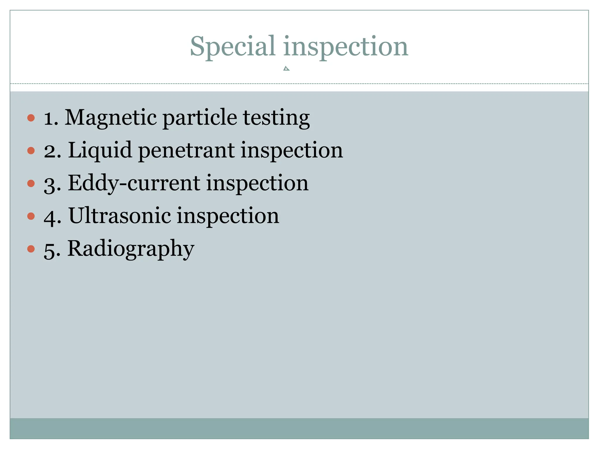
UNIT IV
GENERAL INSPECTION
 INSPECTION
 PROCEDURE
 CHECKLIST
 PUBLICATIONS
 SPECIAL INSPECTIONS
 NDT
 Inspections are visual examinations and manual
checks to determine the condition of an aircraft or
component.
 An aircraft inspection can range from a casual walk
around to a detailed inspection involving complete
disassembly and the use of complex inspection aids.
 An inspection system consists of several processes,
including reports made by mechanics, the pilot, or
crew flying an aircraft and regularly scheduled
inspections of an aircraft.
Basic Inspection
Techniques/Practices
 Before starting an inspection, be certain all plates,
access doors, fairings, and cowling have been opened
or removed and the structure cleaned.
 When opening inspection plates and cowling, and
before cleaning the area, take note of any oil or other
evidence of fluid leakage.
Preparation
 In order to conduct a thorough inspection, a great
deal of paperwork and/or reference information
must be accessed and studied before proceeding to
the aircraft to conduct the inspection.
 The aircraft logbooks must be reviewed to provide
background information and a maintenance history
of the particular aircraft.
 The appropriate checklist or checklists must be
utilized to ensure that no items are forgotten or
overlooked during the inspection.
Checklists
 Always use a checklist when performing an
inspection.
 The checklist may be of your own design, one
provided by the manufacturer of the equipment
being inspected, or one obtained from some other
source.
 The checklist should include the following:
1. Fuselage and Hull Group
 a. Fabric and skin—for deterioration, distortion,
other evidence of failure, and defective or insecure
attachment of fittings.
 b. Systems and components—for proper installation,
apparent defects, and satisfactory operation.
 c. Envelope gas bags, ballast tanks, and related
parts—for condition.
 Cabin and Cockpit Group
 a. General—for cleanliness and loose equipment that needs to
be secured.
 b. Seats and safety belts—for condition and security.
 c. Windows and windshields—for deterioration and breakage.
 d. Instruments—for condition, mounting, marking, and
(where practicable) for proper operation.
 e. Flight and engine controls—for proper installation and
operation.
 f. Batteries—for proper installation and charge.
 g. All systems—for proper installation, general condition,
apparent defects, and security attachment.
Publications
Manufacturers’ Service
Bulletins/Instructions
 Service bulletins or service instructions are two of
several types of publications issued by airframe,
engine, and component manufacturers.
 The bulletins may include:
 purpose for issuing the publication;
 name of the applicable airframe, engine, or
component;
 detailed instructions for service, adjustment,
modification or inspection, and source of parts, if
required;
 estimated number of man-hours required to
accomplish the job.
Maintenance Manual
 The manufacturer’s aircraft maintenance manual
contains complete instructions for maintenance of all
systems and components installed in the aircraft.
 It contains information for the mechanic who
normally works on components, assemblies, and
systems while they are installed in the aircraft, but
not for the overhaul mechanic.
 A typical aircraft maintenance manual contains:
Overhaul Manual
Structural Repair Manual
Illustrated Parts Catalog
Wiring Diagram Manual
Code of Federal Regulations (CFRs)
Airworthiness Directives (ADs)
 A primary safety function of the FAA is to require correction
of unsafe conditions found in an aircraft, aircraft engine,
propeller, or appliance when such conditions exist and are
likely to exist or develop in other products of the same design.
 The unsafe condition may exist because of a design defect,
maintenance, or other causes. Title 14 of the CFR part 39,
Airworthiness Directives, defines the authority and
responsibility of the administrator for requiring the necessary
corrective action.
 The ADs are published to notify aircraft owners and other
interested persons of unsafe conditions and to prescribe the
conditions that the product may continue to be operated.
 Furthermore, these are federal aviation regulations and must
be complied with unless specific exemption is granted.
 There are two categories of ADs:
 Those of an emergency nature requiring immediate
compliance upon receipt.
 Those of a less urgent nature requiring compliance within a
relatively longer period of time.
 Also, ADs may be a one-time compliance item or a recurring
item that requires future inspection on an hourly basis
(accrued flight time since last compliance) or a calendar time
basis.
 The contents of ADs include the aircraft, engine, propeller, or
appliance model and serial numbers affected. Also, included
are the compliance time or period, a description of the
difficulty experienced, and the necessary corrective action.
Type Certificate Data Sheets (TCDS)
 The type certificate data sheet (TCDS) describes
the type design and sets forth the limitations
prescribed by the applicable CFR part.
 It also includes any other limitations and
information found necessary for type
certification of a particular model aircraft.
 All TCDS are numbered in the upper right
corner of each page. This number is the same as
the type certificate number.
 The name of the type certificate holder, together with all
of the approved models, appears immediately below the
type certificate number.
 The issue date completes this group.
 This information is contained within a bordered text box
to set it off.
 The TCDS is separated into one or more sections.
 Each section is identified by a Roman numeral followed
by the model designation of the aircraft that the section
pertains.
 The category or categories that the aircraft can be
certificated in are shown in parentheses following the
model number.
 Also, included is the approval date shown on the type
certificate.
 The data sheet contains information regarding:
 Model designation of all engines that the aircraft
manufacturer obtained approval for use with this
model aircraft.
 Minimum fuel grade to be used.
 Maximum continuous and takeoff ratings of the
approved engines, including manifold pressure
(when used), rotations per minute (rpm), and
horsepower (hp).
 Name of the manufacturer and model designation for
each propeller that the aircraft manufacturer obtained
approval is shown together with the propeller limits and
any operating restrictions peculiar to the propeller or
propeller engine combination.
 Airspeed limits in both miles per hour (mph) and knots.
 Center of gravity (CG) range for the extreme loading
conditions of the aircraft is given in inches from the
datum. The range may also be stated in percent of mean
aerodynamic chord (%MAC) for transport category
aircraft.
 Empty weight center of gravity (EWCG) range (when established) is
given as fore and aft limits in inches from the datum. If no range
exists, the word “none” is shown following the heading on the data
sheet.
 Location of the datum.
 Means provided for leveling the aircraft.
 All pertinent maximum weights.
 Number of seats and their moment arms.
 Oil and fuel capacity.
 Control surface movements.
 Required equipment.
 Additional or special equipment found necessary for certification.
 Information concerning required placards.
Special inspection
 1. Magnetic particle testing
 2. Liquid penetrant inspection
 3. Eddy-current inspection
 4. Ultrasonic inspection
 5. Radiography
NDT
• Nondestructive testing or non-destructive testing
industry to evaluate material, component
the properties of a or s
causing damage.
• The terms nondestructive examination (NDE),
• Because NDT does not permanently alter the artic
NDT does not directly measure mechanical propert
Flaws reduce useful life of component resulting in p
To obtain high level of reliability , defect should be
NDT is carried out periodically.
Replacement of component before its premature fa
Applications of
NDT
• NDT is commonly used in forensic engineering, me
• Innovations in the field of nondestructive
testing have had a profound impact
medical imaging, including
on on
echocardiography, medical ultrasonography, an
Dye Penetrant Inspection
Invisible cracks, porosity and other defects on t
Components may be ferrous, nonferrous, plastic
Procedure:-
1. Cleaning of surface.(Grease, oil, any other m
2.Drying of surface.
3. Applying dye-penetrant on clean and dry surface. It
i) Liquid Soluble Penetrant
ii)Fluroscent
4. Removing excess penetrant by soft or clean cott
5. Applying developer on surface. This pulls out dye
Advantages of Dye Penetrant Inspection
• This test can be applied to almost any type of met
• Simple to utilize and control.
• Results of test can be interpreted fastly.
• Cost of test is very less as it does not require any i
• Sensitivity is greater than that of magnetic particle
Disadvantages of Dye Penetrant Inspection
• Cleaning of components is must before and aft
• Misleading results may be obtained in case of com
• Only surface defects can be detected
• Test is not applicable for powder metallurgical com
Principle-
1.Measure of time required by ultrasonic vibrations to
2.Behaviour of waves through cycle with regard to time
3.By observing this presence of defect and their locatio
Two types of Ultrasonic testing method- i)Pulse –echo
ii) Transmission Method
Ultrasonic Test/inspection
i)Pulse –Echo method:-
ii) Transmission Method:-
Advantages of Ultrasonic Test
• Better detection of flaws situated deep in metal d
• High sensitivity, better accuracy and reliability
• The equipment is portable and easy to handle
• Output of test can be processed by computer whic
Disadvantages of Ultrasonic Test
• Due to manual operation, careful attention an
• Irregularshaped and rough parts are
• Subsurface discontinuities are more difficult to de
• Couplants are needed for testing
4.Magnetic Particle (Magnaflux) Inspection
• It is used to detect various kinds of flaws in
ferromagnetic components such as weldings,
castings, forgings of iron and steel.
• Component to b
e
inspected for flaws
is
magnetized.
• In dry
method
of inspection special
fine
ferromagnetic powder is applied on surface .
• This test is a very fast method of inspection and o
• This test is generally used to detect internal cracks
Magnaflux Test Procedure
1. Cleaning Surface
2. Magnetization
3. Application of ferromagnetic Powder
4. Observation and Inspection
5. Demagnetization
Magnetic Particle /Magnaflux Inspection
Advantages of Magnaflux Test
• Sub-surface cracks can be easily detected
• Almost any shaped and sized component
• Instruments are portable and easy to handle
• Highly sensitive method to detect sm
Disadvantages of Magnaflux Test
• Method is applicable only to ferromagnetic ma
• Surface plating or thin paint coating affect the sen
• After testing, demagnetization is a must
• Local heating and sparking is po
Radiography Test
• NDT method that utilizes x-rays or gamma radia
• This includes X-rays, gamma rays and radio- isoto
• Nowadays, radiography techniques are finding m
• Rays are absorbed by the materials through which
• The cracks, blow holes and cavities appear lighter,
• Developed photographic film show lighter and dar
Advantages of Radiography Test
• X-ray radiography is highly sensitive, fast method o
• X-ray radiography is suitable for various applicatio
• Gamma ray radiography has high penetrating pow
• A number of samples can be inspected at a time b
Disadvantages of Radiography Test
• X-ray radiography can be applied for thinner c
• X-ray radiography allows only one component to be
• X-ray radiography involves high initial cost
• X-ray and gamma ray radiography
• Trained operators are required
Eddy Current Testing
Basic Principle:- When coil carrying alternating curre
Magnitude of induced EMI depend on – i)Magnitud
flowing in coil.
ii)Electrical conductivity of specimen.
iii)Magnetic permeability of specimen.
iv)Shape of specimen.
v) Relative positions of coil and specimen. vi)Microst
Advantages ECT
• Test is quick and less time consuming
• Test can be automated easily
• Permanent record of test results can be easily ava
• Test is versatile and can be used for
Disadvantages of ECT
• The instrument standardization and
calibration is necessary from time to time
• Instruments and display units are costly
• Test can be applied to components of limited size
and shape
Special Inspections
 During the service life of an aircraft, occasions may
arise when something out of the ordinary care and
use of an aircraft could possibly affect its
airworthiness.
 When these situations are encountered, special
inspection procedures, also called conditional
inspections, are followed to determine if damage to
the aircraft structure has occurred.
 Hard or Overweight Landing Inspection
 Severe Turbulence Inspection/Over “G”
 Lightning Strike
 Bird Strike
 Fire Damage
 Flood Damage
 Seaplanes
 Aerial Application Aircraft
Hard or Overweight Landing Inspection
 The structural stress induced by a landing depends not
only upon the gross weight at the time, but also upon the
severity of impact.
 The hard landing inspection is for hard landings at or
below the maximum design landing limits.
 An overweight landing inspection must be performed
when an airplane lands at a weight above the maximum
design landing weight.
 However, because of the difficulty in estimating vertical
velocity at the time of contact, it is hard to judge whether
or not a landing has been sufficiently severe to cause
structural damage.
 For this reason, a special inspection is performed after a
landing is made at a weight known to exceed the design landing
weight or after a rough landing, even though the latter may
have occurred when the aircraft did not exceed the design
landing weight.
 Wrinkled wing skin is the most easily detected sign of an
excessive load having been imposed during a landing.
 Another indication easily detected is fuel leakage along riveted
seams.
 Other possible locations of damage are spar webs, bulkheads,
nacelle skin and attachments, firewall skin, and wing and
fuselage stringers.
 If none of these areas show adverse effects, it is reasonable to
assume that no serious damage has occurred.
 If damage is detected, a more extensive inspection and
alignment check may be necessary.
Severe Turbulence Inspection/Over “G”
 When an aircraft encounters a gust condition, the
airload on the wings exceeds the normal wingload
supporting the aircraft weight.
 The gust tends to accelerate the aircraft while its
inertia acts to resist this change.
 If the combination of gust velocity and airspeed is
too severe, the induced stress can cause structural
damage.
 A special inspection is performed after a flight
through severe turbulence.
 Emphasis is placed upon inspecting the upper and
lower wing surfaces for excessive buckles or wrinkles
with permanent set.
 Where wrinkles have occurred, remove a few rivets
and examine the rivet shanks to determine if the
rivets have sheared or were highly loaded in shear.
 Through the inspection doors and other accessible
openings, inspect all spar webs from the fuselage to
the tip.
 Check for buckling, wrinkles, and sheared
attachments.
 Inspect for buckling in the area around the nacelles
and in the nacelle skin, particularly at the wing
leading edge.
 Check for fuel leaks. Any sizeable fuel leak is an
indication that an area may have received overloads
that have broken the sealant and opened the seams.
Lightning Strike
 Although lightning strikes to aircraft are extremely rare,
if a strike has occurred, the aircraft is carefully inspected
to determine the extent of any damage that might have
occurred.
 When lightning strikes an aircraft, the electrical current
must be conducted through the structure and be allowed
to discharge or dissipate at controlled locations.
 These controlled locations are primarily the aircraft’s
static discharge wicks, or on more sophisticated aircraft,
null field dischargers.
 When surges of high-voltage electricity pass through
good electrical conductors, such as aluminum or steel,
damage is likely to be minimal or nonexistent. When
surges of high-voltage electricity pass through non-
metallic structures, such as a fiberglass radome, engine
cowl or fairing, glass or plastic window, or a composite
structure that does not have built-in electrical bonding,
burning and more serious damage to the structure could
occur.
 Visual inspection of the structure is required. Look for
evidence of degradation, burning, or erosion of the
composite resin at all affected structures, electrical
bonding straps, static discharge wicks, and null field
dischargers.
Bird Strike
 When the aircraft is hit by birds during flight, the
external areas of the airplane are inspected in the
general area of the bird strike.
 If the initial inspection shows structural damage,
then the internal structure of the airplane must be
inspected as well.
 Also, inspect the hydraulic, pneumatic, and any other
systems in the area of the bird strike.
Fire Damage
 Inspection of aircraft structures that have been subjected
to fire or intense heat can be relatively simple if visible
damage is present.
 Visible damage requires repair or replacement. If there is
no visible damage, the structural integrity of an aircraft
may still have been compromised.
 Since most structural metallic components of an aircraft
have undergone some sort of heat treatment process
during manufacture, an exposure to high heat not
encountered during normal operations could severely
degrade the design strength of the structure.
 The strength and airworthiness of an aluminum
structure that passes a visual inspection, but is still
suspect, can be further determined by use of a
conductivity tester.
 This is a device that uses eddy current and is
discussed later in this chapter.
 Since strength of metals is related to hardness,
possible damage to steel structures might be
determined by use of a hardness tester, such as a
Rockwell C hardness tester.
Flood Damage
 Like aircraft damaged by fire, aircraft damaged by
water can range from minor to severe.
 This depends on the level of the flood water, whether
it was fresh or salt water, and the elapsed time
between the flood occurrence and when repairs were
initiated.
 Any parts that were totally submerged are
completely disassembled, thoroughly cleaned, dried,
and treated with a corrosion inhibitor.
 Many parts might have to be replaced, particularly
interior carpeting, seats, side panels, and
instruments.
 Since water serves as an electrolyte that promotes
corrosion, all traces of water and salt must be
removed before the aircraft can again be considered
airworthy.
Seaplanes
 Because they operate in an environment that accelerates
corrosion, seaplanes must be carefully inspected for
corrosion and conditions that promote corrosion.
 Inspect bilge areas for waste hydraulic fluids, water, dirt,
drill chips, and other debris.
 Additionally, since seaplanes often encounter excessive
stress from the pounding of rough water at high speeds,
inspect for loose rivets and other fasteners; stretched,
bent or cracked skins; damage to the float attach fitting;
and general wear and tear on the entire structure.
Aerial Application Aircraft
 Two primary factors that make inspecting these aircraft
different from other aircraft are the corrosive nature of
some of the chemicals used and the typical flight profile.
 Damaging effects of corrosion may be detected in a
much shorter period of time than normal use aircraft.
Chemicals may soften the fabric or loosen the fabric
tapes of fabric-covered aircraft.
 Metal aircraft may need to have the paint stripped,
cleaned, and repainted and corrosion treated annually.
 Leading edges of wings and other areas may require
protective coatings or tapes.
 Hardware may require more frequent replacement.
 During peak use, these aircraft may fly up to 50
cycles (takeoffs and landings) or more in a day, most
likely from an unimproved or grass runway.
 This can greatly accelerate the failure of normal
fatigue items.
 Landing gear and related items require frequent
inspections.
 Because these aircraft operate almost continuously at
very low altitudes, air filters tend to become
obstructed more rapidly.
ATA iSpec 2200
 In an effort to standardize the format in which
maintenance information is presented in aircraft
maintenance manuals, Airlines for America (formerly
Air Transport Association) issued specifications for
Manufacturers Technical Data.
 The original specification was called ATA Spec 100.
 Over the years, Spec 100 has been continuously
revised and updated.
 Eventually, ATA Spec 2100 was developed for
electronic documentation. These two specifications
evolved into one document called ATA iSpec 2200.
 As a result of this standardization, maintenance
technicians can always find information regarding a
particular system in the same section of an aircraft
maintenance manual, regardless of manufacturer.
 The A4A iSPec 2200 divides the aircraft into
systems, such as air conditioning, that covers the
basic air conditioning system (A4A 21). Numbering
in each major system provides an arrangement for
breaking the system down into several subsystems.
12/11/21
Documentation Standard
 ATA Spec 100
 Air Transport Association of America (ATA)
standardized the overall format of the maintenance
manuals
 Each system or system type was assigned a chapter
number. For example,
- Hydraulic systems are in ATA Chapter 29
- Radio equipment is ATA Chapter 23.
12/11/21
Documentation Standard ATA
Format
• 52 11 02 401
Example:
 52 Doors
 52-11 Passenger Doors
 52-11-02 Passenger Door Handle
 52-11-02-401 R/l Procedure for Pax Door Handles
12/11/21
ATA Spec 100
XX-XX-XX-XXX
Page Block
Subject
Section
Chapter
 AIRFRAME GENERAL
05 TIME LIMITS MAINTENANCE CHECKS
06 DIMENSIONS and AREAS
07 LIFTING and SHORING
08 LEVELING and WEIGHTING
09 TOWING and TAXIING
10 PARKING and MOORING
11 PLACARDS
12 SERVICING
 AIRFRAME SYSTEMS
20 STANDARD PRACTICES AIRFRAME
21 AIR CONDITIONING
22 AUTOPILOT
23 COMMUNICATIONS
24 ELECTRIC POWER
25 EQUIPMENT and FURNISHINGS
26 FIRE PROTECTION
27 FLIGHT CONTROLS
28 FUEL
29 HYDRAULIC POWER
30 ICE and RAIN PROTECTION
31 INSTRUMENTS
32 LANDING GEAR
33 LIGHTS
34 NAVIGATION
35 OXYGEN
36 PNEUMATIC
37 VACUUM
38 WATER / WASTE
49 AIRBORNE AUXILIARY POWER
 GROUP STRUCTURE
51 STRUCTURES
52 DOORS
53 FUSELAGE
54 NACELLES / PYLONS
55 STABILIZERS
56 WINDOWS
57 WINGS
 GROUP PROPELLER / ROTOR
60 STD.PRACTICES - PROP / ROTOR
61 PROPELLERS
 GROUP POWER PLANT
70 STANDARD PRACTICES ENGINE
71 POWER PLANT - GENERAL
72 ENGINE
73 ENGINE FUEL and CONTROL
74 IGNITION
75 AIR
76 ENGINE CONTROLS
77 ENGINE INDICATING
78 EXHAUST
79 OIL
80 STARTING
81 TURBINES
82 WATER INJECTION
83 ACCESSORY GEAR BOXES
91 CHARTS
12/11/21
ATA Specification 100
12/11/21
95
ATA Spec 100
UNIT- V
AIRCRAFT HARDWARE,MATERIALS AND SYSTEM
PROCESSES
HAND TOOLS
 General Purpose Tools
 Metal Cutting Tools
 Layout and Measuring Tools
General Purpose Tools
 Hammers and Mallets
 Screwdrivers
 Pliers and Plier-Type Cutting Tools
 Punches
 Wrenches
 Special Wrenches
 Torque Wrench
 Strap Wrenches
 Impact Drivers
Metal Cutting Tools
 Hand Snips
 Hacksaws
 Chisels
 Files
 Drills
 Twist Drills
 Reamers
 Countersink
 Taps and Die
Layout and Measuring Tools
 Rules
 Combination Sets
 Scriber
 Dividers and Pencil Compasses
 Calipers
 Micrometer Calipers
 Vernier Scale
 Slide Calipers
Hammers and Mallets
 some of the hammers that the aviation mechanic may be required to use.
 Metal head hammers are usually sized according to the weight of the
head alone without the handle.
 Occasionally, it is necessary to use a soft-faced hammer, which has a
striking surface made of wood, brass, lead, rawhide, hard rubber, or
plastic.
 These hammers are intended for use in forming soft metals and striking
surfaces that are easily damaged.
 Soft-faced hammers should not be used for striking punch heads, bolts,
or nails, as using one in this fashion quickly ruins this type of hammer.
 A mallet is a hammer-like tool with a head made of hickory, rawhide, or
rubber.
 It is handy for shaping thin metal parts without causing creases or dents
with abrupt corners.
 Always use a wooden mallet when pounding a wood chisel or a gouge.
 When using a hammer or mallet, choose the one best
suited for the job. Ensure that the handle is tight.
 When striking a blow with the hammer, use the forearm
as an extension of the handle. Swing the hammer by
bending the elbow, not the wrist. Always strike the work
squarely with the full face of the hammer.
 When striking a metal tool with a metal hammer, the use
of safety glasses or goggles is strongly encouraged.
 Always keep the faces of hammers and mallets smooth
and free from dents, chips, or gouges to prevent marring
of the work.
Screwdrivers
 The screwdriver can be classified by its shape, type of
blade, and blade length.
 It is made for only one purpose, loosening or tightening
screws or screw head bolts.
 When using the common screwdriver, select the largest
screwdriver whose blade makes a good fit in the screw
that needs to be turned.
 A common screwdriver must fill at least 75 percent of the
screw slot.
 If the screwdriver is the wrong size, it cuts and burrs the
screw slot, making it unusable.
 The damage may be so severe that the use of a screw
extractor may be required.
 A screwdriver with the wrong size blade may slip and
damage adjacent parts of the structure as well.
 The common screwdriver is used only where slotted head
screws or fasteners are found on aircraft.
 The two types of recessed head screws for common use
are the Phillips and the Reed & Prince.
 Both the Phillips and Reed & Prince recessed heads are
optional on several types of screws.
Pliers and Plier-Type Cutting Tools
 the pliers used most frequently in aircraft repair work are the
diagonal, needlenose, and duckbill. The size of pliers indicates their
overall length, usually ranging from 5 to 12 inches.
 Roundnose pliers are used to crimp metal.
 They are not made for heavy work because too much pressure springs
the jaws, which are often wrapped to prevent scarring the metal.
 Needlenose pliers have half round jaws of varying lengths.
 They are used to hold objects and make adjustments in tight places.
 Duckbill pliers resemble a “duck’s bill” in that the jaws are thin, flat,
and have the shape of a duck’s bill.
 They are used exclusively for twisting safety wire.
 Diagonal pliers are usually referred to as diagonals or “dikes.”
 The diagonal is a short-jawed cutter with a blade set at a slight angle
on each jaw. This tool can be used to cut wire, rivets, small screws, and
cotter pins, besides being practically indispensable in removing or
installing safety wire. The duckbill pliers and the diagonal cutting
pliers are used extensively in aviation for the job of safety wiring.
 Two important rules for using pliers:
 1. Do not make pliers work beyond their capacity.
The long-nosed variety is especially delicate. It is
easy to spring or break them or nick the edges. If this
occurs, they are practically useless.
 2. Do not use pliers to turn nuts. In just a few
seconds, a pair of pliers can damage a nut more than
years of service.
Wrenches
 The wrenches most often used in aircraft maintenance are
classified as open-end, box-end, socket, adjustable, ratcheting and
special wrenches.
 The Allen wrench, although seldom used, is required on one
special type of recessed screw.
 One of the most widely used metals for making wrenches is
chrome-vanadium steel.
 Wrenches made of this metal are almost indestructible.
 Solid, nonadjustable wrenches with open parallel jaws on one or
both ends are known as open-end wrenches. These wrenches may
have their jaws parallel to the handle or at an angle up to 90°;
most are set at an angle of 15°.
 The wrenches are designed to fit a nut, bolt head, or other object,
which makes it possible to exert a turning action.
 Box-end wrenches are popular tools because of their
usefulness in close quarters.
 They are called box wrenches since they box, or
completely surround, the nut or bolt head.
 A socket wrench is made of two parts: the socket,
which is placed over the top of a nut or bolt head; and
a handle, which is attached to the socket.
 Many types of handles, extensions, and attachments
are available to make it possible to use socket
wrenches in almost any location or position.
 Sockets are made with either fixed or detachable
handles
Special Wrenches
 The category of special wrenches includes the
crowfoot, flare nut, spanner, torque, and Allen
wrenches.
 The crowfoot wrench is normally used when
accessing nuts that must be removed from studs or
bolts that cannot be accessed using other tools.
 The flare nut wrench has the appearance of a box-
end wrench that has been cut open on one end.
Torque Wrench
 There are times when definite pressure must be
applied to a nut or bolt as it is installed.
 In such cases, a torque wrench must be used. The
torque wrench is a precision tool consisting of a
torque indicating handle and appropriate adapter or
attachments.
 It measures the amount of turning or twistingforce
applied to a nut, bolt, or screw.
Strap Wrenches
 The strap wrench can prove to be an invaluable tool for
the AMT.
 By their very nature, aircraft components, such as tubing,
pipes, small fittings, and round or irregularly-shaped
components, are built to be as light as possible while still
retaining enough strength to function properly.
 The misuse of pliers or other gripping tools can quickly
damage these parts.
 If it is necessary to grip a part to hold it in place, or to
rotate it to facilitate removal, consider using a strap
wrench that uses a plastic covered fabric strap to grip the
part.
Impact Drivers
 In certain applications, the use of an impact driver
may be required.
 Struck with a mallet, the impact driver uses cam
action to impart a high amount of torque in a sharp
impact to break loose a stubborn fastener.
 The drive portion of the impact driver can accept a
number of different drive bits and sockets.
 The use of special bits and sockets specifically
manufactured for use with an impact driver is
required.
Metal Cutting Tools
Hand Snips
 There are several kinds of hand snips, each of which
serves a different purpose.
 Straight, curved, hawksbill, and aviation snips are in
common use.
 Straight snips are used for cutting straight lines
when the distance is not great enough to use a
squaring shear and for cutting the outside of a curve.
 The other types are used for cutting the inside of
curves or radii.
 Snips should never be used to cut heavy sheet metal.
Hacksaws
 The common hacksaw has a blade, a frame, and a
handle.
 The handle can be obtained in two styles: pistol grip
and straight.
 Hacksaw blades have holes in both ends; they are
mounted on pins attached to the frame.
 When installing a blade in a hacksaw frame, mount
the blade with the teeth pointing forward, away from
the handle.
Chisels
 A chisel is a hard steel cutting tool that can be used
for cutting and chipping any metal softer than the
chisel itself.
 It can be used in restricted areas and for such work
as shearing rivets, or splitting seized or damaged
nuts from bolts.
 The size of a flat cold chisel is determined by the
width of the cutting edge.
 Lengths vary, but chisels are seldom under 5 inches
or over 8 inches long.
 Chisels are usually made of eight-sided tool steel bar
stock, carefully hardened and tempered.
 Since the cutting edge is slightly convex, the center
portion receives the greatest shock when cutting, and
the weaker corners are protected.
 The cutting angle should be 60° to 70° for general
use, such as for cutting wire, strap iron, or small bars
and rods.
Files
 Most files are made of high-grade tool steels that are
hardened and tempered.
 Files are manufactured in a variety of shapes and sizes.
 They are known either by the cross section, the general
shape, or by their particular use.
 The cuts of files must be considered when selecting them
for various types of work and materials.
 Files are used to square ends, file rounded corners, remove
burrs and slivers from metal, straighten uneven edges,
smooth rough edges, and file holes and slots.
 Files are usually made in two types of cuts: single cut and
double cut.
 The single cut file has a single row of teeth extending
across the face at an angle of 65° to 85° with the length
of the file.
 The size of the cuts depends on the coarseness of the file.
The double cut file has two rows of teeth that cross each
other.
 For general work, the angle of the first row is 40° to 45°.
The first row is generally referred to as “overcut,” and
the second row as “upcut;” the upcut is somewhat finer
than and not as deep as the overcut.
Drills
 The four types of portable drills used in aviation for
holding and turning twist drills are the hand drill,
breast drill, electric power drill, and pneumatic
power drill.
 Holes 1⁄4 inch in diameter and under can be drilled
using a hand drill. This drill is commonly called an
“egg beater.”
 The breast drill is designed to hold larger size twist
drills than the hand drill.
 Also, a breastplate is affixed at the upper end of the
drill to permit the use of body weight to increase the
cutting power of the drill.
 Electric and pneumatic power drills are available in
various shapes and sizes to satisfy almost any
requirement.
 Pneumatic drills are preferred for use around
flammable materials, since sparks from an electric
drill are a fire or explosion hazard.
Reamers
 Reamers are used to smooth and enlarge holes to exact size.
 Hand reamers have square end shanks so that they can be turned
with a tap wrench or similar handle.
 A hole that is to be reamed to exact size must be drilled about
0.003 to 0.007 inch undersize.
 A cut that removes more than 0.007 inch places too much load on
the reamer and should not be attempted.
 Reamers are made of either carbon tool steel or high-speed steel.
 The cutting blades of a high-speed steel reamer lose their original
keenness sooner than those of a carbon steel reamer; however,
after the first super keenness is gone, they are still serviceable.
 The high-speed reamer usually lasts much longer than the carbon
steel type.
Countersink
 A countersink is a tool that cuts a cone-shaped depression
around the hole to allow a rivet or screw to set flush with the
surface of the material.
 Countersinks are made with various angles to correspond to the
various angles of the countersunk rivet and screw heads.
 Special stop countersinks are available.
 Stop countersinks are adjustable to any desired depth, and the
cutters are interchangeable so that holes of various countersunk
angles may be made.
 Some stop countersinks have a micrometer set arrangement (in
increments of 0.001 inch) for adjusting the cutting depths
 When using a countersink, care must be taken not to remove an
excessive amount of material, since this reduces the strength of
flush joints.
Taps and Dies
 A tap is used to cut threads on the inside of a hole, while
a die is for cutting external threads on round stock.
 They are made of hard tempered steel and ground to an
exact size.
 There are four types of threads that can be cut with
standard taps and dies: National Coarse, National Fine,
National Extra Fine, and National Pipe.
 Hand taps are usually provided in sets of three taps for
each diameter and thread series.
 Each set contains a taper tap, a plug tap, and a bottoming
tap.
 The taps in a set are identical in diameter and cross
section and the only difference is the amount of taper.
Layout and Measuring Tools
 Layout and measuring devices are precision tools.
 They are carefully machined, accurately marked and,
in many cases, are made up of very delicate parts.
 When using these tools, be careful not to drop, bend,
or scratch them.
 The finished product is no more accurate than the
measurements or the layout; therefore, it is very
important to understand how to read, use, and care
for these tools.
 Rules
 Combination Sets
 Scriber
 Dividers and Pencil Compasses
 Calipers
 Micrometer Calipers
 Vernier Scale
 Slide Calipers
Rules
 Rules are made of steel and are either rigid or flexible.
 The flexible steel rule bends, but it should not be bent
intentionally as it may be broken rather easily.
 In aircraft work, the unit of measure most commonly
used is the inch.
 The inch may be divided into smaller parts by means of
either common or decimal fraction divisions.
 The fractional divisions for an inch are found by
dividing the inch into equal parts: halves (1⁄2), quarters
(1⁄4), eighths (1⁄8), sixteenths (1⁄16), thirty-secondths
(1⁄32), and sixty-fourths (1⁄64).
 The fractions of an inch may be expressed in
decimals, called decimal equivalents of an inch.
 Rules are manufactured in two basic styles — those
divided or marked in common fractions and those
divided or marked in decimals or divisions of one
one-hundredth of an inch.
 A rule may be used either as a measuring tool or as a
straightedge.
Combination Sets
 The combination set, as its name implies, is a tool
that has several uses.
 It can be used for the same purposes as an ordinary
tri-square, but it differs from the tri-square in that
the head slides along the blade and can be clamped
at any desired place.
 Combined with the square or stock head are a level
and scriber.
 The head slides in a central groove on the blade or
scale, which can be used separately as a rule.
 The spirit level in the stock head makes it convenient to
square a piece of material with a surface and at the same
time tell whether one or the other is plumb or level.
 The head can be used alone as a simple level.
 The combination of square head and blade can also be
used as a marking gauge to scribe lines at a 45° angle, as a
depth gauge, or as a height gauge.
 A convenient scriber is held frictionally in the head by a
small brass bushing.
 The center head is used to find the center of shafts or
other cylindrical work.
 The protractor head can be used to check angles and also
may be set at any desired angle to draw lines.
Scriber
 The scriber is designed to serve the aviation mechanic
in the same way a pencil or pen serves a writer.
 In general, it is used to scribe or mark lines on metal
surfaces.
 The scriber is made of tool steel, 4 to 12 inches long,
and has two needle pointed ends. One end is bent at a
90° angle for reaching and marking through holes.
 Before using a scriber, always inspect the points for
sharpness. Be sure the straightedge is flat on the metal
and in position for scribing.
 Tilt the scriber slightly in the direction toward which
it will be moved, holding it like a pencil.
 Keep the scriber’s point close to the guiding edge of
the straightedge.
 The scribed line should be heavy enough to be
visible, but no deeper than necessary to serve its
purpose.
 It is very important to use a scribe only where it is
defining a line to be cut as scribed lines may
introduce stress points where failures can occur.
Dividers and Pencil Compasses
 Dividers and pencil compasses have two legs joined
at the top by a pivot.
 They are used to scribe circles and arcs and for
transferring measurements from the rule to the
work.
 Pencil compasses have one leg tapered to a needle
point.
 The other leg has a pencil or pencil lead inserted.
 Dividers have both legs tapered to needle points.
Calipers
 Calipers are used for measuring diameters and distances or
for comparing distances and sizes.
 The three common types of calipers are inside, outside, and
hermaphrodite calipers, such as gear tool calipers.
 Outside calipers are used for measuring outside dimensions—
for example, the diameter of a piece of round stock.
 Inside calipers have outward curved legs for measuring inside
diameters, such as diameters of holes, the distance between
two surfaces, the width of slots, and other similar jobs.
 A hermaphrodite caliper is generally used as a marking gauge
in layout work. It should not be used for precision
measurement.
Micrometer Calipers
 There are four types of micrometer calipers, each
designed for a specific use: outside micrometer,
inside micrometer, depth micrometer, and thread
micrometer.
 Micrometers are available in a variety of sizes, either
0 to 1⁄2 inch, 0 to 1 inch, 1 to 2 inch, 2 to 3 inch, 3 to 4
inch, 4 to 5 inch, or 5 to 6 inch sizes.
 In addition to the micrometer inscribed with the
measurement markings, micrometers equipped with
electronic digital liquid crystal display (LCD)
readouts are also in common use.
Micrometer Parts
 The fixed parts of a micrometer are the frame, barrel,
and anvil.
 The movable parts of a micrometer are the thimble and
spindle.
 The thimble rotates the spindle, which moves in the
threaded portion inside the barrel.
 Turning the thimble provides an opening between the
anvil and the end of the spindle where the work is
measured.
 The size of the work is indicated by the graduations on
the barrel and thimble.
Vernier Scale
 Some micrometers are equipped with a vernier scale
that makes it possible to directly read the fraction of
a division that is indicated on the thimble scale.
Slide Calipers
 Often used to measure the length of an object, the
slide caliper provides greater accuracy than the ruler.
 It can, by virtue of its specially formed jaws, measure
both inside and outside dimensions.
 As the tool’s name implies, the slide caliper jaw is
slide along a graduated scale, and its jaws then
contact the inside or outside of the object to be
measured.
 The measurement is then read on the scale located
on the body of the caliper or on the LCD screen.
Fluid Lines and
Fittings
 Aircraft fluid lines are usually made of metal tubing
or flexible hose.
 Metal tubing (also called rigid fluid lines) is used in
stationary applications and where long, relatively
straight runs are possible.
 They are widely used in aircraft for fuel, oil, coolant,
oxygen, instrument, and hydraulic lines.
 Flexible hose is generally used with moving parts or
where the hose is subject to considerable vibration.
Rigid Fluid Lines
Tubing Materials
 Copper
 Aluminum Alloy Tubing
 Steel
 Titanium
 Copper
 In the early days of aviation, copper tubing was used
extensively in aviation fluid applications. In modern
aircraft, aluminum alloy, corrosion-resistant steel, or
titanium tubing have generally replaced copper
tubing.
 Aluminum Alloy Tubing
 Tubing made from 1100 H14 (1⁄2-hard) or 3003 H14
(1⁄2-hard) is used for general purpose lines of low or
negligible fluid pressures, such as instrument lines
and ventilating conduits.
 Tubing made from 2024-T3, 5052-O, and 6061-T6
aluminum alloy materials is used in general purpose
systems of low and medium pressures, such as
hydraulic and pneumatic 1,000 to 1,500 psi systems,
and fuel and oil lines
 Steel
 Corrosion-resistant steel tubing, either annealed CRES 304,
CRES 321, or CRES 304-1⁄8-hard, is used extensively in high-
pressure hydraulic systems (3,000 psi or more) for the
operation of landing gear, flaps, brakes, and in fire zones. Its
higher tensile strength permits the use of tubing with thinner
walls; consequently, the final installation weight is not much
greater than that of the thicker wall aluminum alloy tubing.
 Steel lines are used where there is a risk of foreign object
damage (FOD) (i.e., the landing gear and wheel well areas).
Swaged or MS flareless fittings are used with corrosion-
resistant tubing. Although identification markings for steel
tubing differ, each usually includes the manufacturer’s name or
trademark, the Society of Automotive Engineers (SAE)
number, and the physical condition of the metal.
 Titanium 3AL–2.5V
 Titanium 3AL–2.5V tubing and fitting is used extensively
in transport category and high-performance aircraft
hydraulic systems for pressures above 1,500 psi.
Titanium is 30 percent stronger than steel and 50
percent lighter than steel.
 Cryofit fittings or swaged fittings are used with titanium
tubing. Do not use titanium tubing and fittings in any
oxygen system assembly. Titanium and titanium alloys
are oxygen reactive. If a freshly formed titanium surface
is exposed in gaseous oxygen, spontaneous combustion
could occur at low pressures.
FUEL LINE IDENTIFICATION
AN standard fittings
Flexible Hose Fluid Lines
 Flexible hose is used in aircraft fluid systems to
connect moving parts with stationary parts in
locations subject to vibration or where a great
amount of flexibility is needed.
 It can also serve as a connector in metal tubing
systems.
Hose Materials and Construction
 Pure rubber is never used in the construction of
flexible fluid lines.
 To meet the requirements of strength, durability, and
workability, among other factors, synthetics are used
in place of pure rubber.
 Synthetic materials most commonly used in the
manufacture of flexible hose are Buna-N, neoprene,
butyl, ethylene propylene diene rubber (EPDM) and
Teflon™.
 While Teflon™ is in a category of its own, the others
are synthetic rubber.
Types of materials used
Buna-N
 Buna-N is a synthetic rubber compound that has excellent
resistance to petroleum products.
 Do not use for phosphate ester base hydraulic fluid (Skydrol™).
Neoprene
 Neoprene is a synthetic rubber compound that has an acetylene
base.
 Its resistance to petroleum products is not as good as Buna-N, but it
has better abrasive resistance.
 Do not use for phosphate ester base hydraulic fluid (Skydrol™).
 Butyl
 Butyl is a synthetic rubber compound made from petroleum raw
materials.
 It is an excellent material to use with phosphate ester base hydraulic
fluid (Skydrol™).
 Do not use with petroleum products.
 Flexible rubber hose consists of a seamless
synthetic rubber inner tube covered with layers of
cotton braid and wire braid and an outer layer of
rubber-impregnated cotton braid.
 This type of hose is suitable for use in fuel, oil,
coolant, and hydraulic systems.
 The types of hose are normally classified by the
amount of pressure they are designed to withstand
under normal operating conditions: low, medium,
and high.
 Low pressure—below 250 psi. Fabric braid
reinforcement.
 Medium pressure—up to 3,000 psi. One wire braid
reinforcement. Smaller sizes carry up to 3,000 psi.
Larger sizes carry pressure up to 1,500 psi.
 High pressure—all sizes up to 3,000 psi operating
pressures.
 Flexible hoses used for brake systems have
sometimes a stainless steel wire braid installed over
the hose to protect the hose from damage
 Teflon™ is the DuPont trade name for
tetrafluoroethylene resin.
 It has a broad operating temperature range (−65 °F
to+450 °F). It is compatible with nearly every substance
or agent used. It offers little resistance to flow; sticky,
viscous materials do not adhere to it.
 It has less volumetric expansion than rubber, and the
shelf and service life is practically limitless.
 Teflon™ hose is flexible and designed to meet the
requirements of higher operating temperatures and
pressures in present aircraft systems.
 Generally, it may be used in the same manner as rubber
hose.
 Teflon™ hose is processed and extruded into tube
shape to a desired size.
 It is covered with stainless steel wire, which is
braided over the tube for strength
 and protection.
 Teflon™ hose is unaffected by any known fuel,
petroleum, or synthetic base oils, alcohol, coolants,
or solvents commonly used in aircraft.
 Teflon™ hose has the distinct advantages of a
practically unlimited storage time, greater operating
temperature range, and broad usage
 Hose Identification
 Lay lines and identification markings consisting of
lines, letters, and numbers are printed on the hose.
 Most hydraulic hose is marked to identify its type,
the quarter and year of manufacture, and a 5-digit
code identifying the manufacturer.
 These markings are in contrasting colored letters
and numerals that indicate the natural lay (no
twist) of the hose and are repeated at intervals of
not more than 9 inches along the length of the
hose.
 Code markings assist in replacing a hose with one
of the same specifications or a recommended
substitute.
 Hose suitable for use with phosphate ester base
hydraulic fluid is marked Skydrol™ use.
 In some instances, several types of hose may be
suitable for the same use.
 Therefore, to make the correct hose selection,
always refer to the applicable aircraft maintenance
or parts manual.
Aircraft Hardware
 Aircraft hardware is the term used to describe the
various types of fasteners and miscellaneous small
items used in the manufacture and repair of aircraft.
 The importance of aircraft hardware is often
overlooked because of its small size; however, the
safe and efficient operation of any aircraft is greatly
dependent upon the correct selection and use of
aircraft hardware
Identification
 Their specification number or trade name identifies
most items of aircraft hardware.
 Threaded fasteners and rivets are identified by AN
(Air Force-Navy) numbers, NAS (National Aircraft
Standard) numbers, or MS (Military Standard)
numbers.
 Quick-release fasteners are usually identified by
factory trade names and size designations.
Classification of Threads
 Aircraft bolts, screws, and nuts are threaded in the
American National Coarse (NC) thread series, the
American National Fine (NF) thread series, the
American Standard Unified Coarse (UNC) thread
series, or the American Standard Unified Fine (UNF)
thread series.
 There is one difference between the American
National series and the American Standard Unified
series that should be pointed out.
 In the 1-inch diameter size, the NF thread specifies
14 threads per inch (1-14 NF), while the UNF thread
specifies 12 threads per inch (1-12 UNF)
 Class of fit also designates threads.
 The Class of a thread indicates the tolerance allowed
in manufacturing:
 Class 1 is a loose fit
 Class 2 is a free fit
 Class 3 is a medium fit
 Class 4 is a close fit
 Aircraft bolts are almost always manufactured in the
Class 3, medium fit.
Aircraft Bolts
 Aircraft bolts are fabricated from cadmium- or zinc-
plated corrosion-resistant steel, un-plated corrosion-
resistant steel, or anodized-aluminum alloys.
 Most bolts used in aircraft structures are either general
purpose, AN bolts, NAS internal wrenching or close
tolerance bolts, or MS bolts.
 In certain cases, aircraft manufacturers make bolts of
different dimensions or greater strength than the
standard types.
 Such bolts are made for a particular application, and it is
of extreme importance to use like bolts in replacement.
 The letter “S” stamped on the head usually identifies
special bolts.
 AN bolts come in three head styles: hex head, Clevis,
and eyebolt.
 NAS bolts are available in hex head, internal
wrenching, and countersunk head styles.
 MS bolts come in hex head and internal wrenching
styles.
Special-Purpose Bolts
 Bolts designed for a particular application or use is
classified as special-purpose bolts.
 Clevis bolts,
 eyebolts,
 Jo-bolts,
 lockbolts
Aircraft Nuts
 Aircraft nuts are made in a variety of shapes and
sizes.
 They are made of cadmium-plated carbon steel,
stainless steel, or anodized 2024T aluminum alloy
and may be obtained with either right- or left-hand
threads.
 No identifying marking or lettering appears on nuts
 Aircraft nuts can be divided into two general groups:
non-self-locking and self-locking nuts.
 Non-self-locking nuts are those that must be safe
tied by external locking devices, such as cotter pins,
safety wire, or locknuts.
 Self-locking nuts contain the locking feature as an
integral part.
Non-Self-Locking Nuts
 Most of the familiar types of nuts, including the plain
nut, the castle nut, the castellated shear nut, the
plain hex nut, the light hex nut, and the plain check
nut are the non-self-locking type.
Self-Locking Nuts
 As their name implies, self-locking nuts need no auxiliary
means of safetying but have a safetying feature included
as an integral part of their construction.
 Many types of self locking nuts have been designed and
their use has become quite widespread.
 Common applications are:
 • Attachment of antifriction bearings and control pulleys
 • Attachment of accessories, anchor nuts aroun
inspection holes, and small tank installation openings
 • Attachment of rocker box covers and exhaust stacks
Aircraft Washers
 Aircraft washers used in airframe repair are either
plain, lock, or special type washers.
Plain Washers
 Plain washers, both the AN960 and AN970, are used
under hex nuts.
 They provide a smooth bearing surface and act as a
shim in obtaining correct grip length for a bolt and
nut assembly.
 They are used to adjust the position of castellated
nuts in respect to drilled cotter pin holes in bolts.
 Use plain washers under lock washers to prevent
damage to the surface material.
Lock Washers
 Lock washers, both the AN935 and AN936, are used with machine
screws or bolts where the self-locking or castellated-type nut is not
appropriate.
 The spring action of the washer (AN935) provides enough friction to
prevent loosening of the nut from vibration.
 Lock washers should never be used under the following conditions:
 With fasteners to primary or secondary structures
 With fasteners on any part of the aircraft where failure might result in
damage or danger to the aircraft or personnel
 Where failure would permit the opening of a joint to the airflow
 Where the screw is subject to frequent removal
 Where the washers are exposed to the airflow
 Where the washers are subject to corrosive conditions
 Where the washer is against soft material without a plain washer
underneath to prevent gouging the surface
Special Washers
 The ball socket and seat washers, AC950 and AC955, are
special washers used where a bolt is installed at an angle
to a surface or where perfect alignment with a surface is
required. These washers are used together
 The NAS143 and MS20002 washers are used for internal
wrenching bolts of the NAS144 through NAS158 series.
This washer is either plain or countersunk.
 The countersunk washer (designated as NAS143C and
MS20002C) is used to seat the bolt head shank radius,
and the plain washer is used under the nut.
Aircraft Rivets
 Sheets of metal must be fastened together to form
the aircraft structure, and this is usually done with
solid aluminum-alloy rivets.
 A rivet is a metal pin with a formed head on one
end when the rivet is manufactured.
 The shank of the rivet is inserted into a drilled
hole, and its shank is then upset (deformed) by a
hand or pneumatic tool.
 The second head, formed either by hand or by
pneumatic equipment, is called a “shop head.” The
shop head functions in the same manner as a nut
 In addition to their use for joining aircraft skin
sections, rivets are also used for joining spar sections,
for holding rib sections in place, for securing fittings to
various parts of the aircraft, and for fastening
innumerable bracing members and other parts
together.
 The rivet creates a bond that is at least as strong as the
material being joined.
 Two of the major types of rivets used in aircraft are the
common solid shank type, which must be driven using
a bucking bar, and the special (blind) rivets, which may
be installed where it is impossible to use a bucking bar.
Solid Shank Rivets
 Solid shank rivets are generally used in repair work.
 They are identified by the kind of material of which they are
made, their head type, size of shank, and their temper condition.
 The designation of the solid shank rivet head type, such as
universal head, roundhead, flathead, countersunk head, and
brazier head, depends on the cross-sectional shape of the head.
 The material used for most aircraft solid shank rivets is
aluminum alloy.
 The strength and temper conditions of aluminum-alloy rivets are
identified by digits and letters similar to those adopted for the
identification of strength and temper conditions of aluminum
and aluminum-alloy stock.
 The 1100, 2017-T, 2024-T, 2117-T, and 5056 rivets are the five
grades usually available.
Blind Rivets
 There are many places on an aircraft where access to
both sides of a riveted structure or structural part is
impossible, or where limited space does not permit
the use of a bucking bar.
 Also, in the attachment of many nonstructural parts,
such as aircraft interior furnishings, flooring, deicing
boots, and the like, the full strength of solid shank
rivets is not necessary.
Mechanically-Expanded Rivets
 Two classes of mechanically-expanded rivets
 • Nonstructural—self-plugging (friction lock) rivets,
pull-thru rivets
 • Mechanical lock—flush fracturing, self-plugging
rivets
Pull-Thru Rivets
 Several companies manufacture the pull-thru blind
rivets.
 The same general basic information about their
fabrication, composition, uses, selection, installation,
inspection, and removal procedures apply to all of
them.
 Pull-thru rivets are fabricated in two parts: a rivet
head with a hollow shank or sleeve and a stem that
extends through the hollow shank.
Bearing
A bearing is any surface that supports
or is supported by another surface.
It is a part in which a journal, pivot,
pin, shaft, or similar device turns or
revolves.
The bearings used in aircraft engines
are designed to produce minimum
friction and maximum wear resistance.
 A good bearing has two broad
characteristics:
1)it must be made of a material that is strong
enough to withstand the pressure imposed
on it and yet permit the other surface to
move with a minimum of wear and friction
2)the parts must be held in position within
very close tolerances to provide quiet and
efficient operation and at the same time
permit freedom of motion.
Plain Bearings
 These bearings are usually designed to take radial loads;
however, plain bearings with flanges are often used as thrust
bearings in opposed aircraft engines.
 Plain bearings are used for connecting rods,crankshafts, and
camshafts of low-power aircraft engines.
 The metal used for plain bearings may be silver, lead, an alloy
(such as bronze or babbitt), or a combination of metals.
 Bronze withstands high compressive pressures but offers
more friction than babbitt.
 Conversely, babbitt, a soft bearing alloy, silver in color and
composed of tin, copper, and antimony, offers less friction but
cannot withstand high compressive pressures as well as
bronze.
Roller Bearings
 The roller bearings are one of the two types known as
"antifriction" bearings because the rollers eliminate friction to
a large extent.
 These bearings are made in a variety of shapes and sizes and
can be adapted to both radial and thrust loads.
 Straight roller bearings are generally used only for radial
loads; however, tapered roller bearings will support both
radial and thrust loads.
 The bearing race is the guide or channel along which the
rollers travel.
 In a roller bearing, the roller is situated between an inner and
an outer race, both of which are made of case-hardened steel.
 When a roller is tapered, it rolls on a cone-shaped race inside
an outer race.
Ball Bearings
 Ball bearings provide less rolling friction than any
other type.
 A ball bearing consists of an inner race and an outer
race, a set of polished steel balls, and a ball retainer.
 Some ball bearings are made with two rows of balls
and two sets of races.
 The races are designed with grooves to fit the
curvature of the balls in order to provide a large
contact surface for carrying high radial loads.
3
Types of Gear
The gear has been classified through a lot of methods. The classification that is most popular is through the different position of the gear axis. Another way is through method of
Classifications by the position of gear axis
(1) Parallel axis gear (The teeth are parallel to axis)
a) Spur gear
This is Cylindrical gear. Tooth trace is parallel to axis. This is a highly demanded gear, which is easy to man- ufacture and to assemble.
b) Helical gear
This is a Cylindrical gear. Tooth trace has helix curve. Helical gear provides more strength, less oscillation and lower noise level compared with Spur gears. However H
c) Internal gear
This is a cylindrical gear ring with teeth formed at the inner diameter. The most popular demand for Internal gears is used for mechanism of planetary gear train. Ther
d) Straight Rack
It is thought that radius of spur gear grew infinite to become a straight line. It can be matched with Spur gear to convert between the rectilinear motion and the rotary
e) Helical Rack
It is thought that radius of Helical gear grew infinite to become a straight line and Tooth trace is also straight line. It can be matched with Helical gear to convert betw
Spur gear
Helical gear
Internal gear
Straight Rack
Helical Rack
4
f) Double helical gear
The shape looks like two Helical gear joined together. Therefore this type of gear does not have thrust load to axis during operation.
Other types of gear designs used for parallel axis such as non-circular gear and Eccentricity gear are available but omitted this time.
(2) Intersecting axis gear
g) Straight bevel (Miter) gear
This is gear with Tooth trace, which is a straight line in the same direction as surface element of Pitch cone. Miter gear has shaft angle of 90 and gear ratio of 1:1.
h) Angular straight bevel gear
Angular straight bevel gear which does not have shaft angle of 90.
i) Spiral bevel gear
Tooth trace is described as a curve with spiral angle. Spiral bevel gear has advantage over Straight bevel gear for gear strength, oscillation and noise level. Disadvanta
j) Angular spiral bevel gear
Angular spiral bevel gear does not have shaft angle of 90.
k) Zerol® bevel gear
This is Zerol® bevel gear, similar to Spiral bevel gear with zero spiral angle. The Tooth trace is described as a curve with spiral angle of zero degree. (Occasionally, spi
The force of tooth action is the same as Straight bevel gear.
( Ⓡ mark is Gleason Works trademark)
Double helical gear
Straight bevel (Miter) gear
Angular straight bevel gear
Spiral bevel gear
Angular spiral bevel gear
Zerol® bevel gear
5
l) Face gear
is Face gear. A Toothed disk gear, can be matched with Spur or Helical gear. There are two types of Face gear with shaft angle 90, intersecting axis and Non interse
(3) Skew gear (Non Intersected Gear)
m) Cylindrical worm gear
This is a Worm gear pair consisting of Cylindrical worm gear and Worm wheel.
Meaning of Cylindrical worm gear is that the thread has one or more starts.
This Worm gear pair provides high speed reducing ratio and low noise level. Disadvantages are low ef- ficiency and generation of heat.
n) Crossed helical gear (Screw gear)
This is a Gear pair for transmission between Non- parallel and Non-intersecting axes of Cylindrical gears as pair of Helical or Spur gear. Due to spot contact in theory,
o) Hypoid® gear
This is a gear for transmission between Non-parallel and Non-intersecting axis of conical gear. This gear is similar to Spiral bevel gear. Most popular usage is for Def
( Ⓡ mark is Gleason Works trademark)
Others including Enveloping worm, Spiroid® and Helicon gear types of gear designs are available for Non-parallel and Non-intersecting axis but omitted this time. (
Face gear
Cylindrical worm
Cylindrical worm
Cylindrical worm wheel
Crossed helical gear (Screw gear)
Hypoid® gear
6
(4) Machine elements compared with gear for simi- lar shape and purpose of usage.
p) Sprockets
This is Sprocket wheel used for matching with bushed chain and Ladder chains. Usage is for transmitting a power over long distances between axes.
r) Ratchet gear
This is Ratchet gear, which looks like the teeth of saw formed at external wheel used for positioning (index- ing) and preventing inversion.
s) Timing Pulley
This is Timing pulley using matching timing belt (belt with teeth). Usage is for transmitting power over long distance between axes.
Sprockets
Ratchet gear
Timing Pulley
SWAGING
 Swaging is a forging process in which the
dimensions of an item are altered using dies into
which the item is forced.
 Swaging is usually a cold working process, but
also may be hot worked.
 When swaging tools are used, it is imperative that all
the manufacturer’s instructions, including ‘go’ and
‘no-go’ dimensions, be followed exactly to avoid
defective and inferior swaging.
 Compliance with all of the instructions should result
in the terminal developing the full-rated strength of
the cable.
 The following basic procedures are used when
swaging terminals onto cable ends:
 Cut the cable to length, allowing for growth during
swaging. Apply a preservative compound to the cable
end before insertion into the terminal barrel.
 Measure the internal length of the terminal
end/barrel of the fitting to determine the proper
length of the cable to be inserted.
 Transfer that measurement to the end of the cable
and mark it with a piece of masking tape wrapped
around the cable.
 This provides a positive mark to ensure the cable did
not slip during the swaging process
 Insert the cable into the terminal approximately one inch
and bend it toward the terminal. Then, push the cable
end all the way into the terminal.
 The bending action puts a slight kink in the cable end
and provides enough friction to hold the terminal in
place until the swaging operation is performed.
 Accomplish the swaging operation in accordance with the
instructions furnished by the manufacturer of the
swaging equipment.
 Inspect the terminal after swaging to determine that it is
free of die marks and splits and is not out of round.
 Check the cable for slippage at the masking tape and for
cut and broken wire strands.
 Using a go/no-go gauge supplied by the swaging tool
manufacturer or a micrometer and swaging chart,
check the terminal shank diameter for proper
dimension.
 Test the cable by proof-loading locally fabricated
splices and newly installed swage terminal cable
fittings for proper strength before installation.
 This is conducted by slowly applying a test load equal
to 60 percent of the rated breaking strength of the
cable.
GEPAM uuuuuuuuuuuuuuuuuuuuuuUNIT IV  V.ppt

GEPAM uuuuuuuuuuuuuuuuuuuuuuUNIT IV V.ppt

  • 1.
    UNIT IV GENERAL INSPECTION INSPECTION  PROCEDURE  CHECKLIST  PUBLICATIONS  SPECIAL INSPECTIONS  NDT
  • 2.
     Inspections arevisual examinations and manual checks to determine the condition of an aircraft or component.  An aircraft inspection can range from a casual walk around to a detailed inspection involving complete disassembly and the use of complex inspection aids.  An inspection system consists of several processes, including reports made by mechanics, the pilot, or crew flying an aircraft and regularly scheduled inspections of an aircraft.
  • 3.
    Basic Inspection Techniques/Practices  Beforestarting an inspection, be certain all plates, access doors, fairings, and cowling have been opened or removed and the structure cleaned.  When opening inspection plates and cowling, and before cleaning the area, take note of any oil or other evidence of fluid leakage.
  • 4.
    Preparation  In orderto conduct a thorough inspection, a great deal of paperwork and/or reference information must be accessed and studied before proceeding to the aircraft to conduct the inspection.  The aircraft logbooks must be reviewed to provide background information and a maintenance history of the particular aircraft.  The appropriate checklist or checklists must be utilized to ensure that no items are forgotten or overlooked during the inspection.
  • 5.
    Checklists  Always usea checklist when performing an inspection.  The checklist may be of your own design, one provided by the manufacturer of the equipment being inspected, or one obtained from some other source.
  • 6.
     The checklistshould include the following: 1. Fuselage and Hull Group  a. Fabric and skin—for deterioration, distortion, other evidence of failure, and defective or insecure attachment of fittings.  b. Systems and components—for proper installation, apparent defects, and satisfactory operation.  c. Envelope gas bags, ballast tanks, and related parts—for condition.
  • 7.
     Cabin andCockpit Group  a. General—for cleanliness and loose equipment that needs to be secured.  b. Seats and safety belts—for condition and security.  c. Windows and windshields—for deterioration and breakage.  d. Instruments—for condition, mounting, marking, and (where practicable) for proper operation.  e. Flight and engine controls—for proper installation and operation.  f. Batteries—for proper installation and charge.  g. All systems—for proper installation, general condition, apparent defects, and security attachment.
  • 15.
  • 16.
    Manufacturers’ Service Bulletins/Instructions  Servicebulletins or service instructions are two of several types of publications issued by airframe, engine, and component manufacturers.  The bulletins may include:  purpose for issuing the publication;  name of the applicable airframe, engine, or component;  detailed instructions for service, adjustment, modification or inspection, and source of parts, if required;  estimated number of man-hours required to accomplish the job.
  • 17.
    Maintenance Manual  Themanufacturer’s aircraft maintenance manual contains complete instructions for maintenance of all systems and components installed in the aircraft.  It contains information for the mechanic who normally works on components, assemblies, and systems while they are installed in the aircraft, but not for the overhaul mechanic.
  • 18.
     A typicalaircraft maintenance manual contains:
  • 19.
  • 20.
  • 21.
  • 22.
  • 23.
    Code of FederalRegulations (CFRs)
  • 24.
    Airworthiness Directives (ADs) A primary safety function of the FAA is to require correction of unsafe conditions found in an aircraft, aircraft engine, propeller, or appliance when such conditions exist and are likely to exist or develop in other products of the same design.  The unsafe condition may exist because of a design defect, maintenance, or other causes. Title 14 of the CFR part 39, Airworthiness Directives, defines the authority and responsibility of the administrator for requiring the necessary corrective action.  The ADs are published to notify aircraft owners and other interested persons of unsafe conditions and to prescribe the conditions that the product may continue to be operated.  Furthermore, these are federal aviation regulations and must be complied with unless specific exemption is granted.
  • 25.
     There aretwo categories of ADs:  Those of an emergency nature requiring immediate compliance upon receipt.  Those of a less urgent nature requiring compliance within a relatively longer period of time.  Also, ADs may be a one-time compliance item or a recurring item that requires future inspection on an hourly basis (accrued flight time since last compliance) or a calendar time basis.  The contents of ADs include the aircraft, engine, propeller, or appliance model and serial numbers affected. Also, included are the compliance time or period, a description of the difficulty experienced, and the necessary corrective action.
  • 26.
    Type Certificate DataSheets (TCDS)  The type certificate data sheet (TCDS) describes the type design and sets forth the limitations prescribed by the applicable CFR part.  It also includes any other limitations and information found necessary for type certification of a particular model aircraft.  All TCDS are numbered in the upper right corner of each page. This number is the same as the type certificate number.
  • 27.
     The nameof the type certificate holder, together with all of the approved models, appears immediately below the type certificate number.  The issue date completes this group.  This information is contained within a bordered text box to set it off.  The TCDS is separated into one or more sections.  Each section is identified by a Roman numeral followed by the model designation of the aircraft that the section pertains.  The category or categories that the aircraft can be certificated in are shown in parentheses following the model number.  Also, included is the approval date shown on the type certificate.
  • 28.
     The datasheet contains information regarding:  Model designation of all engines that the aircraft manufacturer obtained approval for use with this model aircraft.  Minimum fuel grade to be used.  Maximum continuous and takeoff ratings of the approved engines, including manifold pressure (when used), rotations per minute (rpm), and horsepower (hp).
  • 29.
     Name ofthe manufacturer and model designation for each propeller that the aircraft manufacturer obtained approval is shown together with the propeller limits and any operating restrictions peculiar to the propeller or propeller engine combination.  Airspeed limits in both miles per hour (mph) and knots.  Center of gravity (CG) range for the extreme loading conditions of the aircraft is given in inches from the datum. The range may also be stated in percent of mean aerodynamic chord (%MAC) for transport category aircraft.
  • 30.
     Empty weightcenter of gravity (EWCG) range (when established) is given as fore and aft limits in inches from the datum. If no range exists, the word “none” is shown following the heading on the data sheet.  Location of the datum.  Means provided for leveling the aircraft.  All pertinent maximum weights.  Number of seats and their moment arms.  Oil and fuel capacity.  Control surface movements.  Required equipment.  Additional or special equipment found necessary for certification.  Information concerning required placards.
  • 31.
    Special inspection  1.Magnetic particle testing  2. Liquid penetrant inspection  3. Eddy-current inspection  4. Ultrasonic inspection  5. Radiography
  • 32.
    NDT • Nondestructive testingor non-destructive testing industry to evaluate material, component the properties of a or s causing damage. • The terms nondestructive examination (NDE),
  • 33.
    • Because NDTdoes not permanently alter the artic
  • 34.
    NDT does notdirectly measure mechanical propert Flaws reduce useful life of component resulting in p To obtain high level of reliability , defect should be NDT is carried out periodically. Replacement of component before its premature fa
  • 35.
    Applications of NDT • NDTis commonly used in forensic engineering, me • Innovations in the field of nondestructive testing have had a profound impact medical imaging, including on on echocardiography, medical ultrasonography, an
  • 36.
    Dye Penetrant Inspection Invisiblecracks, porosity and other defects on t Components may be ferrous, nonferrous, plastic Procedure:- 1. Cleaning of surface.(Grease, oil, any other m 2.Drying of surface.
  • 37.
    3. Applying dye-penetranton clean and dry surface. It i) Liquid Soluble Penetrant ii)Fluroscent 4. Removing excess penetrant by soft or clean cott 5. Applying developer on surface. This pulls out dye
  • 40.
    Advantages of DyePenetrant Inspection • This test can be applied to almost any type of met • Simple to utilize and control. • Results of test can be interpreted fastly. • Cost of test is very less as it does not require any i • Sensitivity is greater than that of magnetic particle
  • 41.
    Disadvantages of DyePenetrant Inspection • Cleaning of components is must before and aft • Misleading results may be obtained in case of com • Only surface defects can be detected • Test is not applicable for powder metallurgical com
  • 42.
    Principle- 1.Measure of timerequired by ultrasonic vibrations to 2.Behaviour of waves through cycle with regard to time 3.By observing this presence of defect and their locatio Two types of Ultrasonic testing method- i)Pulse –echo ii) Transmission Method Ultrasonic Test/inspection
  • 43.
  • 45.
  • 46.
    Advantages of UltrasonicTest • Better detection of flaws situated deep in metal d • High sensitivity, better accuracy and reliability • The equipment is portable and easy to handle • Output of test can be processed by computer whic
  • 47.
    Disadvantages of UltrasonicTest • Due to manual operation, careful attention an • Irregularshaped and rough parts are • Subsurface discontinuities are more difficult to de • Couplants are needed for testing
  • 48.
    4.Magnetic Particle (Magnaflux)Inspection • It is used to detect various kinds of flaws in ferromagnetic components such as weldings, castings, forgings of iron and steel. • Component to b e inspected for flaws is magnetized. • In dry method of inspection special fine ferromagnetic powder is applied on surface .
  • 49.
    • This testis a very fast method of inspection and o • This test is generally used to detect internal cracks
  • 50.
    Magnaflux Test Procedure 1.Cleaning Surface 2. Magnetization 3. Application of ferromagnetic Powder 4. Observation and Inspection 5. Demagnetization
  • 51.
  • 54.
    Advantages of MagnafluxTest • Sub-surface cracks can be easily detected • Almost any shaped and sized component • Instruments are portable and easy to handle • Highly sensitive method to detect sm
  • 55.
    Disadvantages of MagnafluxTest • Method is applicable only to ferromagnetic ma • Surface plating or thin paint coating affect the sen • After testing, demagnetization is a must • Local heating and sparking is po
  • 56.
    Radiography Test • NDTmethod that utilizes x-rays or gamma radia • This includes X-rays, gamma rays and radio- isoto • Nowadays, radiography techniques are finding m
  • 57.
    • Rays areabsorbed by the materials through which • The cracks, blow holes and cavities appear lighter, • Developed photographic film show lighter and dar
  • 61.
    Advantages of RadiographyTest • X-ray radiography is highly sensitive, fast method o • X-ray radiography is suitable for various applicatio • Gamma ray radiography has high penetrating pow • A number of samples can be inspected at a time b
  • 62.
    Disadvantages of RadiographyTest • X-ray radiography can be applied for thinner c • X-ray radiography allows only one component to be • X-ray radiography involves high initial cost • X-ray and gamma ray radiography • Trained operators are required
  • 63.
    Eddy Current Testing BasicPrinciple:- When coil carrying alternating curre Magnitude of induced EMI depend on – i)Magnitud flowing in coil. ii)Electrical conductivity of specimen. iii)Magnetic permeability of specimen.
  • 64.
    iv)Shape of specimen. v)Relative positions of coil and specimen. vi)Microst
  • 69.
    Advantages ECT • Testis quick and less time consuming • Test can be automated easily • Permanent record of test results can be easily ava • Test is versatile and can be used for
  • 70.
    Disadvantages of ECT •The instrument standardization and calibration is necessary from time to time • Instruments and display units are costly • Test can be applied to components of limited size and shape
  • 71.
    Special Inspections  Duringthe service life of an aircraft, occasions may arise when something out of the ordinary care and use of an aircraft could possibly affect its airworthiness.  When these situations are encountered, special inspection procedures, also called conditional inspections, are followed to determine if damage to the aircraft structure has occurred.
  • 72.
     Hard orOverweight Landing Inspection  Severe Turbulence Inspection/Over “G”  Lightning Strike  Bird Strike  Fire Damage  Flood Damage  Seaplanes  Aerial Application Aircraft
  • 73.
    Hard or OverweightLanding Inspection  The structural stress induced by a landing depends not only upon the gross weight at the time, but also upon the severity of impact.  The hard landing inspection is for hard landings at or below the maximum design landing limits.  An overweight landing inspection must be performed when an airplane lands at a weight above the maximum design landing weight.  However, because of the difficulty in estimating vertical velocity at the time of contact, it is hard to judge whether or not a landing has been sufficiently severe to cause structural damage.
  • 74.
     For thisreason, a special inspection is performed after a landing is made at a weight known to exceed the design landing weight or after a rough landing, even though the latter may have occurred when the aircraft did not exceed the design landing weight.  Wrinkled wing skin is the most easily detected sign of an excessive load having been imposed during a landing.  Another indication easily detected is fuel leakage along riveted seams.  Other possible locations of damage are spar webs, bulkheads, nacelle skin and attachments, firewall skin, and wing and fuselage stringers.  If none of these areas show adverse effects, it is reasonable to assume that no serious damage has occurred.  If damage is detected, a more extensive inspection and alignment check may be necessary.
  • 75.
    Severe Turbulence Inspection/Over“G”  When an aircraft encounters a gust condition, the airload on the wings exceeds the normal wingload supporting the aircraft weight.  The gust tends to accelerate the aircraft while its inertia acts to resist this change.  If the combination of gust velocity and airspeed is too severe, the induced stress can cause structural damage.
  • 76.
     A specialinspection is performed after a flight through severe turbulence.  Emphasis is placed upon inspecting the upper and lower wing surfaces for excessive buckles or wrinkles with permanent set.  Where wrinkles have occurred, remove a few rivets and examine the rivet shanks to determine if the rivets have sheared or were highly loaded in shear.
  • 77.
     Through theinspection doors and other accessible openings, inspect all spar webs from the fuselage to the tip.  Check for buckling, wrinkles, and sheared attachments.  Inspect for buckling in the area around the nacelles and in the nacelle skin, particularly at the wing leading edge.  Check for fuel leaks. Any sizeable fuel leak is an indication that an area may have received overloads that have broken the sealant and opened the seams.
  • 78.
    Lightning Strike  Althoughlightning strikes to aircraft are extremely rare, if a strike has occurred, the aircraft is carefully inspected to determine the extent of any damage that might have occurred.  When lightning strikes an aircraft, the electrical current must be conducted through the structure and be allowed to discharge or dissipate at controlled locations.  These controlled locations are primarily the aircraft’s static discharge wicks, or on more sophisticated aircraft, null field dischargers.
  • 79.
     When surgesof high-voltage electricity pass through good electrical conductors, such as aluminum or steel, damage is likely to be minimal or nonexistent. When surges of high-voltage electricity pass through non- metallic structures, such as a fiberglass radome, engine cowl or fairing, glass or plastic window, or a composite structure that does not have built-in electrical bonding, burning and more serious damage to the structure could occur.  Visual inspection of the structure is required. Look for evidence of degradation, burning, or erosion of the composite resin at all affected structures, electrical bonding straps, static discharge wicks, and null field dischargers.
  • 80.
    Bird Strike  Whenthe aircraft is hit by birds during flight, the external areas of the airplane are inspected in the general area of the bird strike.  If the initial inspection shows structural damage, then the internal structure of the airplane must be inspected as well.  Also, inspect the hydraulic, pneumatic, and any other systems in the area of the bird strike.
  • 81.
    Fire Damage  Inspectionof aircraft structures that have been subjected to fire or intense heat can be relatively simple if visible damage is present.  Visible damage requires repair or replacement. If there is no visible damage, the structural integrity of an aircraft may still have been compromised.  Since most structural metallic components of an aircraft have undergone some sort of heat treatment process during manufacture, an exposure to high heat not encountered during normal operations could severely degrade the design strength of the structure.
  • 82.
     The strengthand airworthiness of an aluminum structure that passes a visual inspection, but is still suspect, can be further determined by use of a conductivity tester.  This is a device that uses eddy current and is discussed later in this chapter.  Since strength of metals is related to hardness, possible damage to steel structures might be determined by use of a hardness tester, such as a Rockwell C hardness tester.
  • 83.
    Flood Damage  Likeaircraft damaged by fire, aircraft damaged by water can range from minor to severe.  This depends on the level of the flood water, whether it was fresh or salt water, and the elapsed time between the flood occurrence and when repairs were initiated.  Any parts that were totally submerged are completely disassembled, thoroughly cleaned, dried, and treated with a corrosion inhibitor.
  • 84.
     Many partsmight have to be replaced, particularly interior carpeting, seats, side panels, and instruments.  Since water serves as an electrolyte that promotes corrosion, all traces of water and salt must be removed before the aircraft can again be considered airworthy.
  • 85.
    Seaplanes  Because theyoperate in an environment that accelerates corrosion, seaplanes must be carefully inspected for corrosion and conditions that promote corrosion.  Inspect bilge areas for waste hydraulic fluids, water, dirt, drill chips, and other debris.  Additionally, since seaplanes often encounter excessive stress from the pounding of rough water at high speeds, inspect for loose rivets and other fasteners; stretched, bent or cracked skins; damage to the float attach fitting; and general wear and tear on the entire structure.
  • 86.
    Aerial Application Aircraft Two primary factors that make inspecting these aircraft different from other aircraft are the corrosive nature of some of the chemicals used and the typical flight profile.  Damaging effects of corrosion may be detected in a much shorter period of time than normal use aircraft. Chemicals may soften the fabric or loosen the fabric tapes of fabric-covered aircraft.  Metal aircraft may need to have the paint stripped, cleaned, and repainted and corrosion treated annually.  Leading edges of wings and other areas may require protective coatings or tapes.
  • 87.
     Hardware mayrequire more frequent replacement.  During peak use, these aircraft may fly up to 50 cycles (takeoffs and landings) or more in a day, most likely from an unimproved or grass runway.  This can greatly accelerate the failure of normal fatigue items.  Landing gear and related items require frequent inspections.  Because these aircraft operate almost continuously at very low altitudes, air filters tend to become obstructed more rapidly.
  • 88.
    ATA iSpec 2200 In an effort to standardize the format in which maintenance information is presented in aircraft maintenance manuals, Airlines for America (formerly Air Transport Association) issued specifications for Manufacturers Technical Data.  The original specification was called ATA Spec 100.  Over the years, Spec 100 has been continuously revised and updated.  Eventually, ATA Spec 2100 was developed for electronic documentation. These two specifications evolved into one document called ATA iSpec 2200.
  • 89.
     As aresult of this standardization, maintenance technicians can always find information regarding a particular system in the same section of an aircraft maintenance manual, regardless of manufacturer.  The A4A iSPec 2200 divides the aircraft into systems, such as air conditioning, that covers the basic air conditioning system (A4A 21). Numbering in each major system provides an arrangement for breaking the system down into several subsystems.
  • 91.
  • 92.
     ATA Spec100  Air Transport Association of America (ATA) standardized the overall format of the maintenance manuals  Each system or system type was assigned a chapter number. For example, - Hydraulic systems are in ATA Chapter 29 - Radio equipment is ATA Chapter 23. 12/11/21 Documentation Standard ATA
  • 93.
    Format • 52 1102 401 Example:  52 Doors  52-11 Passenger Doors  52-11-02 Passenger Door Handle  52-11-02-401 R/l Procedure for Pax Door Handles 12/11/21 ATA Spec 100 XX-XX-XX-XXX Page Block Subject Section Chapter
  • 94.
     AIRFRAME GENERAL 05TIME LIMITS MAINTENANCE CHECKS 06 DIMENSIONS and AREAS 07 LIFTING and SHORING 08 LEVELING and WEIGHTING 09 TOWING and TAXIING 10 PARKING and MOORING 11 PLACARDS 12 SERVICING  AIRFRAME SYSTEMS 20 STANDARD PRACTICES AIRFRAME 21 AIR CONDITIONING 22 AUTOPILOT 23 COMMUNICATIONS 24 ELECTRIC POWER 25 EQUIPMENT and FURNISHINGS 26 FIRE PROTECTION 27 FLIGHT CONTROLS 28 FUEL 29 HYDRAULIC POWER 30 ICE and RAIN PROTECTION 31 INSTRUMENTS 32 LANDING GEAR 33 LIGHTS 34 NAVIGATION 35 OXYGEN 36 PNEUMATIC 37 VACUUM 38 WATER / WASTE 49 AIRBORNE AUXILIARY POWER  GROUP STRUCTURE 51 STRUCTURES 52 DOORS 53 FUSELAGE 54 NACELLES / PYLONS 55 STABILIZERS 56 WINDOWS 57 WINGS  GROUP PROPELLER / ROTOR 60 STD.PRACTICES - PROP / ROTOR 61 PROPELLERS  GROUP POWER PLANT 70 STANDARD PRACTICES ENGINE 71 POWER PLANT - GENERAL 72 ENGINE 73 ENGINE FUEL and CONTROL 74 IGNITION 75 AIR 76 ENGINE CONTROLS 77 ENGINE INDICATING 78 EXHAUST 79 OIL 80 STARTING 81 TURBINES 82 WATER INJECTION 83 ACCESSORY GEAR BOXES 91 CHARTS 12/11/21 ATA Specification 100
  • 95.
  • 96.
  • 97.
    HAND TOOLS  GeneralPurpose Tools  Metal Cutting Tools  Layout and Measuring Tools
  • 98.
    General Purpose Tools Hammers and Mallets  Screwdrivers  Pliers and Plier-Type Cutting Tools  Punches  Wrenches  Special Wrenches  Torque Wrench  Strap Wrenches  Impact Drivers
  • 99.
    Metal Cutting Tools Hand Snips  Hacksaws  Chisels  Files  Drills  Twist Drills  Reamers  Countersink  Taps and Die
  • 100.
    Layout and MeasuringTools  Rules  Combination Sets  Scriber  Dividers and Pencil Compasses  Calipers  Micrometer Calipers  Vernier Scale  Slide Calipers
  • 101.
    Hammers and Mallets some of the hammers that the aviation mechanic may be required to use.  Metal head hammers are usually sized according to the weight of the head alone without the handle.  Occasionally, it is necessary to use a soft-faced hammer, which has a striking surface made of wood, brass, lead, rawhide, hard rubber, or plastic.  These hammers are intended for use in forming soft metals and striking surfaces that are easily damaged.  Soft-faced hammers should not be used for striking punch heads, bolts, or nails, as using one in this fashion quickly ruins this type of hammer.  A mallet is a hammer-like tool with a head made of hickory, rawhide, or rubber.  It is handy for shaping thin metal parts without causing creases or dents with abrupt corners.  Always use a wooden mallet when pounding a wood chisel or a gouge.
  • 102.
     When usinga hammer or mallet, choose the one best suited for the job. Ensure that the handle is tight.  When striking a blow with the hammer, use the forearm as an extension of the handle. Swing the hammer by bending the elbow, not the wrist. Always strike the work squarely with the full face of the hammer.  When striking a metal tool with a metal hammer, the use of safety glasses or goggles is strongly encouraged.  Always keep the faces of hammers and mallets smooth and free from dents, chips, or gouges to prevent marring of the work.
  • 104.
    Screwdrivers  The screwdrivercan be classified by its shape, type of blade, and blade length.  It is made for only one purpose, loosening or tightening screws or screw head bolts.  When using the common screwdriver, select the largest screwdriver whose blade makes a good fit in the screw that needs to be turned.  A common screwdriver must fill at least 75 percent of the screw slot.  If the screwdriver is the wrong size, it cuts and burrs the screw slot, making it unusable.
  • 105.
     The damagemay be so severe that the use of a screw extractor may be required.  A screwdriver with the wrong size blade may slip and damage adjacent parts of the structure as well.  The common screwdriver is used only where slotted head screws or fasteners are found on aircraft.  The two types of recessed head screws for common use are the Phillips and the Reed & Prince.  Both the Phillips and Reed & Prince recessed heads are optional on several types of screws.
  • 107.
    Pliers and Plier-TypeCutting Tools  the pliers used most frequently in aircraft repair work are the diagonal, needlenose, and duckbill. The size of pliers indicates their overall length, usually ranging from 5 to 12 inches.  Roundnose pliers are used to crimp metal.  They are not made for heavy work because too much pressure springs the jaws, which are often wrapped to prevent scarring the metal.  Needlenose pliers have half round jaws of varying lengths.  They are used to hold objects and make adjustments in tight places.  Duckbill pliers resemble a “duck’s bill” in that the jaws are thin, flat, and have the shape of a duck’s bill.  They are used exclusively for twisting safety wire.  Diagonal pliers are usually referred to as diagonals or “dikes.”  The diagonal is a short-jawed cutter with a blade set at a slight angle on each jaw. This tool can be used to cut wire, rivets, small screws, and cotter pins, besides being practically indispensable in removing or installing safety wire. The duckbill pliers and the diagonal cutting pliers are used extensively in aviation for the job of safety wiring.
  • 108.
     Two importantrules for using pliers:  1. Do not make pliers work beyond their capacity. The long-nosed variety is especially delicate. It is easy to spring or break them or nick the edges. If this occurs, they are practically useless.  2. Do not use pliers to turn nuts. In just a few seconds, a pair of pliers can damage a nut more than years of service.
  • 110.
    Wrenches  The wrenchesmost often used in aircraft maintenance are classified as open-end, box-end, socket, adjustable, ratcheting and special wrenches.  The Allen wrench, although seldom used, is required on one special type of recessed screw.  One of the most widely used metals for making wrenches is chrome-vanadium steel.  Wrenches made of this metal are almost indestructible.  Solid, nonadjustable wrenches with open parallel jaws on one or both ends are known as open-end wrenches. These wrenches may have their jaws parallel to the handle or at an angle up to 90°; most are set at an angle of 15°.  The wrenches are designed to fit a nut, bolt head, or other object, which makes it possible to exert a turning action.
  • 111.
     Box-end wrenchesare popular tools because of their usefulness in close quarters.  They are called box wrenches since they box, or completely surround, the nut or bolt head.  A socket wrench is made of two parts: the socket, which is placed over the top of a nut or bolt head; and a handle, which is attached to the socket.  Many types of handles, extensions, and attachments are available to make it possible to use socket wrenches in almost any location or position.  Sockets are made with either fixed or detachable handles
  • 113.
    Special Wrenches  Thecategory of special wrenches includes the crowfoot, flare nut, spanner, torque, and Allen wrenches.  The crowfoot wrench is normally used when accessing nuts that must be removed from studs or bolts that cannot be accessed using other tools.  The flare nut wrench has the appearance of a box- end wrench that has been cut open on one end.
  • 115.
    Torque Wrench  Thereare times when definite pressure must be applied to a nut or bolt as it is installed.  In such cases, a torque wrench must be used. The torque wrench is a precision tool consisting of a torque indicating handle and appropriate adapter or attachments.  It measures the amount of turning or twistingforce applied to a nut, bolt, or screw.
  • 116.
    Strap Wrenches  Thestrap wrench can prove to be an invaluable tool for the AMT.  By their very nature, aircraft components, such as tubing, pipes, small fittings, and round or irregularly-shaped components, are built to be as light as possible while still retaining enough strength to function properly.  The misuse of pliers or other gripping tools can quickly damage these parts.  If it is necessary to grip a part to hold it in place, or to rotate it to facilitate removal, consider using a strap wrench that uses a plastic covered fabric strap to grip the part.
  • 118.
    Impact Drivers  Incertain applications, the use of an impact driver may be required.  Struck with a mallet, the impact driver uses cam action to impart a high amount of torque in a sharp impact to break loose a stubborn fastener.  The drive portion of the impact driver can accept a number of different drive bits and sockets.  The use of special bits and sockets specifically manufactured for use with an impact driver is required.
  • 120.
  • 121.
    Hand Snips  Thereare several kinds of hand snips, each of which serves a different purpose.  Straight, curved, hawksbill, and aviation snips are in common use.  Straight snips are used for cutting straight lines when the distance is not great enough to use a squaring shear and for cutting the outside of a curve.  The other types are used for cutting the inside of curves or radii.  Snips should never be used to cut heavy sheet metal.
  • 123.
    Hacksaws  The commonhacksaw has a blade, a frame, and a handle.  The handle can be obtained in two styles: pistol grip and straight.  Hacksaw blades have holes in both ends; they are mounted on pins attached to the frame.  When installing a blade in a hacksaw frame, mount the blade with the teeth pointing forward, away from the handle.
  • 125.
    Chisels  A chiselis a hard steel cutting tool that can be used for cutting and chipping any metal softer than the chisel itself.  It can be used in restricted areas and for such work as shearing rivets, or splitting seized or damaged nuts from bolts.  The size of a flat cold chisel is determined by the width of the cutting edge.  Lengths vary, but chisels are seldom under 5 inches or over 8 inches long.
  • 126.
     Chisels areusually made of eight-sided tool steel bar stock, carefully hardened and tempered.  Since the cutting edge is slightly convex, the center portion receives the greatest shock when cutting, and the weaker corners are protected.  The cutting angle should be 60° to 70° for general use, such as for cutting wire, strap iron, or small bars and rods.
  • 128.
    Files  Most filesare made of high-grade tool steels that are hardened and tempered.  Files are manufactured in a variety of shapes and sizes.  They are known either by the cross section, the general shape, or by their particular use.  The cuts of files must be considered when selecting them for various types of work and materials.  Files are used to square ends, file rounded corners, remove burrs and slivers from metal, straighten uneven edges, smooth rough edges, and file holes and slots.
  • 129.
     Files areusually made in two types of cuts: single cut and double cut.  The single cut file has a single row of teeth extending across the face at an angle of 65° to 85° with the length of the file.  The size of the cuts depends on the coarseness of the file. The double cut file has two rows of teeth that cross each other.  For general work, the angle of the first row is 40° to 45°. The first row is generally referred to as “overcut,” and the second row as “upcut;” the upcut is somewhat finer than and not as deep as the overcut.
  • 132.
    Drills  The fourtypes of portable drills used in aviation for holding and turning twist drills are the hand drill, breast drill, electric power drill, and pneumatic power drill.  Holes 1⁄4 inch in diameter and under can be drilled using a hand drill. This drill is commonly called an “egg beater.”  The breast drill is designed to hold larger size twist drills than the hand drill.
  • 133.
     Also, abreastplate is affixed at the upper end of the drill to permit the use of body weight to increase the cutting power of the drill.  Electric and pneumatic power drills are available in various shapes and sizes to satisfy almost any requirement.  Pneumatic drills are preferred for use around flammable materials, since sparks from an electric drill are a fire or explosion hazard.
  • 135.
    Reamers  Reamers areused to smooth and enlarge holes to exact size.  Hand reamers have square end shanks so that they can be turned with a tap wrench or similar handle.  A hole that is to be reamed to exact size must be drilled about 0.003 to 0.007 inch undersize.  A cut that removes more than 0.007 inch places too much load on the reamer and should not be attempted.  Reamers are made of either carbon tool steel or high-speed steel.  The cutting blades of a high-speed steel reamer lose their original keenness sooner than those of a carbon steel reamer; however, after the first super keenness is gone, they are still serviceable.  The high-speed reamer usually lasts much longer than the carbon steel type.
  • 137.
    Countersink  A countersinkis a tool that cuts a cone-shaped depression around the hole to allow a rivet or screw to set flush with the surface of the material.  Countersinks are made with various angles to correspond to the various angles of the countersunk rivet and screw heads.  Special stop countersinks are available.  Stop countersinks are adjustable to any desired depth, and the cutters are interchangeable so that holes of various countersunk angles may be made.  Some stop countersinks have a micrometer set arrangement (in increments of 0.001 inch) for adjusting the cutting depths  When using a countersink, care must be taken not to remove an excessive amount of material, since this reduces the strength of flush joints.
  • 139.
    Taps and Dies A tap is used to cut threads on the inside of a hole, while a die is for cutting external threads on round stock.  They are made of hard tempered steel and ground to an exact size.  There are four types of threads that can be cut with standard taps and dies: National Coarse, National Fine, National Extra Fine, and National Pipe.  Hand taps are usually provided in sets of three taps for each diameter and thread series.  Each set contains a taper tap, a plug tap, and a bottoming tap.  The taps in a set are identical in diameter and cross section and the only difference is the amount of taper.
  • 141.
    Layout and MeasuringTools  Layout and measuring devices are precision tools.  They are carefully machined, accurately marked and, in many cases, are made up of very delicate parts.  When using these tools, be careful not to drop, bend, or scratch them.  The finished product is no more accurate than the measurements or the layout; therefore, it is very important to understand how to read, use, and care for these tools.
  • 142.
     Rules  CombinationSets  Scriber  Dividers and Pencil Compasses  Calipers  Micrometer Calipers  Vernier Scale  Slide Calipers
  • 143.
    Rules  Rules aremade of steel and are either rigid or flexible.  The flexible steel rule bends, but it should not be bent intentionally as it may be broken rather easily.  In aircraft work, the unit of measure most commonly used is the inch.  The inch may be divided into smaller parts by means of either common or decimal fraction divisions.  The fractional divisions for an inch are found by dividing the inch into equal parts: halves (1⁄2), quarters (1⁄4), eighths (1⁄8), sixteenths (1⁄16), thirty-secondths (1⁄32), and sixty-fourths (1⁄64).
  • 144.
     The fractionsof an inch may be expressed in decimals, called decimal equivalents of an inch.  Rules are manufactured in two basic styles — those divided or marked in common fractions and those divided or marked in decimals or divisions of one one-hundredth of an inch.  A rule may be used either as a measuring tool or as a straightedge.
  • 146.
    Combination Sets  Thecombination set, as its name implies, is a tool that has several uses.  It can be used for the same purposes as an ordinary tri-square, but it differs from the tri-square in that the head slides along the blade and can be clamped at any desired place.  Combined with the square or stock head are a level and scriber.  The head slides in a central groove on the blade or scale, which can be used separately as a rule.
  • 147.
     The spiritlevel in the stock head makes it convenient to square a piece of material with a surface and at the same time tell whether one or the other is plumb or level.  The head can be used alone as a simple level.  The combination of square head and blade can also be used as a marking gauge to scribe lines at a 45° angle, as a depth gauge, or as a height gauge.  A convenient scriber is held frictionally in the head by a small brass bushing.  The center head is used to find the center of shafts or other cylindrical work.  The protractor head can be used to check angles and also may be set at any desired angle to draw lines.
  • 149.
    Scriber  The scriberis designed to serve the aviation mechanic in the same way a pencil or pen serves a writer.  In general, it is used to scribe or mark lines on metal surfaces.  The scriber is made of tool steel, 4 to 12 inches long, and has two needle pointed ends. One end is bent at a 90° angle for reaching and marking through holes.  Before using a scriber, always inspect the points for sharpness. Be sure the straightedge is flat on the metal and in position for scribing.
  • 150.
     Tilt thescriber slightly in the direction toward which it will be moved, holding it like a pencil.  Keep the scriber’s point close to the guiding edge of the straightedge.  The scribed line should be heavy enough to be visible, but no deeper than necessary to serve its purpose.  It is very important to use a scribe only where it is defining a line to be cut as scribed lines may introduce stress points where failures can occur.
  • 152.
    Dividers and PencilCompasses  Dividers and pencil compasses have two legs joined at the top by a pivot.  They are used to scribe circles and arcs and for transferring measurements from the rule to the work.  Pencil compasses have one leg tapered to a needle point.  The other leg has a pencil or pencil lead inserted.  Dividers have both legs tapered to needle points.
  • 154.
    Calipers  Calipers areused for measuring diameters and distances or for comparing distances and sizes.  The three common types of calipers are inside, outside, and hermaphrodite calipers, such as gear tool calipers.  Outside calipers are used for measuring outside dimensions— for example, the diameter of a piece of round stock.  Inside calipers have outward curved legs for measuring inside diameters, such as diameters of holes, the distance between two surfaces, the width of slots, and other similar jobs.  A hermaphrodite caliper is generally used as a marking gauge in layout work. It should not be used for precision measurement.
  • 156.
    Micrometer Calipers  Thereare four types of micrometer calipers, each designed for a specific use: outside micrometer, inside micrometer, depth micrometer, and thread micrometer.  Micrometers are available in a variety of sizes, either 0 to 1⁄2 inch, 0 to 1 inch, 1 to 2 inch, 2 to 3 inch, 3 to 4 inch, 4 to 5 inch, or 5 to 6 inch sizes.  In addition to the micrometer inscribed with the measurement markings, micrometers equipped with electronic digital liquid crystal display (LCD) readouts are also in common use.
  • 158.
    Micrometer Parts  Thefixed parts of a micrometer are the frame, barrel, and anvil.  The movable parts of a micrometer are the thimble and spindle.  The thimble rotates the spindle, which moves in the threaded portion inside the barrel.  Turning the thimble provides an opening between the anvil and the end of the spindle where the work is measured.  The size of the work is indicated by the graduations on the barrel and thimble.
  • 160.
    Vernier Scale  Somemicrometers are equipped with a vernier scale that makes it possible to directly read the fraction of a division that is indicated on the thimble scale.
  • 161.
    Slide Calipers  Oftenused to measure the length of an object, the slide caliper provides greater accuracy than the ruler.  It can, by virtue of its specially formed jaws, measure both inside and outside dimensions.  As the tool’s name implies, the slide caliper jaw is slide along a graduated scale, and its jaws then contact the inside or outside of the object to be measured.  The measurement is then read on the scale located on the body of the caliper or on the LCD screen.
  • 162.
    Fluid Lines and Fittings Aircraft fluid lines are usually made of metal tubing or flexible hose.  Metal tubing (also called rigid fluid lines) is used in stationary applications and where long, relatively straight runs are possible.  They are widely used in aircraft for fuel, oil, coolant, oxygen, instrument, and hydraulic lines.  Flexible hose is generally used with moving parts or where the hose is subject to considerable vibration.
  • 163.
    Rigid Fluid Lines TubingMaterials  Copper  Aluminum Alloy Tubing  Steel  Titanium
  • 164.
     Copper  Inthe early days of aviation, copper tubing was used extensively in aviation fluid applications. In modern aircraft, aluminum alloy, corrosion-resistant steel, or titanium tubing have generally replaced copper tubing.
  • 165.
     Aluminum AlloyTubing  Tubing made from 1100 H14 (1⁄2-hard) or 3003 H14 (1⁄2-hard) is used for general purpose lines of low or negligible fluid pressures, such as instrument lines and ventilating conduits.  Tubing made from 2024-T3, 5052-O, and 6061-T6 aluminum alloy materials is used in general purpose systems of low and medium pressures, such as hydraulic and pneumatic 1,000 to 1,500 psi systems, and fuel and oil lines
  • 166.
     Steel  Corrosion-resistantsteel tubing, either annealed CRES 304, CRES 321, or CRES 304-1⁄8-hard, is used extensively in high- pressure hydraulic systems (3,000 psi or more) for the operation of landing gear, flaps, brakes, and in fire zones. Its higher tensile strength permits the use of tubing with thinner walls; consequently, the final installation weight is not much greater than that of the thicker wall aluminum alloy tubing.  Steel lines are used where there is a risk of foreign object damage (FOD) (i.e., the landing gear and wheel well areas). Swaged or MS flareless fittings are used with corrosion- resistant tubing. Although identification markings for steel tubing differ, each usually includes the manufacturer’s name or trademark, the Society of Automotive Engineers (SAE) number, and the physical condition of the metal.
  • 167.
     Titanium 3AL–2.5V Titanium 3AL–2.5V tubing and fitting is used extensively in transport category and high-performance aircraft hydraulic systems for pressures above 1,500 psi. Titanium is 30 percent stronger than steel and 50 percent lighter than steel.  Cryofit fittings or swaged fittings are used with titanium tubing. Do not use titanium tubing and fittings in any oxygen system assembly. Titanium and titanium alloys are oxygen reactive. If a freshly formed titanium surface is exposed in gaseous oxygen, spontaneous combustion could occur at low pressures.
  • 168.
  • 170.
  • 172.
    Flexible Hose FluidLines  Flexible hose is used in aircraft fluid systems to connect moving parts with stationary parts in locations subject to vibration or where a great amount of flexibility is needed.  It can also serve as a connector in metal tubing systems.
  • 173.
    Hose Materials andConstruction  Pure rubber is never used in the construction of flexible fluid lines.  To meet the requirements of strength, durability, and workability, among other factors, synthetics are used in place of pure rubber.  Synthetic materials most commonly used in the manufacture of flexible hose are Buna-N, neoprene, butyl, ethylene propylene diene rubber (EPDM) and Teflon™.  While Teflon™ is in a category of its own, the others are synthetic rubber.
  • 174.
    Types of materialsused Buna-N  Buna-N is a synthetic rubber compound that has excellent resistance to petroleum products.  Do not use for phosphate ester base hydraulic fluid (Skydrol™). Neoprene  Neoprene is a synthetic rubber compound that has an acetylene base.  Its resistance to petroleum products is not as good as Buna-N, but it has better abrasive resistance.  Do not use for phosphate ester base hydraulic fluid (Skydrol™).  Butyl  Butyl is a synthetic rubber compound made from petroleum raw materials.  It is an excellent material to use with phosphate ester base hydraulic fluid (Skydrol™).  Do not use with petroleum products.
  • 175.
     Flexible rubberhose consists of a seamless synthetic rubber inner tube covered with layers of cotton braid and wire braid and an outer layer of rubber-impregnated cotton braid.  This type of hose is suitable for use in fuel, oil, coolant, and hydraulic systems.  The types of hose are normally classified by the amount of pressure they are designed to withstand under normal operating conditions: low, medium, and high.
  • 176.
     Low pressure—below250 psi. Fabric braid reinforcement.  Medium pressure—up to 3,000 psi. One wire braid reinforcement. Smaller sizes carry up to 3,000 psi. Larger sizes carry pressure up to 1,500 psi.  High pressure—all sizes up to 3,000 psi operating pressures.  Flexible hoses used for brake systems have sometimes a stainless steel wire braid installed over the hose to protect the hose from damage
  • 177.
     Teflon™ isthe DuPont trade name for tetrafluoroethylene resin.  It has a broad operating temperature range (−65 °F to+450 °F). It is compatible with nearly every substance or agent used. It offers little resistance to flow; sticky, viscous materials do not adhere to it.  It has less volumetric expansion than rubber, and the shelf and service life is practically limitless.  Teflon™ hose is flexible and designed to meet the requirements of higher operating temperatures and pressures in present aircraft systems.  Generally, it may be used in the same manner as rubber hose.
  • 178.
     Teflon™ hoseis processed and extruded into tube shape to a desired size.  It is covered with stainless steel wire, which is braided over the tube for strength  and protection.  Teflon™ hose is unaffected by any known fuel, petroleum, or synthetic base oils, alcohol, coolants, or solvents commonly used in aircraft.  Teflon™ hose has the distinct advantages of a practically unlimited storage time, greater operating temperature range, and broad usage
  • 179.
     Hose Identification Lay lines and identification markings consisting of lines, letters, and numbers are printed on the hose.  Most hydraulic hose is marked to identify its type, the quarter and year of manufacture, and a 5-digit code identifying the manufacturer.  These markings are in contrasting colored letters and numerals that indicate the natural lay (no twist) of the hose and are repeated at intervals of not more than 9 inches along the length of the hose.
  • 180.
     Code markingsassist in replacing a hose with one of the same specifications or a recommended substitute.  Hose suitable for use with phosphate ester base hydraulic fluid is marked Skydrol™ use.  In some instances, several types of hose may be suitable for the same use.  Therefore, to make the correct hose selection, always refer to the applicable aircraft maintenance or parts manual.
  • 181.
    Aircraft Hardware  Aircrafthardware is the term used to describe the various types of fasteners and miscellaneous small items used in the manufacture and repair of aircraft.  The importance of aircraft hardware is often overlooked because of its small size; however, the safe and efficient operation of any aircraft is greatly dependent upon the correct selection and use of aircraft hardware
  • 182.
    Identification  Their specificationnumber or trade name identifies most items of aircraft hardware.  Threaded fasteners and rivets are identified by AN (Air Force-Navy) numbers, NAS (National Aircraft Standard) numbers, or MS (Military Standard) numbers.  Quick-release fasteners are usually identified by factory trade names and size designations.
  • 183.
    Classification of Threads Aircraft bolts, screws, and nuts are threaded in the American National Coarse (NC) thread series, the American National Fine (NF) thread series, the American Standard Unified Coarse (UNC) thread series, or the American Standard Unified Fine (UNF) thread series.  There is one difference between the American National series and the American Standard Unified series that should be pointed out.  In the 1-inch diameter size, the NF thread specifies 14 threads per inch (1-14 NF), while the UNF thread specifies 12 threads per inch (1-12 UNF)
  • 184.
     Class offit also designates threads.  The Class of a thread indicates the tolerance allowed in manufacturing:  Class 1 is a loose fit  Class 2 is a free fit  Class 3 is a medium fit  Class 4 is a close fit  Aircraft bolts are almost always manufactured in the Class 3, medium fit.
  • 185.
    Aircraft Bolts  Aircraftbolts are fabricated from cadmium- or zinc- plated corrosion-resistant steel, un-plated corrosion- resistant steel, or anodized-aluminum alloys.  Most bolts used in aircraft structures are either general purpose, AN bolts, NAS internal wrenching or close tolerance bolts, or MS bolts.  In certain cases, aircraft manufacturers make bolts of different dimensions or greater strength than the standard types.  Such bolts are made for a particular application, and it is of extreme importance to use like bolts in replacement.  The letter “S” stamped on the head usually identifies special bolts.
  • 186.
     AN boltscome in three head styles: hex head, Clevis, and eyebolt.  NAS bolts are available in hex head, internal wrenching, and countersunk head styles.  MS bolts come in hex head and internal wrenching styles.
  • 188.
    Special-Purpose Bolts  Boltsdesigned for a particular application or use is classified as special-purpose bolts.  Clevis bolts,  eyebolts,  Jo-bolts,  lockbolts
  • 190.
    Aircraft Nuts  Aircraftnuts are made in a variety of shapes and sizes.  They are made of cadmium-plated carbon steel, stainless steel, or anodized 2024T aluminum alloy and may be obtained with either right- or left-hand threads.  No identifying marking or lettering appears on nuts
  • 191.
     Aircraft nutscan be divided into two general groups: non-self-locking and self-locking nuts.  Non-self-locking nuts are those that must be safe tied by external locking devices, such as cotter pins, safety wire, or locknuts.  Self-locking nuts contain the locking feature as an integral part.
  • 192.
    Non-Self-Locking Nuts  Mostof the familiar types of nuts, including the plain nut, the castle nut, the castellated shear nut, the plain hex nut, the light hex nut, and the plain check nut are the non-self-locking type.
  • 194.
    Self-Locking Nuts  Astheir name implies, self-locking nuts need no auxiliary means of safetying but have a safetying feature included as an integral part of their construction.  Many types of self locking nuts have been designed and their use has become quite widespread.  Common applications are:  • Attachment of antifriction bearings and control pulleys  • Attachment of accessories, anchor nuts aroun inspection holes, and small tank installation openings  • Attachment of rocker box covers and exhaust stacks
  • 196.
    Aircraft Washers  Aircraftwashers used in airframe repair are either plain, lock, or special type washers.
  • 197.
    Plain Washers  Plainwashers, both the AN960 and AN970, are used under hex nuts.  They provide a smooth bearing surface and act as a shim in obtaining correct grip length for a bolt and nut assembly.  They are used to adjust the position of castellated nuts in respect to drilled cotter pin holes in bolts.  Use plain washers under lock washers to prevent damage to the surface material.
  • 198.
    Lock Washers  Lockwashers, both the AN935 and AN936, are used with machine screws or bolts where the self-locking or castellated-type nut is not appropriate.  The spring action of the washer (AN935) provides enough friction to prevent loosening of the nut from vibration.  Lock washers should never be used under the following conditions:  With fasteners to primary or secondary structures  With fasteners on any part of the aircraft where failure might result in damage or danger to the aircraft or personnel  Where failure would permit the opening of a joint to the airflow  Where the screw is subject to frequent removal  Where the washers are exposed to the airflow  Where the washers are subject to corrosive conditions  Where the washer is against soft material without a plain washer underneath to prevent gouging the surface
  • 199.
    Special Washers  Theball socket and seat washers, AC950 and AC955, are special washers used where a bolt is installed at an angle to a surface or where perfect alignment with a surface is required. These washers are used together  The NAS143 and MS20002 washers are used for internal wrenching bolts of the NAS144 through NAS158 series. This washer is either plain or countersunk.  The countersunk washer (designated as NAS143C and MS20002C) is used to seat the bolt head shank radius, and the plain washer is used under the nut.
  • 201.
    Aircraft Rivets  Sheetsof metal must be fastened together to form the aircraft structure, and this is usually done with solid aluminum-alloy rivets.  A rivet is a metal pin with a formed head on one end when the rivet is manufactured.  The shank of the rivet is inserted into a drilled hole, and its shank is then upset (deformed) by a hand or pneumatic tool.  The second head, formed either by hand or by pneumatic equipment, is called a “shop head.” The shop head functions in the same manner as a nut
  • 202.
     In additionto their use for joining aircraft skin sections, rivets are also used for joining spar sections, for holding rib sections in place, for securing fittings to various parts of the aircraft, and for fastening innumerable bracing members and other parts together.  The rivet creates a bond that is at least as strong as the material being joined.  Two of the major types of rivets used in aircraft are the common solid shank type, which must be driven using a bucking bar, and the special (blind) rivets, which may be installed where it is impossible to use a bucking bar.
  • 203.
    Solid Shank Rivets Solid shank rivets are generally used in repair work.  They are identified by the kind of material of which they are made, their head type, size of shank, and their temper condition.  The designation of the solid shank rivet head type, such as universal head, roundhead, flathead, countersunk head, and brazier head, depends on the cross-sectional shape of the head.  The material used for most aircraft solid shank rivets is aluminum alloy.  The strength and temper conditions of aluminum-alloy rivets are identified by digits and letters similar to those adopted for the identification of strength and temper conditions of aluminum and aluminum-alloy stock.  The 1100, 2017-T, 2024-T, 2117-T, and 5056 rivets are the five grades usually available.
  • 204.
    Blind Rivets  Thereare many places on an aircraft where access to both sides of a riveted structure or structural part is impossible, or where limited space does not permit the use of a bucking bar.  Also, in the attachment of many nonstructural parts, such as aircraft interior furnishings, flooring, deicing boots, and the like, the full strength of solid shank rivets is not necessary.
  • 205.
    Mechanically-Expanded Rivets  Twoclasses of mechanically-expanded rivets  • Nonstructural—self-plugging (friction lock) rivets, pull-thru rivets  • Mechanical lock—flush fracturing, self-plugging rivets
  • 206.
    Pull-Thru Rivets  Severalcompanies manufacture the pull-thru blind rivets.  The same general basic information about their fabrication, composition, uses, selection, installation, inspection, and removal procedures apply to all of them.  Pull-thru rivets are fabricated in two parts: a rivet head with a hollow shank or sleeve and a stem that extends through the hollow shank.
  • 207.
    Bearing A bearing isany surface that supports or is supported by another surface. It is a part in which a journal, pivot, pin, shaft, or similar device turns or revolves. The bearings used in aircraft engines are designed to produce minimum friction and maximum wear resistance.
  • 208.
     A goodbearing has two broad characteristics: 1)it must be made of a material that is strong enough to withstand the pressure imposed on it and yet permit the other surface to move with a minimum of wear and friction 2)the parts must be held in position within very close tolerances to provide quiet and efficient operation and at the same time permit freedom of motion.
  • 209.
    Plain Bearings  Thesebearings are usually designed to take radial loads; however, plain bearings with flanges are often used as thrust bearings in opposed aircraft engines.  Plain bearings are used for connecting rods,crankshafts, and camshafts of low-power aircraft engines.  The metal used for plain bearings may be silver, lead, an alloy (such as bronze or babbitt), or a combination of metals.  Bronze withstands high compressive pressures but offers more friction than babbitt.  Conversely, babbitt, a soft bearing alloy, silver in color and composed of tin, copper, and antimony, offers less friction but cannot withstand high compressive pressures as well as bronze.
  • 211.
    Roller Bearings  Theroller bearings are one of the two types known as "antifriction" bearings because the rollers eliminate friction to a large extent.  These bearings are made in a variety of shapes and sizes and can be adapted to both radial and thrust loads.  Straight roller bearings are generally used only for radial loads; however, tapered roller bearings will support both radial and thrust loads.  The bearing race is the guide or channel along which the rollers travel.  In a roller bearing, the roller is situated between an inner and an outer race, both of which are made of case-hardened steel.  When a roller is tapered, it rolls on a cone-shaped race inside an outer race.
  • 213.
    Ball Bearings  Ballbearings provide less rolling friction than any other type.  A ball bearing consists of an inner race and an outer race, a set of polished steel balls, and a ball retainer.  Some ball bearings are made with two rows of balls and two sets of races.  The races are designed with grooves to fit the curvature of the balls in order to provide a large contact surface for carrying high radial loads.
  • 215.
    3 Types of Gear Thegear has been classified through a lot of methods. The classification that is most popular is through the different position of the gear axis. Another way is through method of Classifications by the position of gear axis (1) Parallel axis gear (The teeth are parallel to axis) a) Spur gear This is Cylindrical gear. Tooth trace is parallel to axis. This is a highly demanded gear, which is easy to man- ufacture and to assemble. b) Helical gear This is a Cylindrical gear. Tooth trace has helix curve. Helical gear provides more strength, less oscillation and lower noise level compared with Spur gears. However H c) Internal gear This is a cylindrical gear ring with teeth formed at the inner diameter. The most popular demand for Internal gears is used for mechanism of planetary gear train. Ther d) Straight Rack It is thought that radius of spur gear grew infinite to become a straight line. It can be matched with Spur gear to convert between the rectilinear motion and the rotary e) Helical Rack It is thought that radius of Helical gear grew infinite to become a straight line and Tooth trace is also straight line. It can be matched with Helical gear to convert betw Spur gear Helical gear Internal gear Straight Rack Helical Rack
  • 216.
    4 f) Double helicalgear The shape looks like two Helical gear joined together. Therefore this type of gear does not have thrust load to axis during operation. Other types of gear designs used for parallel axis such as non-circular gear and Eccentricity gear are available but omitted this time. (2) Intersecting axis gear g) Straight bevel (Miter) gear This is gear with Tooth trace, which is a straight line in the same direction as surface element of Pitch cone. Miter gear has shaft angle of 90 and gear ratio of 1:1. h) Angular straight bevel gear Angular straight bevel gear which does not have shaft angle of 90. i) Spiral bevel gear Tooth trace is described as a curve with spiral angle. Spiral bevel gear has advantage over Straight bevel gear for gear strength, oscillation and noise level. Disadvanta j) Angular spiral bevel gear Angular spiral bevel gear does not have shaft angle of 90. k) Zerol® bevel gear This is Zerol® bevel gear, similar to Spiral bevel gear with zero spiral angle. The Tooth trace is described as a curve with spiral angle of zero degree. (Occasionally, spi The force of tooth action is the same as Straight bevel gear. ( Ⓡ mark is Gleason Works trademark) Double helical gear Straight bevel (Miter) gear Angular straight bevel gear Spiral bevel gear Angular spiral bevel gear Zerol® bevel gear
  • 217.
    5 l) Face gear isFace gear. A Toothed disk gear, can be matched with Spur or Helical gear. There are two types of Face gear with shaft angle 90, intersecting axis and Non interse (3) Skew gear (Non Intersected Gear) m) Cylindrical worm gear This is a Worm gear pair consisting of Cylindrical worm gear and Worm wheel. Meaning of Cylindrical worm gear is that the thread has one or more starts. This Worm gear pair provides high speed reducing ratio and low noise level. Disadvantages are low ef- ficiency and generation of heat. n) Crossed helical gear (Screw gear) This is a Gear pair for transmission between Non- parallel and Non-intersecting axes of Cylindrical gears as pair of Helical or Spur gear. Due to spot contact in theory, o) Hypoid® gear This is a gear for transmission between Non-parallel and Non-intersecting axis of conical gear. This gear is similar to Spiral bevel gear. Most popular usage is for Def ( Ⓡ mark is Gleason Works trademark) Others including Enveloping worm, Spiroid® and Helicon gear types of gear designs are available for Non-parallel and Non-intersecting axis but omitted this time. ( Face gear Cylindrical worm Cylindrical worm Cylindrical worm wheel Crossed helical gear (Screw gear) Hypoid® gear
  • 218.
    6 (4) Machine elementscompared with gear for simi- lar shape and purpose of usage. p) Sprockets This is Sprocket wheel used for matching with bushed chain and Ladder chains. Usage is for transmitting a power over long distances between axes. r) Ratchet gear This is Ratchet gear, which looks like the teeth of saw formed at external wheel used for positioning (index- ing) and preventing inversion. s) Timing Pulley This is Timing pulley using matching timing belt (belt with teeth). Usage is for transmitting power over long distance between axes. Sprockets Ratchet gear Timing Pulley
  • 219.
    SWAGING  Swaging isa forging process in which the dimensions of an item are altered using dies into which the item is forced.  Swaging is usually a cold working process, but also may be hot worked.
  • 221.
     When swagingtools are used, it is imperative that all the manufacturer’s instructions, including ‘go’ and ‘no-go’ dimensions, be followed exactly to avoid defective and inferior swaging.  Compliance with all of the instructions should result in the terminal developing the full-rated strength of the cable.  The following basic procedures are used when swaging terminals onto cable ends:
  • 222.
     Cut thecable to length, allowing for growth during swaging. Apply a preservative compound to the cable end before insertion into the terminal barrel.  Measure the internal length of the terminal end/barrel of the fitting to determine the proper length of the cable to be inserted.  Transfer that measurement to the end of the cable and mark it with a piece of masking tape wrapped around the cable.  This provides a positive mark to ensure the cable did not slip during the swaging process
  • 223.
     Insert thecable into the terminal approximately one inch and bend it toward the terminal. Then, push the cable end all the way into the terminal.  The bending action puts a slight kink in the cable end and provides enough friction to hold the terminal in place until the swaging operation is performed.  Accomplish the swaging operation in accordance with the instructions furnished by the manufacturer of the swaging equipment.  Inspect the terminal after swaging to determine that it is free of die marks and splits and is not out of round.  Check the cable for slippage at the masking tape and for cut and broken wire strands.
  • 224.
     Using ago/no-go gauge supplied by the swaging tool manufacturer or a micrometer and swaging chart, check the terminal shank diameter for proper dimension.  Test the cable by proof-loading locally fabricated splices and newly installed swage terminal cable fittings for proper strength before installation.  This is conducted by slowly applying a test load equal to 60 percent of the rated breaking strength of the cable.