Downloaded 1,072 times
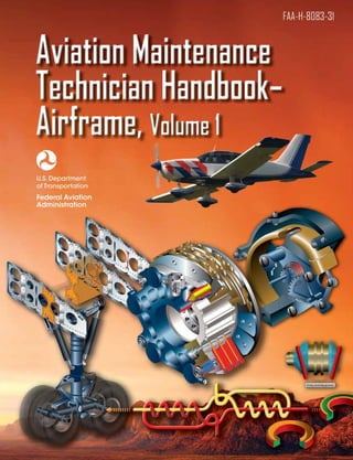


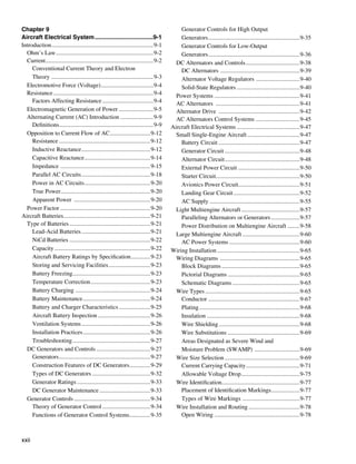

![Earlier, Cayley studied the center of gravity of flying
machines, as well as the effects of wing dihedral. Furthermore,
he pioneered directional control of aircraft by including the
earliest form of a rudder on his gliders. [Figure 1-1]
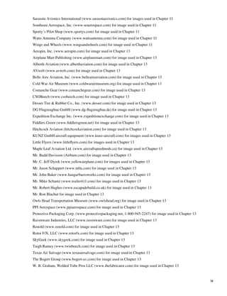
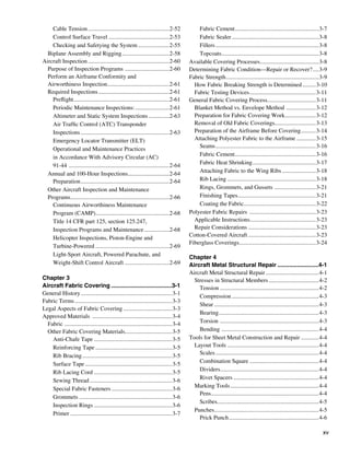
In the late 1800s, Otto Lilienthal built upon Cayley’s
discoveries. He manufactured and flew his own gliders
on over 2,000 flights. His willow and cloth aircraft had
wings designed from extensive study of the wings of birds.
Lilienthal also made standard use of vertical and horizontal
fins behind the wings and pilot station. Above all, Lilienthal
proved that man could fly. [Figure 1-2]
Octave Chanute, a retired railroad and bridge engineer,
was active in aviation during the 1890s. [Figure 1-3] His
interest was so great that, among other things, he published
a definitive work called “Progress in Flying Machines.” This
was the culmination of his effort to gather and study all the
Figure 1-2. Master of gliding and wing study, Otto Lilienthal (top)
and one of his more than 2,000 glider flights (bottom).
information available on aviation. With the assistance of
others, he built gliders similar to Lilienthal’s and then his
own. In addition to his publication, Chanute advanced aircraft
structure development by building a glider with stacked wings
incorporating the use of wires as wing supports.
The work of all of these men was known to the Wright
Brothers when they built their successful, powered airplane
in 1903. The first of its kind to carry a man aloft, the Wright
Flyer had thin, cloth-covered wings attached to what was
primarily truss structures made of wood. The wings contained
forward and rear spars and were supported with both struts
Figure 1-1. George Cayley, the father of aeronautics (top) and a and wires. Stacked wings (two sets) were also part of the
flying replica of his 1853 glider (bottom). Wright Flyer. [Figure 1-4]
1-2](https://image.slidesharecdn.com/faa-h-8083-31-amt-airframe-vol-1-130226145854-phpapp01/85/Faa-h-8083-31-amt-airframe-vol-1-28-320.jpg)
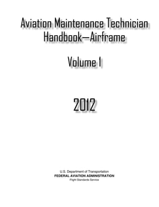
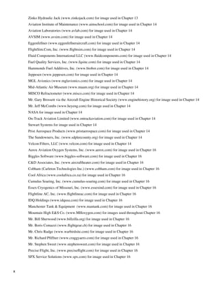
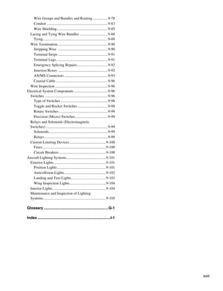
![still supported by wires, but a mast extending above the
fuselage enabled the wings to be supported from above, as
well as underneath. This made possible the extended wing
length needed to lift an aircraft with a single set of wings.
Bleriot used a Pratt truss-type fuselage frame. [Figure 1-5]
Figure 1-5. The world’s first mono-wing by Louis Bleriot.
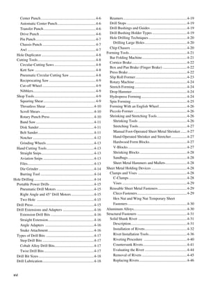
Figure 1-3. Octave Chanute gathered and published all of the More powerful engines were developed and airframe
aeronautical knowledge known to date in the late 1890s. Many structures changed to take advantage of the benefits. As
early aviators benefited from this knowledge. early as 1910, German Hugo Junkers was able to build an
aircraft with metal truss construction and metal skin due to
Powered heavier-than-air aviation grew from the Wright
the availability of stronger powerplants to thrust the plane
design. Inventors and fledgling aviators began building their
forward and into the sky. The use of metal instead of wood
own aircraft. Early on, many were similar to that constructed
for the primary structure eliminated the need for external
by the Wrights using wood and fabric with wires and struts
wing braces and wires. His J-1 also had a single set of wings
to support the wing structure. In 1909, Frenchman Louis
(a monoplane) instead of a stacked set. [Figure 1-6]
Bleriot produced an aircraft with notable design differences.
He built a successful mono-wing aircraft. The wings were
Figure 1-4. The Wright Flyer was the first successful powered aircraft. It was made primarily of wood and fabric.
1-3](https://image.slidesharecdn.com/faa-h-8083-31-amt-airframe-vol-1-130226145854-phpapp01/85/Faa-h-8083-31-amt-airframe-vol-1-29-320.jpg)
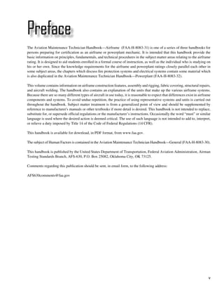
![Figure 1-6. The Junker J-1 all metal construction in 1910.
Leading up to World War I (WWI), stronger engines also
allowed designers to develop thicker wings with stronger
spars. Wire wing bracing was no longer needed. Flatter, lower
wing surfaces on high-camber wings created more lift. WWI
expanded the need for large quantities of reliable aircraft.
Used mostly for reconnaissance, stacked-wing tail draggers
with wood and metal truss frames with mostly fabric skin
dominated the wartime sky. [Figure 1-7] The Red Baron’s
Fokker DR-1 was typical.
Figure 1-7. World War I aircraft were typically stacked-wing fabric-
covered aircraft like this Breguet 14 (circa 1917).
Figure 1-8. The flying boat hull was an early semimonocoque design
In the 1920s, the use of metal in aircraft construction like this Curtiss HS-2L.
increased. Fuselages able to carry cargo and passengers
were developed. The early flying boats with their hull-type construction of the fuselage. [Figure 1-9] The fiberglass
construction from the shipbuilding industry provided the radome was also developed during this period.
blueprints for semimonocoque construction of fuselages.
[Figure 1-8] Truss-type designs faded. A tendency toward After WWII, the development of turbine engines led to
cleaner monowing designs prevailed. higher altitude flight. The need for pressurized aircraft
pervaded aviation. Semimonocoque construction needed
Into the 1930s, all-metal aircraft accompanied new lighter and to be made even stronger as a result. Refinements to the
more powerful engines. Larger semimonocoque fuselages all-metal semimonocoque fuselage structure were made to
were complimented with stress-skin wing designs. Fewer increase strength and combat metal fatigue caused by the
truss and fabric aircraft were built. World War II (WWII) pressurization-depressurization cycle. Rounded windows
brought about a myriad of aircraft designs using all metal and door openings were developed to avoid weak areas
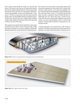
technology. Deep fuel-carrying wings were the norm, but the where cracks could form. Integrally machined copper
desire for higher flight speeds prompted the development of alloy aluminum skin resisted cracking and allowed thicker
thin-winged aircraft in which fuel was carried in the fuselage. skin and controlled tapering. Chemical milling of wing
The first composite structure aircraft, the De Havilland skin structures provided great strength and smooth high
Mosquito, used a balsa wood sandwich material in the performance surfaces. Variable contour wings became easier
1-4](https://image.slidesharecdn.com/faa-h-8083-31-amt-airframe-vol-1-130226145854-phpapp01/85/Faa-h-8083-31-amt-airframe-vol-1-30-320.jpg)
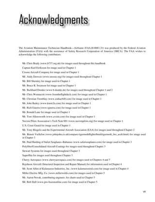
![Figure 1-9. The DeHavilland Mosquito, the first aircraft with foam
core honeycomb in the fuselage. Figure 1-10. The nearly all composite Cessna Citation Mustang
to construct. Increases in flight speed accompanying jet travel very light jet (VLJ).
brought about the need for thinner wings. Wing loading also
General
increased greatly. Multispar and box beam wing designs were
developed in response. An aircraft is a device that is used for, or is intended to be used
for, flight in the air. Major categories of aircraft are airplane,
In the 1960s, ever larger aircraft were developed to carry rotorcraft, glider, and lighter-than-air vehicles. [Figure 1-11]
passengers. As engine technology improved, the jumbo jet Each of these may be divided further by major distinguishing
was engineered and built. Still primarily aluminum with a features of the aircraft, such as airships and balloons. Both
semimonocoque fuselage, the sheer size of the airliners of are lighter-than-air aircraft but have differentiating features
the day initiated a search for lighter and stronger materials and are operated differently.
from which to build them. The use of honeycomb constructed
panels in Boeing’s airline series saved weight while not The concentration of this handbook is on the airframe of
compromising strength. Initially, aluminum core with aircraft; specifically, the fuselage, booms, nacelles, cowlings,
aluminum or fiberglass skin sandwich panels were used on fairings, airfoil surfaces, and landing gear. Also included are
wing panels, flight control surfaces, cabin floor boards, and the various accessories and controls that accompany these
other applications. structures. Note that the rotors of a helicopter are considered
part of the airframe since they are actually rotating wings.
A steady increase in the use of honeycomb and foam core By contrast, propellers and rotating airfoils of an engine on
sandwich components and a wide variety of composite an airplane are not considered part of the airframe.
materials characterizes the state of aviation structures from
the 1970s to the present. Advanced techniques and material The most common aircraft is the fixed-wing aircraft. As
combinations have resulted in a gradual shift from aluminum the name implies, the wings on this type of flying machine
to carbon fiber and other strong, lightweight materials. These are attached to the fuselage and are not intended to move
new materials are engineered to meet specific performance independently in a fashion that results in the creation of lift.
requirements for various components on the aircraft. Many One, two, or three sets of wings have all been successfully
airframe structures are made of more than 50 percent utilized. [Figure 1-12] Rotary-wing aircraft such as
advanced composites, with some airframes approaching helicopters are also widespread. This handbook discusses
100 percent. The term “very light jet” (VLJ) has come to features and maintenance aspects common to both fixed-
describe a new generation of jet aircraft made almost entirely wing and rotary-wing categories of aircraft. Also, in certain
of advanced composite materials. [Figure 1-10] It is possible cases, explanations focus on information specific to only
that noncomposite aluminum aircraft structures will become one or the other. Glider airframes are very similar to fixed-
obsolete as did the methods and materials of construction wing aircraft. Unless otherwise noted, maintenance practices
used by Cayley, Lilienthal, and the Wright Brothers. described for fixed-wing aircraft also apply to gliders. The
same is true for lighter-than-air aircraft, although thorough
1-5](https://image.slidesharecdn.com/faa-h-8083-31-amt-airframe-vol-1-130226145854-phpapp01/85/Faa-h-8083-31-amt-airframe-vol-1-31-320.jpg)
![Figure 1-11. Examples of different categories of aircraft, clockwise from top left: lighter-than-air, glider, rotorcraft, and airplane.
coverage of the unique airframe structures and maintenance
practices for lighter-than-air flying machines is not included
in this handbook.
The airframe of a fixed-wing aircraft consists of five principal
units: the fuselage, wings, stabilizers, flight control surfaces,
and landing gear. [Figure 1-13] Helicopter airframes consist
of the fuselage, main rotor and related gearbox, tail rotor (on
helicopters with a single main rotor), and the landing gear.
Airframe structural components are constructed from a wide
variety of materials. The earliest aircraft were constructed
primarily of wood. Steel tubing and the most common
material, aluminum, followed. Many newly certified aircraft
are built from molded composite materials, such as carbon
fiber. Structural members of an aircraft’s fuselage include
stringers, longerons, ribs, bulkheads, and more. The main
structural member in a wing is called the wing spar.
The skin of aircraft can also be made from a variety of
materials, ranging from impregnated fabric to plywood,
aluminum, or composites. Under the skin and attached to
the structural fuselage are the many components that support
airframe function. The entire airframe and its components are
joined by rivets, bolts, screws, and other fasteners. Welding,
adhesives, and special bonding techniques are also used.
Major Structural Stresses
Aircraft structural members are designed to carry a load or
to resist stress. In designing an aircraft, every square inch of
wing and fuselage, every rib, spar, and even each metal fitting
must be considered in relation to the physical characteristics
Figure 1-12. A monoplane (top), biplane (middle), and tri-wing
of the material of which it is made. Every part of the aircraft
aircraft (bottom). must be planned to carry the load to be imposed upon it.
1-6](https://image.slidesharecdn.com/faa-h-8083-31-amt-airframe-vol-1-130226145854-phpapp01/85/Faa-h-8083-31-amt-airframe-vol-1-32-320.jpg)
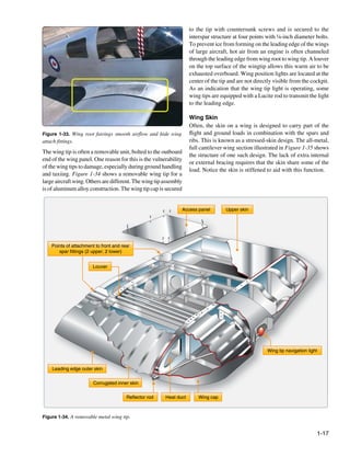
![Wings
Flight
controls
Powerplant
Stabilizers
Fuselage
Flight controls
Landing gear
Figure 1-13. Principal airframe units.
The determi ation of such loads is called stress analysis. Al
n tension, which stretches the aircraft. The tensile strength of
though planning the design is not the function of the aircraft a material is measured in pounds per square inch (psi) and is
technician, it is, nevertheless, important that the technician calculated by dividing the load (in pounds) re uired to pull the
q
understand and appreciate the stresses in olved in order to
v material apart by its cross-secional area (in square inches).
t
avoid changes in the original design through improper repairs.
Compression is the stress that res sts a crushing force.
i
The term “stress” is often used interchangeably with the [Figure 1-14B] The compressive strength of a material is
word “strain.” While related, they are not the same thing. also measured in psi. Compression is the stress that tends to
External loads or forces cause stress. Stress is a material’s shorten or squeeze aircraft parts.
internal resistance, or counterforce, that opposes deformation.
The degree of deformation of a material is strain. When Torsion is the stress that produces twisting. [Figure 1-14C]
a material is subjected to a load or force, that material is While moving the aircraft forward, the en ine also tends to
g
deformed, regardless of how strong the material is or how twist it to one side, but other aircraft components hold it on
light the load is. course. Thus, torsion is created. The torsion strength of a
material is its resistance to twisting or torque.
There are five major stresses [Figure 1-14] to which all
aircraft are subjected: Shear is the stress that resists the force tending to cause
• Tension one layer of a material to slide over an adjacent layer.
[Figure 1-14D] Two riveted plates in tension subject the
• Compression rivets to a shearing force. Usually, the shearing strength
• Torsion of a material is either equal to or less than its tensile or
compressive strength. Aircraft parts, especially screws, bolts,
• Shear
and rivets, are often subject to a shearing force.
• Bending
Bending stress is a combination of compression and tension.
Tension is the stress that resists a force that tends to pull The rod in Figure 1-14E has been short ned (compressed) on
e
something apart. [Figure 1-14A] The engine pulls the aircraft the inside of the bend and stretched on the outside of the bend.
forward, but air resistance tries to hold it back. The result is
1-7](https://image.slidesharecdn.com/faa-h-8083-31-amt-airframe-vol-1-130226145854-phpapp01/85/Faa-h-8083-31-amt-airframe-vol-1-33-320.jpg)
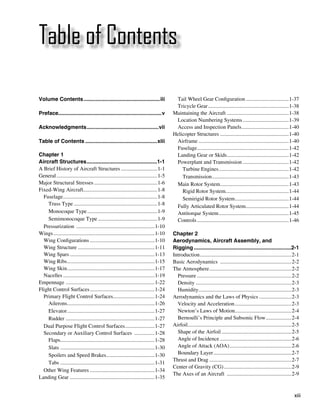
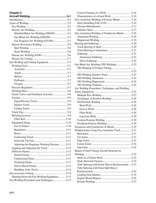
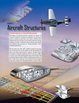
![The truss-type fuselage frame is usually constructed of steel
tubing welded together in such a manner that all members Skin Former
of the truss can carry both tension and compression loads.
[Figure 1-15] In some aircraft, principally the light, single-
engine models, truss fuselage frames may be constructed of
aluminum alloy and may be riveted or bolted into one piece,
with cross-bracing achieved by using solid rods or tubes.
Longeron
Diagonal web members
Bulkhead
Figure 1-16. An airframe using monocoque construction.
design but, additionally, the skin is reinforced by longitudinal
Vertical web members members called longerons. Longerons usually extend across
several frame members and help the skin support primary
bending loads. They are typically made of aluminum alloy
Figure 1-15. A truss-type fuselage. A Warren truss uses mostly
Figure 1-2. The Warren truss. either of a single piece or a built-up construction.
diagonal bracing.
Monocoque Type Stringers are also used in the semimonocoque fuselage. These
longitudinal members are typically more numerous and lighter
The monocoque (single shell) fuselage relies largely on the
in weight than the longerons. They come in a variety of shapes
strength of the skin or covering to carry the primary loads.
and are usually made from single piece aluminum alloy
The design may be di ided into two classes:
v
extrusions or formed aluminum. Stringers have some rigidity
1. Monocoque but are chiefly used for giving shape and for attachment of
2. Semi onocoque
m the skin. Stringers and longerons together prevent tension
and compression from bending the fuselage. [Figure 1-17]
Different porions of the same fuselage may belong to either
t
of the two classes, but most modern aircraft are considered
to be of semimonocoque type construction. Longeron Skin
The true monocoque construction uses formers, frame
assemblies, and bulkheads to give shape to the fuselage.
[Figure 1-16] The heaviest of these structural members are
located at intervals to carry concentrated loads and at points
where fittings are used to attach other units such as wings,
powerplants, and stabilizers. Since no other bracing members
are present, the skin must carry the primary stresses and
keep the fuselage rigid. Thus, the biggest problem involved
in mono oque construction is maintaining enough strength
c
while keeping the weight within allowable limits.
Stringer
Semimonocoque Type
To overcome the strength/weight problem of monocoque Bulkhead
construction, a modification called semi onocoque
m
construction was devel ped. It also consists of frame
o Figure 1-17. The most common airframe construction is
assemblies, bulkheads, and formers as used in the monocoque semimonocoque.
1-9](https://image.slidesharecdn.com/faa-h-8083-31-amt-airframe-vol-1-130226145854-phpapp01/85/Faa-h-8083-31-amt-airframe-vol-1-35-320.jpg)
![Other bracing between the longerons and stringers can also construction, may with tand considerable damage and still
s
be used. Often referred to as web members, these additional be strong enough to hold together.
support pieces may be installed vertically or diagonally. It
must be noted that manufacturers use different nomenclature Fuselages are generally constructed in two or more sections.
to describe structural members. For example, there is often On small aircraft, they are generally made in two or three
little difference between some rings, frames, and formers. sections, while larger aircraft may be made up of as many as
One manufacturer may call the same type of brace a ring or six sections or more before being assembled.
a frame. Manufacturer instructions and specifications for a
specific aircraft are the best guides. Pressurization
Many aircraft are pressurized. This means that air is pumped
The semimonocoque fuselage is constructed primarily of into the cabin after takeoff and a difference in pressure
alloys of aluminum and magnesium, although steel and between the air inside the cabin and the air outside the cabin is
titanium are sometimes found in areas of high temperatures. established. This differential is regulated and maintained. In
Individually, no one of the aforementioned components is this manner, enough oxygen is made available for passengers
strong enough to carry the loads imposed during flight and to breathe normally and move around the cabin without
landing. But, when combined, those components form a special equipment at high altitudes.
strong, rigid framework. This is accomplished with gussets,
rivets, nuts and bolts, screws, and even friction stir welding. Pressurization causes significant stress on the fuselage
A gusset is a type of connection bracket that adds strength. structure and adds to the complexity of design. In addition
[Figure 1-18] to withstanding the difference in pressure between the air
inside and outside the cabin, cycling from unpressurized to
pressurized and back again each flight causes metal fatigue.
To deal with these impacts and the other stresses of flight,
nearly all pressurized aircraft are semimonocoque in design.
Pressurized fuselage structures undergo extensive periodic
inspections to ensure that any damage is discovered and
repaired. Repeated weakness or failure in an area of structure
may require that section of the fuselage be modified or
redesigned.
Wings
Wing Configurations
Wings are airfoils that, when moved rapidly through the
air, create lift. They are built in many shapes and sizes.
Wing design can vary to provide certain desirable flight
Figure 1-18. Gussets are used to increase strength. characteristics. Control at various operating speeds, the
amount of lift generated, balance, and stability all change as
the shape of the wing is altered. Both the leading edge and
To summarize, in semimonocoque fuselages, the strong, the trailing edge of the wing may be straight or curved, or
heavy longerons hold the bulkheads and formers, and these, one edge may be straight and the other curved. One or both
in turn, hold the stringers, braces, web members, etc. All are edges may be tapered so that the wing is narrower at the tip
designed to be attached together and to the skin to achieve than at the root where it joins the fuselage. The wing tip may
the full strength benefits of semimonocoque design. It is be square, rounded, or even pointed. Figure 1-19 shows a
important to recognize that the metal skin or covering carries number of typical wing leading and trailing edge shapes.
part of the load. The fuselage skin thickness can vary with the
load carried and the stresses sustained at a particular location. The wings of an aircraft can be attached to the fuselage at
the top, mid-fuselage, or at the bottom. They may extend
The advantages of the semimonocoque fuselage are many. perpendicular to the horizontal plain of the fuselage or can
The bulkheads, frames, stringers, and longerons facilitate the angle up or down slightly. This angle is known as the wing
de ign and construction of a streamlined fuselage that is both
s dihedral. The dihedral angle affects the lateral stability of
rigid and strong. Spreading loads among these structures and the aircraft. Figure 1-20 shows some common wing attach
the skin means no single piece is failure critical. This means points and dihedral angle.
that a semimonocoque fuselage, because of its stressed-skin
1-10](https://image.slidesharecdn.com/faa-h-8083-31-amt-airframe-vol-1-130226145854-phpapp01/85/Faa-h-8083-31-amt-airframe-vol-1-36-320.jpg)
![Tapered leading edge, Tapered leading and
Delta wing
straight trailing edge trailing edges
Straight leading and Straight leading edge,
Sweptback wings
trailing edges tapered trailing edge
Figure 1-19. Various wing design shapes yield different performance.
Wing Structure
The wings of an aircraft are designed to lift it into the air.
Their particular design for any given aircraft depends on a
number of factors, such as size, weight, use of the aircraft,
Low wing Dihedral desired speed in flight and at landing, and desired rate of
climb. The wings of aircraft are designated left and right,
corresponding to the left and right sides of the operator when
seated in the cockpit. [Figure 1-21]
High wing Mid wing
Often wings are of full cantilever design. This means they
are built so that no external bracing is needed. They are
supported internally by structural members assisted by the
skin of the aircraft. Other aircraft wings use external struts
Gull wing Inverted gull or wires to assist in supporting the wing and carrying the
aerodynamic and landing loads. Wing support cables and
Figure 1-20. Wing attach points and wing dihedrals. struts are generally made from steel. Many struts and their
1-11](https://image.slidesharecdn.com/faa-h-8083-31-amt-airframe-vol-1-130226145854-phpapp01/85/Faa-h-8083-31-amt-airframe-vol-1-37-320.jpg)
![Left wing
Right wing
Figure 1-21. “Left” and “right” on an aircraft are oriented to the perspective of a pilot sitting in the cockpit.
attach fittings have fairings to reduce drag. Short, nearly bulkheads running chordwise (leading edge to trailing edge).
vertical supports called jury struts are found on struts that The spars are the principle structural members of a wing.
attach to the wings a great distance from the fuselage. This They support all distributed loads, as well as concentrated
serves to subdue strut movement and oscillation caused by weights such as the fuselage, landing gear, and engines. The
the air flowing around the strut in flight. Figure 1-22 shows skin, which is attached to the wing structure, carries part of
samples of wings using external bracing, also known as the loads imposed during flight. It also transfers the stresses
semicantilever wings. Cantilever wings built with no external to the wing ribs. The ribs, in turn, transfer the loads to the
bracing are also shown. wing spars. [Figure 1-23]
Aluminum is the most common material from which In general, wing construction is based on one of three
to construct wings, but they can be wood covered with fundamental designs:
fabric, and occasionally a magnesium alloy has been used. 1. Monospar
Moreover, modern aircraft are tending toward lighter and
stronger materials throughout the airframe and in wing 2. Multispar
construction. Wings made entirely of carbon fiber or other 3. Box beam
composite materials exist, as well as wings made of a
combination of materials for maximum strength to weight Modification of these basic designs may be adopted by
performance. various manufacturers.
The internal structures of most wings are made up of spars The monospar wing incorporates only one main spanwise or
and stringers running spanwise and ribs and formers or longitudinal member in its construction. Ribs or bulkheads
Wire braced biplane
Full cantilever Semicantilever
Long struts braced with jury struts
Figure 1-22. Externally braced wings, also called semicantilever wings, have wires or struts to support the wing. Full cantilever wings
have no external bracing and are supported internally.
1-12](https://image.slidesharecdn.com/faa-h-8083-31-amt-airframe-vol-1-130226145854-phpapp01/85/Faa-h-8083-31-amt-airframe-vol-1-38-320.jpg)
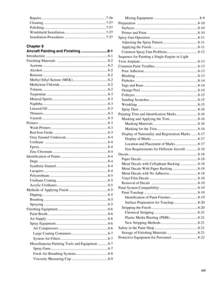
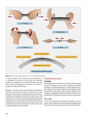
![Ribs Rear spar
Stringer
Nose rib
Ribs
Front spar
Skin
Figure 1-23. Wing structure nomenclature.
supply the necessary contour or shape to the airfoil. Although the upper surface of the wing and stiffeners on the lower
the strict monospar wing is not common, this type of design surface is sometimes used. Air transport category aircraft
modified by the addition of false spars or light shear webs often utilize box beam wing construction.
along the trailing edge for support of control surfaces is
sometimes used. Wing Spars
Spars are the principal structural members of the wing. They
The multispar wing incorporates more than one main correspond to the longerons of the fuseage. They run parallel
l
longitudinal member in its construction. To give the wing to the lateral axis of the aircraft, from the fuselage toward
contour, ribs or bulkheads are often included. the tip of the wing, and are usually attached to the fuselage
by wing fittings, plain beams, or a truss.
The box beam type of wing construction uses two main
longitudinal members with connecting bulkheads to Spars may be made of metal, wood, or composite materials
furnish additional strength and to give contour to the wing. depending on the design criteria of a specific aircraft.
[Figure 1-24] A corrugated sheet may be placed between Wooden spars are usually made from spruce. They can be
the bulkheads and the smooth outer skin so that the wing generally classified into four different types by their cross-
can better carry tension and compression loads. In some sectional configu ation. As shown in Figure 1-25, they may
r
cases, heavy longitudinal stiffeners are substituted for the be (A) solid, (B) box shaped, (C) partly hollow, or (D) in
corrugated sheets. A combination of corrugated sheets on the form of an I-beam. Lamination of solid wood spars is
Figure 1-24. Box beam construction.
1-13](https://image.slidesharecdn.com/faa-h-8083-31-amt-airframe-vol-1-130226145854-phpapp01/85/Faa-h-8083-31-amt-airframe-vol-1-39-320.jpg)
![A B C D E
Figure 1-25. Typical wooden wing spar cross-sections.
often used to increase strength. Laminated wood can also be foundation for attaching the skin. Although the spar shapes
found in box shaped spars. The spar in Figure 1-25E has had in Figure 1-26 are typi al, actual wing spar configuraions
c t
material removed to reduce weight but retains the strength assume many forms. For example, the web of a spar may be
of a rectangular spar. As can be seen, most wing spars are a plate or a truss as shown in Figure 1-27. It could be built up
basically rectangular in shape with the long dimension of the from light weight materials with vertical stiffeners employed
cross-section oriented up and down in the wing. for strength. [Figure 1-28]
Currently, most manufactured aircraft have wing spars
made of solid extruded aluminum or aluminum extrusions Upper cap member
riveted together to form the spar. The increased use of Diagonal tube
composites and the combining of materials should make
airmen vigilant for wings spars made from a variety of Vertical tube
materials. Figure 1-26 shows examples of metal wing spar
cross-sections.
In an I–beam spar, the top and bottom of the I–beam are
called the caps and the vertical section is called the web.
The entire spar can be extruded from one piece of metal
but often it is built up from multiple extrusions or formed Lower cap member
angles. The web forms the principal depth portion of the
spar and the cap strips (extrusions, formed angles, or milled
sections) are attached to it. Together, these members carry Figure 1-27. A truss wing spar.
the loads caused by wing bending, with the caps providing a
Figure 1-26. Examples of metal wing spar shapes.
1-14](https://image.slidesharecdn.com/faa-h-8083-31-amt-airframe-vol-1-130226145854-phpapp01/85/Faa-h-8083-31-amt-airframe-vol-1-40-320.jpg)
![Upper spar cap Upper spar cap
Stiffener
Rivets
Splice
Up
pe
rs
pa
rw
Lo eb
we
rs
Rib attach angle pa
rw
eb
Lower spar cap
Lower spar cap
Figure 1-28. A plate web wing spar with vertical stiffeners. Figure 1-30. A fail-safe spar with a riveted spar web.
It could also have no stiffeners but might contain flanged False spars are commonly used in wing design. They are
holes for reducing weight but maintaining strength. Some longitudinal members like spars but do not extend the entire
metal and composite wing spars retain the I-beam concept spanwise length of the wing. Often, they are used as hinge
but use a sine wave web. [Figure 1-29] attach points for control surfaces, such as an aileron spar.
Wing Ribs
Sine wave web
Ribs are the structural crosspieces that combine with spars
and stringers to make up the framework of the wing. They
Caps usually extend from the wing leading edge to the rear spar
or to the trailing edge of the wing. The ribs give the wing
its cambered shape and transmit the load from the skin and
stringers to the spars. Similar ribs are also used in ailerons,
elevators, rudders, and stabilizers.
Wing ribs are usually manufactured from either wood or
metal. Aircraft with wood wing spars may have wood or
Figure 1-29. A sine wave wing spar can be made from aluminum metal ribs while most aircraft with metal spars have metal
or composite materials. ribs. Wood ribs are usually manufactured from spruce. The
three most common types of wooden ribs are the plywood
Additionally, fail-safe spar web design exists. Fail-safe web, the lightened plywood web, and the truss types. Of these
means that should one member of a complex structure fail, three, the truss type is the most efficient because it is strong
some other part of the structure assumes the load of the failed and lightweight, but it is also the most complex to construct.
member and permits continued operation. A spar with fail-
safe construction is shown in Figure 1-30. This spar is made Figure 1-31 shows wood truss web ribs and a lightened
in two sections. The top section consists of a cap riveted to plywood web rib. Wood ribs have a rib cap or cap strip
the upper web plate. The lower section is a single extrusion fastened around the entire perimeter of the rib. It is usually
consisting of the lower cap and web plate. These two sections made of the same material as the rib itself. The rib cap stiffens
are spliced together to form the spar. If either section of this and strengthens the rib and provides an attaching surface
type of spar breaks, the other section can still carry the load. for the wing covering. In Figure 1-31A, the cross-section
This is the fail-safe feature. of a wing rib with a truss-type web is illustrated. The dark
rectangular sections are the front and rear wing spars. Note that
As a rule, a wing has two spars. One spar is usually located to reinforce the truss, gussets are used. In Figure 1-31B, a truss
near the front of the wing, and the other about two-thirds of web rib is shown with a continuous gusset. It provides greater
the distance toward the wing’s trailing edge. Regardless of support throughout the entire rib with very little additional
type, the spar is the most important part of the wing. When weight. A continuous gusset stiffens the cap strip in the plane
other structural members of the wing are placed under load, of the rib. This aids in preventing buckling and helps to obtain
most of the resulting stress is passed on to the wing spar. better rib/skin joints where nail-gluing is used. Such a rib can
resist the driving force of nails better than the other types.
1-15](https://image.slidesharecdn.com/faa-h-8083-31-amt-airframe-vol-1-130226145854-phpapp01/85/Faa-h-8083-31-amt-airframe-vol-1-41-320.jpg)
![the trailing edge of the wing. Wing butt ribs may be found
at the inboard edge of the wing where the wing attaches
A
to the fuselage. Depending on its location and method of
attachment, a butt rib may also be called a bulkhead rib or
a compression rib if it is designed to receive compression
loads that tend to force the wing spars together.
B
Since the ribs are laterally weak, they are strengthened in some
wings by tapes that are woven above and below rib sections
to prevent sidewise bending of the ribs. Drag and anti-drag
C
wires may also be found in a wing. In Figure 1-32, they are
shown criss rossed between the spars to form a truss to resist
c
forces acting on the wing in the direction of the wing chord.
These tension wires are also referred to as tie rods. The wire
Figure 1-31. Examples of wing ribs constructed of wood.
designed to resist the back ard forces is called a drag wire;
w
Continuous gussets are also more easily handled than the many the anti-drag wire resists the forward forces in the chord
small separate gussets otherwise required. Figure 1-31C shows direction. Figure 1-32 illustrates the structural components
a rib with a lighten plywood web. It also contains gussets to of a basic wood wing.
support the web/cap strip interface. The cap strip is usually
laminated to the web, especially at the leading edge. At the inboard end of the wing spars is some form of wing
attach fitting as illustrated in Figure 1-32. These provide
A wing rib may also be referred to as a plain rib or a main rib. a strong and secure method for attaching the wing to the
Wing ribs with specialized locations or functions are given fuselage. The interface between the wing and fuselage is
names that reflect their uniqueness. For example, ribs that often covered with a fairing to achieve smooth airflow in this
are located entirely forward of the front spar that are used to area. The fairing(s) can be removed for access to the wing
shape and strengthen the wing leading edge are called nose attach fittings. [Figure 1-33]
ribs or false ribs. False ribs are ribs that do not span the entire
wing chord, which is the distance from the leading edge to
Leading edge strip Nose rib or false rib
Wing tip Front spar Anti-drag wire or tire rod Drag wire or tire rod Wing attach fittings
False spar or aileron spar Rear spar Wing rib or plain rib
Aileron Aileron hinge Wing butt rib (or compression rib or bulkhead rib)
Figure 1-32. Basic wood wing structure and components.
1-16](https://image.slidesharecdn.com/faa-h-8083-31-amt-airframe-vol-1-130226145854-phpapp01/85/Faa-h-8083-31-amt-airframe-vol-1-42-320.jpg)
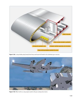
![Trailing edge sandwich panels
constant-thickness core
Wing leading edge
Spoiler sandwich panel
tapered core, solid wedge
Trailing edge sandwich panels
constant-thickness core
Inboard flap
Spoiler sandwich panel
Outboard flap tapered core, solid wedge
Aileron tab sandwich panel Aileron tab sandwich panel
tapered core, Phenolic wedge constant-thickness core
Trailing edge wedge sandwich panel
tapered core, cord wedge
Figure 1-38. Honeycomb wing construction on a large jet transport aircraft.
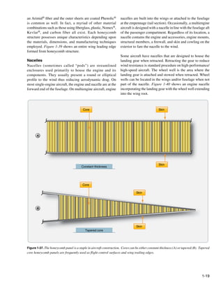
The framework of a nacelle usually consists of structural components inside. Both are usually made of sheet aluminum
members similar to those of the fuselage. Lengthwise or magnesium alloy with stainless steel or titanium alloys
members, such as longerons and stringers, combine with being used in high-temperature areas, such as around the
horizontal/vertical members, such as rings, formers, and exhaust exit. Regardless of the material used, the skin is
bulkheads, to give the nacelle its shape and structural typically attached to the framework with rivets.
integrity. A firewall is incorporated to isolate the engine
compartment from the rest of the aircraft. This is basically a Cowling refers to the detachable panels covering those areas
stainless steel or titanium bulkhead that contains a fire in the into which access must be gained regularly, such as the engine
confines of the nacelle rather than letting it spread throughout and its accessories. It is designed to provide a smooth airflow
the airframe. [Figure 1-41] over the nacelle and to protect the engine from damage. Cowl
panels are generally made of aluminum alloy construction.
Engine mounts are also found in the nacelle. These are However, stainless steel is often used as the inner skin aft
the structural assemblies to which the engine is fastened. of the power section and for cowl flaps and near cowl flap
They are usually constructed from chrome/molybdenum openings. It is also used for oil cooler ducts. Cowl flaps are
steel tubing in light aircraft and forged chrome/nickel/ moveable parts of the nacelle cowling that open and close
molybdenum assemblies in larger aircraft. [Figure 1-42] to regulate engine temperature.
The exterior of a nacelle is covered with a skin or fitted with There are many engine cowl designs. Figure 1-43 shows an
a cowling which can be opened to access the engine and exploded view of the pieces of cowling for a horizontally
1-20](https://image.slidesharecdn.com/faa-h-8083-31-amt-airframe-vol-1-130226145854-phpapp01/85/Faa-h-8083-31-amt-airframe-vol-1-46-320.jpg)
![Figure 1-41. An engine nacelle firewall.
opposed engine on a light aircraft. It is attached to the nacelle Figure 1-42. Various aircraft engine mounts.
by means of screws and/or quick release fasteners. Some
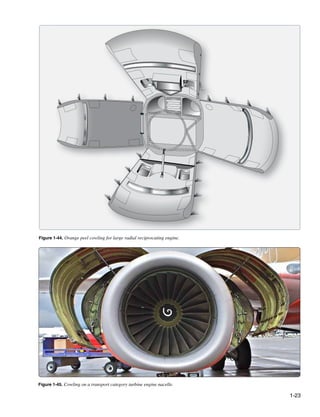
large reciprocating engines are enclosed by “orange peel”
cowlings which provide excellent access to components
inside the nacelle. [Figure 1-44] These cowl panels are
attached to the forward firewall by mounts which also serve
as hinges for opening the cowl. The lower cowl mounts are
secured to the hinge brackets by quick release pins. The side
and top panels are held open by rods and the lower panel is
retained in the open position by a spring and a cable. All of
the cowling panels are locked in the closed position by over-
center steel latches which are secured in the closed position
by spring-loaded safety catches.
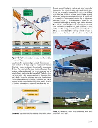
An example of a turbojet engine nacelle can be seen in
Figure 1-45. The cowl panels are a combination of fixed and
easily removable panels which can be opened and closed
during maintenance. A nose cowl is also a feature on a jet Figure 1-43. Typical cowling for a horizontally opposed
engine nacelle. It guides air into the engine. reciprocating engine.
The tail cone serves to close and streamline the aft end of
Empennage most fuselages. The cone is made up of structural members
The empennage of an aircraft is also known as the tail like those of the fuselage; however, cones are usually of
section. Most empennage designs consist of a tail cone, lighter con truction since they receive less stress than the
s
fixed aerodynamic surfaces or stabilizers, and movable fuselage. [Figure 1-46]
aerodynamic surfaces.
1-22](https://image.slidesharecdn.com/faa-h-8083-31-amt-airframe-vol-1-130226145854-phpapp01/85/Faa-h-8083-31-amt-airframe-vol-1-48-320.jpg)
![Frame Longeron
Skin
Stringer
Rib
Stringer Bulkhead
Spars Skin
Figure 1-46. The fuselage terminates at the tail cone with similar
but more lightweight construction. Figure 1-48. Vertical stabilizer.
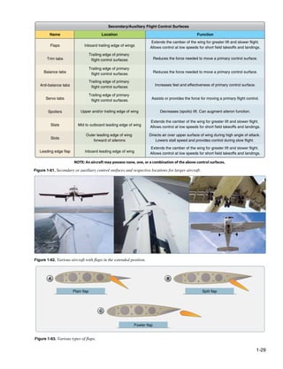
The other components of the typical empennage are of any overloads to the fuselage. A horizontal stabilizer is built
heavier construction than the tail cone. These members the same way.
include fixed surfaces that help stabilize the aircraft and
movable surfaces that help to direct an aircraft during flight. The rudder and elevator are flight control surfaces that are
The fixed surfaces are the horizonal stabilizer and vertical
t also part of the empennage discussed in the next section of
stabilizer. The movable surfaces are usually a rudder located this chapter.
at the aft edge of the vertical stabilizer and an elevator located
at the aft edge the horizontal stabilizer. [Figure 1-47] Flight Control Surfaces
The directional control of a fixed-wing aircraft takes place
Vertical stabilizer around the lateral, longitudinal, and vertical axes by means
of flight control surfaces designed to create movement about
these axes. These control devices are hinged or movable
Horizontal stabilizer Rudder surfaces through which the attitude of an aircraft is controlled
during takeoff, flight, and landing. They are usually divided
into two major groups: 1) pri ary or main flight control
m
Trim tabs surfaces and 2) secondary or auxiliary control surfaces.
Primary Flight Control Surfaces
The primary flight control surfaces on a fixed-wing aircraft
include: ailerons, elevators, and the rudder. The ailerons are
attached to the trailing edge of both wings and when moved,
Elevator
rotate the aircraft around the longitudinal axis. The elevator
is attached to the trailing edge of the horizontal stabilizer.
Figure 1-47. Components of a typical empennage. When it is moved, it alters aircraft pitch, which is the attitude
about the horizontal or lateral axis. The rudder is hinged to
The structure of the stabilizers is very similar to that which the trailing edge of the vertical stabilizer. When the rudder
is used in wing construction. Figure 1-48 shows a typical changes position, the aircraft rotates about the vertical axis
vertical stabilizer. Notice the use of spars, ribs, stringers, (yaw). Figure 1-49 shows the primary flight controls of a
and skin like those found in a wing. They perform the light aircraft and the movement they create relative to the
same functions shaping and supporting the stabilizer and three axes of flight.
transferring stresses. Bending, torsion, and shear created
by air loads in flight pass from one structural member to Primary control surfaces are usually similar in construcion
t
another. Each member absorbs some of the stress and passes to one another and vary only in size, shape, and methods of
the remainder on to the others. Ultimately, the spar transmits
1-24](https://image.slidesharecdn.com/faa-h-8083-31-amt-airframe-vol-1-130226145854-phpapp01/85/Faa-h-8083-31-amt-airframe-vol-1-50-320.jpg)
![Performed to manufacturer’s instructions, balancing usually
consists of assuring that the center of gravity of a particular
Up aileron
device is at or forward of the hinge point. Failure to properly
balance a control surface could lead to catastrophic failure.
Figure 1-52 illustrates several aileron configurations with Down aileron
their hinge points well aft of the leading edge. This is a
common design feature used to prevent flutter.
Figure 1-54. Differential aileron control movement. When one
aileron is moved down, the aileron on the opposite wing is deflected
upward.
Figure 1-52. Aileron hinge locations are very close to but aft of the The pilot’s request for aileron movement and roll are
center of gravity to prevent flutter. transmitted from the cockpit to the actual control surface in a
variety of ways depending on the aircraft. A system of control
Ailerons cables and pulleys, push-pull tubes, hydraulics, electric, or a
Ailerons are the primary flight control surfaces that move the combination of these can be employed. [Figure 1-55]
aircraft about the longitudinal axis. In other words, movement
of the ailerons in flight causes the aircraft to roll. Ailerons Stop
are usually located on the outboard trailing edge of each of
the wings. They are built into the wing and are calculated as
Elevator cables
part of the wing’s surface area. Figure 1-53 shows aileron
locations on various wing tip designs.
Tether stop
Stop
To ailerons
Note pivots not on center of shaft
Figure 1-55. Transferring control surface inputs from the cockpit.
Figure 1-53. Aileron location on various wings.
Simple, light aircraft usually do not have hydraulic or electric
fly-by-wire aileron control. These are found on heavy and
Ailerons are controlled by a side-to-side motion of the control high-performance aircraft. Large aircraft and some high-
stick in the cockpit or a rotation of the control yoke. When performance aircraft may also have a second set of ailerons
the aileron on one wing deflects down, the aileron on the located inboard on the trailing edge of the wings. These are
opposite wing deflects upward. This amplifies the movement part of a complex system of primary and secondary control
of the aircraft around the longitudinal axis. On the wing on surfaces used to provide lateral control and stability in flight.
which the aileron trailing edge moves downward, camber is At low speeds, the ailerons may be augmented by the use
increased and lift is increased. Conversely, on the other wing, of flaps and spoilers. At high speeds, only inboard aileron
the raised aileron decreases lift. [Figure 1-54] The result is deflection is required to roll the aircraft while the other control
a sensitive response to the control input to roll the aircraft. surfaces are locked out or remain stationary. Figure 1-56
1-26](https://image.slidesharecdn.com/faa-h-8083-31-amt-airframe-vol-1-130226145854-phpapp01/85/Faa-h-8083-31-amt-airframe-vol-1-52-320.jpg)
![illustrates the location of the typical flight control surfaces to the right. The left pedal is rigged to simultaneously move
found on a transport category aircraft. aft. When the left pedal is pushed forward, the nose of the
aircraft moves to the left.
Elevator
The elevator is the primary flight control surface that moves As with the other primary flight controls, the transfer of the
the aircraft around the horizontal or lateral axis. This causes movement of the cockpit controls to the rudder varies with
the nose of the aircraft to pitch up or down. The elevator is the complexity of the aircraft. Many aircraft incorporate the
hinged to the trailing edge of the horizontal stabilizer and directional movement of the nose or tail wheel into the rudder
typically spans most or all of its width. It is controlled in the control system for ground operation. This allows the operator
cockpit by pushing or pulling the control yoke forward or aft. to steer the aircraft with the rudder pedals during taxi when
the airspeed is not high enough for the control surfaces to be
Light aircraft use a system of control cables and pulleys or effective. Some large aircraft have a split rudder arrangement.
push pull tubes to transfer cockpit inputs to the movement This is actually two rudders, one above the other. At low
of the elevator. High performance and large aircraft speeds, both rudders deflect in the same direction when the
typically employ more complex systems. Hydraulic power pedals are pushed. At higher speeds, one of the rudders
is commonly used to move the elevator on these aircraft. On becomes inoperative as the deflection of a single rudder is
aircraft equipped with fly-by-wire controls, a combination aerodynamically sufficient to maneuver the aircraft.
of electrical and hydraulic power is used.
Dual Purpose Flight Control Surfaces
Rudder The ailerons, elevators, and rudder are considered
The rudder is the primary control surface that causes an conventional primary control surfaces. However, some
aircraft to yaw or move about the vertical axis. This provides aircraft are designed with a control surface that may serve a
directional control and thus points the nose of the aircraft dual purpose. For example, elevons perform the combined
in the direction desired. Most aircraft have a single rudder functions of the ailerons and the elevator. [Figure 1-57]
hinged to the trailing edge of the vertical stabilizer. It is
controlled by a pair of foot-operated rudder pedals in the A movable horizontal tail section, called a stabilator, is a
cockpit. When the right pedal is pushed forward, it deflects control surface that combines the action of both the horizontal
the rudder to the right which moves the nose of the aircraft stabilizer and the elevator. [Figure 1-58] Basically, a
Flight spoilers
Outboard aileron
Inboard aileron
Figure 1-56. Typical flight control surfaces on a transport category aircraft.
1-27](https://image.slidesharecdn.com/faa-h-8083-31-amt-airframe-vol-1-130226145854-phpapp01/85/Faa-h-8083-31-amt-airframe-vol-1-53-320.jpg)
![edge. Movement of the ruddervators can alter the movement
Elevons
of the aircraft around the horizontal and/or vertical axis.
Additionally, some aircraft are equipped with flaperons.
[Figure 1-60] Flaperons are ailerons which can also act as
flaps. Flaps are secondary control surfaces on most wings,
discussed in the next section of this chapter.
Flaperons
Figure 1-57. Elevons.
Figure 1-60. Flaperons.
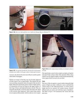
Secondary or Auxiliary Control Surfaces
There are several secondary or auxiliary flight control
surfaces. Their names, locations, and functions of those for
most large aircraft are listed in Figure 1-61.
Flaps
Figure 1-58. A stabilizer and index marks on a transport category
aircraft. Flaps are found on most aircraft. They are usually inboard on
the wings’ trailing edges adjacent to the fuselage. Leading
stabilator is a horizontal stabilizer that can also be rotated edge flaps are also common. They extend forward and down
about the horizontal axis to affect the pitch of the aircraft. from the inboard wing leading edge. The flaps are lowered
A ruddervator combines the action of the rudder and elevator. to increase the camber of the wings and provide greater lift
[Figure 1-59] This is possible on aircraft with V–tail and control at slow speeds. They enable landing at slower
empennages where the traditional horizontal and vertical speeds and shorten the amount of runway required for takeoff
stabilizers do not exist. Instead, two stabilizers angle upward and landing. The amount that the flaps extend and the angle
and outward from the aft fuselage in a “V” configuration. they form with the wing can be selected from the cockpit.
Each contains a movable ruddervator built into the trailing Typically, flaps can extend up to 45–50°. Figure 1-62 shows
various aircraft with flaps in the extended position.
Flaps are usually constructed of materials and with techniques
used on the other airfoils and control surfaces of a particular
aircraft. Aluminum skin and structure flaps are the norm on
Ruddervator light aircraft. Heavy and high-performance aircraft flaps
may also be aluminum, but the use of composite structures
is also common.
There are various kinds of flaps. Plain flaps form the trailing
edge of the wing when the flap is in the retracted position.
[Figure 1-63A] The airflow over the wing continues over the
upper and lower surfaces of the flap, making the trailing edge
of the flap essentially the trailing edge of the wing. The plain
Figure 1-59. Ruddervator.
1-28](https://image.slidesharecdn.com/faa-h-8083-31-amt-airframe-vol-1-130226145854-phpapp01/85/Faa-h-8083-31-amt-airframe-vol-1-54-320.jpg)
![flap is hinged so that the trailing edge can be lowered. This
increases wing camber and provides greater lift.
A split flap is normally housed under the trailing edge of the Hinge point
wing. [Figure 1-63B] It is usually just a braced flat metal
plate hinged at several places along its leading edge. The Actuator
upper surface of the wing extends to the trailing edge of the
flap. When deployed, the split flap trailing edge lowers away
from the trailing edge of the wing. Airflow over the top of the
wing remains the same. Airflow under the wing now follows
the camber created by the lowered split flap, increasing lift.
Flap extended
Fowler flaps not only lower the trailing edge of the wing when Flap retracted
deployed but also slide aft, effectively increasing the area of the
wing. [Figure 1-63C] This creates more lift via the increased Retractable nose
surface area, as well as the wing camber. When stowed, the
fowler flap typically retracts up under the wing trailing edge Figure 1-65. Leading edge flaps.
similar to a split flap. The sliding motion of a fowler flap can
be accomplished with a worm drive and flap tracks. The differing designs of leading edge flaps essentially
provide the same effect. Activation of the trailing edge
An enhanced version of the fowler flap is a set of flaps flaps automatically deploys the leading edge flaps, which
that actually contains more than one aerodynamic surface. are driven out of the leading edge and downward, extending
Figure 1-64 shows a triple-slotted flap. In this configuration, the camber of the wing. Figure 1-66 shows a Krueger flap,
the flap consists of a fore flap, a mid flap, and an aft flap. recognizable by its flat mid-section.
When deployed, each flap section slides aft on tracks as it
lowers. The flap sections also separate leaving an open slot Slats
between the wing and the fore flap, as well as between each Another leading-edge device which extends wing camber is
of the flap sections. Air from the underside of the wing flows a slat. Slats can be operated independently of the flaps with
through these slots. The result is that the laminar flow on the their own switch in the cockpit. Slats not only extend out
upper surfaces is enhanced. The greater camber and effective of the leading edge of the wing increasing camber and lift,
wing area increase overall lift. but most often, when fully deployed leave a slot between
their trailing edges and the leading edge of the wing.
[Figure 1-67] This increases the angle of attack at which
Retracted the wing will maintain its laminar airflow, resulting in the
ability to fly the aircraft slower and still maintain control.
Spoilers and Speed Brakes
A spoiler is a device found on the upper surface of many
Fore flap
heavy and high-performance aircraft. It is stowed flush to
Mid flap the wing’s upper surface. When deployed, it raises up into
the airstream and disrupts the laminar airflow of the wing,
Aft flap thus reducing lift.
Figure 1-64. Triple slotted flap.
Spoilers are made with similar construction materials and
techniques as the other flight control surfaces on the aircraft.
Often, they are honeycomb-core flat panels. At low speeds,
Heavy aircraft often have leading edge flaps that are used spoilers are rigged to operate when the ailerons operate to
in conjunction with the trailing edge flaps. [Figure 1-65] assist with the lateral movement and stability of the aircraft.
They can be made of machined magnesium or can have an On the wing where the aileron is moved up, the spoilers
aluminum or composite structure. While they are not installed also raise thus amplifying the reduction of lift on that wing.
or operate independently, their use with trailing edge flaps [Figure 1-68] On the wing with downward aileron deflection,
can greatly increase wing camber and lift. When stowed, the spoilers remain stowed. As the speed of the aircraft
leading edge flaps retract into the leading edge of the wing.
1-30](https://image.slidesharecdn.com/faa-h-8083-31-amt-airframe-vol-1-130226145854-phpapp01/85/Faa-h-8083-31-amt-airframe-vol-1-56-320.jpg)
![Flight Control Tabs
Direction of Motion
Type Activation Effect
(in relation to control surface)
Statically balances the aircraft
Trim Opposite Set by pilot from cockpit.
in flight. Allows “hands off”
Uses independent linkage. maintenance of flight condition.
Moves when pilot moves control surface. Aids pilot in overcoming the force
Balance Opposite
Coupled to control surface linkage. needed to move the control surface.
Directly linked to flight control Aerodynamically positions control
Servo Opposite input device. Can be primary surfaces that require too much
or back-up means of control. force to move manually.
Increases force needed by pilot
Anti-balance Same Directly linked to flight
to change flight control position.
or Anti-servo control input device. De-sensitizes flight controls.
Located in line of direct linkage to servo Enables moving control surface
Spring Opposite tab. Spring assists when control forces when forces are high.
become too high in high-speed flight. Inactive during slow flight.
Figure 1-69. Various tabs and their uses.
While in flight, it is desirable for the pilot to be able to take his
or her hands and feet off of the controls and have the aircraft
maintain its flight condition. Trims tabs are designed to allow
this. Most trim tabs are small movable surfaces located on
the trailing edge of a primary flight control surface. A small
movement of the tab in the direction opposite of the direction
the flight control surface is deflected, causing air to strike the
tab, in turn producing a force that aids in maintaining the flight
control surface in the desired position. Through linkage set
from the cockpit, the tab can be positioned so that it is actually
holding the control surface in position rather than the pilot.
Therefore, elevator tabs are used to maintain the speed of the
aircraft since they assist in maintaining the selected pitch.
Rudder tabs can be set to hold yaw in check and maintain
heading. Aileron tabs can help keep the wings level.
Ground adjustable rudder trim
Occasionally, a simple light aircraft may have a stationary
metal plate attached to the trailing edge of a primary flight
control, usually the rudder. This is also a trim tab as shown in Figure 1-70. Example of a trim tab.
Figure 1-70. It can be bent slightly on the ground to trim the
direction of the desired control surface movement causes
aircraft in flight to a hands-off condition when flying straight
a force to position the surface in the proper direction with
and level. The correct amount of bend can be determined only
reduced force to do so. Balance tabs are usually linked directly
by flying the aircraft after an adjustment. Note that a small
to the control surface linkage so that they move automatically
amount of bending is usually sufficient.
when there is an input for control surface movement. They
also can double as trim tabs, if adjustable in the flight deck.
The aerodynamic phenomenon of moving a trim tab in one
direction to cause the control surface to experience a force
A servo tab is similar to a balance tab in location and effect,
moving in the opposite direction is exactly what occurs with
but it is designed to operate the primary flight control surface,
the use of balance tabs. [Figure 1-71] Often, it is difficult to
not just reduce the force needed to do so. It is usually used as
move a primary control surface due to its surface area and
a means to back up the primary control of the flight control
the speed of the air rushing over it. Deflecting a balance tab
surfaces. [Figure 1-72]
hinged at the trailing edge of the control surface in the opposite
1-32](https://image.slidesharecdn.com/faa-h-8083-31-amt-airframe-vol-1-130226145854-phpapp01/85/Faa-h-8083-31-amt-airframe-vol-1-58-320.jpg)
![surfaces are signaled by electric input. In the case of hydraulic
Tab geared to deflect proportionally to the system failure(s), manual linkage to a servo tab can be used
Lift control deflection, but in the opposite direction to deflect it. This, in turn, provides an aerodynamic force that
moves the primary control surface.
A control surface may require excessive force to move only
in the final stages of travel. When this is the case, a spring
Fixed surface Con
trol
tab can be used. This is essentially a servo tab that does not
activate until an effort is made to move the control surface
beyond a certain point. When reached, a spring in line of the
tab
control linkage aids in moving the control surface through
the remainder of its travel. [Figure 1-73]
Figure 1-71. Balance tabs assist with forces needed to position
control surfaces. Control stick
Spring
Free link
Control stick
Free link
Figure 1-73. Many tab linkages have a spring tab that kicks in as
the forces needed to deflect a control increase with speed and the
angle of desired deflection.
Control surface hinge line
Figure 1-74 shows another way of assisting the movement of
an aileron on a large aircraft. It is called an aileron balance
Figure 1-72. Servo tabs can be used to position flight control panel. Not visible when approaching the aircraft, it is
surfaces in case of hydraulic failure. positioned in the linkage that hinges the aileron to the wing.
On heavy aircraft, large control surfaces require too much
force to be moved manually and are usually deflected out Balance panels have been constructed typically of aluminum
of the neutral position by hydraulic actuators. These power skin-covered frame assemblies or aluminum honeycomb
control units are signaled via a system of hydraulic valves structures. The trailing edge of the wing just forward of the
connected to the yoke and rudder pedals. On fly-by-wire leading edge of the aileron is sealed to allow controlled airflow
aircraft, the hydraulic actuators that move the flight control in and out of the hinge area where the balance panel is located.
Hinge
Balance panel Vent gap Control tab
AILERON
WING
Lower pressure
Vent gap
Figure 1-74. An aileron balance panel and linkage uses varying air pressure to assist in control surface positioning.
1-33](https://image.slidesharecdn.com/faa-h-8083-31-amt-airframe-vol-1-130226145854-phpapp01/85/Faa-h-8083-31-amt-airframe-vol-1-59-320.jpg)
![[Figure 1-75] When the aileron is moved from the neutral
position, differential pressure builds up on one side of the
balance panel. This differential pressure acts on the balance
panel in a direction that assists the aileron movement. For
slight movements, deflecting the control tab at the trailing
edge of the aileron is easy enough to not require significant
Antiservo tab
assistance from the balance tab. (Moving the control tab moves
the ailerons as desired.) But, as greater deflection is requested,
the force resisting control tab and aileron movement becomes Stabilator pivot point
greater and augmentation from the balance tab is needed. The
seals and mounting geometry allow the differential pressure
of airflow on the balance panel to increase as deflection of
the ailerons is increased. This makes the resistance felt when
moving the aileron controls relatively constant.
Figure 1-76. An antiservo tab moves in the same direction as the
control tab. Shown here on a stabilator, it desensitizes the pitch
control.
Balance panel
Figure 1-75. The trailing edge of the wing just forward of the leading
edge of the aileron is sealed to allow controlled airflow in and out
of the hinge area where the balance panel is located.
Antiservo tabs, as the name suggests, are like servo tabs but
move in the same direction as the primary control surface.
On some aircraft, especially those with a movable horizontal
stabilizer, the input to the control surface can be too sensitive.
An antiservo tab tied through the control linkage creates an
Figure 1-77. A winglet reduces aerodynamic drag caused by air
aerodynamic force that increases the effort needed to move
spilling off of the wing tip.
the control surface. This makes flying the aircraft more
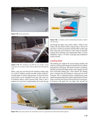
stable for the pilot. Figure 1-76 shows an antiservo tab in Vortex generators are small airfoil sections usually attached
the near neutral position. Deflected in the same direction as to the upper surface of a wing. [Figure 1-78] They are
the desired stabilator movement, it increases the required designed to promote positive laminar airflow over the
control surface input. wing and control surfaces. Usually made of aluminum and
installed in a spanwise line or lines, the vortices created by
Other Wing Features these devices swirl downward assisting maintenance of the
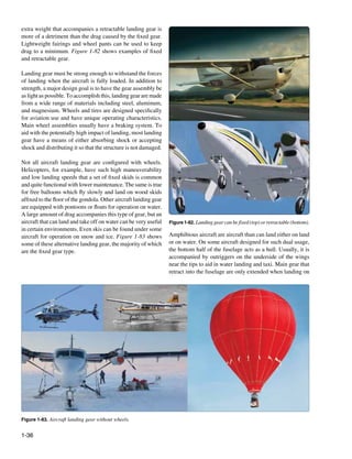
There may be other structures visible on the wings of an boundary layer of air flowing over the wing. They can also
aircraft that contribute to performance. Winglets, vortex be found on the fuselage and empennage. Figure 1-79 shows
generators, stall fences, and gap seals are all common wing the unique vortex generators on a Symphony SA-160 wing.
features. Introductory descriptions of each are given in the
following paragraphs. A chordwise barrier on the upper surface of the wing, called
a stall fence, is used to halt the spanwise flow of air. During
A winglet is an obvious vertical upturn of the wing’s tip low speed flight, this can maintain proper chordwise airflow
resembling a vertical stabilizer. It is an aerodynamic device reducing the tendency for the wing to stall. Usually made
designed to reduce the drag created by wing tip vortices in of aluminum, the fence is a fixed structure most common
flight. Usually made from aluminum or composite materials, on swept wings, which have a natural spanwise tending
winglets can be designed to optimize performance at a desired boundary air flow. [Figure 1-80]
speed. [Figure 1-77]
1-34](https://image.slidesharecdn.com/faa-h-8083-31-amt-airframe-vol-1-130226145854-phpapp01/85/Faa-h-8083-31-amt-airframe-vol-1-60-320.jpg)
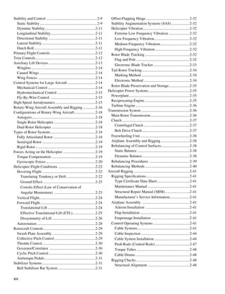
![the ground or a runway. This type of amphibious aircraft is by rigging cables attached to the rudder pedals. Other
sometimes called a flying boat. [Figure 1-84] conventional gear have no tail wheel at all using just a steel
skid plate under the aft fuselage instead. The small tail wheel
or skid plate allows the fuselage to incline, thus giving
clearance for the long propellers that prevailed in aviation
through WWII. It also gives greater clearance between the
propeller and loose debris when operating on an unpaved
runway. But the inclined fuselage blocks the straight ahead
vision of the pilot during ground operations. Until up to speed
where the elevator becomes effective to lift the tail wheel off
the ground, the pilot must lean his head out the side of the
cockpit to see directly ahead of the aircraft.
Figure 1-84. An amphibious aircraft is sometimes called a flying
boat because the fuselage doubles as a hull.
Many aircraft originally designed for land use can be fitted
with floats with retractable wheels for amphibious use.
[Figure 1-85] Typically, the gear retracts into the float
when not needed. Sometimes a dorsal fin is added to the aft
underside of the fuselage for longitudinal stability during
water operations. It is even possible on some aircraft to direct
this type of fin by tying its control into the aircraft’s rudder
pedals. Skis can also be fitted with wheels that retract to allow Figure 1-86. An aircraft with tail wheel gear.
landing on solid ground or on snow and ice.
The use of tail wheel gear can pose another difficulty. When
landing, tail wheel aircraft can easily ground loop. A ground
loop is when the tail of the aircraft swings around and comes
forward of the nose of the aircraft. The reason this happens
is due to the two main wheels being forward of the aircraft’s
center of gravity. The tail wheel is aft of the center of gravity.
If the aircraft swerves upon landing, the tail wheel can swing
out to the side of the intended path of travel. If far enough
to the side, the tail can pull the center of gravity out from its
desired location slightly aft of but between the main gear.
Once the center of gravity is no longer trailing the mains,
the tail of the aircraft freely pivots around the main wheels
causing the ground loop.
Figure 1-85. Retractable wheels make this aircraft amphibious. Conventional gear is useful and is still found on certain models
of aircraft manufactured today, particularly aerobatic aircraft,
Tail Wheel Gear Configuration crop dusters, and aircraft designed for unpaved runway use.
There are two basic configurations of airplane landing gear: It is typically lighter than tricycle gear which requires a stout,
conventional gear or tail wheel gear and the tricycle gear. fully shock absorbing nose wheel assembly. The tail wheel
Tail wheel gear dominated early aviation and therefore configuration excels when operating out of unpaved runways.
has become known as conventional gear. In addition to its With the two strong main gear forward providing stability
two main wheels which are positioned under most of the and directional control during takeoff roll, the lightweight tail
weight of the aircraft, the conventional gear aircraft also wheel does little more than keep the aft end of the fuselage
has a smaller wheel located at the aft end of the fuselage. from striking the ground. As mentioned, at a certain speed,
[Figure 1-86] Often this tail wheel is able to be steered the air flowing over the elevator is sufficient for it to raise the
1-37](https://image.slidesharecdn.com/faa-h-8083-31-amt-airframe-vol-1-130226145854-phpapp01/85/Faa-h-8083-31-amt-airframe-vol-1-63-320.jpg)
![Large aircraft require volumes of maintenance documentation the aircraft from which all fore and aft disances are
t
comprised of thousands of procedures performed by hundreds measured. The distance to a given point is measured
of technicians. Electronic dispatch and recordkeeping of in inches paralel to a center line extending through
l
maintenance performed on large aircraft such as airliners the aircraft from the nose through the center of the
is common. The importance of correct maintenance tail cone. Some manufacturers may call the fuselage
recordkeeping should not be overlooked. station a body staion, abbreviated BS.
t
• Buttock line or butt line (BL) is a vertical reference
Location Numbering Systems
plane down the center of the aircraft from which
Even on small, light aircraft, a method of precisely locating measurements left or right can be made. [Figure 1-89]
each structural component is required. Various numbering
systems are used to facilitate the location of specific wing • Water line (WL) is the measurement of height in
frames, fuselage bulkheads, or any other structural members inches perpendicular from a horizontal plane usually
on an aircraft. Most manufacturers use some system of located at the ground, cabin floor, or some other easily
station marking. For example, the nose of the air raft may be
c referenced location. [Figure 1-90]
designated “zero station,” and all other stations are located at • Aileron station (AS) is measured out oard from,
b
measured distances in inches behind the zero station. Thus, and parallel to, the inboard edge of the aileron,
when a blueprint reads “fuselage frame station 137,” that perpendicular to the rear beam of the wing.
particular frame station can be located 137 inches behind
• Flap station (KS) is measured perpendicular to the rear
the nose of the aircraft.
beam of the wing and parallel to, and outboard from,
the in oard edge of the flap.
b
To locate structures to the right or left of the center line of an
aircraft, a similar method is employed. Many manufacturers • Nacelle station (NC or Nac. Sta.) is measured either
con ider the center line of the aircraft to be a zero station
s forward of or behind the front spar of the wing and
from which measurements can be taken to the right or left perpendic lar to a designated water line.
u
to locate an airframe member. This is often used on the
horizontal stabilizer and wings. In addition to the location stations listed above, other
measurements are used, especially on large aircraft. Thus,
The applicable manufacturer’s numbering system and there may be horizontal stabilizer stations (HSS), vertical
abbreviated designations or symbols should al ays be
w stabilizer stations (VSS) or powerplant stations (PPS).
reviewed before attempting to locate a structural member. [Figure 1-91] In every case, the manufacturer’s terminology
They are not always the same. The following list includes and station lo ation system should be consulted before
c
loca ion designations typical of those used by many
t locating a point on a particular aircraft.
manufacturers.
Another method is used to facilitate the location of aircraft
• Fuselage stations (Fus. Sta. or FS) are numbered in
components on air transport aircraft. This involves dividing
inches from a reference or zero point known as the
the aircraft into zones. These large areas or major zones
reference datum. [Figure 1-88] The reference datum
are further divided into sequentially numbered zones and
is an imaginary verical plane at or near the nose of
t
subzones. The digits of the zone number are reserved and
WL 0.00
FS −97.0
FS −85.20 FS 273.52
FS −80.00 FS 234.00
FS −59.06 FS 224.00
FS −48.50 FS 214.00
FS −31.00 FS 200.70
FS −16.25 FS 189.10
FS 0.00 FS 177.50
FS 20.20 FS 154.75
FS 37.50 FS 132.00
FS 58.75 FS 109.375
FS 69.203 FS 89.25
Figure 1-88. The various body stations relative to a single point of origin illustrated in inches or some other measurement (if of foreign
development).
1-39](https://image.slidesharecdn.com/faa-h-8083-31-amt-airframe-vol-1-130226145854-phpapp01/85/Faa-h-8083-31-amt-airframe-vol-1-65-320.jpg)
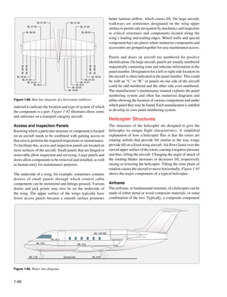
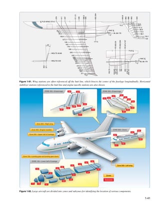

![cooling effect of the air is limited. Approximately 75 percent Transmission
of the incoming airflow is used to cool the engine. The transmission system transfers power from the engine to
the main rotor, tail rotor, and other accessories during normal
The gas turbine engine mounted on most helicopters is flight conditions. The main components of the transmission
made up of a compressor, combustion chamber, turbine, system are the main rotor transmission, tail rotor drive
and accessory gearbox assembly. The compressor draws system, clutch, and freewheeling unit. The freewheeling unit,
filtered air into the plenum chamber and compresses it. or autorotative clutch, allows the main rotor transmission to
Common type filters are centrifugal swirl tubes where debris drive the tail rotor drive shaft during autorotation. Helicopter
is ejected outward and blown overboard prior to entering transmissions are normally lubricated and cooled with their
the compressor, or engine barrier filters (EBF), similar to own oil supply. A sight gauge is provided to check the oil
the K&N filter element used in automotive applications. level. Some transmissions have chip detectors located in the
This design significantly reduces the ingestion of foreign sump. These detectors are wired to warning lights located
object debris (FOD). The compressed air is directed to the on the pilot’s instrument panel that illuminate in the event
combustion section through discharge tubes where atomized of an internal problem. Some chip detectors on modern
fuel is injected into it. The fuel/air mixture is ignited and helicopters have a “burn off” capability and attempt to correct
allowed to expand. This combustion gas is then forced the situation without pilot action. If the problem cannot be
through a series of turbine wheels causing them to turn. corrected on its own, the pilot must refer to the emergency
These turbine wheels provide power to both the engine procedures for that particular helicopter.
compressor and the accessory gearbox. Depending on model
and manufacturer, the rpm range can vary from a range low Main Rotor System
of 20,000 to a range high of 51,600. The rotor system is the rotating part of a helicopter which
generates lift. The rotor consists of a mast, hub, and rotor
Power is provided to the main rotor and tail rotor systems blades. The mast is a cylindrical metal shaft that extends
through the freewheeling unit which is attached to the upwards from and is driven, and sometimes supported, by
accessory gearbox power output gear shaft. The combustion the transmission. At the top of the mast is the attachment
gas is finally expelled through an exhaust outlet. The point for the rotor blades called the hub. The rotor blades are
temperature of gas is measured at different locations and is then attached to the hub by any number of different methods.
referenced differently by each manufacturer. Some common Main rotor systems are classified according to how the main
terms are: inter-turbine temperature (ITT), exhaust gas rotor blades are attached and move relative to the main rotor
temperature (EGT), or turbine outlet temperature (TOT). hub. There are three basic classifications: rigid, semirigid,
TOT is used throughout this discussion for simplicity or fully articulated.
purposes. [Figure 1-94]
Gearbox
Compression Section Turbine Section Combustion Section
Section
Exhaust air outlet N2 Rotor Stator N1 Rotor
Compressor rotor
Igniter plug
Air inlet
Fuel nozzle
Gear
Inlet air
Compressor discharge air Output Shaft
Combustion liner
Combustion gases
Exhaust gases
Figure 1-94. Many helicopters use a turboshaft engine to drive the main transmission and rotor systems. The main difference between
a turboshaft and a turbojet engine is that most of the energy produced by the expanding gases is used to drive a turbine rather than
producing thrust through the expulsion of exhaust gases.
1-43](https://image.slidesharecdn.com/faa-h-8083-31-amt-airframe-vol-1-130226145854-phpapp01/85/Faa-h-8083-31-amt-airframe-vol-1-69-320.jpg)
![Rigid Rotor System the blades to flap up and down. With this hinge, when one
The simplest is the rigid rotor system. In this system, the blade flaps up, the other flaps down.
rotor blades are rigidly attached to the main rotor hub and are
not free to slide back and forth (drag) or move up and down Flapping is caused by a phenomenon known as dissymmetry
(flap). The forces tending to make the rotor blades do so are of lift. As the plane of rotation of the rotor blades is tilted and
absorbed by the flexible properties of the blade. The pitch the helicopter begins to move forward, an advancing blade
of the blades, however, can be adjusted by rotation about and a retreating blade become established (on two-bladed
the spanwise axis via the feathering hinges. [Figure 1-95] systems). The relative windspeed is greater on an advancing
blade than it is on a retreating blade. This causes greater lift
to be developed on the advancing blade, causing it to rise
Static stops
up or flap. When blade rotation reaches the point where the
blade becomes the retreating blade, the extra lift is lost and
the blade flaps downward. [Figure 1-97]
Teetering hinge
Direction of Flight
Retreating Side Advancing Side
a tion
rot
de
a
Bl
Blade tip Blade tip
Relative wind
Relative wind
speed speed
Pitch horn minus plus
helicopter helicopter
speed speed
Feathering hinge
Feathering hinge
(200 knots) (400 knots)
io
n
at
rot
Figure 1-95. The teetering hinge allows the main rotor hub to tilt, and Blade
the feathering hinge enables the pitch angle of the blades to change.
Forward Flight 100 knots
Semirigid Rotor System
Figure 1-97. The blade tip speed of this helicopter is approximately
The semirigid rotor system in Figure 1-96 makes use of a
300 knots. If the helicopter is moving forward at 100 knots, the
teetering hinge at the blade attach point. While held in check
relative windspeed on the advancing side is 400 knots. On the
from sliding back and forth, the teetering hinge does allow
retreating side, it is only 200 knots. This difference in speed causes
a dissymetry of lift.
Coning hinge Teetering hinge
Fully Articulated Rotor System
Blade grip Blade grip
Fully articulated rotor blade systems provide hinges that
allow the rotors to move fore and aft, as well as up and
down. This lead-lag, drag, or hunting movement as it is
called is in response to the Coriolis effect during rotational
Blade pitch
change horn speed changes. When first starting to spin, the blades lag
until centrifugal force is fully developed. Once rotating, a
Pitch link
Coning hinge reduction in speed causes the blades to lead the main rotor
hub until forces come into balance. Constant fluctuations in
rotor blade speeds cause the blades to “hunt.” They are free
Swash plate to do so in a fully articulating system due to being mounted
on the vertical drag hinge.
One or more horizontal hinges provide for flapping on a
fully articulated rotor system. Also, the feathering hinge
allows blade pitch changes by permitting rotation about the
spanwise axis. Various dampers and stops can be found on
Figure 1-96. The semirigid rotor system of the Robinson R22. different designs to reduce shock and limit travel in certain
1-44](https://image.slidesharecdn.com/faa-h-8083-31-amt-airframe-vol-1-130226145854-phpapp01/85/Faa-h-8083-31-amt-airframe-vol-1-70-320.jpg)
![directions. Figure 1-98 shows a fully articulated main rotor
system with the features discussed.
Pitch change axis (feathering)
Pitch horn
Flap hinge Drag hinge
Figure 1-99. Five-blade articulated main rotor with elastomeric bearings.
Damper
by changing the pitch of the tail rotor blades. This, in turn,
changes the amount of countertorque, and the aircraft can be
rotated about its vertical axis, allowing the pilot to control
the direction the helicopter is facing.
Figure 1-98. Fully articulated rotor system.
ation Tor
d e rot qu
Numerous designs and variations on the three types of main Bla e
rotor systems exist. Engineers continually search for ways to
reduce vibration and noise caused by the rotating parts of the
helicopter. Toward that end, the use of elastomeric bearings
in main rotor systems is increasing. These polymer bearings
have the ability to deform and return to their original shape.
As such, they can absorb vibration that would normally be
transferred by steel bearings. They also do not require regular
e
lubrication, which reduces maintenance. Tor
qu
tion
Blade rota
Resultant
Some modern helicopter main rotors have been designed with torque from
Tail rotor thrust
flextures. These are hubs and hub components that are made main rotor
blades
out of advanced composite materials. They are designed to
take up the forces of blade hunting and dissymmetry of lift by
Figure 1-100. A tail rotor is designed to produce thrust in a direction
flexing. As such, many hinges and bearings can be eliminated
from the tradition main rotor system. The result is a simpler opposite to that of the torque produced by the rotation of the main
rotor mast with lower maintenance due to fewer moving rotor blades. It is sometimes called an antitorque rotor.
parts. Often designs using flextures incorporate elastomeric
bearings. [Figure 1-99] Similar to a vertical stabilizer on the empennage of an
airplane, a fin or pylon is also a common feature on rotorcraft.
Antitorque System Normally, it supports the tail rotor assembly, although
Ordinarily, helicopters have between two and seven main some tail rotors are mounted on the tail cone of the boom.
rotor blades. These rotors are usually made of a composite Additionally, a horizontal member called a stabilizer is often
structure. The large rotating mass of the main rotor blades constructed at the tail cone or on the pylon.
of a helicopter produce torque. This torque increases with
engine power and tries to spin the fuselage in the opposite A Fenestron® is a unique tail rotor design which is actually a
direction. The tail boom and tail rotor, or antitorque rotor, multiblade ducted fan mounted in the vertical pylon. It works
counteract this torque effect. [Figure 1-100] Controlled the same way as an ordinary tail rotor, providing sideways
with foot pedals, the countertorque of the tail rotor must be thrust to counter the torque produced by the main rotors.
modulated as engine power levels are changed. This is done [Figure 1-101]
1-45](https://image.slidesharecdn.com/faa-h-8083-31-amt-airframe-vol-1-130226145854-phpapp01/85/Faa-h-8083-31-amt-airframe-vol-1-71-320.jpg)
![Controls
The controls of a helicopter differ slightly from those found
in an aircraft. The collective, operated by the pilot with the
left hand, is pulled up or pushed down to increase or decrease
the angle of attack on all of the rotor blades simultaneously.
This increases or decreases lift and moves the aircraft up
or down. The engine throttle control is located on the hand
grip at the end of the collective. The cyclic is the control
“stick” located between the pilot’s legs. It can be moved in
any direction to tilt the plane of rotation of the rotor blades.
This causes the helicopter to move in the direction that the
cyclic is moved. As stated, the foot pedals control the pitch
of the tail rotor blades thereby balancing main rotor torque.
Figures 1-103 and 1-104 illustrate the controls found in a
Figure 1-101. A Fenestron or “fan-in-tail” antitorque system. typical helicopter.
This design provides an improved margin of safety during ground
operations.
A NOTAR® antitorque system has no visible rotor mounted
on the tail boom. Instead, an engine-driven adjustable fan
is located inside the tail boom. NOTAR® is an acronym
that stands for “no tail rotor.” As the speed of the main
rotor changes, the speed of the NOTAR® fan changes. Air Throttle control
is vented out of two long slots on the right side of the tail
boom, entraining main rotor wash to hug the right side of the
tail boom, in turn causing laminar flow and a low pressure
(Coanda Effect). This low pressure causes a force counter
to the torque produced by the main rotor. Additionally, the
remainder of the air from the fan is sent through the tail
boom to a vent on the aft left side of the boom where it is
expelled. This action to the left causes an opposite reaction Collective
to the right, which is the direction needed to counter the main
rotor torque. [Figures 1-102] Figure 1-103. The collective changes the pitch of all of the rotor
blades simultaneously and by the same amount, thereby increasing
or decreasing lift.
Downwash
Air jet
Main rotor wake Lift
Air intake
Rotating nozzle
Figure 1-102. While in a hover, Coanda Effect supplies
approximately two-thirds of the lift necessary to maintain
directional control. The rest is created by directing the thrust from
the controllable rotating nozzle.
1-46](https://image.slidesharecdn.com/faa-h-8083-31-amt-airframe-vol-1-130226145854-phpapp01/85/Faa-h-8083-31-amt-airframe-vol-1-72-320.jpg)
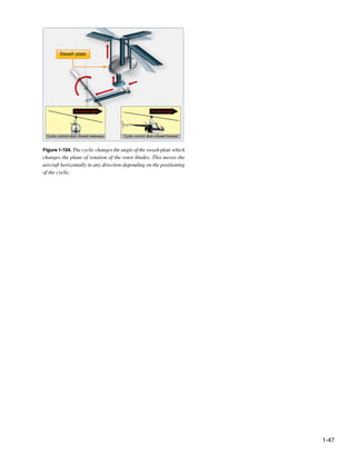

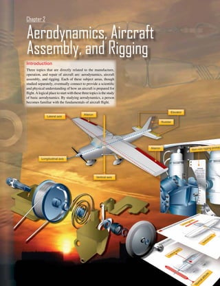
![Basic Aerodynamics the definition of a substance that has the ability to flow or
assume the shape of the container in which it is enclosed.
Aerodynamics is the study of the dynamics of gases, the
If the container is heated, pressure increases; if cooled, the
interaction between a moving object and the atmosphere
pressure decreases. The weight of air is heaviest at sea level
being of primary interest for this handbook. The movement of
where it has been compressed by all of the air above. This
an object and its reaction to the air flow around it can be seen
compression of air is called atmospheric pressure.
when watching water passing the bow of a ship. The major
difference between water and air is that air is compressible
Pressure
and water is incompressible. The action of the airflow over
Atmospheric pressure is usually defined as the force exerted
a body is a large part of the study of aerodynamics. Some
against the earth’s surface by the weight of the air above
common aircraft terms, such as rudder, hull, water line, and
that surface. Weight is force applied to an area that results
keel beam, were borrowed from nautical terms.
in pressure. Force (F) equals area (A) times pressure (P), or
F = AP. Therefore, to find the amount of pressure, divide
Many textbooks have been written about the aerodynamics
area into force (P = F/A). A column of air (one square inch)
of aircraft flight. It is not necessary for an airframe and
extending from sea level to the top of the atmosphere weighs
powerplant (A&P) mechanic to be as knowledgeable as an
approximately 14.7 pounds; therefore, atmospheric pressure
aeronautical engineer about aerodynamics. The mechanic
is stated in pounds per square inch (psi). Thus, atmospheric
must be able to understand the relationships between
pressure at sea level is 14.7 psi.
how an aircraft performs in flight and its reaction to the
forces acting on its structural parts. Understanding why
Atmospheric pressure is measured with an instrument
aircraft are designed with particular types of primary and
called a barometer, composed of mercury in a tube that
secondary control systems and why the surfaces must be
records atmospheric pressure in inches of mercury ("Hg).
aerodynamically smooth becomes essential when maintaining
[Figure 2-1] The standard measurement in aviation altimeters
today’s complex aircraft.
and U.S. weather reports has been "Hg. However, world-wide
weather maps and some non-U.S. manufactured aircraft
The theory of flight should be described in terms of the laws
instruments indicate pressure in millibars (mb), a metric unit.
of flight because what happens to an aircraft when it flies
is not based upon assumptions, but upon a series of facts.
Aerodynamics is a study of laws which have been proven
to be the physical reasons why an airplane flies. The term Vacuum
Inches of
aerodynamics is derived from the combination of two Greek Standard Mercury
Millibars Standard
Sea Level Sea Level
words: “aero,” meaning air, and “dyne,” meaning force of Pressure 30 1016 Pressure
power. Thus, when “aero” joins “dynamics” the result is 29.92"Hg 25 847 1013 mb
“aerodynamics”—the study of objects in motion through 20 677
the air and the forces that produce or change such motion. 15 508
10 339
Aerodynamically, an aircraft can be defined as an object
5 170
traveling through space that is affected by the changes Atmospheric Pressure
0 0
in atmospheric conditions. To state it another way,
aerodynamics covers the relationships between the aircraft,
relative wind, and atmosphere.
1"
The Atmosphere 1"
Before examining the fundamental laws of flight, several
basic facts must be considered, namely that an aircraft
1"
operates in the air. Therefore, those properties of air that 0.491 lb Mercury
affect the control and performance of an aircraft must be
understood. Figure 2-1. Barometer used to measure atmospheric pressure.
The air in the earth’s atmosphere is composed mostly of
nitrogen and oxygen. Air is considered a fluid because it fits
2-2](https://image.slidesharecdn.com/faa-h-8083-31-amt-airframe-vol-1-130226145854-phpapp01/85/Faa-h-8083-31-amt-airframe-vol-1-76-320.jpg)
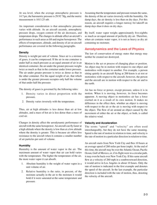
![Acceleration is defined as the rate of change of velocity. If an aircraft is flying against a headwind, it is slowed down.
An aircraft increasing in velocity is an example of positive If the wind is coming from either side of the aircraft’s
acceleration, while another aircraft reducing its velocity is an heading, the aircraft is pushed off course unless the pilot
example of negative acceleration, or deceleration. takes corrective action against the wind direction.
Newton’s Laws of Motion Newton’s third law is the law of action and reaction. This
The fundamental laws governing the action of air about a law states that for every action (force) there is an equal
wing are known as Newton’s laws of motion. and opposite reaction (force). This law can be illustrated
by the example of firing a gun. The action is the forward
Newton’s first law is normally referred to as the law of movement of the bullet while the reaction is the backward
inertia. It simply means that a body at rest does not move recoil of the gun.
unless force is applied to it. If a body is moving at uniform
speed in a straight line, force must be applied to increase or The three laws of motion that have been discussed apply to
decrease the speed. the theory of flight. In many cases, all three laws may be
operating on an aircraft at the same time.
According to Newton’s law, since air has mass, it is a body.
When an aircraft is on the ground with its engines off, inertia Bernoulli’s Principle and Subsonic Flow
keeps the aircraft at rest. An aircraft is moved from its state Bernoulli’s principle states that when a fluid (air) flowing
of rest by the thrust force created by a propeller, or by the through a tube reaches a constriction, or narrowing, of the
expanding exhaust, or both. When an aircraft is flying at tube, the speed of the fluid flowing through that constriction
uniform speed in a straight line, inertia tends to keep the is increased and its pressure is decreased. The cambered
aircraft moving. Some external force is required to change (curved) surface of an airfoil (wing) affects the airflow
the aircraft from its path of flight. exactly as a constriction in a tube affects airflow. [Figure 2-2]
Diagram A of Figure 2-2 illustrates the effect of air passing
Newton’s second law states that if a body moving with through a constriction in a tube. In B, air is flowing past a
uniform speed is acted upon by an external force, the change cambered surface, such as an airfoil, and the effect is similar
of motion is proportional to the amount of the force, and to that of air passing through a restriction.
motion takes place in the direction in which the force acts.
This law may be stated mathematically as follows:
Force = mass × acceleration (F = ma)
A Mass of air
Same
mass of air
Velocity increased
Normal pressure Pressure decreased Normal pressure
(Compared to original)
B
Normal flow Increased flow Normal flow
Figure 2-2. Bernoulli’s Principle.
2-4](https://image.slidesharecdn.com/faa-h-8083-31-amt-airframe-vol-1-130226145854-phpapp01/85/Faa-h-8083-31-amt-airframe-vol-1-78-320.jpg)
![As the air flows over the upper surface of an airfoil, its Shape of the Airfoil
velocity increases and its pressure decreases; an area of low Individual airfoil section properties differ from those
pressure is formed. There is an area of greater pressure on properties of the wing or aircraft as a whole because of the
the lower surface of the airfoil, and this greater pressure effect of the wing planform. A wing may have various airfoil
tends to move the wing upward. The difference in pressure sections from root to tip, with taper, twist, and sweepback.
between the upper and lower surfaces of the wing is called The resulting aerodynamic properties of the wing are
lift. Three-fourths of the total lift of an airfoil is the result of determined by the action of each section along the span.
the decrease in pressure over the upper surface. The impact
of air on the under surface of an airfoil produces the other The shape of the airfoil determines the amount of turbulence
one-fourth of the total lift. or skin friction that it produces, consequently affecting the
efficiency of the wing. Turbulence and skin friction are
Airfoil controlled mainly by the fineness ratio, which is defined as
An airfoil is a surface designed to obtain lift from the air the ratio of the chord of the airfoil to the maximum thickness.
through which it moves. Thus, it can be stated that any part If the wing has a high fineness ratio, it is a very thin wing.
of the aircraft that converts air resistance into lift is an airfoil. A thick wing has a low fineness ratio. A wing with a high
The profile of a conventional wing is an excellent example fineness ratio produces a large amount of skin friction. A
of an airfoil. [Figure 2-3] Notice that the top surface of the wing with a low fineness ratio produces a large amount of
wing profile has greater curvature than the lower surface. turbulence. The best wing is a compromise between these
two extremes to hold both turbulence and skin friction to a
minimum.
115 mph 14.54 lb/in2
The efficiency of a wing is measured in terms of the lift to
drag ratio (L/D). This ratio varies with the AOA but reaches a
definite maximum value for a particular AOA. At this angle,
the wing has reached its maximum efficiency. The shape of
the airfoil is the factor that determines the AOA at which
100 mph 14.7 lb/in2 105 mph 14.67 lb/in2 the wing is most efficient; it also determines the degree of
efficiency. Research has shown that the most efficient airfoils
Figure 2-3. Airflow over a wing section. for general use have the maximum thickness occurring about
one-third of the way back from the leading edge of the wing.
The difference in curvature of the upper and lower surfaces
of the wing builds up the lift force. Air flowing over the top High-lift wings and high-lift devices for wings have been
surface of the wing must reach the trailing edge of the wing developed by shaping the airfoils to produce the desired
in the same amount of time as the air flowing under the wing. effect. The amount of lift produced by an airfoil increases
To do this, the air passing over the top surface moves at a with an increase in wing camber. Camber refers to the
greater velocity than the air passing below the wing because curvature of an airfoil above and below the chord line surface.
of the greater distance it must travel along the top surface. Upper camber refers to the upper surface, lower camber to
This increased velocity, according to Bernoulli’s Principle, the lower surface, and mean camber to the mean line of the
means a corresponding decrease in pressure on the surface. section. Camber is positive when departure from the chord
Thus, a pressure differential is created between the upper line is outward and negative when it is inward. Thus, high-lift
and lower surfaces of the wing, forcing the wing upward in wings have a large positive camber on the upper surface and
the direction of the lower pressure. a slightly negative camber on the lower surface. Wing flaps
cause an ordinary wing to approximate this same condition
Within limits, lift can be increased by increasing the angle by increasing the upper camber and by creating a negative
of attack (AOA), wing area, velocity, density of the air, or lower camber.
by changing the shape of the airfoil. When the force of lift
on an aircraft’s wing equals the force of gravity, the aircraft
maintains level flight.
2-5](https://image.slidesharecdn.com/faa-h-8083-31-amt-airframe-vol-1-130226145854-phpapp01/85/Faa-h-8083-31-amt-airframe-vol-1-79-320.jpg)
![It is also known that the larger the wingspan, as compared
to the chord, the greater the lift obtained. This comparison Angle of attack
is called aspect ratio. The higher the aspect ratio, the greater Resultant lift
Cho
the lift. In spite of the benefits from an increase in aspect rd li
ne Lift
ratio, it was found that definite limitations were defined by
structural and drag considerations. Relative airstream Drag
On the other hand, an airfoil that is perfectly streamlined Center of pressure
and offers little wind resistance sometimes does not have
enough lifting power to take the aircraft off the ground. Thus, Figure 2-5. Airflow over a wing section.
modern aircraft have airfoils which strike a medium between
extremes, the shape depending on the purposes of the aircraft On each part of an airfoil or wing surface, a small force is
for which it is designed. present. This force is of a different magnitude and direction
from any forces acting on other areas forward or rearward
Angle of Incidence from this point. It is possible to add all of these small forces
The acute angle the wing chord makes with the longitudinal mathematically. That sum is called the “resultant force”
axis of the aircraft is called the angle of incidence, or the angle (lift). This resultant force has magnitude, direction, and
of wing setting. [Figure 2-4] The angle of incidence in most location, and can be represented as a vector, as shown in
cases is a fixed, built-in angle. When the leading edge of the Figure 2-5. The point of intersection of the resultant force
wing is higher than the trailing edge, the angle of incidence is line with the chord line of the airfoil is called the center of
said to be positive. The angle of incidence is negative when pressure (CP). The CP moves along the airfoil chord as the
the leading edge is lower than the trailing edge of the wing. AOA changes. Throughout most of the flight range, the CP
moves forward with increasing AOA and rearward as the
AOA decreases. The effect of increasing AOA on the CP is
Angle of incidence shown in Figure 2-6.
Longitudinal axis The AOA changes as the aircraft’s attitude changes. Since the
AOA has a great deal to do with determining lift, it is given
Chord line primary consideration when designing airfoils. In a properly
of wing
designed airfoil, the lift increases as the AOA is increased.
When the AOA is increased gradually toward a positive
Figure 2-4. Angle of incidence. AOA, the lift component increases rapidly up to a certain
point and then suddenly begins to drop off. During this action
the drag component increases slowly at first, then rapidly as
Angle of Attack (AOA) lift begins to drop off.
Before beginning the discussion on AOA and its effect on
airfoils, first consider the terms chord and center of pressure When the AOA increases to the angle of maximum lift, the
(CP) as illustrated in Figure 2-5. burble point is reached. This is known as the critical angle.
When the critical angle is reached, the air ceases to flow
The chord of an airfoil or wing section is an imaginary smoothly over the top surface of the airfoil and begins to
straight line that passes through the section from the leading burble or eddy. This means that air breaks away from the
edge to the trailing edge, as shown in Figure 2-5. The chord upper camber line of the wing. What was formerly the area
line provides one side of an angle that ultimately forms of decreased pressure is now filled by this burbling air.
the AOA. The other side of the angle is formed by a line When this occurs, the amount of lift drops and drag becomes
indicating the direction of the relative airstream. Thus, AOA excessive. The force of gravity exerts itself, and the nose of
is defined as the angle between the chord line of the wing and the aircraft drops. This is a stall. Thus, the burble point is
the direction of the relative wind. This is not to be confused the stalling angle.
with the angle of incidence, illustrated in Figure 2-4, which
is the angle between the chord line of the wing and the
longitudinal axis of the aircraft.
2-6](https://image.slidesharecdn.com/faa-h-8083-31-amt-airframe-vol-1-130226145854-phpapp01/85/Faa-h-8083-31-amt-airframe-vol-1-80-320.jpg)
![A Angle of attack = 0°
Thrust and Drag
Resultant An aircraft in flight is the center of a continuous battle of
Negative pressure pattern forces. Actually, this conflict is not as violent as it sounds,
Relative airstream
but it is the key to all maneuvers performed in the air. There
is nothing mysterious about these forces; they are definite and
known. The directions in which they act can be calculated,
and the aircraft itself is designed to take advantage of each
Positive pressure Center of pressure of them. In all types of flying, flight calculations are based
on the magnitude and direction of four forces: weight, lift,
B Angle of attack = 6° drag, and thrust. [Figure 2-7]
Resultant Negative pressure pattern
moves forward
Lift
Relative airstream
Positive pressure Drag
Thrust
C Angle of attack = 12°
Resultant
Center of pressure
moves forward
Weight
Relative airstream
Positive pressure
u Figure 2-7. Forces in action during flight.
D Angle of attack = 18°
An aircraft in flight is acted upon by four forces:
Wing completely stalled 1. Gravity or weight—the force that pulls the aircraft
toward the earth. Weight is the force of gravity acting
downward upon everything that goes into the aircraft,
such as the aircraft itself, crew, fuel, and cargo.
Positive pressure
2. Lift—the force that pushes the aircraft upward. Lift
acts vertically and counteracts the effects of weight.
Figure 2-6. Effect on increasing angle of attack. 3. Thrust—the force that moves the aircraft forward.
Thrust is the forward force produced by the powerplant
As previously seen, the distribution of the pressure forces that overcomes the force of drag.
over the airfoil varies with the AOA. The application of the
resultant force, or CP, varies correspondingly. As this angle 3. Drag—the force that exerts a braking action to hold
increases, the CP moves forward; as the angle decreases, the the aircraft back. Drag is a backward deterrent force
CP moves back. The unstable travel of the CP is characteristic and is caused by the disruption of the airflow by the
of almost all airfoils. wings, fuselage, and protruding objects.
Boundary Layer These four forces are in perfect balance only when the aircraft
In the study of physics and fluid mechanics, a boundary layer is in straight-and-level unaccelerated flight.
is that layer of fluid in the immediate vicinity of a bounding
surface. In relation to an aircraft, the boundary layer is the The forces of lift and drag are the direct result of the
part of the airflow closest to the surface of the aircraft. In relationship between the relative wind and the aircraft. The
designing high-performance aircraft, considerable attention force of lift always acts perpendicular to the relative wind,
is paid to controlling the behavior of the boundary layer to and the force of drag always acts parallel to and in the same
minimize pressure drag and skin friction drag. direction as the relative wind. These forces are actually the
components that produce a resultant lift force on the wing.
[Figure 2-8]
2-7](https://image.slidesharecdn.com/faa-h-8083-31-amt-airframe-vol-1-130226145854-phpapp01/85/Faa-h-8083-31-amt-airframe-vol-1-81-320.jpg)
![drag are equal. In order to maintain a steady speed, thrust and
Resultant drag must remain equal, just as lift and weight must be equal
for steady, horizontal flight. Increasing the lift means that the
Lift
aircraft moves upward, whereas decreasing the lift so that it
is less than the weight causes the aircraft to lose altitude. A
similar rule applies to the two forces of thrust and drag. If
the revolutions per minute (rpm) of the engine is reduced, the
Drag thrust is lessened, and the aircraft slows down. As long as the
thrust is less than the drag, the aircraft travels more and more
slowly until its speed is insufficient to support it in the air.
Figure 2-8. Resultant of lift and drag. Likewise, if the rpm of the engine is increased, thrust becomes
Weight has a definite relationship with lift, and thrust with greater than drag, and the speed of the aircraft increases. As
drag. These relationships are quite simple, but very important long as the thrust continues to be greater than the drag, the
in understanding the aerodynamics of flying. As stated aircraft continues to accelerate. When drag equals thrust, the
previously, lift is the upward force on the wing perpendicular aircraft flies at a steady speed.
to the relative wind. Lift is required to counteract the aircraft’s
weight, caused by the force of gravity acting on the mass of The relative motion of the air over an object that produces
the aircraft. This weight force acts downward through a point lift also produces drag. Drag is the resistance of the air to
called the center of gravity (CG). The CG is the point at which objects moving through it. If an aircraft is flying on a level
all the weight of the aircraft is considered to be concentrated. course, the lift force acts vertically to support it while the
When the lift force is in equilibrium with the weight force, drag force acts horizontally to hold it back. The total amount
the aircraft neither gains nor loses altitude. If lift becomes of drag on an aircraft is made up of many drag forces, but
less than weight, the aircraft loses altitude. When the lift is this handbook considers three: parasite drag, profile drag,
greater than the weight, the aircraft gains altitude. and induced drag.
Wing area is measured in square feet and includes the Parasite drag is made up of a combination of many different
part blanked out by the fuselage. Wing area is adequately drag forces. Any exposed object on an aircraft offers some
described as the area of the shadow cast by the wing at high resistance to the air, and the more objects in the airstream,
noon. Tests show that lift and drag forces acting on a wing the more parasite drag. While parasite drag can be reduced
are roughly proportional to the wing area. This means that by reducing the number of exposed parts to as few as
if the wing area is doubled, all other variables remaining the practical and streamlining their shape, skin friction is the
same, the lift and drag created by the wing is doubled. If the type of parasite drag most difficult to reduce. No surface is
area is tripled, lift and drag are tripled. perfectly smooth. Even machined surfaces have a ragged
uneven appearance when inspected under magnification.
Drag must be overcome for the aircraft to move, and These ragged surfaces deflect the air near the surface causing
movement is essential to obtain lift. To overcome drag and resistance to smooth airflow. Skin friction can be reduced by
move the aircraft forward, another force is essential. This using glossy smooth finishes and eliminating protruding rivet
force is thrust. Thrust is derived from jet propulsion or from heads, roughness, and other irregularities.
a propeller and engine combination. Jet propulsion theory
is based on Newton’s third law of motion (page 2-4). The Profile drag may be considered the parasite drag of the airfoil.
turbine engine causes a mass of air to be moved backward The various components of parasite drag are all of the same
at high velocity causing a reaction that moves the aircraft nature as profile drag.
forward.
The action of the airfoil that creates lift also causes induced
In a propeller/engine combination, the propeller is actually drag. Remember, the pressure above the wing is less than
two or more revolving airfoils mounted on a horizontal shaft. atmospheric pressure, and the pressure below the wing is
The motion of the blades through the air produces lift similar equal to or greater than atmospheric pressure. Since fluids
to the lift on the wing, but acts in a horizontal direction, always move from high pressure toward low pressure, there
pulling the aircraft forward. is a spanwise movement of air from the bottom of the wing
outward from the fuselage and upward around the wing tip.
Before the aircraft begins to move, thrust must be exerted. This flow of air results in spillage over the wing tip, thereby
The aircraft continues to move and gain speed until thrust and setting up a whirlpool of air called a “vortex.” [Figure 2-9]
2-8](https://image.slidesharecdn.com/faa-h-8083-31-amt-airframe-vol-1-130226145854-phpapp01/85/Faa-h-8083-31-amt-airframe-vol-1-82-320.jpg)
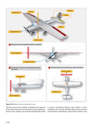
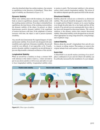
![Primary Flight Controls Balance tabs are designed to move in the opposite direction
of the primary flight control. Thus, aerodynamic forces acting
The primary controls are the ailerons, elevator, and the
on the tab assist in moving the primary control surface.
rudder, which provide the aerodynamic force to make the
aircraft follow a desired flightpath. [Figure 2-10] The flight
Spring tabs are similar in appearance to trim tabs, but serve an
control surfaces are hinged or movable airfoils designed to
entirely different purpose. Spring tabs are used for the same
change the attitude of the aircraft by changing the airflow
purpose as hydraulic actuators—to aid the pilot in moving
over the aircraft’s surface during flight. These surfaces are
the primary control surface.
used for moving the aircraft about its three axes.
Figure 2-13 indicates how each trim tab is hinged to its parent
Typically, the ailerons and elevators are operated from the
primary control surface, but is operated by an independent
flight deck by means of a control stick, a wheel, and yoke
control.
assembly and on some of the newer design aircraft, a joy-
stick. The rudder is normally operated by foot pedals on most
aircraft. Lateral control is the banking movement or roll of an Control horn
aircraft that is controlled by the ailerons. Longitudinal control
is the climb and dive movement or pitch of an aircraft that Tab
Fixed surface
is controlled by the elevator. Directional control is the left
and right movement or yaw of an aircraft that is controlled
by the rudder. Control surface
Trim tab
Trim Controls
Horn free to pivot on hinge axis
Included in the trim controls are the trim tabs, servo tabs,
balance tabs, and spring tabs. Trim tabs are small airfoils
recessed into the trailing edges of the primary control
surfaces. [Figure 2-12] Trim tabs can be used to correct any
tendency of the aircraft to move toward an undesirable flight
attitude. Their purpose is to enable the pilot to trim out any
Servo tab
unbalanced condition which may exist during flight, without
exerting any pressure on the primary controls. Control horn
Trim tabs
Balance tab
Control horn
Spring cartridge
Spring tab
Figure 2-13. Types of trim tabs.
Figure 2-12. Trim tabs.
Servo tabs, sometimes referred to as flight tabs, are used
primarily on the large main control surfaces. They aid in
moving the main control surface and holding it in the desired
position. Only the servo tab moves in response to movement
by the pilot of the primary flight controls.
2-12](https://image.slidesharecdn.com/faa-h-8083-31-amt-airframe-vol-1-130226145854-phpapp01/85/Faa-h-8083-31-amt-airframe-vol-1-86-320.jpg)
![Auxiliary Lift Devices
Included in the auxiliary lift devices group of flight control
surfaces are the wing flaps, spoilers, speed brakes, slats,
leading edge flaps, and slots.
The auxiliary groups may be divided into two subgroups: Basic section
those whose primary purpose is lift augmenting and those
whose primary purpose is lift decreasing. In the first group are
the flaps, both trailing edge and leading edge (slats), and slots.
The lift decreasing devices are speed brakes and spoilers.
The trailing edge airfoils (flaps) increase the wing area,
Plain flap
thereby increasing lift on takeoff, and decrease the speed
during landing. These airfoils are retractable and fair into
the wing contour. Others are simply a portion of the lower
skin which extends into the airstream, thereby slowing the
aircraft. Leading edge flaps are airfoils extended from and
retracted into the leading edge of the wing. Some installations
create a slot (an opening between the extended airfoil and the Split flap
leading edge). The flap (termed slat by some manufacturers)
and slot create additional lift at the lower speeds of takeoff
and landing. [Figure 2-14]
Other installations have permanent slots built in the leading
edge of the wing. At cruising speeds, the trailing edge
Slotted flap
and leading edge flaps (slats) are retracted into the wing
proper. Slats are movable control surfaces attached to the
leading edges of the wings. When the slat is closed, it forms
the leading edge of the wing. When in the open position
(extended forward), a slot is created between the slat and the
wing leading edge. At low airspeeds, this increases lift and
improves handling characteristics, allowing the aircraft to Fowler flap
be controlled at airspeeds below the normal landing speed.
[Figure 2-15]
Lift decreasing devices are the speed brakes (spoilers). In
some installations, there are two types of spoilers. The ground
spoiler is extended only after the aircraft is on the ground,
Slotted Fowler flap
thereby assisting in the braking action. The flight spoiler
assists in lateral control by being extended whenever the
aileron on that wing is rotated up. When actuated as speed Figure 2-14. Types of wing flaps.
brakes, the spoiler panels on both wings raise up. In-flight
spoilers may also be located along the sides, underneath the
fuselage, or back at the tail. [Figure 2-16] In some aircraft
designs, the wing panel on the up aileron side rises more than
the wing panel on the down aileron side. This provides speed
Fixed slot
brake operation and lateral control simultaneously.
Slat
Automatic slot
Figure 2-15. Wing slots.
2-13](https://image.slidesharecdn.com/faa-h-8083-31-amt-airframe-vol-1-130226145854-phpapp01/85/Faa-h-8083-31-amt-airframe-vol-1-87-320.jpg)
![Figure 2-19. The Beechcraft 2000 Starship has canard wings.
Figure 2-16. Speed brake. Wing Fences
Wing fences are flat metal vertical plates fixed to the upper
Winglets
surface of the wing. They obstruct spanwise airflow along
Winglets are the near-vertical extension of the wingtip
the wing, and prevent the entire wing from stalling at once.
that reduces the aerodynamic drag associated with vortices
They are often attached on swept-wing aircraft to prevent
that develop at the wingtips as the airplane moves through
the spanwise movement of air at high angles of attack. Their
the air. By reducing the induced drag at the tips of the
purpose is to provide better slow speed handling and stall
wings, fuel consumption goes down and range is extended.
characteristics. [Figure 2-20]
Figure 2-17 Shows an example of a Boeing 737 with winglets.
Figure 2-17. Winglets on a Bombardier Learjet 60.
Canard Wings
A canard wing aircraft is an airframe configuration of a fixed- Figure 2-20. Aircraft stall fence.
wing aircraft in which a small wing or horizontal airfoil is
ahead of the main lifting surfaces, rather than behind them as Control Systems for Large Aircraft
in a conventional aircraft. The canard may be fixed, movable,
Mechanical Control
or designed with elevators. Good examples of aircraft with
This is the basic type of system that was used to control
canard wings are the Rutan VariEze and Beechcraft 2000
early aircraft and is currently used in smaller aircraft where
Starship. [Figures 2-18 and 2-19]
aerodynamic forces are not excessive. The controls are
mechanical and manually operated.
The mechanical system of controlling an aircraft can include
cables, push-pull tubes, and torque tubes. The cable system
is the most widely used because deflections of the structure
to which it is attached do not affect its operation. Some
aircraft incorporate control systems that are a combination
of all three. These systems incorporate cable assemblies,
Figure 2-18. Canard wings on a Rutan VariEze.
2-14](https://image.slidesharecdn.com/faa-h-8083-31-amt-airframe-vol-1-130226145854-phpapp01/85/Faa-h-8083-31-amt-airframe-vol-1-88-320.jpg)
![cable guides, linkage, adjustable stops, and control surface Many of the new military high-performance aircraft are not
snubber or mechanical locking devices. These surface locking aerodynamically stable. This characteristic is designed into
devices, usually referred to as a gust lock, limits the external the aircraft for increased maneuverability and responsive
wind forces from damaging the aircraft while it is parked or performance. Without the computers reacting to the
tied down. instability, the pilot would lose control of the aircraft.
Hydromechanical Control The Airbus A-320 was the first commercial airliner to use
As the size, complexity, and speed of aircraft increased, FBW controls. Boeing used them in their 777 and newer
actuation of controls in flight became more difficult. It soon design commercial aircraft. The Dassault Falcon 7X was the
became apparent that the pilot needed assistance to overcome first business jet to use a FBW control system.
the aerodynamic forces to control aircraft movement. Spring
tabs, which were operated by the conventional control High-Speed Aerodynamics
system, were moved so that the airflow over them actually High-speed aerodynamics, often called compressible
moved the primary control surface. This was sufficient aerodynamics, is a special branch of study of aeronautics.
for the aircraft operating in the lowest of the high speed It is utilized by aircraft designers when designing aircraft
ranges (250–300 mph). For higher speeds, a power-assisted capable of speeds approaching Mach 1 and above. Because
(hydraulic) control system was designed. it is beyond the scope and intent of this handbook, only a
brief overview of the subject is provided.
Conventional cable or push-pull tube systems link the flight
deck controls with the hydraulic system. With the system In the study of high-speed aeronautics, the compressibility
activated, the pilot’s movement of a control causes the effects on air must be addressed. This flight regime is
mechanical link to open servo valves, thereby directing characterized by the Mach number, a special parameter
hydraulic fluid to actuators, which convert hydraulic pressure named in honor of Ernst Mach, the late 19th century physicist
into control surface movements. who studied gas dynamics. Mach number is the ratio of
the speed of the aircraft to the local speed of sound and
Because of the efficiency of the hydromechanical flight determines the magnitude of many of the compressibility
control system, the aerodynamic forces on the control effects.
surfaces cannot be felt by the pilot, and there is a risk of
overstressing the structure of the aircraft. To overcome As an aircraft moves through the air, the air molecules near
this problem, aircraft designers incorporated artificial feel the aircraft are disturbed and move around the aircraft. The
systems into the design that provided increased resistance air molecules are pushed aside much like a boat creates a bow
to the controls at higher speeds. Additionally, some aircraft wave as it moves through the water. If the aircraft passes at a
with hydraulically powered control systems are fitted with low speed, typically less than 250 mph, the density of the air
a device called a stick shaker, which provides an artificial remains constant. But at higher speeds, some of the energy of
stall warning to the pilot. the aircraft goes into compressing the air and locally changing
the density of the air. The bigger and heavier the aircraft, the
Fly-By-Wire Control more air it displaces and the greater effect compression has
The fly-by-wire (FBW) control system employs electrical on the aircraft.
signals that transmit the pilot’s actions from the flight deck
through a computer to the various flight control actuators. This effect becomes more important as speed increases. Near
The FBW system evolved as a way to reduce the system and beyond the speed of sound, about 760 mph (at sea level),
weight of the hydromechanical system, reduce maintenance sharp disturbances generate a shockwave that affects both the
costs, and improve reliability. Electronic FBW control lift and drag of an aircraft and flow conditions downstream of
systems can respond to changing aerodynamic conditions the shockwave. The shockwave forms a cone of pressurized
by adjusting flight control movements so that the aircraft air molecules which move outward and rearward in all
response is consistent for all flight conditions. Additionally, directions and extend to the ground. The sharp release of the
the computers can be programmed to prevent undesirable pressure, after the buildup by the shockwave, is heard as the
and dangerous characteristics, such as stalling and spinning. sonic boom. [Figure 2-21]
2-15](https://image.slidesharecdn.com/faa-h-8083-31-amt-airframe-vol-1-130226145854-phpapp01/85/Faa-h-8083-31-amt-airframe-vol-1-89-320.jpg)
![Additional technical information pertaining to high-speed
aerodynamics can be found at bookstores, libraries, and
numerous sources on the Internet. As the design of aircraft
evolves and the speeds of aircraft continue to increase into
the hypersonic range, new materials and propulsion systems
will need to be developed. This is the challenge for engineers,
physicists, and designers of aircraft in the future.
Rotary-Wing Aircraft Assembly and
Rigging
The flight control units located in the flight deck of all
helicopters are very nearly the same. All helicopters have
either one or two of each of the following: collective pitch
Figure 2-21. Breaking the sound barrier. control, throttle grip, cyclic pitch control, and directional
control pedals. [Figure 2-22] Basically, these units do the
Listed below are a range of conditions that are encountered same things, regardless of the type of helicopter on which
by aircraft as their designed speed increases. they are installed; however, the operation of the control
• Subsonic conditions occur for Mach numbers less system varies greatly by helicopter model.
than one (100–350 mph). For the lowest subsonic
conditions, compressibility can be ignored. Rigging the helicopter coordinates the movements of the
• As the speed of the object approaches the speed flight controls and establishes the relationship between the
of sound, the flight Mach number is nearly equal main rotor and its controls, and between the tail rotor and its
to one, M = 1 (350–760 mph), and the flow is said controls. Rigging is not a difficult job, but it requires great
to be transonic. At some locations on the object, precision and attention to detail. Strict adherence to rigging
the local speed of air exceeds the speed of sound. procedures described in the manufacturer’s maintenance
Compressibility effects are most important in manuals and service instructions is a must. Adjustments,
transonic flows and lead to the early belief in a sound clearances, and tolerances must be exact.
barrier. Flight faster than sound was thought to be
impossible. In fact, the sound barrier was only an Rigging of the various flight control systems can be broken
increase in the drag near sonic conditions because down into the following three major steps:
of compressibility effects. Because of the high drag 1. Placing the control system in a specific position—
associated with compressibility effects, aircraft are holding it in position with pins, clamps, or jigs, then
not operated in cruise conditions near Mach 1. adjusting the various linkages to fit the immobilized
• Supersonic conditions occur for numbers greater control component.
than Mach 1, but less then Mach 3 (760–2,280 2. Placing the control surfaces in a specific reference
mph). Compressibility effects of gas are important position—using a rigging jig, a precision bubble
in the design of supersonic aircraft because of the protractor, or a spirit level to check the angular
shockwaves that are generated by the surface of the difference between the control surface and some fixed
object. For high supersonic speeds, between Mach 3 surface on the aircraft. [Figure 2-23]
and Mach 5 (2,280–3,600 mph), aerodynamic heating 3. Setting the maximum range of travel of the various
becomes a very important factor in aircraft design. components—this adjustment limits the physical
• For speeds greater than Mach 5, the flow is said to movement of the control system.
be hypersonic. At these speeds, some of the energy
of the object now goes into exciting the chemical After completion of the static rigging, a functional check of
bonds which hold together the nitrogen and oxygen the flight control system must be accomplished. The nature
molecules of the air. At hypersonic speeds, the of the functional check varies with the type of helicopter and
chemistry of the air must be considered when system concerned, but usually includes determining that:
determining forces on the object. When the Space 1. The direction of movement of the main and tail rotor
Shuttle re-enters the atmosphere at high hypersonic blades is correct in relation to movement of the pilot’s
speeds, close to Mach 25, the heated air becomes an controls.
ionized plasma of gas, and the spacecraft must be
insulated from the extremely high temperatures.
2-16](https://image.slidesharecdn.com/faa-h-8083-31-amt-airframe-vol-1-130226145854-phpapp01/85/Faa-h-8083-31-amt-airframe-vol-1-90-320.jpg)
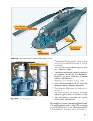
![Configurations of Rotary-Wing Aircraft
Autogyro
An autogyro is an aircraft with a free-spinning horizontal
rotor that turns due to passage of air upward through the
rotor. This air motion is created from forward motion of the
aircraft resulting from either a tractor or pusher configured
engine/propeller design. [Figure 2-24]
Figure 2-26. Dual rotor helicopter.
Types of Rotor Systems
Fully Articulated Rotor
A fully articulated rotor is found on aircraft with more than
two blades and allows movement of each individual blade in
three directions. In this design, each blade can rotate about
Figure 2-24. An autogyro. the pitch axis to change lift; each blade can move back and
forth in plane, lead and lag; and flap up and down through a
Single Rotor Helicopter hinge independent of the other blades. [Figure 2-27]
An aircraft with a single horizontal main rotor that provides
both lift and direction of travel is a single rotor helicopter.
A secondary rotor mounted vertically on the tail counteracts Pitch change axis
the rotational force (torque) of the main rotor to correct yaw
of the fuselage. [Figure 2-25]
Flipping hinge Drag hinge
Figure 2-25. Single rotor helicopter.
Figure 2-27. Articulated rotor head.
Dual Rotor Helicopter
An aircraft with two horizontal rotors that provide both the
lift and directional control is a dual rotor helicopter. The
rotors are counterrotating to balance the aerodynamic torque
and eliminate the need for a separate antitorque system.
[Figure 2-26]
2-18](https://image.slidesharecdn.com/faa-h-8083-31-amt-airframe-vol-1-130226145854-phpapp01/85/Faa-h-8083-31-amt-airframe-vol-1-92-320.jpg)
![Semirigid Rotor In sideward flight, the tip-path plane is tilted sideward in the
The semirigid rotor design is found on aircraft with two rotor direction that flight is desired, thus tilting the total lift-thrust
blades. The blades are connected in a manner such that as vector sideward. In this case, the vertical or lift component
one blade flaps up, the opposite blade flaps down. is still straight up, weight straight down, but the horizontal
or thrust component now acts sideward with drag acting to
Rigid Rotor the opposite side.
The rigid rotor system is a rare design but potentially offers
the best properties of both the fully articulated and semirigid For rearward flight, the tip-path plane is tilted rearward and
rotors. In this design, the blade roots are rigidly attached to the tilts the lift-thrust vector rearward. The thrust is then rearward
rotor hub. The blades do not have hinges to allow lead-lag or and the drag component is forward, opposite that for forward
flapping. Instead, the blades accommodate these motions by flight. The lift component in rearward flight is straight up;
using elastomeric bearings. Elastomeric bearings are molded, weight, straight down.
rubber-like materials that are bonded to the appropriate parts.
Instead of rotating like conventional bearings, they twist and Torque Compensation
flex to allow proper movement of the blades. Newton’s third law of motion states “To every action there
is an equal and opposite reaction.” As the main rotor of a
Forces Acting on the Helicopter helicopter turns in one direction, the fuselage tends to rotate
One of the differences between a helicopter and a fixed-wing in the opposite direction. This tendency for the fuselage to
aircraft is the main source of lift. The fixed-wing aircraft rotate is called torque. Since torque effect on the fuselage is
derives its lift from a fixed airfoil surface while the helicopter a direct result of engine power supplied to the main rotor,
derives lift from a rotating airfoil called the rotor. any change in engine power brings about a corresponding
change in torque effect. The greater the engine power, the
During hovering flight in a no-wind condition, the tip-path greater the torque effect. Since there is no engine power
plane is horizontal, that is, parallel to the ground. Lift and being supplied to the main rotor during autorotation, there
thrust act straight up; weight and drag act straight down. The is no torque reaction during autorotation.
sum of the lift and thrust forces must equal the sum of the
weight and drag forces in order for the helicopter to hover. The force that compensates for torque and provides for
directional control can be produced by various means. The
During vertical flight in a no-wind condition, the lift and defining factor is dictated by the design of the helicopter,
thrust forces both act vertically upward. Weight and drag both some of which do not have a torque issue. Single main
act vertically downward. When lift and thrust equal weight rotor designs typically have an auxiliary rotor located on
and drag, the helicopter hovers; if lift and thrust are less than the end of the tail boom. This auxiliary rotor, generally
weight and drag, the helicopter descends vertically; if lift referred to as a tail rotor, produces thrust in the direction
and thrust are greater than weight and drag, the helicopter opposite the torque reaction developed by the main rotor.
rises vertically. [Figure 2-25] Foot pedals in the flight deck permit the pilot to
increase or decrease tail rotor thrust, as needed, to neutralize
For forward flight, the tip-path plane is tilted forward, thus torque effect.
tilting the total lift-thrust force forward from the vertical. This
resultant lift-thrust force can be resolved into two components: Other methods of compensating for torque and providing
lift acting vertically upward and thrust acting horizontally in directional control include the Fenestron® tail rotor system,
the direction of flight. In addition to lift and thrust, there is an SUD Aviation design that employs a ducted fan enclosed
weight, the downward acting force, and drag, the rearward by a shroud. Another design, called NOTAR®, a McDonald
acting or retarding force of inertia and wind resistance. Douglas design with no tail rotor, employs air directed
through a series of slots in the tail boom, with the balance
In straight-and-level, unaccelerated forward flight, lift equals exiting through a 90° duct located at the rear of the tail boom.
weight and thrust equals drag. (Straight-and-level flight is [Figure 2-28]
flight with a constant heading and at a constant altitude.)
If lift exceeds weight, the helicopter climbs; if lift is less
than weight, the helicopter descends. If thrust exceeds drag,
the helicopter increases speed; if thrust is less than drag, it
decreases speed.
2-19](https://image.slidesharecdn.com/faa-h-8083-31-amt-airframe-vol-1-130226145854-phpapp01/85/Faa-h-8083-31-amt-airframe-vol-1-93-320.jpg)
![Figure 2-28. Aerospatiale Fenestron tail rotor system (left) and the McDonnell Douglas NOTAR® System (right).
Gyroscopic Forces
The spinning main rotor of a helicopter acts like a gyroscope. Examine a two-bladed rotor system to see how gyroscopic
As such, it has the properties of gyroscopic action, one of precession affects the movement of the tip-path plane.
which is precession. Gyroscopic precession is the resultant Moving the cyclic pitch control increases the angle of attack
action or deflection of a spinning object when a force is (AOA) of one rotor blade with the result that a greater lifting
applied to this object. This action occurs approximately 90° force is applied at that point in the plane of rotation. This
in the direction of rotation from the point where the force same control movement simultaneously decreases the AOA
is applied. [Figure 2-29] Through the use of this principle, of the other blade the same amount, thus decreasing the lifting
the tip-path plane of the main rotor may be tilted from the force applied at that point in the plane of rotation. The blade
horizontal. with the increased AOA tends to flap up; the blade with the
Axis New axis Old axis
90
Upward force applied here Reaction occurs here Gyro tips down here Gyro tips up here
Figure 2-29. Gyroscopic precession principle.
2-20](https://image.slidesharecdn.com/faa-h-8083-31-amt-airframe-vol-1-130226145854-phpapp01/85/Faa-h-8083-31-amt-airframe-vol-1-94-320.jpg)
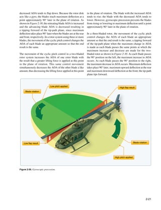
![Helicopter Flight Conditions the engine turns the main rotor system in a counterclockwise
direction, the helicopter fuselage tends to turn clockwise. The
Hovering Flight
amount of torque is directly related to the amount of engine
During hovering flight, a helicopter maintains a constant
power being used to turn the main rotor system. Remember,
position over a selected point, usually a few feet above the
as power changes, torque changes.
ground. For a helicopter to hover, the lift and thrust produced
by the rotor system act straight up and must equal the weight
To counteract this torque-induced turning tendency, an
and drag, which act straight down. [Figure 2-31] While
antitorque rotor or tail rotor is incorporated into most
hovering, the amount of main rotor thrust can be changed
helicopter designs. A pilot can vary the amount of thrust
to maintain the desired hovering altitude. This is done by
produced by the tail rotor in relation to the amount of torque
changing the angle of incidence (by moving the collective)
produced by the engine. As the engine supplies more power
of the rotor blades and hence the AOA of the main rotor
to the main rotor, the tail rotor must produce more thrust to
blades. Changing the AOA changes the drag on the rotor
overcome the increased torque effect. This is done through
blades, and the power delivered by the engine must change
the use of antitorque pedals.
as well to keep the rotor speed constant.
Translating Tendency or Drift
During hovering flight, a single main rotor helicopter tends to
drift or move in the direction of tail rotor thrust. This drifting
Thrust
tendency is called translating tendency. [Figure 2-32]
Lift
otation Tor
de r qu
Bla e
Drift
Weight
Drag
e
qu
Tor tion
Blade rota
Figure 2-31. To maintain a hover at a constant altitude, enough lift Tail rotor
downwash Tail rotor thrust
and thrust must be generated to equal the weight of the helicopter
and the drag produced by the rotor blades.
Figure 2-32. A tail rotor is designed to produce thrust in a direction
The weight that must be supported is the total weight of the opposite torque. The thrust produced by the tail rotor is sufficient
helicopter and its occupants. If the amount of lift is greater to move the helicopter laterally.
than the actual weight, the helicopter accelerates upwards
until the lift force equals the weight gain altitude; if thrust is
less than weight, the helicopter accelerates downward. When To counteract this drift, one or more of the following features
operating near the ground, the effect of the closeness to the may be used. All examples are for a counterclockwise rotating
ground changes this response. main rotor system.
• The main transmission is mounted at a slight angle to
The drag of a hovering helicopter is mainly induced drag the left (when viewed from behind) so that the rotor
incurred while the blades are producing lift. There is, mast has a built-in tilt to oppose the tail rotor thrust.
however, some profile drag on the blades as they rotate
• Flight controls can be rigged so that the rotor disk is
through the air. Throughout the rest of this discussion, the
tilted to the right slightly when the cyclic is centered.
term drag includes both induced and profile drag.
Whichever method is used, the tip-path plane is tilted
slightly to the left in the hover.
An important consequence of producing thrust is torque. As
discussed earlier, Newton’s Third Law states that for every • If the transmission is mounted so the rotor shaft is
action there is an equal and opposite reaction. Therefore, as vertical with respect to the fuselage, the helicopter
2-22](https://image.slidesharecdn.com/faa-h-8083-31-amt-airframe-vol-1-130226145854-phpapp01/85/Faa-h-8083-31-amt-airframe-vol-1-96-320.jpg)
![“hangs” left skid low in the hover. The opposite is Coriolis Effect (Law of Conservation of Angular
true for rotor systems turning clockwise when viewed Momentum)
from above. The Coriolis effect is also referred to as the law of
• In forward flight, the tail rotor continues to push to conservation of angular momentum. It states that the value
the right, and the helicopter makes a small angle with of angular momentum of a rotating body does not change
the wind when the rotors are level and the slip ball is unless an external force is applied. In other words, a rotating
in the middle. This is called inherent sideslip. body continues to rotate with the same rotational velocity
until some external force is applied to change the speed of
Ground Effect rotation. Angular momentum is moment of inertia (mass
When hovering near the ground, a phenomenon known times distance from the center of rotation squared) multiplied
as ground effect takes place. This effect usually occurs at by speed of rotation. Changes in angular velocity, known as
heights between the surface and approximately one rotor angular acceleration and deceleration, take place as the mass
diameter above the surface. The friction of the ground of a rotating body is moved closer to or further away from
causes the downwash from the rotor to move outwards from the axis of rotation. The speed of the rotating mass increases
the helicopter. This changes the relative direction of the or decreases in proportion to the square of the radius. An
downwash from a purely vertical motion to a combination excellent example of this principle is a spinning ice skater.
of vertical and horizontal motion. As the induced airflow The skater begins rotation on one foot, with the other leg
through the rotor disk is reduced by the surface friction, the and both arms extended. The rotation of the skater’s body is
lift vector increases. This allows a lower rotor blade angle for relatively slow. When a skater draws both arms and one leg
the same amount of lift, which reduces induced drag. Ground inward, the moment of inertia (mass times radius squared)
effect also restricts the generation of blade tip vortices due to becomes much smaller and the body is rotating almost faster
the downward and outward airflow making a larger portion than the eye can follow. Because the angular momentum
of the blade produce lift. When the helicopter gains altitude must remain constant (no external force applied), the angular
vertically, with no forward airspeed, induced airflow is no velocity must increase. The rotor blade rotating about the
longer restricted, and the blade tip vortices increase with rotor hub possesses angular momentum. As the rotor begins
the decrease in outward airflow. As a result, drag increases to cone due to G-loading maneuvers, the diameter or the
which means a higher pitch angle, and more power is needed disk shrinks. Due to conservation of angular momentum,
to move the air down through the rotor. the blades continue to travel the same speed even though the
blade tips have a shorter distance to travel due to reduced disk
Ground effect is at its maximum in a no-wind condition over diameter. The action results in an increase in rotor rpm. Most
a firm, smooth surface. Tall grass, rough terrain, and water pilots arrest this increase with an increase in collective pitch.
surfaces alter the airflow pattern, causing an increase in rotor Conversely, as G-loading subsides and the rotor disk flattens
tip vortices. [Figure 2-33] out from the loss of G-load induced coning, the blade tips
Out of Ground Effect (OGE) In Ground Effect (IGE)
No
Large blade tip vortex wind
hover Blade tip vortex
Downwash pattern
equidistant 360°
Figure 2-33. Air circulation patterns change when hovering out of ground effect (OGE) and when hovering in ground effect (IGE).
2-23](https://image.slidesharecdn.com/faa-h-8083-31-amt-airframe-vol-1-130226145854-phpapp01/85/Faa-h-8083-31-amt-airframe-vol-1-97-320.jpg)
![now have a longer distance to travel at the same tip speed.
Resultant
This action results in a reduction of rotor rpm. However, if
this drop in the rotor rpm continues to the point at which it
Lift
attempts to decrease below normal operating rpm, the engine
control system adds more fuel/power to maintain the specified
engine rpm. If the pilot does not reduce collective pitch as
the disk unloads, the combination of engine compensation
Thrust
for the rpm slow down and the additional pitch as G-loading
increases may result in exceeding the torque limitations or
power the engines can produce.
Drag
Helicopter movement
Vertical Flight
Hovering is actually an element of vertical flight. Increasing
the AOA of the rotor blades (pitch) while keeping their
Weight
rotation speed constant generates additional lift and the
helicopter ascends. Decreasing the pitch causes the helicopter
Resultant
to descend. In a no wind condition, when lift and thrust are
less than weight and drag, the helicopter descends vertically.
If lift and thrust are greater than weight and drag, the Figure 2-35. The power required to maintain a straight-and-level
helicopter ascends vertically. [Figure 2-34] flight and a stabilized airspeed.
In straight-and-level (constant heading and at a constant
altitude), unaccelerated forward flight, lift equals weight
and thrust equals drag. If lift exceeds weight, the helicopter
Thrust accelerates vertically until the forces are in balance; if thrust
Vertical ascent
Lift is less than drag, the helicopter slows until the forces are in
balance. As the helicopter moves forward, it begins to lose
altitude because lift is lost as thrust is diverted forward.
However, as the helicopter begins to accelerate, the rotor
system becomes more efficient due to the increased airflow.
The result is excess power over that which is required to
hover. Continued acceleration causes an even larger increase
in airflow through the rotor disk and more excess power. In
Weight order to maintain unaccelerated flight, the pilot must not
Drag make any changes in power or in cyclic movement. Any
such changes would cause the helicopter to climb or descend.
Once straight-and-level flight is obtained, the pilot should
make note of the power (torque setting) required and not
make major adjustments to the flight controls. [Figure 2-36]
Figure 2-34. To ascend vertically, more lift and thrust must be
generated to overcome the forces of weight and drag. Translational Lift
Improved rotor efficiency resulting from directional flight is
Forward Flight
called translational lift. The efficiency of the hovering rotor
In steady forward flight with no change in airspeed or vertical
system is greatly improved with each knot of incoming wind
speed, the four forces of lift, thrust, drag, and weight must
gained by horizontal movement of the aircraft or surface
be in balance. Once the tip-path plane is tilted forward, the
wind. As incoming wind produced by aircraft movement or
total lift-thrust force is also tilted forward. This resultant
surface wind enters the rotor system, turbulence and vortices
lift-thrust force can be resolved into two components—lift
are left behind and the flow of air becomes more horizontal.
acting vertically upward and thrust acting horizontally in the
In addition, the tail rotor becomes more aerodynamically
direction of flight. In addition to lift and thrust, there is weight
efficient during the transition from hover to forward flight.
(the downward acting force) and drag (the force opposing the
Translational thrust occurs when the tail rotor becomes more
motion of an airfoil through the air). [Figure 2-35]
aerodynamically efficient during the transition from hover
2-24](https://image.slidesharecdn.com/faa-h-8083-31-amt-airframe-vol-1-130226145854-phpapp01/85/Faa-h-8083-31-amt-airframe-vol-1-98-320.jpg)
![found on most helicopters which tends to bring the nose
800
of the helicopter to a more level attitude. Figure 2-37 and
Maximum continuous power available
Figure 2-38 show airflow patterns at different speeds and
how airflow affects the efficiency of the tail rotor.
GE
Increasing power for
rO
decreasing airspeed
ove
600
Effective Translational Lift (ETL)
oh
Power required (horsepower)
dt
While transitioning to forward flight at about 16–24 knots,
ire
C A B
the helicopter experiences effective translational lift (ETL).
qu
re
As mentioned earlier in the discussion on translational lift,
er
w
400 Po
Increasing power for the rotor blades become more efficient as forward airspeed
decreasing airspeed
increases. Between 16–24 knots, the rotor system completely
outruns the recirculation of old vortices and begins to work
Maximum in relatively undisturbed air. The flow of air through the
200
continuous rotor system is more horizontal, therefore induced flow
level
(horizontal) and induced drag are reduced. The AOA is subsequently
Minimum power flight increased, which makes the rotor system operate more
for level flight(VY) airspeed (VH)
efficiently. This increased efficiency continues with increased
0
0 40 60 80 100 120 airspeed until the best climb airspeed is reached, and total
drag is at its lowest point.
Indicated airspeed (KIAS)
As speed increases, translational lift becomes more effective,
Figure 2-36. Changing force vectors results in aircraft the nose rises or pitches up, and the aircraft rolls to the right.
movement. The combined effects of dissymmetry of lift, gyroscopic
precession, and transverse flow effect cause this tendency.
to forward flight. As the tail rotor works in progressively
It is important to understand these effects and anticipate
less turbulent air, this improved efficiency produces more
correcting for them. Once the helicopter is transitioning
antitorque thrust, causing the nose of the aircraft to yaw left
through ETL, the pilot needs to apply forward and left
(with a main rotor turning counterclockwise) and forces the
lateral cyclic input to maintain a constant rotor-disk attitude.
pilot to apply right pedal (decreasing the AOA in the tail
[Figure 2-39]
rotor blades) in response. In addition, during this period, the
airflow affects the horizontal components of the stabilizer
b y aft se
cti
sed on of ro
su to r
e c ul e
m ol
1–5 knots
r
y of ai
locit
rd ve
Do wnwa
Figure 2-37. The airflow pattern for 1–5 knots of forward airspeed. Note how the downwind vortex is beginning to dissipate and induced
flow down through the rear of the rotor system is more horizontal.
2-25](https://image.slidesharecdn.com/faa-h-8083-31-amt-airframe-vol-1-130226145854-phpapp01/85/Faa-h-8083-31-amt-airframe-vol-1-99-320.jpg)
![Airflow pattern just prior to effective translational lift
10–15 knots
Figure 2-38. An airflow pattern at a speed of 10–15 knots. At this increased airspeed, the airflow continues to become more horizontal.
The leading edge of the downwash pattern is being overrun and is well back under the nose of the helicopter.
Direction of Flight
More horizontal No recirculation
flow of air of air
Retreating Side Advancing Side
a tion
rot
de
a
Bl
16–24 knots Blade tip Blade tip
Relative wind
Relative wind
speed speed
minus plus
helicopter helicopter
speed speed
Reduced induced flow Tail rotor operates in (200 knots) (400 knots)
increases angle of attack relatively clean air io
n
at
rot
Blade
Figure 2-39. Effective translational lift is easily recognized in actual
flight by a transient induced aerodynamic vibration and increased Forward flight at 100 knots
performance of the helicopter.
Figure 2-40. The blade tip speed of this helicopter is approximately
Dissymmetry of Lift 300 knots. If the helicopter is moving forward at 100 knots, the
Dissymmetry of lift is the differential (unequal) lift between relative windspeed on the advancing side is 400 knots. On the
advancing and retreating halves of the rotor disk caused by the retreating side, it is only 200 knots. This difference in speed causes
different wind flow velocity across each half. This difference a dissymmetry of lift.
in lift would cause the helicopter to be uncontrollable in any
situation other than hovering in a calm wind. There must If this condition was allowed to exist, a helicopter with a
be a means of compensating, correcting, or eliminating this counterclockwise main rotor blade rotation would roll to the
unequal lift to attain symmetry of lift. left because of the difference in lift. In reality, the main rotor
blades flap and feather automatically to equalize lift across
When the helicopter moves through the air, the relative airflow the rotor disk. Articulated rotor systems, usually with three or
through the main rotor disk is different on the advancing side more blades, incorporate a horizontal hinge (flapping hinge)
than on the retreating side. The relative wind encountered to allow the individual rotor blades to move, or flap up and
by the advancing blade is increased by the forward speed down as they rotate. A semirigid rotor system (two blades)
of the helicopter; while the relative windspeed acting on utilizes a teetering hinge, which allows the blades to flap as
the retreating blade is reduced by the helicopter’s forward a unit. When one blade flaps up, the other blade flaps down.
airspeed. Therefore, as a result of the relative windspeed, the
advancing blade side of the rotor disk produces more lift than
the retreating blade side. [Figure 2-40]
2-26](https://image.slidesharecdn.com/faa-h-8083-31-amt-airframe-vol-1-130226145854-phpapp01/85/Faa-h-8083-31-amt-airframe-vol-1-100-320.jpg)
![As the rotor blade reaches the advancing side of the rotor During aerodynamic flapping of the rotor blades as they
disk, it reaches its maximum upward flapping velocity. compensate for dissymmetry of lift, the advancing blade
[Figure 2-41A] When the blade flaps upward, the angle achieves maximum upward flapping displacement over the
between the chord line and the resultant relative wind nose and maximum downward flapping displacement over
decreases. This decreases the AOA, which reduces the the tail. This causes the tip-path plane to tilt to the rear and
amount of lift produced by the blade. At position C, the rotor is referred to as blowback. Figure 2-42 shows how the rotor
blade is at its maximum downward flapping velocity. Due disk is originally oriented with the front down following
to downward flapping, the angle between the chord line and the initial cyclic input. As airspeed is gained and flapping
the resultant relative wind increases. This increases the AOA eliminates dissymmetry of lift, the front of the disk comes
and thus the amount of lift produced by the blade.
The combination of blade flapping and slow relative wind
acting on the retreating blade normally limits the maximum
forward speed of a helicopter. At a high forward speed, the
retreating blade stalls due to high AOA and slow relative
wind speed. This situation is called “retreating blade
stall” and is evidenced by a nose-up pitch, vibration, and
a rolling tendency—usually to the left in helicopters with
counterclockwise blade rotation.
Pilots can avoid retreating blade stall by not exceeding the
never-exceed speed. This speed is designated VNE and is
indicated on a placard and marked on the airspeed indicator Figure 2-42. To compensate for blowback, move the cyclic forward.
by a red line. Blowback is more pronounced with higher airspeeds.
B Angle of attack over nose
Chord
line
Resultant relative wind
n
atio B
rot
de
a
Bl
C Angle of attack at 9 o’clock position A Angle of attack at 3 o’clock position
Chord Chord
line line
C A
Resultant relati
ve wind
wind
Resultant relative Upflap velocity
Downflap velocity
D
D Angle of attack over tail
Chord
line
Relative wind
Angle of attack Resultant relative wind
Figure 2-41. The combined upward flapping (reduced lift) of the advancing blade and downward flapping (increased lift) of the retreating
blade equalizes lift across the main rotor disk counteracting dissymmetry of lift.
2-27](https://image.slidesharecdn.com/faa-h-8083-31-amt-airframe-vol-1-130226145854-phpapp01/85/Faa-h-8083-31-amt-airframe-vol-1-101-320.jpg)
![up, and the back of the disk goes down. This reorientation tilt. At higher forward speeds, the pilot must continue to
of the rotor disk changes the direction in which total rotor move the cyclic forward. This further reduces pitch angle
thrust acts; the helicopter’s forward speed slows, but can be on the advancing blade and further increases pitch angle on
corrected with cyclic input. The pilot uses cyclic feathering the retreating blade. As a result, there is even more tilt to the
to compensate for dissymmetry of lift allowing him or her rotor than at lower speeds.
to control the attitude of the rotor disk.
This horizontal lift component (thrust) generates higher
Cyclic feathering compensates for dissymmetry of lift helicopter airspeed. The higher airspeed induces blade
(changes the AOA) in the following way. At a hover, equal flapping to maintain symmetry of lift. The combination of
lift is produced around the rotor system with equal pitch and flapping and cyclic feathering maintains symmetry of lift and
AOA on all the blades and at all points in the rotor system desired attitude on the rotor system and helicopter.
(disregarding compensation for translating tendency). The
rotor disk is parallel to the horizon. To develop a thrust force, Autorotation
the rotor system must be tilted in the desired direction of Autorotation is the state of flight in which the main rotor
movement. Cyclic feathering changes the angle of incidence system of a helicopter is being turned by the action of air
differentially around the rotor system. Forward cyclic moving up through the rotor rather than engine power driving
movements decrease the angle of incidence at one part on the rotor. In normal, powered flight, air is drawn into the
the rotor system while increasing the angle at another part. main rotor system from above and exhausted downward, but
Maximum downward flapping of the blade over the nose and during autorotation, air moves up into the rotor system from
maximum upward flapping over the tail tilt both rotor disk and below as the helicopter descends. Autorotation is permitted
thrust vector forward. To prevent blowback from occurring, mechanically by a freewheeling unit, which is a special
the pilot must continually move the cyclic forward as the clutch mechanism that allows the main rotor to continue
velocity of the helicopter increases. Figure 2-42 illustrates turning even if the engine is not running. If the engine fails,
the changes in pitch angle as the cyclic is moved forward at the freewheeling unit automatically disengages the engine
increased airspeeds. At a hover, the cyclic is centered and from the main rotor allowing the main rotor to rotate freely.
the pitch angle on the advancing and retreating blades is the It is the means by which a helicopter can be landed safely in
same. At low forward speeds, moving the cyclic forward the event of an engine failure; consequently, all helicopters
reduces pitch angle on the advancing blade and increases must demonstrate this capability in order to be certificated.
pitch angle on the retreating blade. This causes a slight rotor [Figure 2-43]
Normal Powered Flight Autorotation
ht
flig
Direction of flight
of
on
cti
re
Di
Figure 2-43. During an autorotation, the upward flow of relative wind permits the main rotor blades to rotate at their normal speed. In
effect, the blades are “gliding” in their rotational plane.
2-28](https://image.slidesharecdn.com/faa-h-8083-31-amt-airframe-vol-1-130226145854-phpapp01/85/Faa-h-8083-31-amt-airframe-vol-1-102-320.jpg)
![Rotorcraft Controls stationary swash plate by a uniball sleeve. It is connected to
the mast by drive links and is allowed to rotate with the main
Swash Plate Assembly
rotor mast. Both swash plates tilt and slide up and down as
The purpose of the swash plate is to transmit control inputs
one unit. The rotating swash plate is connected to the pitch
from the collective and cyclic controls to the main rotor
horns by the pitch links.
blades. It consists of two main parts: the stationary swash
plate and the rotating swash plate. [Figure 2-44]
There are three major controls in a helicopter that the pilot
must use during flight. They are the collective pitch control,
Pitch link cyclic pitch control, and antitorque pedals or tail rotor control.
In addition to these major controls, the pilot must also use the
Stationary swash plate
throttle control, which is mounted directly to the collective
pitch control in order to fly the helicopter.
Collective Pitch Control
The collective pitch control is located on the left side of the
pilot’s seat and is operated with the left hand. The collective
Rotating swash plate
is used to make changes to the pitch angle of all the main
Control rod rotor blades simultaneously, or collectively, as the name
implies. As the collective pitch control is raised, there is a
simultaneous and equal increase in pitch angle of all main
Figure 2-44. Stationary and rotating swash plate.
rotor blades; as it is lowered, there is a simultaneous and
equal decrease in pitch angle. This is done through a series
The stationary swash plate is mounted around the main rotor
of mechanical linkages, and the amount of movement in the
mast and connected to the cyclic and collective controls
collective lever determines the amount of blade pitch change.
by a series of pushrods. It is restrained from rotating by an
[Figure 2-45] An adjustable friction control helps prevent
antidrive link but is able to tilt in all directions and move
inadvertent collective pitch movement.
vertically. The rotating swash plate is mounted to the
Figure 2-45. Raising the collective pitch control increases the pitch angle by the same amount on all blades.
2-29](https://image.slidesharecdn.com/faa-h-8083-31-amt-airframe-vol-1-130226145854-phpapp01/85/Faa-h-8083-31-amt-airframe-vol-1-103-320.jpg)
![Throttle Control In piston helicopters, the collective pitch is the primary
The function of the throttle is to regulate engine rpm. If the control for manifold pressure, and the throttle is the primary
correlator or governor system does not maintain the desired control for rpm. However, the collective pitch control also
rpm when the collective is raised or lowered, or if those influences rpm, and the throttle also influences manifold
systems are not installed, the throttle must be moved manually pressure; therefore, each is considered to be a secondary
with the twist grip to maintain rpm. The throttle control is control of the other’s function. Both the tachometer (rpm
much like a motorcycle throttle, and works almost the same indicator) and the manifold pressure gauge must be analyzed
way; twisting the throttle to the left increases rpm, twisting to determine which control to use. Figure 2-47 illustrates
the throttle to the right decreases rpm. [Figure 2-46] this relationship.
If manifold
and rpm is Solution
pressure is
Increasing the throttle increases
LOW LOW manifold pressure and rpm
Twist grip throttle
Lowering the collective pitch
HIGH LOW decreases manifold pressure
and increases rpm
Raising the collective pitch
LOW HIGH increases manifold pressure and
decreases rpm
Reducing the throttle decreases
HIGH HIGH manifold pressure and rpm
Figure 2-47. Relationship between manifold pressure, rpm,
Figure 2-46. A twist grip throttle is usually mounted on the end collective, and throttle.
of the collective lever. The throttles on some turbine helicopters
are mounted on the overhead panel or on the floor in the cockpit. Cyclic Pitch Control
The cyclic pitch control is mounted vertically from the
Governor/Correlator cockpit floor, between the pilot’s legs or, in some models,
A governor is a sensing device that senses rotor and engine between the two pilot seats. [Figure 2-48] This primary flight
rpm and makes the necessary adjustments in order to keep control allows the pilot to fly the helicopter in any horizontal
rotor rpm constant. Once the rotor rpm is set in normal direction; fore, aft, and sideways. The total lift force is always
operations, the governor keeps the rpm constant, and there perpendicular to the tip-path place of the main rotor. The
is no need to make any throttle adjustments. Governors are purpose of the cyclic pitch control is to tilt the tip-path plane
common on all turbine helicopters (as it is a function of the in the direction of the desired horizontal direction. The cyclic
fuel control system of the turbine engine), and used on some control changes the direction of this force and controls the
piston-powered helicopters. attitude and airspeed of the helicopter.
A correlator is a mechanical connection between the The rotor disk tilts in the same direction the cyclic pitch
collective lever and the engine throttle. When the collective control is moved. If the cyclic is moved forward, the rotor
lever is raised, power is automatically increased and when disk tilts forward; if the cyclic is moved aft, the disk tilts
lowered, power is decreased. This system maintains rpm aft, and so on. Because the rotor disk acts like a gyro, the
close to the desired value, but still requires adjustment of mechanical linkages for the cyclic control rods are rigged
the throttle for fine tuning. in such a way that they decrease the pitch angle of the rotor
blade approximately 90° before it reaches the direction of
Some helicopters do not have correlators or governors and cyclic displacement, and increase the pitch angle of the
require coordination of all collective and throttle movements. rotor blade approximately 90° after it passes the direction
When the collective is raised, the throttle must be increased; of displacement. An increase in pitch angle increases AOA;
when the collective is lowered, the throttle must be decreased. a decrease in pitch angle decreases AOA. For example, if
As with any aircraft control, large adjustments of either the cyclic is moved forward, the AOA decreases as the rotor
collective pitch or throttle should be avoided. All corrections blade passes the right side of the helicopter and increases on
should be made with smooth pressure. the left side. This results in maximum downward deflection
2-30](https://image.slidesharecdn.com/faa-h-8083-31-amt-airframe-vol-1-130226145854-phpapp01/85/Faa-h-8083-31-amt-airframe-vol-1-104-320.jpg)
![Cyclic pitch control
Cyclic pitch control
Figure 2-49. Antitorque pedals compensate for changes in torque
and control heading in a hover.
Helicopters that are designed with tandem rotors do not have
an antitorque rotor. These helicopters are designed with both
rotor systems rotating in opposite directions to counteract the
torque, rather than using a tail rotor. Directional antitorque
pedals are used for directional control of the aircraft while in
flight, as well as while taxiing with the forward gear off the
Figure 2-48. The cyclic pitch control may be mounted vertically ground. With the right pedal displaced forward, the forward
between the pilot’s knees or on a teetering bar from a single cyclic rotor disk tilts to the right, while the aft rotor disk tilts to
located in the center of the helicopter. The cyclic can pivot in all the left. The opposite occurs when the left pedal is pushed
directions. forward; the forward rotor disk inclines to the left, and the aft
rotor disk tilts to the right. Differing combinations of pedal
of the rotor blade in front of the helicopter and maximum and cyclic application can allow the tandem rotor helicopter
upward deflection behind it, causing the rotor disk to tilt to pivot about the aft or forward vertical axis, as well as
forward. pivoting about the center of mass.
Antitorque Pedals Stabilizer Systems
The antitorque pedals are located on the cabin floor by
Bell Stabilizer Bar System
the pilot’s feet. They control the pitch and, therefore, the
thrust of the tail rotor blades. [Figure 2-49] Newton’s Arthur M. Young discovered that stability could be increased
Third Law applies to the helicopter fuselage and how it significantly with the addition of a stabilizer bar perpendicular
rotates in the opposite direction of the main rotor blades to the two blades. The stabilizer bar has weighted ends, which
unless counteracted and controlled. To make flight possible cause it to stay relatively stable in the plane of rotation. The
and to compensate for this torque, most helicopter designs stabilizer bar is linked with the swash plate in a manner that
incorporate an antitorque rotor or tail rotor. The antitorque reduces the pitch rate. The two blades can flap as a unit and,
pedals allow the pilot to control the pitch angle of the tail therefore, do not require lag-lead hinges (the whole rotor
rotor blades which in forward flight puts the helicopter in slows down and accelerates per turn). Two-bladed systems
longitudinal trim and while at a hover, enables the pilot to require a single teetering hinge and two coning hinges to
turn the helicopter 360°. The antitorque pedals are connected permit modest coning of the rotor disk as thrust is increased.
to the pitch change mechanism on the tail rotor gearbox and The configuration is known under multiple names, including
allow the pitch angle on the tail rotor blades to be increased Hiller panels, Hiller system, Bell-Hiller system, and flybar
or decreased. system.
2-31](https://image.slidesharecdn.com/faa-h-8083-31-amt-airframe-vol-1-130226145854-phpapp01/85/Faa-h-8083-31-amt-airframe-vol-1-105-320.jpg)
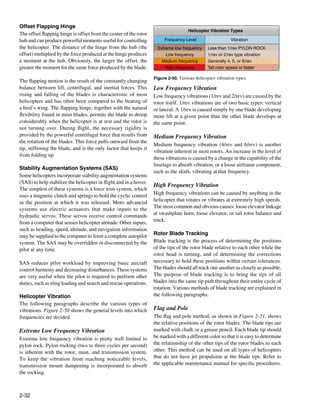
![Curtain
80°
to
Curtain 0°
Leading edge
7
Blade BLADE
Pole
Position of chalk mark (approximately 2 inches long)
Pole
Handle Line parallel to longitudinal axis of helicopter
Curtain
1/2" max spread (typical)
Approximate position of chalk marks
Pole
Figure 2-51. Flag and pole blade tracking.
Electronic Blade Tracker
The most common electronic blade tracker consists of
a Balancer/Phazor, Strobex Tracker, and Vibrex Tester. Meter
[Figures 2-52 through 2-54] The Strobex blade tracker
A Channel B
permits blade tracking from inside or outside the helicopter A B
TRACK
while on the ground or inside the helicopter in flight. The COMMON
system uses a highly concentrated light beam flashing in MAGNETIC
PICKUP
FUNCTION
Band-pass filter
BALANCER
sequence with the rotation of the main rotor blades so that a MODEL 177M-6A
RPM TONE
fixed target at the blade tips appears to be stopped. Each blade X10
X100
X1 PUSH FOR
is identified by an elongated retroreflective number taped or SCALE 2
attached to the underside of the blade in a uniform location. RPM RANGE Phase meter
When viewed at an angle from inside the helicopter, the taped DOUBLE TEST
10
11
12
1
2
numbers will appear normal. Tracking can be accomplished PHAZOR 9
8 4
3
with tracking tip cap reflectors and a strobe light. The tip
7 5
6
caps are temporarily attached to the tip of each blade. The
high-intensity strobe light flashes in time with the rotating
blades. The strobe light operates from the aircraft electrical
power supply. By observing the reflected tip cap image, it is Figure 2-52. Balancer/Phazor.
possible to view the track of the rotating blades. Tracking is
accomplished in a sequence of four separate steps: ground
tracking, hover verification, forward flight tracking, and auto
rotation rpm adjustment.
2-33](https://image.slidesharecdn.com/faa-h-8083-31-amt-airframe-vol-1-130226145854-phpapp01/85/Faa-h-8083-31-amt-airframe-vol-1-107-320.jpg)
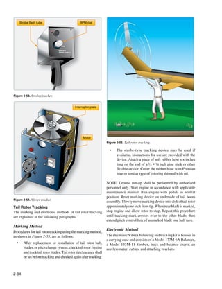
![The Vibrex balancing kit is used to measure and indicate the Reciprocating Engine
level of vibration induced by the main rotor and tail rotor of The reciprocating engine consists of a series of pistons
a helicopter. The Vibrex analyzes the vibration induced by connected to a rotating crankshaft. As the pistons move up
out-of-track or out-of-balance rotors, and then by plotting and down, the crankshaft rotates. The reciprocating engine
vibration amplitude and clock angle on a chart the amount gets its name from the back-and-forth movement of its
and location of rotor track or weight change is determined. In internal parts. The four-stroke engine is the most common
addition, the Vibrex is used in troubleshooting by measuring type, and refers to the four different cycles the engine
the vibration levels and frequencies or rpm of unknown undergoes to produce power. [Figure 2-56]
disturbances.
Intake valve Exhaust valve
Rotor Blade Preservation and Storage
Accomplish the following requirements for rotor blade
preservation and storage:
• Condemn, demilitarize, and dispose of locally any
blade which has incurred nonrepairable damage.
Spark plug
• Tape all holes in the blade, such as tree damage, or Piston
foreign object damage (FOD) to protect the interior
of the blade from moisture and corrosion.
• Thoroughly remove foreign matter from the entire
exterior surface of blade with mild soap and water.
• Protect blade outboard eroded surfaces with a light
coating of corrosion preventive or primer coating. Crankshaft Connecting rod
• Protect blade main bolt hole bushing, drag brace
1. Intake 2. Compression
retention bolt hole bushing, and any exposed bare
metal (i.e., grip and drag pads) with a light coating of
corrosion preventive.
• Secure blade to shock-mounted support and secure
container lid.
• Place copy of manufacturer’s blade records, containing
information required by Title 14 of the Code of Federal
Regulations (14 CFR) section 91.417(a)(2)(ii), and
any other blade records in a waterproof bag and insert
into container record tube.
• Obliterate old markings from the container that
pertained to the original shipment or to the original
3. Power 4. Exhaust
item it contained. Stencil the blade National Stock
Number (NSN), model, and serial number, as
applicable, on the outside of the container. Figure 2-56. The arrows indicate the direction of motion of the
crankshaft and piston during the four-stroke cycle.
Helicopter Power Systems
Powerplant When the piston moves away from the cylinder head on
The two most common types of engines used in helicopters are the intake stroke, the intake valve opens and a mixture of
the reciprocating engine and the turbine engine. Reciprocating fuel and air is drawn into the combustion chamber. As the
engines, also called piston engines, are generally used cylinder moves back toward the cylinder head, the intake
in smaller helicopters. Most training helicopters use valve closes, and the fuel/air mixture is compressed. When
reciprocating engines because they are relatively simple and compression is nearly complete, the spark plugs fire and the
inexpensive to operate. Turbine engines are more powerful compressed mixture is ignited to begin the power stroke.
and are used in a wide variety of helicopters. They produce a The rapidly expanding gases from the controlled burning of
tremendous amount of power for their size but are generally the fuel/air mixture drive the piston away from the cylinder
more expensive to operate. head, thus providing power to rotate the crankshaft. The
2-35](https://image.slidesharecdn.com/faa-h-8083-31-amt-airframe-vol-1-130226145854-phpapp01/85/Faa-h-8083-31-amt-airframe-vol-1-109-320.jpg)
![piston then moves back toward the cylinder head on the flight conditions. The main components of the transmission
exhaust stroke where the burned gases are expelled through system are the main rotor transmission, tail rotor drive
the opened exhaust valve. Even when the engine is operated system, clutch, and freewheeling unit. The freewheeling unit,
at a fairly low speed, the four-stroke cycle takes place several or autorotative clutch, allows the main rotor transmission to
hundred times each minute. In a four-cylinder engine, each drive the tail rotor drive shaft during autorotation. Helicopter
cylinder operates on a different stroke. Continuous rotation transmissions are normally lubricated and cooled with their
of a crankshaft is maintained by the precise timing of the own oil supply. A sight gauge is provided to check the
power strokes in each cylinder. oil level. Some transmissions have chip detectors located
in the sump. These detectors are wired to warning lights
Turbine Engine located on the pilot’s instrument panel that illuminate in the
The gas turbine engine mounted on most helicopters is event of an internal problem. The chip detectors on modern
made up of a compressor, combustion chamber, turbine, helicopters have a “burn off” capability and attempt to correct
and accessory gearbox assembly. The compressor draws the situation without pilot action. If the problem cannot be
filtered air into the plenum chamber and compresses it. The corrected on its own, the pilot must refer to the emergency
compressed air is directed to the combustion section through procedures for that particular helicopter.
discharge tubes where atomized fuel is injected into it. The
fuel/air mixture is ignited and allowed to expand. This Main Rotor Transmission
combustion gas is then forced through a series of turbine The primary purpose of the main rotor transmission is
wheels causing them to turn. These turbine wheels provide to reduce engine output rpm to optimum rotor rpm. This
power to both the engine compressor and the accessory reduction is different for the various helicopters. As an
gearbox. Power is provided to the main rotor and tail rotor example, suppose the engine rpm of a specific helicopter
systems through the freewheeling unit which is attached is 2,700. A rotor speed of 450 rpm would require a 6:1
to the accessory gearbox power output gear shaft. The reduction. A 9:1 reduction would mean the rotor would turn
combustion gas is finally expelled through an exhaust outlet. at 300 rpm. Most helicopters use a dual-needle tachometer
[Figure 2-57] or a vertical scale instrument to show both engine and rotor
rpm or a percentage of engine and rotor rpm. The rotor rpm
Transmission System indicator normally is used only during clutch engagement to
The transmission system transfers power from the engine to monitor rotor acceleration, and in autorotation to maintain
the main rotor, tail rotor, and other accessories during normal rpm within prescribed limits. [Figure 2-58]
Gearbox
Compression Section Turbine Section Combustion Section
Section
Exhaust air outlet N2 Rotor Stator N1 Rotor
Compressor rotor
Igniter plug
Air inlet
Fuel nozzle
Gear
Inlet air
Compressor discharge air Output Shaft
Combustion liner
Combustion gases
Exhaust gases
Figure 2-57. Many helicopters use a turboshaft engine to drive the main transmission and rotor systems. The main difference between
a turboshaft and a turbojet engine is that most of the energy produced by the expanding gases is used to drive a turbine rather than
producing thrust through the expulsion of exhaust gases.
2-36](https://image.slidesharecdn.com/faa-h-8083-31-amt-airframe-vol-1-130226145854-phpapp01/85/Faa-h-8083-31-amt-airframe-vol-1-110-320.jpg)
![Clutch
In a conventional airplane, the engine and propeller are
20 E R permanently connected. However, in a helicopter there is
15 25
3
10
2 4
30 110
100
110
100
a different relationship between the engine and the rotor.
Because of the greater weight of a rotor in relation to the
90 90
1 5 80 80
R
RPM 70 70
5 35
R
power of the engine, as compared to the weight of a propeller
X
X100 60 60
50 50
ROTOR
0 40
ENGINE % RPM and the power in an airplane, the rotor must be disconnected
from the engine when the starter is engaged. A clutch allows
% RPM the engine to be started and then gradually pick up the load
120
110 of the rotor.
105
50
60 70 On free turbine engines, no clutch is required, as the gas
ROTOR 80 100
40 EE
E
PEEVER
TURBINEA 90
R
producer turbine is essentially disconnected from the power
95
30
R 100
turbine. When the engine is started, there is little resistance
20
PERCENT
C
RPM
P
110
90
80
from the power turbine. This enables the gas producer turbine
10
to accelerate to normal idle speed without the load of the
T
0 120 70
60
40
0
transmission and rotor system dragging it down. As the gas
NR NP
pressure increases through the power turbine, the rotor blades
begin to turn, slowly at first and then gradually accelerate to
normal operating rpm.
Figure 2-58. There are various types of dual-needle tachometers;
however, when the needles are superimposed, or married, the ratio On reciprocating helicopters, the two main types of clutches
of the engine rpm is the same as the gear reduction ratio. are the centrifugal clutch and the belt drive clutch.
In helicopters with horizontally mounted engines, another Centrifugal Clutch
purpose of the main rotor transmission is to change the axis of The centrifugal clutch is made up of an inner assembly and
rotation from the horizontal axis of the engine to the vertical an outer drum. The inner assembly, which is connected to
axis of the rotor shaft. [Figure 2-59] the engine driveshaft, consists of shoes lined with material
similar to automotive brake linings. At low engine speeds,
springs hold the shoes in, so there is no contact with the outer
drum, which is attached to the transmission input shaft. As
Main rotor engine speed increases, centrifugal force causes the clutch
shoes to move outward and begin sliding against the outer
drum. The transmission input shaft begins to rotate, causing
Antitorque rotor
the rotor to turn, slowly at first, but increasing as the friction
increases between the clutch shoes and transmission drum.
As rotor speed increases, the rotor tachometer needle shows
an increase by moving toward the engine tachometer needle.
When the two needles are superimposed, the engine and the
rotor are synchronized, indicating the clutch is fully engaged
and there is no further slippage of the clutch shoes.
Main transmission
Belt Drive Clutch
to engine
Some helicopters utilize a belt drive to transmit power from
Gearbox the engine to the transmission. A belt drive consists of a
lower pulley attached to the engine, an upper pulley attached
Figure 2-59. The main rotor transmission and gearbox reduce engine to the transmission input shaft, a belt or a series of V-belts,
output rpm to optimum rotor rpm and change the axis of rotation and some means of applying tension to the belts. The belts
of the engine output shaft to the vertical axis for the rotor shaft.
2-37](https://image.slidesharecdn.com/faa-h-8083-31-amt-airframe-vol-1-130226145854-phpapp01/85/Faa-h-8083-31-amt-airframe-vol-1-111-320.jpg)
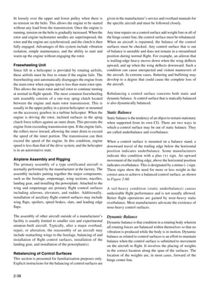
![Trim tabs on the surface should be secured in the neutral
position when the control surface is mounted on the stand.
Chord line
The stand must be level and be located in an area free of air
currents. The control surface must be permitted to rotate
freely about the hinge points without binding. Balance
Tail-down underbalance
condition is determined by the behavior of the trailing edge
Plus ( + ) condition
when the surface is suspended from its hinge points. Any
excessive friction would result in a false reaction as to the
overbalance or underbalance of the surface.
Chord line
When installing the control surface in the stand or jig, a
neutral position should be established with the chord line of
Nose-down overbalance the surface in a horizontal position. Use a bubble protractor
Minus ( − ) condition to determine the neutral position before continuing balancing
procedures. [Figure 2-62]
Chord line
Hinge center line Bubble protractor
Level-horizontal position
Balance condition
Support stand
Figure 2-60. Control surface static balance. Chord line
Rebalancing Procedures
Figure 2-62. Establishing a neutral position of the control
Repairs to a control surface or its tabs generally increase the
surface.
weight aft of the hinge center line, requiring static rebalancing
of the control surface system, as well as the tabs. Control
surfaces to be rebalanced should be removed from the aircraft
and supported, from their own points, on a suitable stand,
jig, or fixture. [Figure 2-61]
Inboard hinge fitting
Outboard hinge fitting
Figure 2-61. Locally fabricated balancing fixture.
2-39](https://image.slidesharecdn.com/faa-h-8083-31-amt-airframe-vol-1-130226145854-phpapp01/85/Faa-h-8083-31-amt-airframe-vol-1-113-320.jpg)
![Sometimes a visual check is all that is needed to determine
whether the surface is balanced or unbalanced. Any trim tabs Bubble protractor Mounting bracket
or other assemblies that are to remain on the surface during
Trim tab Rudder Hinge center line
balancing procedures should be in place. If any assemblies
or parts must be removed before balancing, they should be
removed.
Rebalancing Methods
Several methods of balancing (rebalancing) control surfaces
are in use by the various manufacturers of aircraft. The most
common are the calculation method, scale method, and the
balance beam method. Adjustable support
The calculation method of balancing a control surface has one Support stand
advantage over the other methods in that it can be performed
Weight scale
without removing the surface from the aircraft. In using the
calculation method, the weight of the material from the repair
area and the weight of the materials used to accomplish the
repair must be known. Subtract the weight removed from
the weight added to get the resulting net gain in the amount
added to the surface. The distance from the hinge center line
to the center of the repair area is then measured in inches. This
distance must be determined to the nearest one-hundredth of
an inch. [Figure 2-63]
Figure 2-64. Balancing setup.
Center of repair area The balance beam method is used by the Cessna and Piper
Measurement in inches Aircraft companies. This method requires that a specialized
tool be locally fabricated. The manufacturer’s maintenance
manual provides specific instructions and dimensions to
fabricate the tool.
Hinge center line Chord line Once the control surface is placed on level supports, the
weight required to balance the surface is established by
moving the sliding weight on the beam. The maintenance
Figure 2-63. Calculation method measurement.
manual indicates where the balance point should be. If the
surface is found to be out of tolerance, the manual explains
The next step is to multiply the distance times the net weight
where to place weight to bring it into tolerance.
of the repair. This results in an inch-pounds (in-lb) answer.
If the in-lb result of the calculations is within specified
Aircraft manufacturers use different materials to balance
tolerances, the control surface is considered balanced. If
control surfaces, the most common being lead or steel.
it is not within specified limits, consult the manufacturer’s
Larger aircraft manufacturers may use depleted uranium
service manuals for the needed weights, material to use for
because it has a heavier mass than lead. This allows the
weights, design for manufacture, and installation locations
counterweights to be made smaller and still retain the same
for addition of the weights.
weight. Specific safety precautions must be observed when
handling counterweights of depleted uranium because it is
The scale method of balancing a control surface requires the
radioactive. The manufacturer’s maintenance manual and
use of a scale that is graduated in hundredths of a pound.
service instructions must be followed and all precautions
A support stand and balancing jigs for the surface are also
observed when handling the weights.
required. Figure 2-64 illustrates a control surface mounted
for rebalancing purposes. Use of the scale method requires
the removal of the control surface from the aircraft.
2-40](https://image.slidesharecdn.com/faa-h-8083-31-amt-airframe-vol-1-130226145854-phpapp01/85/Faa-h-8083-31-amt-airframe-vol-1-114-320.jpg)
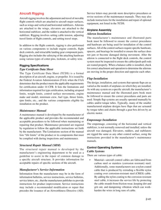
![• Cable construction—the basic component of a cable
is a wire. The diameter of the wire determines the
total diameter of the cable. A number of wires are
preformed into a helical or spiral shape and then
formed into a strand. These preformed strands are laid
around a straight center strand to form a cable.
• Cable designations—based on the number of strands
and wires in each strand. The 7 × 19 cable is made up 3 1 2
of seven strands of 19 wires each. Six of these strands
are laid around the center strand. This cable is very
flexible and is used in primary control systems and
in other locations where operation over pulleys is
frequent. The 7 × 7 cable consists of seven strands of
seven wires each. Six of these strands are laid around
Figure 2-66. Typical Nicopress® thimble-eye splice.
the center strand. This cable is of medium flexibility
and is used for trim tab controls, engine controls, and
indicator controls. [Figure 2-65]
1/8 — 3/8 diameter 7 x 19 AN663 Double shank ball end terminal
7 strands, 19 wires to each strand Diameter
1/16 — 3/32 diameter 7 x 7 AN664 Single shake ball end terminal
7 strands, 7 wires to each strand Diameter
Figure 2-65. Cable construction and cross-section.
AN665 Rod end terminal
Types of control cable termination include:
• Woven splice—a hand-woven 5-tuck splice used on
aircraft cable. The process is very time consuming and
produces only about 75 percent of the original cable AN666 Threaded cable terminal
strength. The splice is rarely used except on some
antique aircraft where the effort is made to keep all
parts in their original configuration.
• Nicopress® process—a patented process using copper
sleeves and may be used up to the full rated strength of
AN667 Fork end cable terminal
the cable when the cable is looped around a thimble.
[Figure 2-66] This process may also be used in place
of the 5-tuck splice on cables up to and including 3⁄8-
inch diameter. Whenever this process is used for cable
splicing, it is imperative that the tools, instructions,
and data supplied by Nicopress® be followed exactly AN667 Eye end cable terminal
to ensure the desired cable function and strength
is attained. The use of sleeves that are fabricated Figure 2-67. Swage-type terminal fittings.
of material other than copper requires engineering
approval for the specific application by the FAA. When swaging tools are used, it is imperative that all the
• Swage-type terminals—manufactured in accordance manufacturer’s instructions, including ‘go’ and ‘no-go’
with Army-Navy (AN) and Military Standards (MS), dimensions, be followed exactly to avoid defective and
are suitable for use in civil aircraft up to, and including, inferior swaging. Compliance with all of the instructions
maximum cable loads. [Figure 2-67] should result in the terminal developing the full-rated strength
2-42](https://image.slidesharecdn.com/faa-h-8083-31-amt-airframe-vol-1-130226145854-phpapp01/85/Faa-h-8083-31-amt-airframe-vol-1-116-320.jpg)
![of the cable. The following basic procedures are used when
swaging terminals onto cable ends: 1
• Cut the cable to length, allowing for growth during
swaging. Apply a preservative compound to the cable
end before insertion into the terminal barrel. Measure
the internal length of the terminal end/barrel of the
fitting to determine the proper length of the cable to Bend cable, then push into swaging position
be inserted. Transfer that measurement to the end of
the cable and mark it with a piece of masking tape 2
wrapped around the cable. This provides a positive
mark to ensure the cable did not slip during the
swaging process.
NOTE: Never solder the cable ends to prevent fraying
since the solder greatly increases the tendency of the
cable to pull out of the terminal. Figure 2-68. Insertion of cable into terminal.
• Insert the cable into the terminal approximately one
inch and bend it toward the terminal. Then, push the
cable end all the way into the terminal. The bending
action puts a slight kink in the cable end and provides
enough friction to hold the terminal in place until the
swaging operation is performed. [Figure 2-68]
• Accomplish the swaging operation in accordance with
the instructions furnished by the manufacturer of the
swaging equipment.
• Inspect the terminal after swaging to determine that it
is free of die marks and splits and is not out of round.
Check the cable for slippage at the masking tape and Figure 2-69. Gauging terminal shank dimension after swaging.
for cut and broken wire strands.
fittings for proper strength before installation. This
• Using a go/no-go gauge supplied by the swaging is conducted by slowly applying a test load equal to
tool manufacturer or a micrometer and swaging 60 percent of the rated breaking strength of the cable
chart, check the terminal shank diameter for proper listed in Figure 2-71.
dimension. [Figures 2-69 and 2-70]
• Test the cable by proof-loading locally fabricated
splices and newly installed swage terminal cable
Before Swaging After Swaging
Cable size Wire Outside Bore Bore Swaging Minimum breaking
Shank diameter *
(inches) strands diameter diameter length length strength (pounds)
1/16 7x7 0.160 0.078 1.042 0.969 480 0.138
3/32 7x7 0.218 0.109 1.261 1.188 920 0.190
1/8 7 x 19 0.250 0.141 1.511 1.438 2,000 0.219
5/32 7 x 19 0.297 0.172 1.761 1.688 2,800 0.250
3/16 7 x 19 0.359 0.203 2.011 1.938 4,200 0.313
7/32 7 x 19 0.427 0.234 2.261 2.188 5,600 0.375
1/4 7 x 19 0.494 0.265 2.511 2.438 7,000 0.438
9/32 7 x 19 0.563 0.297 2.761 2.688 8,000 0.500
5/16 7 x 19 0.635 0.328 3.011 2.938 9,800 0.563
3/8 7 x 19 0.703 0.390 3.510 3.438 14,400 0.625
*Use gauges in kit for checking diameters.
Figure 2-70. Straight shank terminal dimensions.
2-43](https://image.slidesharecdn.com/faa-h-8083-31-amt-airframe-vol-1-130226145854-phpapp01/85/Faa-h-8083-31-amt-airframe-vol-1-117-320.jpg)
![Minimum Breaking Strength (Pounds)
Allowable
Tolerance
Nominal diameter increase of
Construction on diameter MIL-W-83420 MIL-W-83420 MIL-C-18375
of wire rope cable diameter
(plus only) COMP A COMP B (CRES) (CRES)
at cut end
INCHES INCHES INCHES POUNDS POUNDS POUNDS
1/32 3x7 0.006 0.006 110 110
3/64 7x7 0.008 0.008 270 270
1/16 7x7 0.010 0.009 480 480 360
1/16 7 x 19 0.010 0.009 480 480
3/32 7x7 0.012 0.010 920 920 700
3/32 7 x 19 0.012 0.010 1,000 920
1/8 7 x 19 0.014 0.011 2,000 1,760 1,300
5/32 7 x 19 0.016 0.017 2,800 2,400 2,000
3/16 7 x 19 0.018 0.019 4,200 3,700 2,900
7/32 7 x 19 0.018 0.020 5,000 5,000 3,800
1/4 7 x 19 0.018 0.021 6,400 6,400 4,900
9/32 7 x 19 0.020 0.023 7,800 7,800 6,100
5/16 7 x 19 0.022 0.024 9,800 9,000 7,600
11/32 7 x 19 0.024 0.025 12,500
3/8 7 x 19 0.026 0.027 14,400 12,000 11,000
7/16 6 x 19 IWRC 0.030 0.030 17,600 16,300 14,900
1/2 6 x 19 IWRC 0.033 0.033 22,800 22,800 19,300
9/16 6 x 19 IWRC 0.036 0.036 28,500 28,500 24,300
5/8 6 x 19 IWRC 0.039 0.039 35,000 35,000 30,100
3/4 6 x 19 IWRC 0.045 0.045 49,600 49,600 42,900
7/8 6 x 19 IWRC 0.048 0.048 66,500 66,500 58,000
1 6 x 19 IWRC 0.050 0.050 85,400 85,400 75,200
1 - 1/8 6 x 19 IWRC 0.054 0.054 106,400 106,400
1 - 1/4 6 x 19 IWRC 0.057 0.057 129,400 129,400
1 - 3/8 6 x 19 IWRC 0.060 0.060 153,600 153,600
1 - 1/2 6 x 19 IWRC 0.062 0.062 180,500 180,500
Figure 2-71. Flexible cable construction.
This load should be held for at least 3 minutes. Any testing or within 1 foot of a swaged-on fitting. Close inspection in
of this type can be dangerous. Suitable guards should be these critical fatigue areas can be performed by rubbing a rag
placed over the cable during the test to prevent injury to along the cable. If there are any broken strands, the rag snags
personnel in the event of cable failure. If a proper test fixture on the cable. A more detailed inspection can be performed
is not available, the load test should be contracted out and in areas that may be corroded or indicate a fatigue failure by
performed by a properly equipped facility. loosing or removing the cable and bending it. This technique
reveals internal broken strands not readily apparent from the
Cable Inspection outside. [Figure 2-72]
Aircraft cable systems are subject to a variety of environmental
conditions and deterioration. Wire or strand breakage is easy Cable System Installation
to recognize visually. Other kinds of deterioration, such as Cable Guides
wear, corrosion, and distortion, are not easily seen. Special Pulleys are used to guide cables and also to change the
attention should be given to areas where cables pass through direction of cable movement. Pulley bearings are sealed
battery compartments, lavatories, and wheel wells. These are and need no lubrication other than the lubrication done at
prime areas for corrosion. Special attention should be given to the factory. Brackets fastened to the structure of the aircraft
critical fatigue areas. Those areas are defined as anywhere the support the pulleys. Cables passing over pulleys are kept
cable runs over, under, or around a pulley, sleeve, or through in place by guards. The guards are close fitting to prevent
a fairlead; or any section where the cable is flexed, rubbed,
2-44](https://image.slidesharecdn.com/faa-h-8083-31-amt-airframe-vol-1-130226145854-phpapp01/85/Faa-h-8083-31-amt-airframe-vol-1-118-320.jpg)
![in place. If a retaining ring comes off, it may slide along the
cable and cause jamming of a pulley. [Figure 2-74]
Travel Adjustment
Control surfaces should move a certain distance in either
direction from the neutral position. These movements must
be synchronized with the movement of the flight deck
controls. The flight control system must be adjusted (rigged)
to obtain these requirements. The tools for measuring surface
travel primarily include protractors, rigging fixtures, contour
templates, and rulers. These tools are used when rigging
flight control systems to assure that the desired travel has
been obtained. Generally speaking, the rigging consists of
the following:
1. Positioning the flight control system in neutral and
Figure 2-72. Cable inspection technique.
temporarily locking it there with rig pins or blocks;
jamming or to prevent the cables from slipping off when 2. Adjusting system cable tension and maintaining
they slacken due to temperature variations. Pulleys should rudder, elevator, and ailerons in the neutral position;
be examined to ensure proper lubrication; smooth rotation and
and freedom from abnormal cable wear patterns which can
provide an indication of other problems in the cable system. 3. Adjusting the control stops to the aircraft manufacturer’s
[Figure 2-73] specifications.
Cable Tension
For the aircraft to operate as it was designed, the cable tension
for the flight controls must be correct. To determine the
Excessive cable tension Pully wear from misalignment amount of tension on a cable, a tensiometer is used. When
properly maintained, a tensiometer is 98 percent accurate.
Cable tension is determined by measuring the amount of force
needed to make an offset in the cable between two hardened
steel blocks called anvils. A riser or plunger is pressed against
Pully too large for cable Cable misalignment the cable to form the offset. Several manufacturers make
a variety of tensiometers, each type designed for different
kinds of cable, cable sizes, and cable tensions. [Figure 2-75]
Rigging Fixtures
Frozen bearing Normal condition
Rigging fixtures and templates are special tools (gauges)
designed by the manufacturer to measure control surface
Figure 2-73. Pulley wear patterns.
travel. Markings on the fixture or template indicate desired
control surface travel.
Fairleads may be made from a nonmetallic material, such as
phenolic, or a metallic material, such as soft aluminum. The Tension Regulators
fairlead completely encircles the cable where it passes through Cable tension regulators are used in some flight control
holes in bulkheads or other metal parts. Fairleads are used to systems because there is considerable difference in
guide cables in a straight line through or between structural temperature expansion of the aluminum aircraft structure
members of the aircraft. Fairleads should never deflect the and the steel control cables. Some large aircraft incorporate
alignment of a cable more than 3° from a straight line. tension regulators in the control cable systems to maintain
a given cable tension automatically. The unit consists of a
Pressure seals are installed where cables (or rods) move compression spring and a locking mechanism that allows the
through pressure bulkheads. The seal grips tightly enough spring to make correction in the system only when the cable
to prevent excess air pressure loss but not enough to hinder system is in neutral.
movement of the cable. Pressure seals should be inspected
at regular intervals to determine that the retaining rings are
2-45](https://image.slidesharecdn.com/faa-h-8083-31-amt-airframe-vol-1-130226145854-phpapp01/85/Faa-h-8083-31-amt-airframe-vol-1-119-320.jpg)
![Fairlead
Rubstrip
Split fairlead
Solid fairlead
Retaining rings
Control cable
Guard pin
Bulkhead groove
d
rize
ressu
Unp
Bracket
zed
suri
Pres
Air seal Bulkhead
Pulley
Figure 2-74. Cable guides.
When installing a turnbuckle in a control system, it is
Pointer Lock Riser Anvil necessary to screw both of the terminals an equal number of
turns into the barrel. It is also essential that all turnbuckle
Anvil terminals be screwed into the barrel until not more than three
threads are exposed on either side of the turnbuckle barrel.
After a turnbuckle is properly adjusted, it must be safetied.
There are a number of methods to safety a turnbuckle and/
or other types of swaged cable ends that are satisfactory. A
120 double-wrap safety wire method is preferred.
0
100
20 Some turnbuckles are manufactured and designed to
80
40 60 accommodate special locking devices. A typical unit is shown
in Figure 2-77.
Trigger
Cable Connectors
In addition to turnbuckles, cable connectors are used in some
Figure 2-75. Tensiometer. systems. These connectors enable a cable length to be quickly
connected or disconnected from a system. Figure 2-78
Turnbuckles
illustrates one type of cable connector in use.
A turnbuckle assembly is a mechanical screw device
consisting of two threaded terminals and a threaded barrel. Spring-Back
[Figure 2-76] Turnbuckles are fitted in the cable assembly
With a control cable properly rigged, the flight control should
for the purpose of making minor adjustments in cable length
hit its stops at both extremes prior to the flight deck control.
and for adjusting cable tension. One of the terminals has
The spring-back is the small extra push that is needed for the
right-hand threads, and the other has left-hand threads. The
flight deck control to hit its mechanical stop.
barrel has matching right- and left-hand internal threads. The
end of the barrel with the left-hand threads can usually be
identified by a groove or knurl around that end of the barrel.
2-46](https://image.slidesharecdn.com/faa-h-8083-31-amt-airframe-vol-1-130226145854-phpapp01/85/Faa-h-8083-31-amt-airframe-vol-1-120-320.jpg)
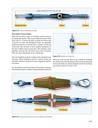
![Checknut Threaded rod end Tube
Adjustable antifriction rod end Rivets Adjustable rod end clevis
Figure 2-79. Push rod.
Quadrant
Anchored end
Flange
Peening
Flange ends
Torque tube
Figure 2-80. Attached rod end.
Another alternative is to place a washer, having a larger
diameter than the hole in the flange, under the retaining nut
on the end of the attaching pin or bolt. This retains the rod Horn
on the bolt in the event of a bearing failure.
Push-pull rod
Torque Tubes
Where an angular or twisting motion is needed in a control
system, a torque tube is installed. Figure 2-81 shows how a
torque tube is used to transmit motion in opposite directions. Figure 2-81. Torque tube.
[Figure 2-81]
also provide information regarding control surface movement
Cable Drums and weight and balance limits.
Cable drums are used primarily in trim tab systems.
The purpose of this section is to explain the methods of
As the trim tab control wheel is moved clockwise or
checking the relative alignment and adjustment of an
counterclockwise, the cable drum winds or unwinds to actuate
aircraft’s main structural components. It is not intended
the trim tab cables. [Figure 2-82]
to imply that the procedures are exactly as they may be
in a particular aircraft. When rigging an aircraft, always
Rigging Checks
follow the procedures and methods specified by the aircraft
All aircraft assembly and rigging must be performed in
manufacturer.
accordance with the requirements prescribed by the specific
aircraft and/or aircraft component manufacturer. Correctly
Structural Alignment
following the procedures provides for proper operation
of the components in regard to their mechanical and The position or angle of the main structural components is
aerodynamic function and ensures the structural integrity related to a longitudinal datum line parallel to the aircraft
of the aircraft. Rigging procedures are detailed in the center line and a lateral datum line parallel to a line joining
applicable manufacturer’s maintenance or service manuals the wing tips. Before checking the position or angle of the
and applicable structural repair manuals. Additionally, main components, the aircraft must be jacked and leveled.
aircraft specification or type certificate data sheets (TCDS)
2-48](https://image.slidesharecdn.com/faa-h-8083-31-amt-airframe-vol-1-130226145854-phpapp01/85/Faa-h-8083-31-amt-airframe-vol-1-122-320.jpg)
![Bearing Shaft Drum
Control wheel
Figure 2-82. Trim tab cable drum.
Small aircraft usually have fixed pegs or blocks attached to With a few exceptions, the dihedral and incidence angles
the fuselage parallel to or coincident with the datum lines. of conventional modern aircraft cannot be adjusted. Some
A spirit level and a straight edge are rested across the pegs manufacturers permit adjusting the wing angle of incidence
or blocks to check the level of the aircraft. This method of to correct for a wing-heavy condition. The dihedral and
checking aircraft level also applies to many of the larger types incidence angles should be checked after hard landings or
of aircraft. However, the grid method is sometimes used on after experiencing abnormal flight loads to ensure that the
large aircraft. The grid plate is a permanent fixture installed components are not distorted and that the angles are within
on the aircraft floor or supporting structure. [Figure 2-83] the specified limits.
When the aircraft is to be leveled, a plumb bob is suspended There are several methods for checking structural alignment
from a predetermined position in the ceiling of the aircraft and rigging angles. Special rigging boards that incorporate,
over the grid plate. The adjustments to the jacks necessary to or on which can be placed, a special instrument (spirit level
level the aircraft are indicated on the grid scale. The aircraft or inclinometer) for determining the angle are used on some
is level when the plumb bob is suspended over the center aircraft. On a number of aircraft, the alignment is checked
point of the grid. using a transit and plumb bobs or a theodolite and sighting
rods. The particular equipment to use is usually specified in
Certain precautions must be observed in all instances when the manufacturer’s maintenance manual.
jacking an aircraft. Normally, rigging and alignment checks
should be performed in an enclosed hangar. If this cannot When checking alignment, a suitable sequence should be
be accomplished, the aircraft should be positioned with the developed and followed to be certain that the checks are
nose into the wind. made at all the positions specified. The alignment checks
specified usually include:
The weight and loading of the aircraft should be exactly as • Wing dihedral angle
described in the manufacturer’s manual. In all cases, the
aircraft should not be jacked until it is determined that the • Wing incidence angle
maximum jacking weight (if applicable) specified by the • Verticality of the fin
manufacturer is not exceeded.
2-49](https://image.slidesharecdn.com/faa-h-8083-31-amt-airframe-vol-1-130226145854-phpapp01/85/Faa-h-8083-31-amt-airframe-vol-1-123-320.jpg)
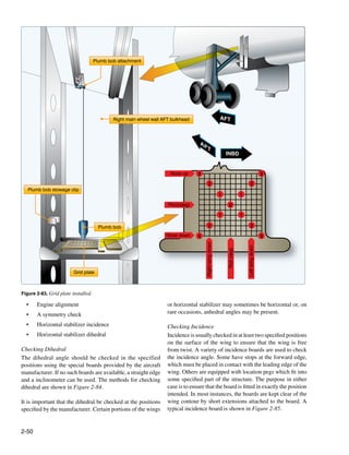
![Special dihedral board with Straight edge and
spirit level incorporated adjustable level
Figure 2-84. Checking dihedral.
Bubble level
Straight edge and adjustable level
Stop Incidence board
Chord line
Figure 2-85. A typical incidence board.
When used, the board is placed at the specified locations on Checking Fin Verticality
the surface being checked. If the incidence angle is correct, After the rigging of the horizontal stabilizer has been checked,
a inclinometer on top of the board reads zero, or within a the verticality of the vertical stabilizer relative to the lateral
specified tolerance of zero. Modifications to the areas where datum can be checked. The measurements are taken from a
incidence boards are located can affect the reading. For given point on either side of the top of the fin to a given point
example, if leading edge deicer boots have been installed, on the left and right horizontal stabilizers. [Figure 2-86] The
the position of a board having a leading edge stop is affected. measurements should be similar within prescribed limits.
When it is necessary to check the alignment of the rudder
String or tape measure
lateral datum
Figure 2-86. Checking fin verticality.
2-51](https://image.slidesharecdn.com/faa-h-8083-31-amt-airframe-vol-1-130226145854-phpapp01/85/Faa-h-8083-31-amt-airframe-vol-1-125-320.jpg)
![hinges, remove the rudder and pass a plumb bob line through suspending a plumb bob from the checkpoints and marking
the rudder hinge attachment holes. The line should pass the floor immediately under the point of each plumb bob.
centrally through all the holes. It should be noted that some The measurements are then taken between the centers of
aircraft have the leading edge of the vertical fin offset to the each marking.
longitudinal center line to counteract engine torque.
Cable Tension
Checking Engine Alignment When it has been determined that the aircraft is symmetrical
Engines are usually mounted with the thrust line parallel to and structural alignment is within specifications, the cable
the horizontal longitudinal plane of symmetry. However, this tension and control surface travel can be checked.
is not always true when the engines are mounted on the wings.
Checking to ensure that the position of the engines, including To determine the amount of tension on a cable, a tensiometer
any degree of offset is correct, depends largely on the type of is used. When properly maintained, a tensiometer is 98
mounting. Generally, the check entails a measurement from percent accurate. Cable tension is determined by measuring
the center line of the mounting to the longitudinal center the amount of force needed to make an offset in the cable
line of the fuselage at the point specified in the applicable between two hardened steel blocks called anvils. A riser or
manual. [Figure 2-87] plunger is pressed against the cable to form the offset. Several
manufacturers make a variety of tensiometers, each type
Symmetry Check designed for different kinds of cable, cable sizes, and cable
The principle of a typical symmetry check is illustrated in tensions. One type of tensiometer is illustrated in Figure 2-88.
Figure 2-87. The precise figures, tolerances, and checkpoints
for a particular aircraft are found in the applicable service or Following the manufacturer’s instructions, lower the trigger.
maintenance manual. Then, place the cable to be tested under the two anvils and
close the trigger (move it up). Movement of the trigger pushes
On small aircraft, the measurements between points are usually up the riser, which pushes the cable at right angles to the two
taken using a steel tape. When measuring long distances, it is clamping points under the anvils. The force that is required
suggested that a spring scale be used with the tape to obtain to do this is indicated by the dial pointer. As the sample chart
equal tension. A five-pound pull is usually sufficient. beneath the illustration shows, different numbered risers are
used with different size cables. Each riser has an identifying
On large aircraft, the positions at which the dimensions are number and is easily inserted into the tensiometer.
to be taken are usually chalked on the floor. This is done by
Figure 2-87. Typical measurements used to check aircraft symmetry.
2-52](https://image.slidesharecdn.com/faa-h-8083-31-amt-airframe-vol-1-130226145854-phpapp01/85/Faa-h-8083-31-amt-airframe-vol-1-126-320.jpg)
![in flight control, landing gear, and other cable-operated
Pointer lock Riser Anvil systems. [Figure 2-89]
Anvil
To use the chart, determine the size of the cable that is to
be adjusted and the ambient air temperature. For example,
assume that the cable size is 1/8" diameter, which is a 7-19
cable and the ambient air temperature is 85 °F. Follow the
85 °F line upward to where it intersects the curve for 1/8"
120 cable. Extend a horizontal line from the point of intersection
0
to the right edge of the chart. The value at this point indicates
100
20 the tension (rigging load in pounds) to establish on the cable.
80 The tension for this example is 70 pounds.
40 60
Trigger Control Surface Travel
Example
In order for a control system to function properly, it must
No. 1 Riser No. 2 No. 3 be correctly adjusted. Correctly rigged control surfaces
move through a prescribed arc (surface-throw) and are
Diameter Tension
5/32 3/16 7/32 1/4 synchronized with the movement of the flight deck controls.
1/16 3/32 1/8 (lb)
Rigging any control system requires that the aircraft
12 16 21 30 12 20
manufacturer’s instructions be followed as outlined in their
19 23 29 40 17 26
maintenance manual.
25 30 36 50 22 32
31 36 43 60 26 37
Therefore, the explanations in this chapter are limited to the
36 42 50 70 30 42
41 48 57 80 34 47
three general steps listed below:
46 54 63 90 38 52 1. Lock the flight deck control, bellcranks, and the
51 60 69 100 42 56 control surfaces in the neutral position.
110 46 60
2. Adjust the cable tension, maintaining the rudder,
120 50 64
elevators, or ailerons in the neutral position.
Figure 2-88. Cable tensiometer and sample conversion chart. 3. Adjust the control stops to limit the control surface
travel to the dimensions given for the aircraft being
Included with each tensiometer is a conversion chart, which is rigged.
used to convert the dial reading to pounds. The dial reading is
converted to pounds of tension as follows. Using a No. 2 riser The range of movement of the controls and control
to measure the tension of a 5/32" diameter cable, a reading of surfaces should be checked in both directions from neutral.
30 is obtained. The actual tension (see chart) of the cable is There are various tools used for measuring surface travel,
70 lbs. Referring to the chart, also notice that a No. 1 riser is including protractors, rigging fixtures, contour templates,
used with 1/16", 3/32", and 1/8" cable. Since the tensiometer and rulers. These tools are used when rigging flight control
is not designed for use in measuring 7/32" or 1/4" cable, no systems to ensure that the aircraft is properly rigged and
values are shown in the No. 3 riser column of the chart. the manufacturer’s specifications have been complied with.
When actually taking a reading of cable tension in an aircraft, Rigging fixtures and contour templates are special tools
it may be difficult to see the dial. Therefore, a pointer lock (gauges) designed by the manufacturer to measure control
is built in on the tensiometer. Push it in to lock the pointer, surface travel. Markings on the fixture or template indicate
then remove the tensiometer from the cable and observe the desired control surface travel. In many instances, the aircraft
reading. After observing the reading, pull the lock out and manufacturer gives the travel of a particular control surface
the pointer returns to zero. in degrees and inches. If the travel in inches is provided, a
ruler can be used to measure surface travel in inches.
Another variable that must be taken into account when
adjusting cable tension is the ambient temperature of cable Protractors are tools for measuring angles in degrees. Various
and the aircraft. To compensate for temperature variations, types of protractors are used to determine the travel of flight
cable rigging charts are used when establishing cable tensions control surfaces. One protractor that can be used to measure
2-53](https://image.slidesharecdn.com/faa-h-8083-31-amt-airframe-vol-1-130226145854-phpapp01/85/Faa-h-8083-31-amt-airframe-vol-1-127-320.jpg)
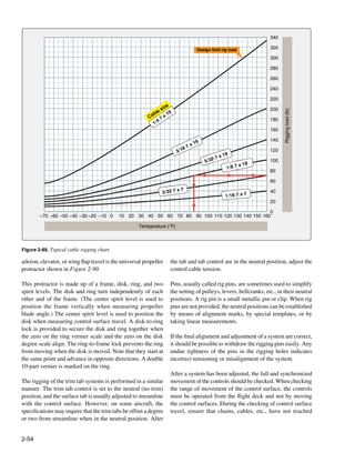
![that they are not extended beyond the specified limits when
Ring vernier scale Center spirit level the tab is in its extreme positions.
Disk adjuster Ring Disk degree scale
After determining that the control system functions properly
Disk Ring adjuster and is correctly rigged, it should be thoroughly inspected to
determine that the system is correctly assembled and operates
0
10 10
freely over the specified range of movement.
30 2 0 1
0
0
10 Checking and Safetying the System
20
Whenever rigging is performed on any aircraft, it is good
0
30
0
practice to have a second set of eyes inspect the control
system to make certain that all turnbuckles, rod ends, and
attaching nuts and bolts are correctly safetied.
As a general rule, all fasteners on an aircraft are safetied in
some manner. Safetying is defined as securing by various
means any nut, bolt, turnbuckle, etc., on the aircraft so that
vibration does not cause it to loosen during operation.
Corner spirit level Ring-to-frame lock Most aircraft manufacturers have a Standard Practices section
on frame folded in
in their maintenance manuals. These are the methods that
Disk-to-ring lock on ring engages only should be used when working on a particular system of a
when zeros on scales are aligned. specific aircraft. However, most standard aircraft hardware
has a standard method of being safetied. The following
information provides some of the most common methods
Figure 2-90. Universal propeller protractor.
used in aircraft safetying.
the limit of their travel when the controls are against their
respective stops. The most commonly used safety wire method is the double-
twist, utilizing stainless steel or Monel wire in the .032 to
Adjustable and nonadjustable stops (whichever the case .040-inch diameter range. This method is used on studs, cable
requires) are used to limit the throw-range or travel movement turnbuckles, flight controls, and engine accessory attaching
of the ailerons, elevator, and rudder. Usually there are two bolts. A single-wire method is used on smaller screws, bolts,
sets of stops for each of the three main control surfaces. One and/or nuts when they are located in a closely spaced or
set is located at the control surface, either in the snubber closed geometrical pattern. The single-wire method is also
cylinders or as structural stops; the other, at the flight deck used on electrical components and in places that are difficult
control. Either of these may serve as the actual limit stop. to reach. [Figure 2-91]
However, those situated at the control surface usually perform
this function. The other stops do not normally contact each Safety-of-flight emergency equipment, such as portable fire
other, but are adjusted to a definite clearance when the extinguishers, oxygen regulators, emergency valves, firewall
control surface is at the full extent of its travel. These work shut-offs, and seals on first-aid kits, are safetied using a single
as override stops to prevent stretching of cables and damage copper wire (.020-inch diameter) or aluminum wire (.031-
to the control system during violent maneuvers. When rigging inch diameter). The wire on this emergency equipment is
control systems, refer to the applicable maintenance manual installed only to indicate the component is sealed or has not
for the sequence of steps for adjusting these stops to limit the been actuated. It must be possible to break the wire seal by
control surface travel. hand, without the use of any tools.
Where dual controls are installed, they must be synchronized The use of safety wire pliers, or wire twisters, makes the
and function satisfactorily when operated from both positions. job of safetying much easier on the mechanic’s hands and
produces a better finished product. [Figure 2-92]
Trim tabs and other tabs should be checked in a manner
similar to the main control surfaces. The tab position The wire should have six to eight twists per inch of wire
indicator must be checked to see that it functions correctly. and be pulled taut while being installed. Where practicable,
If jackscrews are used to actuate the trim tab, check to see install the safety wire around the head of the fastener and
2-55](https://image.slidesharecdn.com/faa-h-8083-31-amt-airframe-vol-1-130226145854-phpapp01/85/Faa-h-8083-31-amt-airframe-vol-1-129-320.jpg)
![Outer sleeve
To
loc
kj
aw
s
Small screw in closely spaced closed
geometrical pattern • Single-twist method
Pu
ll k
no
bt
ot
wis
tw
ire
Plier handles will spin
when knob is pulled
Single-fastener application • Double-twist method
Figure 2-92. Use of safety-wire pliers or wire twisters.
Cotter pins are used to secure such items as bolts, screws,
pins, and shafts. They are used at any location where a turning
Screwheads • Double-twist method or actuating movement takes place. The diameter of the cotter
pin selected for any application should be the largest size that
will fit consistent with the diameter of the cotter pin hole and/
or the slots in the castellated nut. Cotter pins, like safety wire,
should never be re-used on aircraft. [Figure 2-94]
Self-locking nuts are used in applications where they are
not removed often. There are two types of self-locking nuts
External snapring • Single-wire method currently in use. One is all metal and the other has an insert,
usually of fiber or nylon.
It is extremely important that the manufacturer’s Illustrated
Parts Book (IPB) be consulted for the correct type and
grade of lock nut for various locations on the aircraft.
Castle nuts
The finish or plating color of the nut identifies the type of
application and environment in which it can be used. For
example, a cadmium-plated nut is gold in color and provides
exceptionally good protection against corrosion, but should
not be used in applications where the temperature may
Bolt heads exceed 450 °F.
Figure 2-91. Double-wrap and single safety wire methods for nuts, Repeated removal and installation causes the self-locking nut
bolts, and snap rings. to lose its locking feature. They should be replaced when they
are no longer capable of maintaining the minimum prevailing
twist it in such a manner that the loop of the wire is pulled torque. [Figure 2-95]
close to the contour of the unit being safety wired, and in
the direction that would have the tendency to tighten the
fastener. [Figure 2-93]
2-56](https://image.slidesharecdn.com/faa-h-8083-31-amt-airframe-vol-1-130226145854-phpapp01/85/Faa-h-8083-31-amt-airframe-vol-1-130-320.jpg)
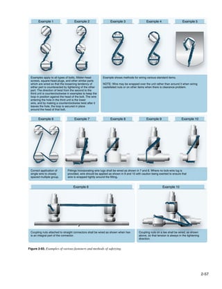
![spring steel and are to be used only once and replaced with
new ones when removed.
Biplane Assembly and Rigging
Biplanes were some of the very first aircraft designs. The
first powered heavier-than-air aircraft, the Wright brothers’
Wright Flyer, successfully flown on December 17, 1903,
was a biplane.
The first biplanes were designed with very thin wing
sections and, consequently, the wing structure needed to
be strengthened by external bracing wires. The biplane
configuration allowed the two wings to be braced against
one another, increasing the structural strength. When the
assembly and rigging of a biplane is accomplished in
Figure 2-94. Securing hardware with cotter pins. accordance with the approved instructions, a stable airworthy
aircraft is the result.
Fine Thread Series
Thread Size Minimum Prevailing Torque Whether assembling an early model vintage aircraft that
may have been disassembled for repair and restoration, or
7/16 - 20 8 inch-pounds
constructing and assembling a new aircraft, the following are
1/2 - 20 10 inch-pounds
some basic alignment procedures to follow.
9/16 - 18 13 inch-pounds
5/8 - 18 18 inch-pounds
To start, the fuselage must be level, fore and aft and laterally.
3/4 - 16 27 inch-pounds
The aircraft usually has specific leveling points designated
7/8 - 14 40 inch-pounds
by the manufacturer or indicated on the plans. The fuselage
1 - 14 55 inch-pounds
should be blocked up off the landing gear so it is stable. A
1-1/8 - 12 73 inch-pounds
center line should be drawn on the floor the length of the
1-1/4 - 12 94 inch-pounds
fuselage and another line perpendicular to it at the firewall,
Coarse Thread Series for use as an additional alignment reference.
Thread Size Minimum Prevailing Torque With the horizontal and vertical tail surfaces installed, the
7/16 - 14 8 inch-pounds incident angle for the horizontal stabilizer should be set.
1/2 - 13 10 inch-pounds The tail brace wires should be connected and tightened until
9/16 - 12 14 inch-pounds the slack is removed. Alignment measurements should be
5/8 - 11 20 inch-pounds checked as shown in Figure 2-96.
3/4 - 10 27 inch-pounds
7/8 - 9 40 inch-pounds Install the elevator and rudder and clamp them in a neutral
1-8 51 inch-pounds position. Verify the neutral position of the control stick and
1-1/8 - 8 68 inch-pounds rudder pedals in the flight deck and secure them in order to
1-1/4 - 8 68 inch-pounds simplify the connecting and final tensioning of the control
cables.
Figure 2-95. Minimum prevailing torque values for reused self-
locking unts. If the biplane has a center section for the upper wing, it
Lock washers may be used with bolts and machine screws must be aligned as accurately as possible, because even the
whenever a self-locking nut or castellated nut is not smallest error is compounded at the wing tip. Applicable
applicable. They may be of the split washer spring type, or cables and turnbuckles should be connected and the tension
a multi-serrated internal or external star washer. set as specified. [Figure 2-97] The stagger measurement can
be checked as shown in Figure 2-98.
Pal nuts may be a second nut tightened against the first and
used to force the primary nut thread against the bolt or screw The lower wing sections should be individually attached to
thread. They may also be of the type that are made of stamped the fuselage and blocked up for support while the landing
2-58](https://image.slidesharecdn.com/faa-h-8083-31-amt-airframe-vol-1-130226145854-phpapp01/85/Faa-h-8083-31-amt-airframe-vol-1-132-320.jpg)
![Note Distance “Y” Fuselage centerline
same both sides
• Make cross-
90° Straight edge -
measurements with a 50'
clamp to firewall
steel tape.
Select easy-to-identify • Ideally, distances on
points from which to both sides should match.
cross-measure. (A1-A2 / B1-B2, etc.)
90°
90°
Firewall centerline
CENTER SECTION
Top view
C1 B1 D1 D2 B2 C2 Both tie rods “Z” Level
same length 90°
Reference point
Z Z
Distance
Top view “X” same X X Ruler
both sides
Vertical tail post (reference)
9 8 7 6 5 4 3 2 1 1 2 3 4 5 6 7 8 9
Plumb bob
A1 A2
90°
0
90°
Rear view Front view
Figure 2-96. Checking aircraft symmetry. Figure 2-97. Center section alignment.
wires are connected and adjusted to obtain the dihedral called opposite wire. Flying and landing wires are typically set at
for in the specifications or plans. [Figure 2-99] about 600 pounds and tail brace wires at about 300 pounds
of tension.
Next, connect the outer “N” struts to the left and right sections
of the lower wing. Now, the upper wing can be attached and When convinced the aircraft is properly rigged, move away
the flying wires installed. The slave struts can be installed from it and take a good look at the finished product. Are the
and the ailerons connected using the same alignment and wings symmetrical? Does the dihedral look even? Is the tail
adjustment procedures used for the elevator and rudder. The section square with the fuselage? Are the wing attaching
incidence angle can be checked, as shown in Figure 2-100. hardware, flying wires, and control cables safetied? And
the final task, before the first flight, is to complete the
Once this point is reached, it is a matter of measuring, maintenance record entries.
checking angles, and adjusting the various components to
obtain the overall aircraft symmetry and desired alignment, As with any aircraft maintenance or repair, the instructions
as shown in Figure 2-96. and specifications from the manufacturer, or the procedures
and recommendations found in the construction plans, should
Also, remember that care should be used when tightening the be the primary method to perform the assembly and rigging
wing wires because extra stress can be inadvertently induced of the aircraft.
into the wings. Always loosen one wire before tightening the
2-59](https://image.slidesharecdn.com/faa-h-8083-31-amt-airframe-vol-1-130226145854-phpapp01/85/Faa-h-8083-31-amt-airframe-vol-1-133-320.jpg)
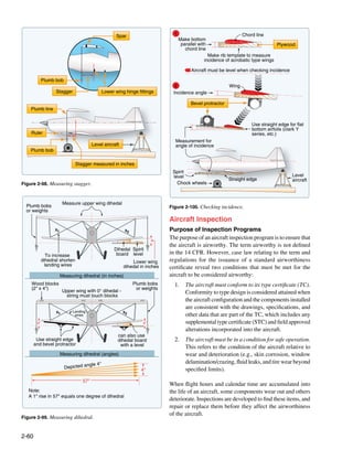
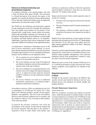
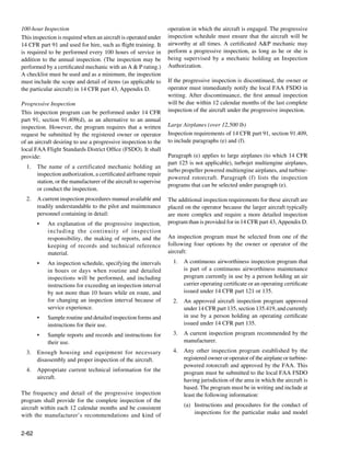
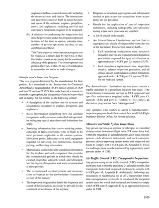
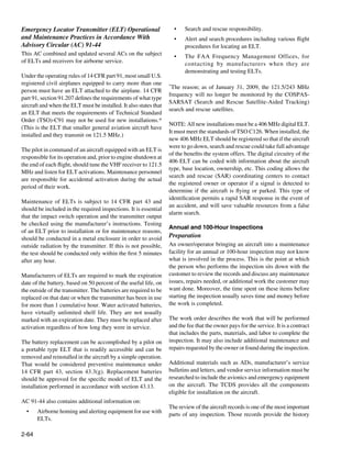

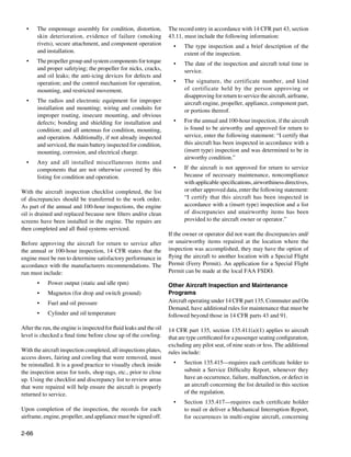
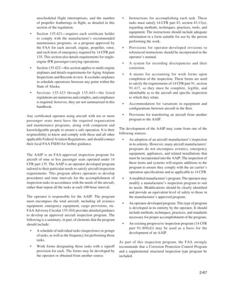
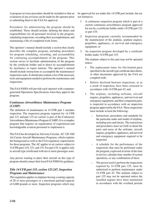
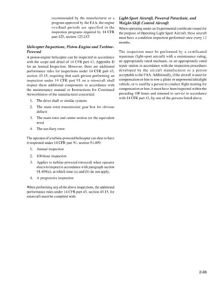

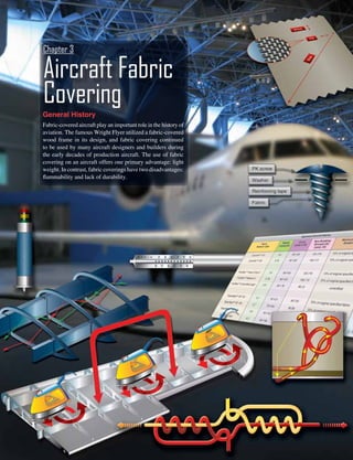
![Finely woven organic fabrics, such as Irish linen and cotton,
were the original fabrics used for covering airframes, but
their tendency to sag left the aircraft structure exposed to the
elements. To counter this problem, builders began coating the
fabrics with oils and varnishes. In 1916, a mixture of cellulose
dissolved in nitric acid, called nitrate dope, came into use as
an aircraft fabric coating. Nitrate dope protected the fabric,
adhered to it well, and tautened it over the airframe. It also
gave the fabric a smooth, durable finish when dried. The
major drawback to nitrate dope was its extreme flammability.
To address the flammability issue, aircraft designers tried
a preparation of cellulose dissolved in butyric acid called
butyrate dope. This mixture protected the fabric from dirt
and moisture, but it did not adhere as well to the fabric as
nitrate dope. Eventually, a system combining the two dope
coatings was developed. First, the fabric was coated with
nitrate dope for its adhesion and protective qualities. Then,
subsequent coats of butyrate dope were added. Since the
butyrate dope coatings reduced the overall flammability of
the fabric covering, this system became the standard fabric
treatment system.
Figure 3-1. Examples of aircraft produced using fabric skin.
The second problem, lack of durability, stems from the
eventual deterioration of fabric from exposure to the elements produced with fabric coverings. [Figure 3-1] The nitrate/
that results in a limited service life. Although the mixture of butyrate dope process works well, but does not mitigate
nitrate dope and butyrate dope kept out dirt and water, solving the short lifespan of organic fabrics. It was not until the
some of the degradation issue, it did not address deterioration introduction of polyester fabric as an aircraft covering in
caused by ultraviolet (UV) radiation from the sun. Ultraviolet the 1950s that the problem of the limited lifespan of fabric
radiation passed through the dope and degraded not only the covering was solved. The transition to polyester fabric had
fabric, but also the aircraft structure underneath. Attempts to some problems because the nitrate and butyrate dope coating
paint the coated fabric proved unsuccessful, because paint process is not as suitable for polyester as it is for organic
does not adhere well to nitrate dope. Eventually, aluminum fabrics. Upon initial application of the dopes to polyester,
solids were added to the butyrate coatings. This mixture good adhesion and protection occurred; as the dopes dried,
reflected the sun’s rays, prevented harmful UV rays from they would eventually separate from the fabric. In other
penetrating the dope, and protected the fabric, as well as the words, the fabric outlasted the coating.
aircraft structure.
Eventually, dope additives were developed that minimized
Regardless of treatments, organic fabrics have a limited the separation problem. For example, plasticizers keep the
lifespan; cotton or linen covering on an actively flown aircraft dried dope flexible and nontautening dope formulas eliminate
lasts only about 5–10 years. Furthermore, aircraft cotton has separation of the coatings from the fabric. Properly protected
not been available for over 25 years. As the aviation industry and coated, polyester lasts indefinitely and is stronger
developed more powerful engines and more aerodynamic than cotton or linen. Today, polyester fabric coverings are
aircraft structures, aluminum became the material of the standard and use of cotton and linen on United States
choice. Its use in engines, aircraft frames, and coverings certificated aircraft has ceased. In fact, the long staple cotton
revolutionized aviation. As a covering, aluminum protected from which grade-A cotton aircraft fabric is made is no longer
the aircraft structure from the elements, was durable, and produced in this country.
was not flammable.
Re-covering existing fabric aircraft is an accepted maintenance
Although aluminum and composite aircraft dominate modern procedure. Not all aircraft covering systems include the use
aviation, advances in fabric coverings continue to be made of dope coating processes. Modern aircraft covering systems
because gliders, home-built, and light sport aircraft, as well that include the use of nondope fabric treatments show no
as some standard and utility certificated aircraft, are still signs of deterioration even after decades of service. In this
3-2](https://image.slidesharecdn.com/faa-h-8083-31-amt-airframe-vol-1-130226145854-phpapp01/85/Faa-h-8083-31-amt-airframe-vol-1-146-320.jpg)
![chapter, various fabrics and treatment systems are discussed, • Count—the number of threads per inch in warp or
as well as basic covering techniques. filling.
• Ply—the number of yarns making up a thread.
Fabric Terms
• Bias—a cut, fold, or seam made diagonally to the warp
To facilitate the discussion of fabric coverings for aircraft,
or fill threads.
the following definitions are presented. Figure 3-2 illustrates
some of these items. • Pinked edge—an edge which has been cut by machine
or special pinking shears in a continuous series of Vs
to prevent raveling.
Pinked edge
• Selvage edge—the edge of cloth, tape, or webbing
woven to prevent raveling.
• Greige—condition of polyester fabric upon completion
of the production process before being heat shrunk.
Warp
• Cross coat—brushing or spraying where the second
coat is applied 90° to the direction the first coat was
applied. The two coats together make a single cross
Fill
coat. [Figure 3-3]
Legal Aspects of Fabric Covering
Selvage edge
When a fabric-covered aircraft is certificated, the aircraft
as manufacturer uses materials and techniques to cover the
Bi
aircraft that are approved under the type certificate issued
for that aircraft. The same materials and techniques must be
Selvage edge
used by maintenance personnel when replacing the aircraft
fabric. Descriptions of these materials and techniques are
in the manufacturer’s service manual. For example, aircraft
originally manufactured with cotton fabric can only be
re-covered with cotton fabric unless the Federal Aviation
Administration (FAA) approves an exception. Approved
exceptions for alternate fabric-covering materials and
procedures are common. Since polyester fabric coverings
Figure 3-2. Aircraft fabric nomenclature.
deliver performance advantages, such as lighter weight,
longer life, additional strength, and lower cost, many older
• Warp—the direction along the length of fabric. aircraft originally manufactured with cotton fabric have
received approved alteration authority and have been re-
• Fill or weave—the direction across the width of the
covered with polyester fabric.
fabric.
Second application
(applied when first
First application coat is tacky)
Figure 3-3. A single cross coat is made up of two coats of paint applied 90° to each other.
3-3](https://image.slidesharecdn.com/faa-h-8083-31-amt-airframe-vol-1-130226145854-phpapp01/85/Faa-h-8083-31-amt-airframe-vol-1-147-320.jpg)
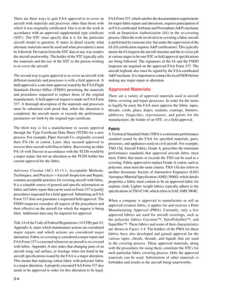
![Approved Aircraft Fabrics
Fabric Weight Count New Breaking Minimum Deteriorated TSO
Name or Type (oz/sq yd) (warp x fill) Strength (lb) Breaking Strength
(warp, fill)
Ceconite™ 101 3.5 69 x 63 125,116 70% of original specified fabric C-15d
Ceconite™ 102 3.16 60 x 60 106,113 70% of original specified fabric C-15d
Polyfiber™ Heavy Duty-3 3.5 69 x 63 125,116 70% of original specified fabric C-15d
Polyfiber™ Medium-3 3.16 60 x 60 106,113 70% of original specified fabric C-15d
Polyfiber™ Uncertified Light 1.87 90 x 76 66,72 uncertified
Superflight™ SF 101 3.7 70 x 51 80,130 70% of original specified fabric C-15d
Superflight™ SF 102 2.7 72 x 64 90,90 70% of original specified fabric C-15d
Superflight™ SF 104 1.8 94 x 91 75,55 uncertified
Grade A Cotton 4.5 80 x 84 80,80 56 lb/in (70% of New) C-15d
Figure 3-4. Approved fabrics for covering aircraft.
Other Fabric Covering Materials
The following is an introduction to the supplemental materials
used to complete a fabric covering job per manufacturer’s
instruction or a STC.
Anti-Chafe Tape
Anti-chafe tape is used on sharp protrusions, rib caps, metal
seams, and other areas to provide a smoother surface to keep
the fabric from being torn. It is usually self-adhesive cloth
tape and is applied after the aircraft is cleaned, inspected,
and primed, but before the fabric is installed.
Reinforcing Tape Figure 3-5. Inter-rib bracing holds the ribs in place during the
Reinforcing tape is most commonly used on rib caps after covering process.
the fabric covering is installed to protect and strengthen the
It is used over seams, ribs, patches, and edges. Surface tape
area for attaching the fabric to the ribs.
can have straight or pinked edges and comes in various
widths. For curved surfaces, bias cut tape is available, which
Rib Bracing allows the tape to be shaped around a radius.
Rib bracing tape is used on wing ribs before the fabric is
installed. It is applied spanwise and alternately wrapped Rib Lacing Cord
around a top rib cap and then a bottom rib cap progressing
Rib lacing cord is used to lace the fabric to the wing ribs.
from rib to rib until all are braced. [Figure 3-5] Lacing
It must be strong and applied as directed to safely transfer
the ribs in this manner holds them in the proper place and
in-flight loads from the fabric to the ribs. Rib lacing cord is
alignment during the covering process.
available in a round or flat cross-section. The round cord is
easier to use than the flat lacing, but if installed properly, the
Surface Tape flat lacing results in a smoother finish over the ribs.
Surface tape, made of polyester material and often pre-
shrunk, is obtained from the STC holder. This tape, also
known as finishing tape, is applied after the fabric is installed.
3-5](https://image.slidesharecdn.com/faa-h-8083-31-amt-airframe-vol-1-130226145854-phpapp01/85/Faa-h-8083-31-amt-airframe-vol-1-149-320.jpg)
![Sewing Thread
Sewing of polyester fabric is rare and mostly limited to the Clips
creation of prefitted envelopes used in the envelope method
Martin clip
covering process. When a fabric seam must be made with no
structure underneath it, a sewn seam could be used. Polyester
Trailing edge
threads of various specifications are used on polyester fabric.
Rib cap
Different thread is specified for hand sewing versus machine
sewing. For hand sewing, the thread is typically a three-ply, Section of rib
uncoated polyester thread with a 15-pound tensile strength.
Machine thread is typically four-ply polyester with a 10-
pound tensile strength.
Screws
Special Fabric Fasteners
Each fabric covering job involves a method of attaching PK screw
the fabric to wing and empennage ribs. The original
manufacturer’s method of fastening should be used. In Washer
addition to lacing the fabric to the ribs with approved rib Reinforcing tape
lacing cord, special clips, screws, and rivets are employed
on some aircraft. [Figure 3-6] The first step in using any Fabric
of these fasteners is to inspect the holes into which they fit. Rib
Worn holes may have to be enlarged or re-drilled according
to the manufacturer’s instructions. Use of approved fasteners
is mandatory. Use of unapproved fasteners can render the
Rivets
covering job unairworthy if substituted. Screws and rivets
often incorporate the use of a plastic or aluminum washer.
All fasteners and rib lacing are covered with finishing tape
once installed to provide a smooth finish and airflow.
Grommets
Grommets are used to create reinforced drain holes in the
aircraft fabric. Usually made of aluminum or plastic, they
are glued or doped into place on the fabric surface. Once
secured, a hole is created in the fabric through the center of
the grommet. Often, this is done with a hot soldering pencil
that also heat seals the fabric edge to prevent raveling.
Seaplane grommets have a shield over the drain hole to
prevent splashed water from entering the interior of the Lace
covered structure and to assist in siphoning out any water
from within. [Figure 3-7] Drain holes using these grommets
must be made before the grommets are put in place. Note that
some drain holes do not require grommets if they are made
through two layers of fabric.
Inspection Rings
The structure underneath an aircraft covering must be
inspected periodically. To facilitate this in fabric-covered
aircraft, inspection rings are glued or doped to the fabric.
They provide a stable rim around an area of fabric that can be
cut to allow viewing of the structure underneath. The fabric
remains uncut until an inspection is desired. The rings are Figure 3-6. Clips, screws, rivets, or lace are used to attach the
typically plastic or aluminum with an approximately three- fabric to wing and empennage ribs.
inch inside diameter. Spring clip metal panel covers can be
3-6](https://image.slidesharecdn.com/faa-h-8083-31-amt-airframe-vol-1-130226145854-phpapp01/85/Faa-h-8083-31-amt-airframe-vol-1-150-320.jpg)
![Figure 3-8. Inspection rings and an inspection cover.
Figure 3-7. Plastic, aluminum, and seaplane grommets are used to
priming the structure with a treatment that works with the
reinforce drain holes in the fabric covering.
adhesive and first coats of fabric sealant that are to be utilized.
fitted to close the area once the fabric inside the inspection Each STC specifies which primers, or if a wood structure,
ring has been cut for access. [Figure 3-8] The location which varnishes are suitable. Most often, two-part epoxy
of the inspection rings are specified by the manufacturer. primers are used on metal structure and two-part epoxy
Additional rings are sometimes added to permit access to varnishes are used on wood structure. Utilize the primer
important areas that may not have been fitted originally with specified by the manufacturer’s or STC’s instructions.
inspection access.
Fabric Cement
Primer Modern fabric covering systems utilize special fabric cement
The airframe structure of a fabric covered aircraft must be to attach the fabric to the airframe. There are various types of
cleaned, inspected, and prepared before the fabric covering cement. [Figure 3-9] In addition to good adhesion qualities,
process begins. The final preparation procedure involves flexibility, and long life, fabric cements must be compatible
Aircraft Covering Systems
APPROVED PROPRIETARY PRODUCT NAME
Covering System STC # Allowable Fabrics Base Cement Filler UV Block Topcoats
Air-Tech SA7965SW Ceconite™ Urethane UA-55 PFU 1020 PFU 1020 CHSM Color
Poly-Fiber™ PFU 1030 PFU 1030 Coat
Superflite™
Water PFUW 1050 PFUW 1050
Ceconite™/ SA4503NM Ceconite™ Dope New Super Nitrate Dope Rand-O-Fill Colored
Randolph System Seam Butyrate Dope
Ranthane
Polyurethane
Stits/Poly-Fiber™ SA1008WE Poly-Fiber™ Vinyl Poly-tak Poly-brush Poly-spray Vinyl Poly-tone,
Aero-Thane, or
Ranthane
Polyurethane
Stewart System SA01734SE Ceconite™ Water-borne EkoBond EkoFill EkoFIll EkoPoly
Poly-Fiber™
Superflite™ SA00478CH
• System1 and others Superflite™ Dope U-500 Dacproofer SrayFil Tinted Butyrate
• System VI 101,102 Dope
Superflite™ Urethane U-500 SF6500 SF6500 Superflite™
101,102 CAB
Figure 3-9. Current FAA-approved fabric covering processes.
3-7](https://image.slidesharecdn.com/faa-h-8083-31-amt-airframe-vol-1-130226145854-phpapp01/85/Faa-h-8083-31-amt-airframe-vol-1-151-320.jpg)
![with the primer and the fabric sealer that are applied before • A retarder is added to a product to slow drying time.
and after the cement. Used mostly in dope processes and topcoats, a retarder
allow more time for a sprayed coating to flow and
Fabric Sealer level, resulting in a deeper, glossier finish. It is used
Fabric sealer surrounds the fibers in the fabric with a when the working temperature is elevated slightly
protective coating to provide adhesion and keep out dirt and above the ideal temperature for a product. It also can
moisture. The sealer is the first coat applied to the polyester be used to prevent blushing of a dope finish when high
fabric after it is attached to the airframe and heat shrunk to humidity conditions exist.
fit snugly. Dope-based fabric coating systems utilize non- • An accelerators contains solvents that speed up the
tautening nitrate dope as the primary fabric sealant. The drying time of the product with which it is mixed.
application of tautening dope may cause the fabric to become It is typically used when the application working
too taut resulting in excess stress on the airframe that could temperature is below that of the ideal working
damage it. Nondope coating systems use proprietary sealers temperature. It can also be used for faster drying when
that are also nontautening. [Figure 3-9] airborne contaminants threaten a coating finish.
• Rejuvenator, used on dope finishes only, contains
Fillers
solvents that soften coatings and allow them to flow
After the fabric sealer is applied, a filler is used. It is sprayed slightly. Rejuvenator also contains fresh plasticizers
on in a number of cross coats as required by the manufacturer that mix into the original coatings. This increases the
or the fabric covering process STC. The filler contains overall flexibility and life of the coatings.
solids or chemicals that are included to block UV light from
reaching the fabric. Proper fill coating is critical because • Fungicide and mildewicide additives are important
UV light is the single most destructive element that causes for organic fabric covered aircraft because fabrics,
polyester fabric to deteriorate. Dope-based processes use such as cotton and linen, are hosts for fungus and
butyrate dope fillers while other processes have their own mildew. Since fungus and mildew are not concerns
proprietary formulas. When fillers and sealers are combined, when using polyester fabric, these additives are not
they are known as fabric primers. Aluminum pastes and required. Modern coating formulas contain premixed
powders, formerly added to butyrate dope to provide the anti-fungal agents, providing sufficient insurance
UV protection, have been replaced by premixed formulas. against the problem of fungus or mildew.
Topcoats Available Covering Processes
Once the aircraft fabric has been installed, sealed, and fill-coat The covering processes that utilize polyester fabric are the
protected, finishing or topcoats are applied to give the aircraft primary focus of this chapter. The FAA-approved aircraft
its final appearance. Colored butyrate dope is common in covering processes are listed in Figure 3-9. The processes
dope-based processes, but various polyurethane topcoats are can be distinguished by the chemical nature of the glue and
also available. It is important to use the topcoat products and coatings that are used. A dope-based covering process has
procedures specified in the applicable STC to complete an been refined out of the cotton fabric era, with excellent results
airworthy fabric re-covering job. on polyester fabric. In particular, plasticizers added to the
nitrate dope and butyrate dopes minimize the shrinking and
The use of various additives is common at different stages tautening effects of the dope, establish flexibility, and allow
when utilizing the above products. The following is a short esthetically pleasing tinted butyrate dope finishes that last
list of additional products that facilitate the proper application indefinitely. Durable polyurethane-based processes integrate
of the fabric coatings. Note again that only products approved well with durable polyurethane topcoat finishes. Vinyl is the
under a particular STC can be used. Substitution of similar key ingredient in the popular Poly-Fiber covering system. Air
products, even though they perform the same basic function, Tech uses an acetone thinned polyurethane compatible system.
is not allowed.
The most recent entry into the covering systems market is the
• A catalysts accelerates a chemical reaction. Catalysts
Stewart Finishing System that uses waterborne technology
are specifically designed for each product with which
to apply polyurethane coatings to the fabric. The glue used
they are mixed. They are commonly used with epoxies
in the system is water-based and nonvolatile. The Stewart
and polyurethanes.
Finishing System is Environmental Protection Agency (EPA)
• A thinner is a solvent or mixture of solvents added compliant and STC approved. Both the Stewart and Air Tech
to a product to give it the proper consistency for systems operate with any of the approved polyester fabrics
application, such as when spraying or brushing. as stated in their covering system STCs.
3-8](https://image.slidesharecdn.com/faa-h-8083-31-amt-airframe-vol-1-130226145854-phpapp01/85/Faa-h-8083-31-amt-airframe-vol-1-152-320.jpg)
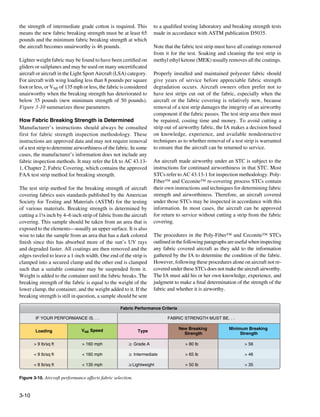
![Exposure to UV radiation appreciably reduces the strength of of maximum allowable degradation. If the tester does
polyester fabric and forms the basis of the Poly-Fiber™ and not puncture the fabric, it may be considered airworthy.
Ceconite™ fabric evaluation process. All approved covering Punctures near the breaking strength should be followed
systems utilize fill coats applied to the fabric to protect it from with further testing, specifically the strip breaking strength
UV. If installed according to the STC, these coatings should test described above. Usually, a puncture indicates the fabric
be sufficient to protect the fabric from the sun and should last is in need of replacement.
indefinitely. Therefore, most of the evaluation of the strength
of the fabric is actually an evaluation of the condition of its A second type of punch tester, the Seyboth, is not as popular
protective coating(s). as the Maule because it punctures a small hole in the fabric
when the mechanic pushes the shoulder of the testing unit
Upon a close visual inspection, the fabric coating(s) should against the fabric. A pin with a color-coded calibrated scale
be consistent, contain no cracks, and be flexible, not brittle. protrudes from the top of the tester and the mechanic reads
Pushing hard against the fabric with a knuckle should not this scale to determine fabric strength. Since this device
damage the coating(s). It is recommended the inspector requires a repair regardless of the strength of the fabric
check in several areas, especially those most exposed to the indicated, it is not widely used.
sun. Coatings that pass this test can move to a simple test
that determines whether or not UV light is passing through Seyboth and Maule fabric strength testers designed for
the coatings. cotton- and linen-covered aircraft, not to be used on modern
Dacron fabrics. Mechanical devices, combined with other
This test is based on the assumption that if visible light information and experience, help the FAA-certificated
passes through the fabric coatings, then UV light can also. To mechanic judge the strength of the fabric. [Figure 3-11]
verify whether or not visible light passes through the fabric
coating, remove an inspection panel from the wing, fuselage,
or empennage. Have someone hold an illuminated 60-watt Red
lamp one foot away from the exterior of the fabric. No light Yellow
should be visible through the fabric. If no light is visible, the Green
Maule tester
fabric has not been weakened by UV rays and can be assumed
to be airworthy. There is no need to perform the fabric strip
Seyboth or punch tester
strength test. If light is visible through the coatings, further
investigation is required.
25
30
Fabric Testing Devices
35
40
45
50
Mechanical devices used to test fabric by pressing against Calibrated scale
55
60
65
or piercing the finished fabric are not FAA approved and
70
75
80
are used at the discretion of the FAA-certificated mechanic E
L
U
to form an opinion on the general fabric condition. Punch
A
M
test accuracy depends on the individual device calibration, Fabric Fabric
total coating thickness, brittleness, and types of coatings
and fabric. If the fabric tests in the lower breaking strength
range with the mechanical punch tester or if the overall
Figure 3-11. Seyboth and Maule fabric strength testers.
fabric cover conditions are poor, then more accurate field
tests may be made.
General Fabric Covering Process
The test should be performed on exposed fabric where there It is required to have an IA involved in the process of re-
is a crack or chip in the coatings. If there is no crack or chip, covering a fabric aircraft because re-covering is a major repair
coatings should be removed to expose the fabric wherever or major alteration. Signatures are required on FAA Form
the test is to be done. 337 and in the aircraft logbook. To ensure work progresses
as required, the IA should be involved from the beginning,
The Maule punch tester, a spring-loaded device with its as well as at various stages throughout the process.
scale calibrated in breaking strength, tests fabric strength
by pressing against it while the fabric is still on the aircraft. This section describes steps common to various STC and
It roughly equates strength in pounds per square inch (psi) manufacturer covering processes, as well as the differences
of resistance to breaking strength. The tester is pushed of some processes. To aid in proper performance of fabric
squarely against the fabric until the scale reads the amount
3-11](https://image.slidesharecdn.com/faa-h-8083-31-amt-airframe-vol-1-130226145854-phpapp01/85/Faa-h-8083-31-amt-airframe-vol-1-155-320.jpg)
![covering and repair procedures, STC holders produce cover the aircraft. The envelopes must be sewn with approved
illustrated, step-by-step instructional manuals and videos that machine sewing thread, edge distance, fabric fold, etc., such
demonstrate the correct covering procedures. These training as those specified in AC 43.13-1 or an STC. Patterns are
aids are invaluable to the inexperienced technician. made and fabric is cut and stitched so that each major surface,
including the fuselage and wings, can be covered with a single,
Since modern fabric coverings last indefinitely, a rare close-fitting envelope. Since envelopes are cut to fit, they are
opportunity to inspect the aircraft exists during the re- slid into position, oriented with the seams in the proper place,
covering process. Inspectors and owner-operators should and attached with adhesive to the airframe. Envelope seams
use this opportunity to perform a thorough inspection of the are usually located over airframe structure in inconspicuous
aircraft before new fabric is installed. places, such as the trailing edge structures and the very top and
bottom of the fuselage, depending on airframe construction.
The method of fabric attachment should be identical, as far as Follow the manufacturer’s or STC’s instructions for proper
strength and reliability are concerned, to the method used by location of the sewn seams of the envelope when using this
the manufacturer of the aircraft being recovered or repaired. method. [Figure 3-13]
Carefully remove the old fabric from the airframe, noting the
location of inspection covers, drain grommets, and method
of attachment. Either the envelope method or blanket method
of fabric covering is acceptable, but a choice must be made
prior to beginning the re-covering process.
Blanket Method vs. Envelope Method
In the blanket method of re-covering, multiple flat sections
of fabric are trimmed and attached to the airframe. Certified
greige polyester fabric for covering an aircraft can be up to
70 inches in width and used as it comes off the bolt. Each
aircraft must be considered individually to determine the
size and layout of blankets needed to cover it. A single
blanket cut for each small surface (i.e., stabilizers and control Figure 3-13. A custom-fit presewn fabric envelope is slid into
surfaces) is common. Wings may require two blankets that position over a fuselage for the envelope method of fabric covering.
overlap. Fuselages are covered with multiple blankets that Other than fitting, most steps in the covering process are the same
span between major structural members, often with a single as with the blanket covering method.
blanket for the bottom. Very large wings may require more
than two blankets of fabric to cover the entire top and bottom Preparation for Fabric Covering Work
surfaces. In all cases, the fabric is adhered to the airframe Proper preparation for re-covering a fabric aircraft is
using the approved adhesives, following specific rules for the essential. First, assemble the materials and tools required to
covering process being employed. [Figure 3-12] complete the job. The holder of the STC usually supplies a
materials and tools list either separately or in the STC manual.
Control of temperature, humidity, and ventilation is needed
in the work environment. If ideal environmental conditions
cannot be met, additives are available that compensate for
this for most re-covering products.
Rotating work stands for the fuselage and wings provide
easy, alternating access to the upper and lower surfaces
while the job is in progress. [Figure 3-14] They can be
used with sawhorses or sawhorses can be used alone to
support the aircraft structure while working. A workbench
or table, as well as a rolling cart and storage cabinet, are also
Figure 3-12. Laying out fabric during a blanket method re-covering recommended. Figure 3-15 shows a well conceived fabric
job. covering workshop. A paint spray booth for sprayed-on
coatings and space to store components awaiting work is
An alternative method of re-covering, the envelope method, also recommended.
saves time by using precut and pre-sewn envelopes of fabric to
3-12](https://image.slidesharecdn.com/faa-h-8083-31-amt-airframe-vol-1-130226145854-phpapp01/85/Faa-h-8083-31-amt-airframe-vol-1-156-320.jpg)
![Rotatable wood stand and sawhorse Rotating stand and sawhorse
Figure 3-14. Rotating stands and sawhorses facilitate easy access to top and bottom surfaces during the fabric covering process.
Hazardous
material storage Shelving
Work bench
Tool
cart
Work area with rotating stands
Exhaust fan
Storage area
Fabric rack
Thermometer
Wash basin/water Fire extinguisher
+
FNCN
VOL BATT
PWR
−
SEL
emergency supplies
Figure 3-15. Some components of a work area for covering an aircraft with fabric.
Many of the substances used in most re-covering processes Removal of Old Fabric Coverings
are highly toxic. Proper protection must be used to avoid Removal of the old covering is the first step in replacing
serious short and long term adverse health effects. Eye an aircraft fabric covering. Cut away the old fabric from
protection, a proper respirator, and skin protection are the airframe with razor blades or utility knife. Care should
vital. As mentioned in the beginning of this chapter, nitrate be taken to ensure that no damage is done to the airframe.
dope is very flammable. Proper ventilation and a rated fire [Figure 3-16] To use the old covering for templates in
extinguisher should be on hand when working with this and transferring the location of inspection panels, cable guides,
other covering process materials. Grounding of work to and other features to the new covering, the old covering
prevent static electricity build-up may be required. All fabric should be removed in large sections. Note: any rib stitching
re-covering processes also involve multiple coats of various fasteners, if used to attach the fabric to the structure, should
products that are sprayed onto the fabric surface. Use of a be removed before the fabric is pulled free of the airframe. If
high-volume, low-pressure (HVLP) sprayer is recommended. fasteners are left in place, damage to the structure may occur
Good ventilation is needed for all of the processes. during fabric removal.
3-13](https://image.slidesharecdn.com/faa-h-8083-31-amt-airframe-vol-1-130226145854-phpapp01/85/Faa-h-8083-31-amt-airframe-vol-1-157-320.jpg)
![Carefully cut away the fabric.
Gently roll the fabric back as the cut is made.
Figure 3-16. Old fabric coverings are cut off in large pieces to preserve them as templates for locating various airframe features. Sharp
blades and care must be used to avoid damaging the structure.
Preparation of the Airframe Before Covering To obtain a smooth finish on fabric-covered leading edges
Once the old fabric has been removed, the exposed airframe of aluminum wings, a sheet of felt or polyester padding may
structure must be thoroughly cleaned and inspected. The be applied before the fabric is installed. This should only
IA collaborating on the job should be involved in this step be done with the material specified in the STC under which
of the process. Details of the inspection should follow the the technician is working. The approved padding ensures
manufacturer’s guidelines, the STC, or AC 43.13-1. All compatibility with the adhesives and first coatings of the
of the old adhesive must be completely removed from the covering process. When a leading edge pad is used, check the
airframe with solvent, such as MEK. A thorough inspection STC process instructions for permission to make a cemented
must be done and various components may be selected to be fabric seam over the padding. [Figure 3-17]
removed for cleaning, inspection, and testing. Any repairs
that are required, including the removal and treatment of all When completely cleaned, inspected, and repaired, an
corrosion, must be done at this time. If the airframe is steel approved primer, or varnish if it is a wood structure, should
tubing, many technicians take the opportunity to grit blast be applied to the airframe. This step is sometimes referred
the entire airframe at this stage. to as dope proofing. Exposed aluminum must first be acid
etched. Use the product(s) specified by the manufacturer
The leading edge of a wing is a critical area where airflow or in the STC to prepare the metal before priming. Two
diverges and begins its laminar flow over the wing’s surfaces, part epoxy primers and varnishes, which are not affected
which results in the generation of lift. It is beneficial to have by the fabric adhesive and subsequent coatings, are usually
a smooth, regular surface in this area. Plywood leading edges specified. One part primers, such as zinc chromate and spar
must be sanded until smooth, bare wood is exposed. If oil varnish, are typically not acceptable. The chemicals in the
or grease spots exist, they must be cleaned with naphtha or adhesives dissolve the primers, and adhesion of the fabric
other specified cleaners. If there are any chips, indentations, to the airframe is lost.
or irregularities, approved filler may be spread into these
areas and sanded smooth. The entire leading edge should be Sharp edges, metal seams, the heads of rivets, and any
cleaned before beginning the fabric covering process. other feature on the aircraft structure that might cut or wear
through the fabric should be covered with anti-chafe tape. As
3-14](https://image.slidesharecdn.com/faa-h-8083-31-amt-airframe-vol-1-130226145854-phpapp01/85/Faa-h-8083-31-amt-airframe-vol-1-158-320.jpg)
![Figure 3-17. The use of specified felt or padding over the wing
leading edges before the fabric is installed results in a smooth Figure 3-18. Anti-chafe tape is applied to all features that might
regular surface. cut or wear through the fabric.
described above, this cloth sticky-back tape is approved and
should not be substituted with masking or any other kind of
tape. Sometimes, rib cap strips need to have anti-chafe tape
applied when the edges are not rounded over. [Figure 3-18]
Inter-rib bracing must also be accomplished before the fabric
is installed. It normally does not have an adhesive attached to
it and is wrapped only once around each rib. The single wrap
around each rib is enough to hold the ribs in place during
the covering process but allows small movements during the
fabric shrinking process. [Figure 3-19]
Attaching Polyester Fabric to the Airframe
Inexperienced technicians are encouraged to construct a
test panel upon which they can practice with the fabric and
various substances and techniques to be used on the aircraft.
It is often suggested to cover smaller surfaces first, such as
the empennage and control surfaces. Mistakes on these can
be corrected and are less costly if they occur. The techniques
employed for all surfaces, including the wings and fuselage,
are basically the same. Once dexterity has been established,
the order in which one proceeds is often a personal choice.
When the airframe is primed and ready for fabric installation,
Figure 3-19. Inter-rib bracing holds the ribs in place during the
it must receive a final inspection by an A&P with IA.
re-covering process.
3-15](https://image.slidesharecdn.com/faa-h-8083-31-amt-airframe-vol-1-130226145854-phpapp01/85/Faa-h-8083-31-amt-airframe-vol-1-159-320.jpg)
![When approved, attachment of the fabric may begin. The final appearance of the covering job should be considered.
manufacturer’s or STC’s instructions must be followed For example, fabric seams made on the wing’s top surface
without deviation for the job to be airworthy. The following of a high wing aircraft are not visible when approaching the
are the general steps taken. Each approved process has its aircraft. Seams on low wing aircraft and many horizontal
own nuances. stabilizers are usually made on the bottom of the wing for
the same reason. [Figure 3-20]
Seams
During installation, the fabric is overlapped and seamed Fabric Cement
together. Primary concerns for fabric seams are strength, A polyester fabric covering is cemented or glued to the
elasticity, durability, and good appearance. Whether using the airframe structure at all points where it makes contact. Special
blanket method or envelope method, position all fabric seams formula adhesives have replaced nitrate dope for adhesion
over airframe structure to which the fabric is to be adhered in most covering processes. The adhesive (as well as all
during the covering process, whenever possible. Unlike the subsequent coating materials) should be mixed for optimum
blanket method, fabric seam overlap is predetermined in the characteristics at the temperature at which the work is being
envelope method. Seams sewn to the specifications in AC performed. Follow the manufacturer’s or STC’s guidance
43.13-1, the STC under which the work is being performed, when mixing.
or the manufacturer’s instructions should perform adequately.
To attach the fabric to the airframe, first pre-apply two coats
Most covering procedures for polyester fabric rely on doped of adhesive to the structure at all points the fabric is to contact
or glued seams as opposed to sewn seams. They are simple it. (It is important to follow the manufacturer’s or STC’s
and easy to make and provide excellent strength, elasticity, guidance as all systems are different.) Allow these to dry.
durability, and appearance. When using the blanket method, The fabric is then spread over the surface and clamped into
seam overlap is specified in the covering instructions and position. It should not be pulled tighter than the relaxed but
the FAA-certificated A&P mechanic must adhere to these not wrinkled condition it assumes when lying on the structure.
specifications. Typically, a minimum of two to four inches Clamps or clothespins are used to attach the fabric completely
of fabric overlap seam is required where ends of fabric are around the perimeter. The Stewart System STC does not
joined in areas of critical airflow, such as the leading edge of need clamps because the glue assumes a tacky condition
a wing. One to two inches of overlap is often the minimum when precoated and dried. There is sufficient adhesion in
in other areas. the precoat to position the fabric.
When using the blanket method, options exist for deciding The fabric should be positioned in all areas before undertaking
where to overlap the fabric for coverage. Function and the final adhesion. Final adhesion often involves lifting the fabric,
Fabric overlap covering a low wing aircraft
Top fabric
2" typical overlap on the leading edge
Bottom fabric
1" typical overlap on the trailing edge
Fabric overlap covering a high wing aircraft
2" typical overlap on the leading edge
Top fabric
Bottom fabric
1" typical overlap on the trailing edge
Figure 3-20. For appearance, fabric can be overlapped differently on high wing and low wing aircraft.
3-16](https://image.slidesharecdn.com/faa-h-8083-31-amt-airframe-vol-1-130226145854-phpapp01/85/Faa-h-8083-31-amt-airframe-vol-1-160-320.jpg)
![applying a wet bed of cement, and pressing the fabric into the
bed. An additional coat of cement over the top of the fabric
is common. Depending on the process, wrinkles and excess
cement are smoothed out with a squeegee or are ironed out.
The Stewart System calls for heat activation of the cement
precoats through the fabric with an iron while the fabric is
in place. Follow the approved instructions for the covering
method being used.
Fabric Heat Shrinking
Once the fabric has been glued to the structure, it can be
made taut by heat shrinking. This process is done with an
ordinary household iron that the technician calibrates before
use. A smaller iron is also used to iron in small or tight places.
[Figure 3-21] The iron is run over the entire surface of the
fabric. Follow the instructions for the work being performed.
Some processes avoid ironing seams while other processes
begin ironing over structure and move to spanned fabric or
visa-versa. It is important to shrink the fabric evenly. Starting
on one end of a structure and progressing sequentially to the
other end is not recommended. Skipping from one end to the
other, and then to the middle, is more likely to evenly draw
Figure 3-21. Irons used during the fabric covering process.
the fabric tight. [Figure 3-22]
process has its own temperature regime for the stages of
The amount polyester fabric shrinks is directly related to tautening. Typically ranging from 225 °F to 350 °F, it is
the temperature applied. Polyester fabric can shrink nearly imperative to follow the process instructions. Not all fabric
5 percent at 250 °F and 10 percent at 350 °F. It is customary covering processes use the same temperature range and
to shrink the fabric in stages, using a lower temperature first, maximum temperature. Ensure irons are calibrated to prevent
before finishing with the final temperature setting. The first damage at high temperature settings.
shrinking is used to remove wrinkles and excess fabric. The
final shrinking gives the finished tautness desired. Each
side
from side to
3 Switch 2 Move to the opposite side
4 End in the middle
1 Begin on one end
Figure 3-22. An example of a wing fabric ironing procedure designed to evenly taughten the fabric.
3-17](https://image.slidesharecdn.com/faa-h-8083-31-amt-airframe-vol-1-130226145854-phpapp01/85/Faa-h-8083-31-amt-airframe-vol-1-161-320.jpg)
![Attaching Fabric to the Wing Ribs Holes are laid out and pre-punched through the skin as
Once the fabric has been tautened, covering processes vary. close to the rib caps as possible to accept the lacing cord.
Some require a sealing coat be applied to the fabric at this [Figure 3-24] This minimizes leverage the fabric could
point. It is usually put on by brush to ensure the fibers are develop while trying to pull away from the structure and
saturated. Other processes seal the fabric later. Whatever prevents tearing. The location of the holes is not arbitrary.
the process, the fabric on wings must be secured to the wing The spacing between lacing holes and knots must adhere
ribs with more than just cement. The forces caused by the to manufacturer’s instructions, if available. STC lacing
airflow over the wings are too great for cement alone to hold guidance refers to manufacturer’s instructions or to that
the fabric in place. As described in the materials section, shown on the chart in Figure 3-25 which is taken from AC
screws, rivets, clips and lacing hold the fabric in place on 43.13-1. Notice that because of greater turbulence in the area
manufactured aircraft. Use the same attach method as used of the propeller wash, closer spacing between the lacing is
by the original aircraft manufacturer. Deviation requires a required there. This slipstream is considered to be the width
field approval. Note that fuselage and empennage attachments of the propeller plus one additional rib. Ribs are normally
may be used on some aircraft. Follow the methodology for laced from the leading edge to the trailing edge of the wing.
wing rib lacing described below and the manufacturer’s Rib lacing is done with a long curved needle to guide the
instructions for attach point locations and any possible cord in and out of holes and through the depth of the rib.
variations to what is presented here. The knots are designed not to slip under the forces applied
and can be made in a series out of a single strand of lacing.
Care must always be taken to identify and eliminate any sharp Stitching can begin at the leading edge or trailing edge. A
edges that might wear through the fabric. Reinforcing tape of square knot with a half hitch on each side is typically used
the exact same width as the rib cap is installed before any of for the first knot when lacing a rib. [Figure 3-26] This is
the fasteners. This approved sticky-back tape helps prevent followed by a series of modified seine knots until the final
the fabric from tearing. [Figure 3-23] Then, screws, rivets, knot is made and secured with a half hitch. [Figure 3-27]
and clips simply attach into the predrilled holes in the rib caps Hidden modified seine knots are also used. These knots are
to hold the fabric to the caps. Rib lacing is a more involved placed below the fabric surface so only a single strand of
process whereby the fabric is attached to the ribs with cord. lacing is visible across the rib cap. [Figure 3-28]
Figure 3-23. Reinforcing tape the same width as the wing ribs is Figure 3-24. A premarked location for a lacing hole, which is
applied over all wing ribs. punched through the fabric with a pencil.
Rib Lacing Structure and accessories within the wing may prevent a
There are two kinds of rib lacing cord. One has a round continuous lacing. Ending the lacing and beginning again
cross-section and the other flat. Which to use is a matter can avoid these obstacles. Lacing that is not long enough to
of preference based on ease of use and final appearance. complete the rib may be ended and a new starting knot can
Only approved rib lacing cord can be used. Unless a rib is be initiated at the next set of holes. The lacing can also be
unusually deep from top to bottom, rib lacing uses a single extended by joining it with another piece of lacing using the
length of cord that passes completely through the wing from splice knot shown in Figure 3-29.
the upper surface to the lower surface thereby attaching the
top and bottom skin to the rib simultaneously.
3-18](https://image.slidesharecdn.com/faa-h-8083-31-amt-airframe-vol-1-130226145854-phpapp01/85/Faa-h-8083-31-amt-airframe-vol-1-162-320.jpg)
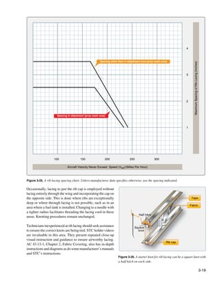
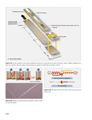
![Rings, Grommets, and Gussets
When the ribs are laced and the fabric covering completely
attached, the various inspection rings, drain grommets,
reinforcing patches, and finishing tapes are applied. Inspection
rings aid access to critical areas of the structure (pulleys, bell
cranks, drag/anti-drag wires, etc.) once the fabric skin is in
place. They are plastic or aluminum and normally cemented
to the fabric using the approved cement and procedures. The
area inside the ring is left intact. It is removed only when
inspection or maintenance requires access through that ring.
Once removed, preformed inspection panels are used to close
the opening. The rings should be positioned as specified by
the manufacturer. Lacking that information, they should be Figure 3-31. Drain grommets cemented into place on the bottom
positioned as they were on the previous covering fabric. side of a control surface.
Additional rings should be installed by the technician if it is
determined a certain area would benefit from access in the aircraft. Check the Airworthiness Directives (ADs) and
future. [Figure 3-30] Service Bulletins for the aircraft being re-covered to ensure
required rings and grommets have been installed.
Cable guide openings, strut-attach fitting areas, and similar
features, as well as any protrusions in the fabric covering, are
reinforced with fabric gussets. These are installed as patches
in the desired location. They should be cut to fit exactly
around the feature they reinforce to support the original
opening made in the covering fabric. [Figure 3-32] Gussets
made to keep protrusions from coming through the fabric
should overlap the area they protect. Most processes call for
the gusset material to be preshrunk and cemented into place
using the approved covering process cementing procedures.
Finishing Tapes
Figure 3-30. This inspection ring was cemented into place on the Finishing tapes are applied to all seams, edges, and over the
fabric covering. The approved technique specifies the use of a fabric ribs once all of the procedures above have been completed.
overlay that is cemented over the ring and to the fabric. They are used to protect these areas by providing smooth
aerodynamic resistance to abrasion. The tapes are made from
Water from rain and condensation can collect under the fabric the same polyester material as the covering fabric. Use of
covering and needs a way to escape. Drain grommets serve lighter weight tapes is approved in some STCs. Preshrunk
this purpose. There are a few different types as described in tapes are preferred because they react to exposure to the
the materials section above. All are cemented into position environment in the same way the as the fabric covering.
in accordance with the approved process under which the This minimizes stress on the adhesive joint between the two.
work is being performed. Locations for the drain grommets Straight edged and pinked tapes are available. The pinking
should be ascertained from manufacturer’s data. If not provides greater surface area for adhesion of the edges and
specified, AC 43.13-1 has acceptable location information. a smoother transition into the fabric covering. Only tapes
Each fabric covering STC may also give recommendations. approved in the STC under which work is being accomplished
Typically, drain grommets are located at the lowest part may be used to be considered airworthy.
of each area of the structure (e.g., bottom of the fuselage,
wings, empennage). [Figure 3-31] Each rib bay of the wings Finishing tapes from one to six inches in width are used.
is usually drained with one or two grommets on the bottom Typically, two inch tapes cover the rib lacing and fuselage
of the trailing edge. Note that drain holes without grommets seams. Wing leading edges usually receive the widest tape
are sometimes approved in reinforced fabric. with four inches being common. [Figure 3-33] Bias cut tapes
are often used to wrap around the curved surfaces of the
It is possible that additional inspection rings and drain airframe, such as the wing tips and empennage surface edges.
grommets have been specified after the manufacture of the They lay flat around the curves and do not require notching.
3-21](https://image.slidesharecdn.com/faa-h-8083-31-amt-airframe-vol-1-130226145854-phpapp01/85/Faa-h-8083-31-amt-airframe-vol-1-165-320.jpg)
![fibers in the polyester fabric, forming a barrier that keeps
water and contaminants from reaching the fabric during
its life. It is also used to provide adhesion of subsequent
coatings. Usually brushed on in a cross coat application for
thorough penetration, two coats of sealer are commonly used
but processes vary on how many coats and whether spray
coating is permitted.
With the sealer coats installed and dried, the next step
provides protection from UV light, the only significant cause
of deterioration of polyester fabric. Designed to prevent UV
light from reaching the fabric and extend the life of the fabric
indefinitely, these coating products, or fill coats, contain
aluminum solids premixed into them that block the UV rays.
They are sprayed on in the number of cross coats as specified
in the manufacturer’s STC or AC 43.13-1 instructions under
which work is done. Two to four cross coats is common.
Note that some processes may require coats of clear butyrate
before the blocking formula is applied.
Fabric primer is a coating used in some approved covering
processes that combines the sealer and fill coatings into one.
Applied to fabric after the finishing tapes are installed, these
Figure 3-32. A strut fitting and cable guide with reinforcing fabric
fabric primers surround and seal the fabric fibers, provide
gussets cemented in place.
good adhesion for all of the following coatings, and contain
UV blocking agents. One modern primer contains carbon
solids and others use chemicals that work similarly to sun
block for human skin. Typically, two to four coats of fabric
primer are sufficient before the top coatings of the final finish
are applied. [Figure 3-34]
Figure 3-33. Cement is brushed through a four-inch tape during
installation over the fabric seam on a wing leading edge. Two-inch
tapes cover the wing ribs and rib lacing.
Finishing tapes are attached with the process adhesive or
the nitrate dope sealer when using a dope-based process.
Generally, all chordwise tapes are applied first followed by
the span-wise tapes at the leading and trailing edges. Follow
the manufacturer’s STC or AC 43.13-1 instructions.
Figure 3-34. Applying a primer with UV blocking by spraying
Coating the Fabric
cross coats.
The sealer coat in most fabric covering processes is applied
after all finishing tapes have been installed unless it was The FAA-certificated mechanic must strictly adhere to all
applied prior to rib lacing as in a dope-based finishing instructions for thinning, drying times, sanding, and cleaning.
process. This coat saturates and completely surrounds the Small differences in the various processes exist and what
3-22](https://image.slidesharecdn.com/faa-h-8083-31-amt-airframe-vol-1-130226145854-phpapp01/85/Faa-h-8083-31-amt-airframe-vol-1-166-320.jpg)
![works in one process may not be acceptable and could ruin is possible to apply the sewing repair techniques outlined
the finish of another process. STCs are issued on the basis in AC 43.13-1 to polyester fabric, but they were developed
of the holder having successfully proven the effectiveness of primarily for cotton and linen fabrics. STC instructions for
both the materials and the techniques involved. repairs to polyester fabric are for cemented repairs which
most technicians prefer as they are generally considered
When the fill coats have been applied, the final appearance easier than sewn repairs. There is no compromise to the
of the fabric covering job is crafted with the application strength of the fabric with either method.
of various topcoats. Due to the chemical nature of the fill
coating upon which topcoats are sprayed, only specified Patching or replacing a section of the covering requires
materials can be used for top coating to ensure compatibility. prepping the fabric area around the damage where new
Colored butyrate dope and polyurethane paint finishes are fabric is to be attached. Procedures vary widely. Dope-based
most common. They are sprayed on according to instructions. covering systems tend toward stripping off all coatings to
cement raw fabric to raw fabric when patching or seaming
Once the topcoats are dry, the trim (N numbers, stripes, in a new panel. From this point, the coatings are reapplied
etc.) can be added. Strict observation of drying times and and finished as in the original covering process. Some
instructions for buffing and waxing are critical to the quality polyurethane-based coating processes require only a scuffing
of the final finish. Also, note that STC instructions may of the topcoat with sandpaper before adhering small patches
include insight on finishing the nonfabric portions of the that are then refinished. [Figure 3-35] Still, other processes
airframe to best match the fabric covering finish. may remove the topcoats and cement a patch into the sealer
or UV blocking coating. In some repair processes, preshrunk
Polyester Fabric Repairs fabric is used and in others, the fabric is shrunk after it is in
Applicable Instructions place. Varying techniques and temperatures for shrinking
Repairs to aircraft fabric coverings are inevitable. Always and gluing the fabric into a repair also exist.
inspect a damaged area to ensure the damage is confined
to the fabric and does not involve the structure below. A These deviations in procedures underscore the critical nature
technician who needs to make a fabric repair must first of identifying and strictly adhering to the correct instructions
identify which approved data was used to install the covering from the approved data for the fabric covering in need of
that needs to be repaired. Consult the logbook where an repair. A patch or panel replacement technique for one
entry and reference to manufacturer data, an STC, or a field covering system could easily create an unairworthy repair
approval possibly utilizing practices from AC 43.13-1 should if used on fabric installed with a different covering process.
be recorded. The source of approved data for the covering
job is the same source of approved data used for a repair. Large section panel repairs use the same proprietary adhesives
and techniques and are only found in the instructions for
This section discusses general information concerning repairs the process used to install the fabric covering. A common
to polyester fabric. Thorough instructions for repairs made to technique for replacing any large damaged area is to replace
cotton covered aircraft can be found in AC 43.13-1. It is the all of the fabric between two adjacent structural members
responsibility of the holder of an STC to provide maintenance (e.g., two ribs, two longerons, between the forward and rear
instructions for the STC alteration in addition to materials spars). Note that this is a major repair and carries with it the
specifications required to do the job. requirement to file an FAA Form 337.
Repair Considerations Cotton-Covered Aircraft
The type of repair performed depends on the extent of the You may encounter a cotton fabric-covered aircraft. In
damage and the process under which the fabric was installed. addition to other airworthiness criterion, the condition of the
The size of the damaged area is often a reference for whether fabric under the finished surface is paramount as the cotton
a patch is sufficient to do the repair or whether a new panel can deteriorate even while the aircraft is stored in a hanger.
should be installed. Repair size may also dictate the amount of Inspection, in accordance with the manufacturer maintenance
fabric-to-fabric overlap required when patching and whether manual or AC 43.13-1, should be diligent. If the cotton
finishing tapes are required over the patch. Many STC repair covering is found to be airworthy, repairs to the fabric can
procedures do not require finishing tapes. Some repairs in be made under those specifications. This includes sewn-in
AC 43.13-1 require the use of tape up to six inches wide. and doped-in patches, as well as sewn-in and doped-in panel
repairs. Due to the very limited number of airworthy aircraft
While many cotton fabric repairs involve sewing, nearly that may still be covered with cotton, this handbook does
all repairs of polyester fabric are made without sewing. It not cover specific information on re-covering with cotton or
3-23](https://image.slidesharecdn.com/faa-h-8083-31-amt-airframe-vol-1-130226145854-phpapp01/85/Faa-h-8083-31-amt-airframe-vol-1-167-320.jpg)
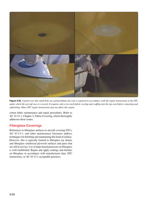
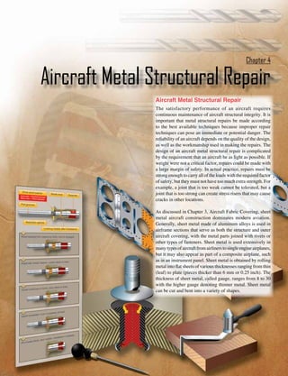
![Damage to metal aircraft structures is often caused by accept the stresses, carry them across the repair, and then
corrosion, erosion, normal stress, and accidents and mishaps. transfer them back into the original structure. These stresses
Sometimes aircraft structure modifications require extensive are considered as flowing through the structure, so there
structural rework. For example, the installation of winglets must be a continuous path for them, with no abrupt changes
on aircraft not only replaces a wing tip with a winglet, but in cross-sectional areas along the way. Abrupt changes in
also requires extensive reinforcing of the wing structure to cross-sectional areas of aircraft structure that are subject to
carry additional stresses. cycle loading or stresses result in a stress concentration that
may induce fatigue cracking and eventual failure. A scratch or
Numerous and varied methods of repairing metal structural gouge in the surface of a highly stressed piece of metal causes
portions of an aircraft exist, but no set of specific repair a stress concentration at the point of damage and could lead
patterns applies in all cases. The problem of repairing a to failure of the part. Forces acting on an aircraft, whether it
damaged section is usually solved by duplicating the original is on the ground or in flight, introduce pulling, pushing, or
part in strength, kind of material, and dimensions. To make a twisting forces within the various members of the aircraft
structural repair, the aircraft technician needs a good working structure. While the aircraft is on the ground, the weight of
knowledge of sheet metal forming methods and techniques. In the wings, fuselage, engines, and empennage causes forces
general, forming means changing the shape by bending and to act downward on the wing and stabilizer tips, along the
forming solid metal. In the case of aluminum, this is usually spars and stringers, and on the bulkheads and formers. These
done at room temperature. All repair parts are shaped to fit in forces are passed from member to member causing bending,
place before they are attached to the aircraft or component. twisting, pulling, compression, and shearing forces.
Forming may be a very simple operation, such as making As the aircraft takes off, most of the forces in the fuselage
a single bend or a single curve, or it may be a complex continue to act in the same direction; because of the motion
operation, requiring a compound curvature. Before forming of the aircraft, they increase in intensity. The forces on the
a part, the aircraft technician must give some thought to wingtips and the wing surfaces, however, reverse direction;
the complexity of the bends, the material type, the material instead of being downward forces of weight, they become
thickness, the material temper, and the size of the part being upward forces of lift. The forces of lift are exerted first
fabricated. In most cases, these factors determine which against the skin and stringers, then are passed on to the ribs,
forming method to use. Types of forming discussed in this and finally are transmitted through the spars to be distributed
chapter include bending, brake forming, stretch forming, roll through the fuselage. The wings bend upward at their ends
forming, and spinning. The aircraft technician also needs and may flutter slightly during flight. This wing bending
a working knowledge of the proper use of the tools and cannot be ignored by the manufacturer in the original design
equipment used in forming metal. and construction and cannot be ignored during maintenance.
It is surprising how an aircraft structure composed of
In addition to forming techniques, this chapter introduces structural members and skin rigidly riveted or bolted together,
the airframe technician to the tools used in sheet metal such as a wing, can bend or act so much like a leaf spring.
construction and repair, structural fasteners and their
installation, how to inspect, classify, and assess metal The six types of stress in an aircraft are described as tension,
structural damage, common repair practices, and types of compression, shear, bearing, bending, and torsion (or
repairs. twisting). The first four are commonly called basic stresses;
the last two, combination stresses. Stresses usually act in
The repairs discussed in this chapter are typical of those used combinations rather than singly. [Figure 4-1]
in aircraft maintenance and are included to introduce some of
the operations involved. For exact information about specific Tension
repairs, consult the manufacturer’s maintenance or structural Tension is the stress that resists a force that tends to pull apart.
repair manuals (SRM). General repair instructions are also The engine pulls the aircraft forward, but air resistance tries
discussed in Advisory Circular (AC) 43.13.1, Acceptable to hold it back. The result is tension, which tends to stretch
Methods, Techniques, and Practices—Aircraft Inspection the aircraft. The tensile strength of a material is measured in
and Repair. pounds per square inch (psi) and is calculated by dividing
the load (in pounds) required to pull the material apart by its
Stresses in Structural Members cross-sectional area (in square inches).
An aircraft structure must be designed so that it accepts all of
the stresses imposed upon it by the flight and ground loads The strength of a member in tension is determined on
without any permanent deformation. Any repair made must the basis of its gross area (or total area), but calculations
4-2](https://image.slidesharecdn.com/faa-h-8083-31-amt-airframe-vol-1-130226145854-phpapp01/85/Faa-h-8083-31-amt-airframe-vol-1-170-320.jpg)
![Compression
Compression, the stress that resists a crushing force, tends to
shorten or squeeze aircraft parts. The compressive strength of
a material is also measured in psi. Under a compressive load,
an undrilled member is stronger than an identical member
with holes drilled through it. However, if a plug of equivalent
or stronger material is fitted tightly in a drilled member, it
transfers compressive loads across the hole, and the member
A. Tension carries approximately as large a load as if the hole were not
there. Thus, for compressive loads, the gross or total area may
be used in determining the stress in a member if all holes are
tightly plugged with equivalent or stronger material.
Shear
Shear is the stress that resists the force tending to cause one
layer of a material to slide over an adjacent layer. Two riveted
plates in tension subject the rivets to a shearing force. Usually,
B. Compression the shear strength of a material is either equal to or less than
its tensile or compressive strength. Shear stress concerns the
aviation technician chiefly from the standpoint of the rivet
and bolt applications, particularly when attaching sheet metal,
because if a rivet used in a shear application gives way, the
riveted or bolted parts are pushed sideways.
Bearing
Bearing stress resists the force that the rivet or bolt places
C. Torsion on the hole. As a rule, the strength of the fastener should be
such that its total shear strength is approximately equal to
the total bearing strength of the sheet material. [Figure 4-2]
Top sheet is bearing against
Bearing stress
the bottom sheet. Fasteners The force that
are pressing top sheet against tries to pull the
bottom bearing two sheets apart
D. Shear
Tension
Rivets
Compression
Figure 4-2. Bearing stress.
E. Bending
Torsion
Figure 4-1. Stresses in aircraft structures.
Torsion is the stress that produces twisting. While moving
involving tension must take into consideration the net area of the aircraft forward, the engine also tends to twist it to one
the member. Net area is defined as the gross area minus that side, but other aircraft components hold it on course. Thus,
removed by drilling holes or by making other changes in the torsion is created. The torsional strength of a material is its
section. Placing rivets or bolts in holes makes no appreciable resistance to twisting or torque (twisting stress). The stresses
difference in added strength, as the rivets or bolts will not arising from this action are shear stresses caused by the
transfer tensional loads across holes in which they are inserted. rotation of adjacent planes past each other around a common
4-3](https://image.slidesharecdn.com/faa-h-8083-31-amt-airframe-vol-1-130226145854-phpapp01/85/Faa-h-8083-31-amt-airframe-vol-1-171-320.jpg)
![reference axis at right angles to these planes. This action may
be illustrated by a rod fixed solidly at one end and twisted 8 THS
by a weight placed on a lever arm at the other, producing the 16 THS 1 2 3 4 5
equivalent of two equal and opposite forces acting on the rod
at some distance from each other. A shearing action is set up
all along the rod, with the center line of the rod representing
the neutral axis.
28 4 8 12 16 20 24 28 4
4 8 12 16 20 24 28 4 8 12 16 20 24 28 4 8 12 16 20 24 28
Bending 32 MOS
64 THS
8 16 24 32 40 48 56
1 2 3 4 8 16 24 32 40 48 56 5 8 16 24 32 40 48 56
Bending (or beam stress) is a combination of compression 56 8 16 24 32 40 48 56 8
and tension. The rod in Figure 4-1E has been shortened
(compressed) on the inside of the bend and stretched on
the outside of the bend. Note that the bending stress causes
a tensile stress to act on the upper half of the beam and a
compressive stress on the lower half. These stresses act in
opposition on the two sides of the center line of the member,
9 1 2 3 4 5 6 7 8 9 1
which is called the neutral axis. Since these forces acting in 1 2 3 4 5 6 7 8 9 1 2 3 4 5 6 7 8 9 1 2 3 4 5 6 7 8 9
opposite directions are next to each other at the neutral axis,
10 THS
100 THS
1 2 3 4
5
6 7 8 9
1
1 2 3 4
5
6 7 8 9
2 3 5
4 5
1 2 3 4
5
6 7 8 9
9 1 2 3 4 6 7 8 9 1
the greatest shear stress occurs along this line, and none exists
at the extreme upper or lower surfaces of the beam.
Tools for Sheet Metal Construction and
Repair
Figure 4-3. Scales.
Without modern metalworking tools and machines, the
job of the airframe technician would be more difficult and measure any angle between the head and the blade, and a
tiresome, and the time required to finish a task would be center head that uses one side of the blade as the bisector of
much greater. These specialized tools and machines help the a 90° angle. The center of a shaft can be found by using the
airframe technician construct or repair sheet metal in a faster, center head. Place the end of the shaft in the V of the head
simpler, and better manner than possible in the past. Powered and scribe a line along the edge of the scale. Rotate the head
by human muscle, electricity, or compressed air, these tools about 90° and scribe another line along the edge of the scale.
are used to lay out, mark, cut, sand, or drill sheet metal. The two lines will cross at the center of the shaft. [Figure 4-4]
Layout Tools Dividers
Before fitting repair parts into an aircraft structure, the new Dividers are used to transfer a measurement from a device
sections must be measured and marked, or laid out to the to a scale to determine its value. Place the sharp points at
dimensions needed to make the repair part. Tools utilized the locations from which the measurement is to be taken.
for this process are discussed in this section. Then, place the points on a steel machinist’s scale, but put
one of the points on the 1-inch mark and measure from there.
Scales [Figure 4-5]
Scales are available in various lengths, with the 6-inch and
12-inch scales being the most common and affordable. A Rivet Spacers
scale with fractions on one side and decimals on the other side A rivet spacer is used to make a quick and accurate rivet
is very useful. To obtain an accurate measurement, measure pattern layout on a sheet. On the rivet spacer, there are
with the scale held on edge from the 1-inch mark instead of alignment marks for 1⁄2-inch, 3⁄4-inch, 1-inch and 2-inch rivet
the end. Use the graduation marks on the side to set a divider spacing. [Figure 4-6]
or compass. [Figure 4-3]
Marking Tools
Combination Square Pens
A combination square consists of a steel scale with three Fiber-tipped pens are the preferred method of marking
heads that can be moved to any position on the scale and lines and hole locations directly on aluminum, because the
locked in place. The three heads are a stock head that graphite in a No. 2 pencil can cause corrosion when used on
measures 90° and 45° angles, a protractor head that can
4-4](https://image.slidesharecdn.com/faa-h-8083-31-amt-airframe-vol-1-130226145854-phpapp01/85/Faa-h-8083-31-amt-airframe-vol-1-172-320.jpg)
![Scriber
Level
90
180
0
2 3 4 5 8 9 10 11
Stock head Protractor head Center head
Figure 4-4. Combination square.
Scribes
A scribe is a pointed instrument used to mark or score metal
to show where it is to be cut. A scribe should only be used
when marks will be removed by drilling or cutting because
it makes scratches that weaken the material and could cause
corrosion. [Figure 4-7]
Figure 4-5. Divider.
Figure 4-7. Scribe.
Punches
Punches are usually made of carbon steel that has been
hardened and tempered. Generally classified as solid or
hollow, punches are designed according to their intended
use. A solid punch is a steel rod with various shapes at the
end for different uses. For example, it is used to drive bolts
Figure 4-6. Rivet spacer.
out of holes, loosen frozen or tight pins and keys, knock out
aluminum. Make the layout on the protective membrane if it rivets, pierce holes in a material, etc. The hollow punch is
is still on the material, or mark directly on the material with sharp edged and used most often for cutting out blanks. Solid
a fiber-tipped pen, such as a fine-point Sharpie®, or cover punches vary in both size and point design, while hollow
the material with masking tape and then mark on the tape. punches vary in size.
4-5](https://image.slidesharecdn.com/faa-h-8083-31-amt-airframe-vol-1-130226145854-phpapp01/85/Faa-h-8083-31-amt-airframe-vol-1-173-320.jpg)
![Prick Punch Automatic Center Punch
A prick punch is primarily used during layout to place The automatic center punch performs the same function as an
reference marks on metal because it produces a small ordinary center punch, but uses a spring tension mechanism
indentation. [Figure 4-8] After layout is finished, the to create a force hard enough to make an indentation without
indentation is enlarged with a center punch to allow for the need for a hammer. The mechanism automatically strikes
drilling. The prick punch can also be used to transfer a blow of the required force when placed where needed and
dimensions from a paper pattern directly onto the metal. pressed. This punch has an adjustable cap for regulating
Take the following precautions when using a prick punch: the stroke; the point can be removed for replacement or
• Never strike a prick punch a heavy blow with a sharpening. Never strike an automatic center punch with a
hammer because it could bend the punch or cause hammer. [Figure 4-10]
excessive damage to the item being worked.
• Do not use a prick punch to remove objects from holes
because the point of the punch spreads the object and
causes it to bind even more.
Figure 4-10. Automatic center punch.
Transfer Punch
A transfer punch uses a template or existing holes in the
Figure 4-8. Prick punch.
structure to mark the locations of new holes. The punch is
centered in the old hole over the new sheet and lightly tapped
Center Punch
with a mallet. The result should be a mark that serves to locate
A center punch is used to make indentations in metal as an the hole in the new sheet. [Figure 4-11]
aid in drilling. [Figure 4-9] These indentations help the drill,
which has a tendency to wander on a flat surface, stay on
the mark as it goes through the metal. The traditional center
punch is used with a hammer, has a heavier body than the
Transfer punch
prick punch, and has a point ground to an angle of about 60°.
Take the following precautions when using a center punch:
• Never strike the center punch with enough force to
dimple the item around the indentation or cause the Use old skin as template
metal to protrude through the other side of the sheet.
• Do not use a center punch to remove objects from holes
because the point of the punch spreads the object and
causes it to bind even more.
New skin
Figure 4-11. Transfer punch.
Drive Punch
The drive punch is made with a flat face instead of a point
because it is used to drive out damaged rivets, pins, and
bolts that sometimes bind in holes. The size of the punch
Figure 4-9. Center punch.
is determined by the width of the face, usually 1⁄8-inch to
1
⁄4-inch. [Figure 4-12]
4-6](https://image.slidesharecdn.com/faa-h-8083-31-amt-airframe-vol-1-130226145854-phpapp01/85/Faa-h-8083-31-amt-airframe-vol-1-174-320.jpg)
![Awl
A pointed tool for marking surfaces or for punching small
holes, an awl is used in aircraft maintenance to place scribe
marks on metal and plastic surfaces and to align holes, such
as in the installation of a deicer boot. [Figure 4-15]
Figure 4-12. Drive punch.
Pin Punch
The pin punch typically has a straight shank characterized
by a hexagonal body. Pin punch points are sized in 1⁄32-inch
increments of an inch and range from 1⁄16-inch to 3⁄8-inch in
diameter. The usual method for driving out a pin or bolt is
to start working it out with a drive punch until the shank of Figure 4-15. Awl.
the punch is touching the sides of the hole. Then use a pin
punch to drive the pin or bolt the rest of the way out of the Procedures for one use of an awl:
hole. [Figure 4-13] 1. Place the metal to be scribed on a flat surface. Place
a ruler or straightedge on the guide marks already
measured and placed on the metal.
2. Remove the protective cover from the awl.
3. Hold the straightedge firmly. Hold the awl, as shown
in Figure 4-16, and scribe a line along the straightedge.
4. Replace the protective cover on the awl.
Figure 4-13. Pin punch.
1
2
Chassis Punch
3
A chassis punch is used to make holes in sheet metal parts for
4
the installation of instruments and other avionics appliance,
5
6
as well as lightening holes in ribs and spars. Sized in 1⁄16 of
7
an inch, they are available in sizes from 1⁄2 inch to 3 inches.
8
[Figure 4-14]
9
10
11
12
Figure 4-16. Awl usage.
Figure 4-14. Chassis punch.
4-7](https://image.slidesharecdn.com/faa-h-8083-31-amt-airframe-vol-1-130226145854-phpapp01/85/Faa-h-8083-31-amt-airframe-vol-1-175-320.jpg)
![Hole Duplicator Kett Saw
Available in a variety of sizes and styles, hole duplicators, The Kett saw is an electrically operated, portable circular
or hole finders, utilize the old covering as a template to cutting saw that uses blades of various diameters. [Figure 4-18]
locate and match existing holes in the structure. Holes in Since the head of this saw can be turned to any desired angle,
a replacement sheet or in a patch must be drilled to match it is useful for removing damaged sections on a stringer. The
existing holes in the structure and the hole duplicator advantages of a Kett saw include:
simplifies this process. Figure 4-17 illustrates one type of
1. Can cut metal up to 3⁄16-inch in thickness.
hole duplicator. The peg on the bottom leg of the duplicator
fits into the existing rivet hole. To make the hole in the 2. No starting hole is required.
replacement sheet or patch, drill through the bushing on the 3. A cut can be started anywhere on a sheet of metal.
top leg. If the duplicator is properly made, holes drilled in
4. Can cut an inside or outside radius.
this manner are in perfect alignment. A separate duplicator
must be used for each diameter of rivet.
Angle
New skin
Old skin
Figure 4-18. Kett saw.
Pneumatic Circular Cutting Saw
The pneumatic circular cutting saw, useful for cutting out
Figure 4-17. Hole duplicator.
damage, is similar to the Kett saw. [Figure 4-19]
Cutting Tools
Powered and nonpowered metal cutting tools available to the
aviation technician include various types of saws, nibblers,
shears, sanders, notchers, and grinders.
Circular-Cutting Saws
The circular cutting saw cuts with a toothed, steel disk that
rotates at high speed. Handheld or table mounted and powered
by compressed air, this power saw cuts metal or wood. To
prevent the saw from grabbing the metal, keep a firm grip
on the saw handle at all times. Check the blade carefully for
cracks prior to installation because a cracked blade can fly
apart during use, possibly causing serious injury.
Figure 4-19. Pneumatic circular saw.
4-8](https://image.slidesharecdn.com/faa-h-8083-31-amt-airframe-vol-1-130226145854-phpapp01/85/Faa-h-8083-31-amt-airframe-vol-1-176-320.jpg)
![Reciprocating Saw Nibblers
The versatile reciprocating saw achieves cutting action Usually powered by compressed air, the nibbler is another
through a push and pull (reciprocating) motion of the blade. tool for cutting sheet metal. Portable nibblers utilize a high
This saw can be used right sideup or upside down, a feature speed blanking action (the lower die moves up and down and
that makes it handier than the circular saw for working in tight meets the upper stationary die) to cut the metal. [Figure 4-22]
or awkward spots. A variety of blade types are available for The shape of the lower die cuts out small pieces of metal
reciprocating saws; blades with finer teeth are used for cutting approximately 1⁄16 inch wide.
through metal. The portable, air-powered reciprocating saw
uses a standard hacksaw blade and can cut a 360° circle or
a square or rectangular hole. Unsuited for fine precision
work, this saw is more difficult to control than the pneumatic
circular cutting saw. A reciprocating saw should be used in
such a way that at least two teeth of the saw blade are cutting
at all times. Avoid applying too much downward pressure on
the saw handle because the blade may break. [Figure 4-20]
Figure 4-22. Nibbler.
The cutting speed of the nibbler is controlled by the thickness
of the metal being cut. Nibblers satisfactorily cut through
sheets of metal with a maximum thickness of 1⁄16 inch. Too
much force applied to the metal during the cutting operation
clogs the dies (shaped metal), causing them to fail or the motor
to overheat. Both electric and hand nibblers are available.
Shop Tools
Figure 4-20. Reciprocating saw. Due to size, weight, and/or power source, shop tools are
usually in a fixed location, and the airframe part to be
constructed or repaired is brought to the tool.
Cut-off Wheel
A cut-off wheel is a thin abrasive disc driven by a high-speed Squaring Shear
pneumatic die-grinder and used to cut out damage on aircraft
The squaring shear provides the airframe technician with
skin and stringers. The wheels come in different thicknesses
a convenient means of cutting and squaring sheet metal.
and sizes. [Figure 4-21]
Available as a manual, hydraulic, or pneumatic model,
this shear consists of a stationary lower blade attached to
a bed and a movable upper blade attached to a crosshead.
[Figure 4-23]
Figure 4-21. Die grinder and cut-off wheel.
Figure 4-23. Power squaring shear.
4-9](https://image.slidesharecdn.com/faa-h-8083-31-amt-airframe-vol-1-130226145854-phpapp01/85/Faa-h-8083-31-amt-airframe-vol-1-177-320.jpg)
![Two squaring fences, consisting of thick strips of metal used
for squaring metal sheets, are placed on the bed. One squaring
fence is placed on the right side and one on the left to form a
90° angle with the blades. A scale graduated in fractions of
an inch is scribed on the bed for ease in placement.
To make a cut with a foot shear, move the upper blade down
by placing the foot on the treadle and pushing downward.
Once the metal is cut and foot pressure removed, a spring
raises the blade and treadle. Hydraulic or pneumatic models
utilize remote foot pedals to ensure operator safety.
The squaring shear performs three distinctly different Figure 4-24. Foot-operated squaring shear.
operations:
1. Cutting to a line
2. Squaring
3. Multiple cutting to a specific size
When cutting to a line, place the sheet on the bed of the shears
in front of the cutting blade with the cutting line even with
the cutting edge of the bed. To cut the sheet with a foot shear,
step on the treadle while holding the sheet securely in place.
Squaring requires several steps. First, one end of the sheet
is squared with an edge (the squaring fence is usually used
on the edge). Then, the remaining edges are squared by
holding one squared end of the sheet against the squaring
fence and making the cut, one edge at a time, until all edges Figure 4-25. Throatless shears.
have been squared.
A hand lever operates the cutting blade which is the top blade.
When several pieces must be cut to the same dimensions, use Throatless shears made by the Beverly Shear Manufacturing
the backstop, located on the back of the cutting edge on most Corporation, called BeverlyTM shears, are often used.
squaring shears. The supporting rods are graduated in fractions
of an inch and the gauge bar may be set at any point on the rods. Scroll Shears
Set the gauge bar the desired distance from the cutting blade Scroll shears are used for cutting irregular lines on the
of the shears and push each piece to be cut against the gauge inside of a sheet without cutting through to the edge.
bar. All the pieces can then be cut to the same dimensions [Figure 4-26] The upper cutting blade is stationary while
without measuring and marking each one separately. the lower blade is movable. A handle connected to the lower
blade operates the machine.
Foot-operated shears have a maximum metal cutting capacity
of 0.063 inch of aluminum alloy. Use powered squaring Rotary Punch Press
shears for cutting thicker metals. [Figure 4-24] Used in the airframe repair shop to punch holes in metal
parts, the rotary punch can cut radii in corners, make washers,
Throatless Shear and perform many other jobs where holes are required.
Airframe technicians use the throatless shear to cut aluminum [Figure 4-27] The machine is composed of two cylindrical
sheets up to 0.063 inches. This shear takes its name from the turrets, one mounted over the other and supported by the
fact that metal can be freely moved around the cutting blade frame, with both turrets synchronized to rotate together.
during cutting because the shear lacks a “throat” down which Index pins, which ensure correct alignment at all times, may
metal must be fed. [Figure 4-25] This feature allows great be released from their locking position by rotating a lever
flexibility in what shapes can be cut because the metal can on the right side of the machine. This action withdraws the
be turned to any angle for straight, curved, and irregular cuts. index pins from the tapered holes and allows an operator to
Also, a sheet of any length can be cut. turn the turrets to any size punch desired.
4-10](https://image.slidesharecdn.com/faa-h-8083-31-amt-airframe-vol-1-130226145854-phpapp01/85/Faa-h-8083-31-amt-airframe-vol-1-178-320.jpg)
![Band Saw
A band saw consists of a toothed metal band coupled to,
and continuously driven around, the circumferences of two
wheels. It is used to cut aluminum, steel, and composite parts.
[Figure 4-28] The speed of the band saw and the type and
style of the blade depends on the material to be cut. Band
saws are often designated to cut one type of material, and
if a different material is to be cut, the blade is changed. The
speed is controllable and the cutting platform can be tilted
to cut angled pieces.
Figure 4-26. Scroll shears.
Figure 4-28. Band saw.
Disk Sander
Disk sanders have a powered abrasive-covered disk or belt
and are used for smoothing or polishing surfaces. The sander
unit uses abrasive paper of different grits to trim metal parts.
It is much quicker to use a disk sander than to file a part to
the correct dimension. The combination disk and belt sander
has a vertical belt sander coupled with a disk sander and is
Figure 4-27. Rotary punch press. often used in a metal shop. [Figure 4-29]
When rotating the turret to change punches, release the
index lever when the desired die is within 1 inch of the ram,
and continue to rotate the turret slowly until the top of the
punch holder slides into the grooved end of the ram. The
tapered index locking pins will then seat themselves in the
holes provided and, at the same time, release the mechanical
locking device, which prevents punching until the turrets
are aligned.
To operate the machine, place the metal to be worked between
the die and punch. Pull the lever on the top of the machine
toward the operator, actuating the pinion shaft, gear segment,
toggle link, and the ram, forcing the punch through the metal.
When the lever is returned to its original position, the metal Figure 4-29. Combination disk and belt sander.
is removed from the punch.
Belt Sander
The diameter of the punch is stamped on the front of each The belt sander uses an endless abrasive belt driven by an
die holder. Each punch has a point in its center that is electric motor to sand down metal parts much like the disk
placed in the center punch mark to punch the hole in the sander unit. The abrasive paper used on the belt comes in
correct location. different degrees of grit or coarseness. The belt sander is
4-11](https://image.slidesharecdn.com/faa-h-8083-31-amt-airframe-vol-1-130226145854-phpapp01/85/Faa-h-8083-31-amt-airframe-vol-1-179-320.jpg)
![available as a vertical or horizontal unit. The tension and
tracking of the abrasive belt can be adjusted so the belt runs
in the middle. [Figure 4-30]
Figure 4-32. Power notcher.
shops. Grinders can be bench or pedestal mounted. A dry
grinder usually has a grinding wheel on each end of a shaft
that runs through an electric motor or a pulley operated by a
belt. The wet grinder has a pump to supply a flow of water
on a single grinding wheel. The water acts as a lubricant for
faster grinding while it continuously cools the edge of the
Figure 4-30. Belt sander. metal, reducing the heat produced by material being ground
against the wheel. It also washes away any bits of metal or
Notcher abrasive removed during the grinding operation. The water
The notcher is used to cut out metal parts, with some returns to a tank and can be re-used.
machines capable of shearing, squaring, and trimming
metal. [Figure 4-31] The notcher consists of a top and Grinders are used to sharpen knives, tools, and blades as
bottom die and most often cuts at a 90° angle, although some well as grinding steel, metal objects, drill bits, and tools.
machines can cut metal into angles up to 180°. Notchers Figure 4-33 illustrates a common type bench grinder
are available in manual and pneumatic models able to cut found in most airframe repair shops. It can be used to
various thicknesses of mild steel and aluminum. This is an dress mushroomed heads on chisels and points on chisels,
excellent tool for quickly removing corners from sheet metal screwdrivers, and drills, as well as for removing excess metal
parts. [Figure 4-32] from work and smoothing metal surfaces.
Tool rest
Figure 4-31. Notcher.
Wet or Dry Grinder Figure 4-33. Grinder.
Grinding machines come in a variety of types and sizes,
depending upon the class of work for which they are to be
used. Dry and/or wet grinders are found in airframe repair
4-12](https://image.slidesharecdn.com/faa-h-8083-31-amt-airframe-vol-1-130226145854-phpapp01/85/Faa-h-8083-31-amt-airframe-vol-1-180-320.jpg)
![The bench grinder is generally equipped with one medium- [Figure 4-34] Available in sizes ranging from 6 to 14 inches,
grit and one fine-grit abrasive wheel. The medium-grit wheel they cut aluminum up to 1⁄16 of an inch. Straight snips can be
is usually used for rough grinding where a considerable used for straight cutting and large curves, but aviation snips
quantity of material is to be removed or where a smooth finish are better for cutting circles or arcs.
is unimportant. The fine-grit wheel is used for sharpening
tools and grinding to close limits. It removes metal more
slowly, gives the work a smooth finish, and does not generate
enough heat to anneal the edges of cutting tools.
Before using any type of grinder, ensure that the abrasive
wheels are firmly held on the spindles by the flange nuts.
An abrasive wheel that comes off or becomes loose could
seriously injure the operator in addition to ruining the grinder.
A loose tool rest could cause the tool or piece of work to be
“grabbed” by the abrasive wheel and cause the operator’s
hand to come in contact with the wheel, possibly resulting
in severe wounds.
Figure 4-34. Straight snips.
Always wear goggles when using a grinder, even if eyeshields
are attached to the grinder. Goggles should fit firmly against
the face and nose. This is the only way to protect the eyes Aviation Snips
from the fine pieces of steel. Goggles that do not fit properly Aviation snips are used to cut holes, curved parts, round
should be exchanged for ones that do fit. Be sure to check patches, and doublers (a piece of metal placed under a part
the abrasive wheel for cracks before using the grinder. A to make it stiffer) in sheet metal. Aviation snips have colored
cracked abrasive wheel is likely to fly apart when turning at handles to identify the direction of the cuts: yellow aviation
high speeds. Never use a grinder unless it is equipped with snips cut straight, green aviation snips curve right, and red
wheel guards that are firmly in place. aviation snips curve left. [Figure 4-35]
Grinding Wheels
A grinding wheel is made of a bonded abrasive and provides
an efficient way to cut, shape, and finish metals. Available in
a wide variety of sizes and numerous shapes, grinding wheels
are also used to sharpen knives, drill bits, and many other
tools, or to clean and prepare surfaces for painting or plating.
Grinding wheels are removable and a polishing or buffing
wheel can be substituted for the abrasive wheel. Silicon
carbide and aluminum oxide are the kinds of abrasives used
in most grinding wheels. Silicon carbide is the cutting agent
for grinding hard, brittle material, such as cast iron. It is
also used in grinding aluminum, brass, bronze, and copper.
Aluminum oxide is the cutting agent for grinding steel and Figure 4-35. Aviation snips.
other metals of high tensile strength.
Files
Hand Cutting Tools
The file is an important but often overlooked tool used to
Many types of hand cutting tools are available to cut light shape metal by cutting and abrasion. Files have five distinct
gauge sheet metal. Four cutting tools commonly found in the properties: length, contour, the form in cross section, the
air frame repair shop are straight hand snips, aviation snips, kind of teeth, and the fineness of the teeth. Many different
files, and burring tools. types of files are available and the sizes range from 3 to 18
inches. [Figure 4-36]
Straight Snips
Straight snips, or sheet metal shears, have straight
blades with cutting edges sharpened to an 85° angle.
4-13](https://image.slidesharecdn.com/faa-h-8083-31-amt-airframe-vol-1-130226145854-phpapp01/85/Faa-h-8083-31-amt-airframe-vol-1-181-320.jpg)
![Die Grinder
A die grinder is a handheld tool that turns a mounted
cutoff wheel, rotary file, or sanding disk at high speed.
[Figure 4-37] Usually powered by compressed air, electric
die grinders are also used. Pneumatic die grinders run at
12,000 to 20,000 revolutions per minute (rpm) with the
rotational speed controlled by the operator who uses a hand-
or foot-operated throttle to vary the volume of compressed
air. Available in straight, 45°, and 90° models, the die
grinder is excellent for weld breaking, smoothing sharp
Figure 4-36. Files. edges, deburring, porting, and general high-speed polishing,
grinding, and cutting.
The portion of the file on which the teeth are cut is called the
face. The tapered end that fits into the handle is called the tang.
The part of the file where the tang begins is the heel. The length
of a file is the distance from the point or tip to the heel and
does not include the tang. The teeth of the file do the cutting.
These teeth are set at an angle across the face of the file. A
file with a single row of parallel teeth is called a single-cut
file. The teeth are cut at an angle of 65°–85° to the centerline,
depending on the intended use of the file. Files that have one
row of teeth crossing another row in a crisscross pattern are
called double-cut files. The angle of the first set usually is
40°–50° and that of the crossing teeth 70°–80°. Crisscrossing
produces a surface that has a very large number of little teeth
that slant toward the tip of the file. Each little tooth looks like Figure 4-37. Die grinder.
an end of a diamond point cold chisel.
Files are graded according to the tooth spacing; a coarse file Burring Tool
has a small number of large teeth, and a smooth file has a large This type of tool is used to remove a burr from an edge of a
number of fine teeth. The coarser the teeth, the more metal is sheet or to deburr a hole. [Figure 4-38]
removed on each stroke of the file. The terms used to indicate
the coarseness or fineness of a file are rough, coarse, bastard,
second cut, smooth, and dead smooth, and the file may be
either single cut or double cut. Files are further classified
according to their shape. Some of the more common types
are: flat, triangle, square, half round, and round.
There are several filing techniques. The most common is to
remove rough edges and slivers from the finished part before
it is installed. Crossfiling is a method used for filing the
edges of metal parts that must fit tightly together. Crossfiling Figure 4-38. Burring tools.
involves clamping the metal between two strips of wood
and filing the edge of the metal down to a preset line. Draw
Hole Drilling
filing is used when larger surfaces need to be smoothed and
squared. It is done by drawing the file over the entire surface Drilling holes is a common operation in the airframe repair
of the work. shop. Once the fundamentals of drills and their uses are
learned, drilling holes for rivets and bolts on light metal is
To protect the teeth of a file, files should be stored separately not difficult. While a small portable power drill is usually
in a plastic wrap or hung by their handles. Files kept in a the most practical tool for this common operation in airframe
toolbox should be wrapped in waxed paper to prevent rust metalwork, sometimes a drill press may prove to be the better
from forming on the teeth. File teeth can be cleaned with a piece of equipment for the job.
file card.
4-14](https://image.slidesharecdn.com/faa-h-8083-31-amt-airframe-vol-1-130226145854-phpapp01/85/Faa-h-8083-31-amt-airframe-vol-1-182-320.jpg)
![Portable Power Drills Right Angle and 45° Drill Motors
Portable power drills operate by electricity or compressed air. Right angle and 45° drill motors are used for positions that are
Pneumatic drill motors are recommended for use on repairs not accessible with a pistol grip drill motor. Most right angle
around flammable materials where potential sparks from an drill motors use threaded drill bits that are available in several
electric drill motor might become a fire hazard. lengths. Heavy-duty right angle drills are equipped with a
chuck similar to the pistol grip drill motor. [Figure 4-40]
When using the portable power drill, hold it firmly with both
hands. Before drilling, be sure to place a backup block of
wood under the hole to be drilled to add support to the metal
structure. The drill bit should be inserted in the chuck and
tested for trueness or vibration. This may be visibly checked
by running the motor freely. A drill bit that wobbles or is
slightly bent should not be used since such a condition causes
enlarged holes. The drill should always be held at right angles
to the work regardless of the position or curvatures. Tilting
the drill at any time when drilling into or withdrawing from
the material may cause elongation (egg shape) of the hole.
When drilling through sheet metal, small burrs are formed
around the edge of the hole. Burrs must be removed to allow
rivets or bolts to fit snugly and to prevent scratching. Burrs
Figure 4-40. Angle drill motors.
may be removed with a bearing scraper, a countersink, or
a drill bit larger than the hole. If a drill bit or countersink
is used, it should be rotated by hand. Always wear safety Two Hole
goggles while drilling. Special drill motors that drill two holes at the same time are
used for the installation of nutplates. By drilling two holes
Pneumatic Drill Motors at the same time, the distance between the holes is fixed and
Pneumatic drill motors are the most common type of drill the holes line up perfectly with the holes in the nutplate.
motor for aircraft repair work. [Figure 4-39] They are light [Figure 4-41]
weight and have sufficient power and good speed control.
Drill motors are available in many different sizes and models.
Most drill motors used for aircraft sheet metal work are rated
at 3,000 rpm, but if drilling deep holes or drilling in hard
materials, such as corrosion resistant steel or titanium, a drill
motor with more torque and lower rpm should be selected to
prevent damage to tools and materials.
Figure 4-41. Nutplate drill.
Drill Press
The drill press is a precision machine used for drilling holes
that require a high degree of accuracy. It serves as an accurate
means of locating and maintaining the direction of a hole that
is to be drilled and provides the operator with a feed lever
Figure 4-39. Drill motors. that makes the task of feeding the drill into the work easier.
The upright drill press is the most common of the variety of
drill presses available. [Figure 4-42]
4-15](https://image.slidesharecdn.com/faa-h-8083-31-amt-airframe-vol-1-130226145854-phpapp01/85/Faa-h-8083-31-amt-airframe-vol-1-183-320.jpg)
![CS × 4 = rpm
D
CS = The recommended cutting speed in sfm
D = The diameter of the drill bit in inches
Example: At what rpm should a 1⁄8-inch drill turn to drill
aluminum at 300 sfm?
Drill Extensions and Adapters
When access to a place where drilling is difficult or
impossible with a straight drill motor, various types of drill
extensions and adapters are used.
Figure 4-42. Drill press. Extension Drill Bits
When using a drill press, the height of the drill press table is Extension drill bits are widely used for drilling holes in
adjusted to accommodate the height of the part to be drilled. locations that require reaching through small openings or
When the height of the part is greater than the distance past projections. These drill bits, which come in 6- to 12-
between the drill and the table, the table is lowered. When inch lengths, are high speed with spring-tempered shanks.
the height of the part is less than the distance between the Extension drill bits are ground to a special notched point,
drill and the table, the table is raised. which reduces end thrust to a minimum. When using
extension drill bits always:
After the table is properly adjusted, the part is placed on the 1. Select the shortest drill bit that will do the job. It is
table and the drill is brought down to aid in positioning the easier to control.
metal so that the hole to be drilled is directly beneath the point
2. Check the drill bit for straightness. A bent drill bit
of the drill. The part is then clamped to the drill press table to
makes an oversized hole and may whip, making it
prevent it from slipping during the drilling operation. Parts
difficult to control.
not properly clamped may bind on the drill and start spinning,
causing serious cuts on the operator’s arms or body, or loss 3. Keep the drill bit under control. Extension drills
of fingers or hands. Always make sure the part to be drilled smaller than 1⁄4-inch must be supported by a drill
is properly clamped to the drill press table before starting guard made from a piece of tubing or spring to prevent
the drilling operation. whipping.
The degree of accuracy that it is possible to attain when using Straight Extension
the drill press depends to a certain extent on the condition of A straight extension for a drill can be made from an ordinary
the spindle hole, sleeves, and drill shank. Therefore, special piece of drill rod. The drill bit is attached to the drill rod by
care must be exercised to keep these parts clean and free from shrink fitting, brazing, or silver soldering.
nicks, dents, and warpage. Always be sure that the sleeve is
securely pressed into the spindle hole. Never insert a broken Angle Adapters
drill in a sleeve or spindle hole. Be careful never to use the Angle adapters can be attached to an electric or pneumatic
sleeve-clamping vise to remove a drill since this may cause drill when the location of the hole is inaccessible to a straight
the sleeve to warp. drill. Angle adapters have an extended shank fastened to
the chuck of the drill. The drill is held in one hand and the
The drill speed on a drill press is adjustable. Always select the adapter in the other to prevent the adapter from spinning
optimum drill speed for the material to be drilled. Technically, around the drill chuck.
the speed of a drill bit means its speed at the circumference,
in surface feet per minute (sfm). The recommended speed for Snake Attachment
drilling aluminum alloy is from 200 to 300 sfm, and for mild The snake attachment is a flexible extension used for drilling
steel is 30 to 50 sfm. In practice, this must be converted into in places inaccessible to ordinary drills. Available for electric
rpm for each size drill. Machinist and mechanic handbooks and pneumatic drill motors, its flexibility permits drilling
include drill rpm charts or drill rpm may be computed by around obstructions with minimum effort. [Figure 4-43]
use of the formula:
4-16](https://image.slidesharecdn.com/faa-h-8083-31-amt-airframe-vol-1-130226145854-phpapp01/85/Faa-h-8083-31-amt-airframe-vol-1-184-320.jpg)
![Step Drill Bits
Typically, the procedure for drilling holes larger than 3⁄16
inch in sheet metal is to drill a pilot hole with a No. 40 or
No. 30 drill bit and then to oversize with a larger drill bit to
the correct size. The step drill combines these two functions
into one step. The step drill bit consists of a smaller pilot
drill point that drills the initial small hole. When the drill bit
is advanced further into the material, the second step of the
drill bit enlarges the hole to the desired size.
Step drill bits are designed to drill round holes in most metals,
plastic, and wood. Commonly used in general construction
Figure 4-43. Snake attachment.
and plumbing, they work best on softer materials, such as
plywood, but can be used on very thin sheet metal. Step drill
Types of Drill Bits bits can also be used to deburr holes left by other bits.
A wide variety of drill bits including specialty bits for specific
jobs are available. Figure 4-44 illustrates the parts of the Cobalt Alloy Drill Bits
drill bit and Figure 4-45 shows some commonly used drill Cobalt alloy drill bits are designed for hard, tough metals like
bits. High speed steel (HSS) drill bits come in short shank or corrosion-resistant steel and titanium. It is important for the
standard length, sometimes called jobbers length. HSS drill aircraft technician to note the difference between HSS and
bits can withstand temperatures nearing the critical range of cobalt, because HSS drill bits wear out quickly when drilling
1,400 °F (dark cherry red) without losing their hardness. The titanium or stainless. Cobalt drill bits are excellent for drilling
industry standard for drilling metal (aluminum, steel, etc.), titanium or stainless steel, but do not produce a quality hole
these drill bits stay sharper longer. in aluminum alloys. Cobalt drill bits can be recognized by
thicker webs and a taper at the end of the drill shank.
Land Flute Cutting lips
Twist Drill Bits
Easily the most popular drill bit type, the twist drill bit has
spiral grooves or flutes running along its working length.
Shank Body [Figure 4-46] This drill bit comes in a single-fluted, two-
fluted, three-fluted, and four-fluted styles. Single-fluted and
two-fluted drill bits (most commonly available) are used for
Notched point chisel edge
originating holes. Three-fluted and four-fluted drill bits are
used interchangeably to enlarge existing holes. Twist drill
Figure 4-44. Parts of a drill. bits are available in a wide choice of tooling materials and
lengths with the variations targeting specific projects.
HSS
High speed steel, short shank
HSS
High speed steel, standard length (jobbers length)
/v
Cobalt vanadium alloy, standard length
Figure 4-46. Twist drill bits.
Step drill
Figure 4-45. Types of drill bits.
4-17](https://image.slidesharecdn.com/faa-h-8083-31-amt-airframe-vol-1-130226145854-phpapp01/85/Faa-h-8083-31-amt-airframe-vol-1-185-320.jpg)
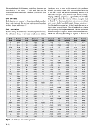
![deep drilling, the drill should be withdrawn at intervals to
relieve chip packing and to ensure the lubricant reaches the
point. As a general rule, if the drill is large or the material
HSS
SS
hard, use a lubricant.
Reamers
Reamers, used for enlarging holes and finishing them smooth Figure 4-49. Drill stop.
to a required size, are made in many styles. They can be
straight or tapered, solid or expansive, and come with straight
or helical flutes. Figure 4-48 illustrates three types of reamers:
1. Three or four fluted production bullet reamers are
customarily used where a finer finish and/or size is
needed than can be achieved with a standard drill bit.
2. Standard or straight reamer.
3. Piloted reamer, with the end reduced to provide
accurate alignment.
Bushing holder Arm-type bushing holder
1
Figure 4-50. Drill bushings.
Drill bushing types:
2
1. Tube—hand-held in an existing hole
2. Commercial—twist lock
3
3. Commercial—threaded
Drill Bushing Holder Types
Figure 4-48. Reamers. There are four types of drill bushing holder:
The cylindrical parts of most straight reamers are not cutting 1. Standard—fine for drilling flat stock or tubing/rod;
edges, but merely grooves cut for the full length of the reamer uses insert-type bushings.
body. These grooves provide a way for chips to escape and 2. Egg cup—improvement on standard tripod base;
a channel for lubricant to reach the cutting edge. Actual allows drilling on both flat and curved material;
cutting is done on the end of the reamer. The cutting edges interchangeable bushings allows flexibility.
are normally ground to a bevel of 45° ± 5°. [Figure 4-51]
Reamer flutes are not designed to remove chips like a drill. 3. Plate—used primarily for interchangeable production
Do not attempt to withdraw a reamer by turning it in the components; uses commercial bushings and self-
reverse direction because chips can be forced into the surface, feeding drills.
scarring the hole.
Drill Stops
A spring drill stop is a wise investment. [Figure 4-49]
Properly adjusted, it can prevent excessive drill penetration
that might damage underlying structure or injure personnel
and prevent the drill chuck from marring the surface. Drill
stops can be made from tubing, fiber rod, or hard rubber.
Drill Bushings and Guides
There are several types of tools available that aid in holding
the drill perpendicular to the part. They consist of a hardened
bushing anchored in a holder. [Figure 4-50] Figure 4-51. Bushing holder.
4-19](https://image.slidesharecdn.com/faa-h-8083-31-amt-airframe-vol-1-130226145854-phpapp01/85/Faa-h-8083-31-amt-airframe-vol-1-187-320.jpg)
![4. Arm—used when drilling critical structure; a pilot drill bit that is too large because it would
can be locked in position; uses interchangeable cause the corners and cutting lips of the final drill bit
commercial bushings. to be dulled, burned, or chipped. It also contributes
to chattering and drill motor stalling. Pilot drill at
Hole Drilling Techniques each mark.
Precise location of drilled holes is sometimes required. 6. Place the drill point at the center of the crossed lines,
When locating holes to close tolerances, accurately located perpendicular to the surface, and, with light pressure,
punch marks need to be made. If a punch mark is too small, start drilling slowly. Stop drilling after a few turns and
the chisel edge of the drill bit may bridge it and “walk off” check to see if the drill bit is starting on the mark. It
the exact location before starting. If the punch mark is too should be; if not, it is necessary to walk the hole a little
heavy, it may deform the metal and/or result in a local strain by pointing the drill in the direction it should go, and
hardening where the drill bit is to start cutting. The best size rotating it carefully and intermittently until properly
for a punch mark is about the width of the chisel edge of the lined up.
drill bit to be used. This holds the drill point in place while
starting. The procedure that ensures accurate holes follows: 7. Enlarge each pilot drilled hole to final size.
[Figure 4-52]
Drilling Large Holes
The following technique can be used to drill larger holes.
Special tooling has been developed to drill large holes to
precise tolerances. [Figure 4-53]
Figure 4-52. Drilled sheet metal.
Figure 4-53. Drilling large holes.
1. Measure and lay out the drill locations carefully and
mark with crossed lines.
1. Pilot drill using a drill bushing. Bushings are sized for
NOTE: The chisel edge is the least efficient operating 1
⁄8, 3⁄16, or 1⁄4 drill bits.
surface element of the twist drill bit because it does
not cut, but actually squeezes or extrudes the work 2. Step drill bits are used to step the hole to approximately
material. 1
⁄64-inch smaller than the final hole size. The aligning
step diameter matches the pilot drill bit size.
2. Use a sharp prick punch or spring-loaded center punch
and magnifying glass to further mark the holes. 3. Finish ream to size using a step reamer. The aligning
step diameter matches the core drill bit size. Reamers
3. Seat a properly ground center punch (120°–135°) in
should be available for both clearance and interference
the prick punch mark and, holding the center punch
fit hole sizes.
perpendicular to the surface, strike a firm square blow
with a hammer. NOTE: Holes can also be enlarged by using a series
of step reamers.
4. Mark each hole with a small drill bit ( 1⁄16-inch
recommended) to check and adjust the location prior
Chip Chasers
to pilot drilling.
The chip chaser is designed to remove chips and burrs lodged
5. For holes 3⁄ 16-inch and larger, pilot drilling is between sheets of metal after drilling holes for riveting.
recommended. Select a drill bit equal to the width of [Figure 4-54] Chip chasers have a plastic molded handle
the chisel edge of the final drill bit size. Avoid using and a flexible steel blade with a hook in the end.
4-20](https://image.slidesharecdn.com/faa-h-8083-31-amt-airframe-vol-1-130226145854-phpapp01/85/Faa-h-8083-31-amt-airframe-vol-1-188-320.jpg)
![slightly when the deforming force is removed. If the material
shows signs of cracking during cold forming over small radii,
the material should be formed in the annealed condition.
Annealing, the process of toughening steel by gradually
heating and cooling it, removes the temper from metal,
making it softer and easier to form. Parts containing small
radii or compound curvatures must be formed in the annealed
condition. After forming, the part is heat treated to a tempered
condition before use on the aircraft.
Construction of interchangeable structural and nonstructural
parts is achieved by forming flat sheet stock to make channel,
angle, zee, and hat section members. Before a sheet metal part
Figure 4-54. Chip chaser. is formed, a flat pattern is made to show how much material
is required in the bend areas, at what point the sheet must be
Forming Tools
inserted into the forming tool, or where bend lines are located.
Sheet metal forming dates back to the days of the blacksmith Determination of bend lines and bend allowances is discussed
who used a hammer and hot oven to mold metal into the in greater detail in the section on layout and forming.
desired form. Today’s aircraft technician relies on a wide
variety of powered and hand-operated tools to precisely bend Bar Folding Machine
and fold sheet metal to achieve the perfect shape. Forming The bar folder is designed for use in making bends or folds
tools include straight line machines, such as the bar folder and along edges of sheets. [Figure 4-56] This machine is best
press brake, as well as rotary machines, such as the slip roll suited for folding small hems, flanges, seams, and edges to
former. Forming sheet metal requires a variety of tools and be wired. Most bar folders have a capacity for metal up to 22
equipment (both powered and manual), such as the piccolo gauge in thickness and 42 inches in length. Before using the
former, shrinking and stretching tools, form blocks, and bar folder, several adjustments must be made for thickness of
specialized hammers and mallets. [Figure 4-55] material, width of fold, sharpness of fold, and angle of fold.
The adjustment for thickness of material is made by adjusting
the screws at each end of the folder. As this adjustment is
made, place a piece of metal of the desired thickness in the
folder and raise the operating handle until the small roller
rests on the cam. Hold the folding blade in this position and
adjust the setscrews until the metal is clamped securely and
evenly the full length of the folding blade. After the folder
has been adjusted, test each end of the machine separately
with a small piece of metal by actually folding it.
Figure 4-55. Hammer and mallet forming.
Tempered sheet stock is used in forming operations whenever
possible in typical repairs. Forming that is performed in the
tempered condition, usually at room temperature, is known
as cold-forming. Cold forming eliminates heat treatment and
the straightening and checking operations required to remove
the warp and twist caused by the heat treating process. Cold-
formed sheet metal experiences a phenomenon known as Figure 4-56. Bar folder.
spring-back, which causes the worked piece to spring back
4-21](https://image.slidesharecdn.com/faa-h-8083-31-amt-airframe-vol-1-130226145854-phpapp01/85/Faa-h-8083-31-amt-airframe-vol-1-189-320.jpg)
![There are two positive stops on the folder, one for 45° folds The bending capacity of a cornice brake is determined by the
or bends and the other for 90° folds or bends. A collar is manufacturer. Standard capacities of this machine are from
provided that can be adjusted to any degree of bend within 12- to 22-gauge sheet metal, and bending lengths are from 3
the capacity of the machine. to 12 feet. The bending capacity of the brake is determined by
the bending edge thickness of the various bending leaf bars.
For forming angles of 45° or 90°, the appropriate stop is
moved into place. This allows the handle to be moved Most metals have a tendency to return to their normal
forward to the correct angle. For forming other angles, the shape—a characteristic known as spring-back. If the cornice
adjustable collar is used. This is accomplished by loosening brake is set for a 90° bend, the metal bent probably forms
the setscrew and setting the stop at the desired angle. After an angle of about 87° to 88°. Therefore, if a bend of 90° is
setting the stop, tighten the setscrew and complete the bend. desired, set the cornice brake to bend an angle of about 93°
To make the fold, adjust the machine correctly and then insert to allow for spring-back.
the metal. The metal goes between the folding blade and the
jaw. Hold the metal firmly against the gauge and pull the Box and Pan Brake (Finger Brake)
operating handle toward the body. As the handle is brought The box and pan brake, often called the finger brake because
forward, the jaw automatically raises and holds the metal until it is equipped with a series of steel fingers of varying widths,
the desired fold is made. When the handle is returned to its lacks the solid upper jaw of the cornice brake. [Figure 4-58]
original position, the jaw and blade return to their original The box and pan brake can be used to do everything that the
positions and release the metal. cornice brake can do, as well as several things the cornice
brake cannot do.
Cornice Brake
A brake is similar to a bar folder because it is also used for
turning or bending the edges of sheet metal. The cornice brake
is more useful than the bar folder because its design allows
the sheet metal to be folded or formed to pass through the
jaws from front to rear without obstruction. [Figure 4-57] In
contrast, the bar folder can form a bend or edge only as wide
as the depth of its jaws. Thus, any bend formed on a bar folder
can also be made on the cornice brake.
Clamping fingers
Figure 4-58. Box and pan brake.
The box and pan brake is used to form boxes, pans, and
other similar shaped objects. If these shapes were formed
on a cornice brake, part of the bend on one side of the box
would have to be straightened in order to make the last bend.
With a finger brake, simply remove the fingers that are in the
way and use only the fingers required to make the bend. The
fingers are secured to the upper leaf by thumbscrews. All the
fingers not removed for an operation must be securely seated
Figure 4-57. Cornice brake. and firmly tightened before the brake is used. The radius of
the nose on the clamping fingers is usually rather small and
In making ordinary bends with the cornice brake, the sheet frequently requires nose radius shims to be custom made for
is placed on the bed with the sight line (mark indicating line the total length of the bend.
of bend) directly under the edge of the clamping bar. The
clamping bar is then brought down to hold the sheet firmly Press Brake
in place. The stop at the right side of the brake is set for the Since most cornice brakes and box and pan brakes are limited
proper angle or amount of bend and the bending leaf is raised to a maximum forming capacity of approximately 0.090
until it strikes the stop. If other bends are to be made, the inch annealed aluminum, 0.063-inch 7075T6, or 0.063-inch
clamping bar is lifted and the sheet is moved to the correct stainless steel, operations that require the forming of thicker
position for bending.
4-22](https://image.slidesharecdn.com/faa-h-8083-31-amt-airframe-vol-1-130226145854-phpapp01/85/Faa-h-8083-31-amt-airframe-vol-1-190-320.jpg)
![and more complex parts use a press brake. [Figure 4-59] Slip Roll Former
The press brake is the most common machine tool used to With the exception of the brake, the slip roll is probably
bend sheet metal and applies force via mechanical and/or used more than any other machine in the shop. [Figure 4-60]
hydraulic components to shape the sheet metal between the This machine is used to form sheets into cylinders or other
punch and die. Narrow U-channels (especially with long legs) straight curved surfaces. It consists of right and left end
and hat channel stringers can be formed on the press brake frames with three solid rolls mounted in between. Gears,
by using special gooseneck or offset dies. Special urethane which are operated by either a hand crank or a power drive,
lower dies are useful for forming channels and stringers. connect the two gripping rolls. These rolls can be adjusted to
Power press brakes can be set up with back stops (some are the thickness of the metal by using the two adjusting screws
computer controlled) for high volume production. Press brake located on the bottom of each frame. The two most common
operations are usually done manually and require skill and of these forming machines are the slip roll former and the
knowledge of safe use. rotary former. Available in various sizes and capabilities,
these machines come in manual or powered versions.
The slip roll former in Figure 4-60 is manually operated and
consists of three rolls, two housings, a base, and a handle.
The handle turns the two front rolls through a system of gears
enclosed in the housing. The front rolls serve as feeding, or
gripping, rolls. The rear roll gives the proper curvature to
the work. When the metal is started into the machine, the
rolls grip the metal and carry it to the rear roll, which curves
it. The desired radius of a bend is obtained by the rear roll.
The bend radius of the part can be checked as the forming
operation progresses by using a circle board or radius gauge.
The gauges can be made by cutting a piece of material to
Figure 4-59. Press brake.
Operating handle
Grooves
Grooves
Housing
Upper front roll
Base
Lower front roll
Figure 4-60. Slip roll former.
4-23](https://image.slidesharecdn.com/faa-h-8083-31-amt-airframe-vol-1-130226145854-phpapp01/85/Faa-h-8083-31-amt-airframe-vol-1-191-320.jpg)
![the required finished radius and comparing it to the radius [Figure 4-62] Various shaped rolls can be installed on the
being formed by the rolling operation. On some material, rotary machine to perform these operations. The rotary
the forming operation must be performed by passing the machine works best with thinner annealed materials.
material through the rolls several times with progressive
settings on the forming roll. On most machines, the top roll Stretch Forming
can be released on one end, permitting the formed sheet to In the process of stretch forming, a sheet of metal is shaped
be removed from the machine without distortion. by stretching it over a formed block to just beyond the elastic
limit where permanent set takes place with a minimum
The front and rear rolls are grooved to permit forming of amount of spring-back. To stretch the metal, the sheet is
objects that have wired edges. The upper roll is equipped with rigidly clamped at two opposite edges in fixed vises. Then, the
a release that permits easy removal of the metal after it has metal is stretched by moving a ram that carries the form block
been formed. When using the slip roll former, the lower front against the sheet with the pressure from the ram causing the
roll must be raised or lowered before inserting the sheet of material to stretch and wrap to the contour of the form block.
metal. If the object has a folded edge, there must be enough
clearance between the rolls to prevent flattening the fold. If Stretch forming is normally restricted to relatively large
a metal requiring special care (such as aluminum) is being parts with large radii of curvature and shallow depth, such as
formed, the rolls must be clean and free of imperfections. contoured skin. Uniform contoured parts produced at a faster
speed give stretch forming an advantage over hand formed
The rear roll must be adjusted to give the proper curvature parts. Also, the condition of the material is more uniform
to the part being formed. There are no gauges that indicate than that obtained by hand forming.
settings for a specific diameter; therefore, trial and error
settings must be used to obtain the desired curvature. The Drop Hammer
metal should be inserted between the rolls from the front of The drop hammer forming process produces shapes by the
the machine. Start the metal between the rolls by rotating the progressive deformation of sheet metal in matched dies under
operating handle in a clockwise direction. A starting edge is the repetitive blows of a gravity-drop hammer or a power-
formed by holding the operating handle firmly with the right drop hammer. The configurations most commonly formed
hand and raising the metal with the left hand. The bend of by the process include shallow, smoothly contoured double-
the starting edge is determined by the diameter of the part curvature parts, shallow-beaded parts, and parts with irregular
being formed. If the edge of the part is to be flat or nearly and comparatively deep recesses. Small quantities of cup-
flat, a starting edge should not be formed. shaped and box-shaped parts, curved sections, and contoured
flanged parts are also formed. Drop hammer forming is not a
Ensure that fingers and loose clothing are clear of the rolls precision forming method and cannot provide tolerances as
before the actual forming operation is started. Rotate the close as 0.03-inch to 0.06-inch. Nevertheless, the process is
operating handle until the metal is partially through the rolls often used for sheet metal parts, such as aircraft components,
and change the left hand from the front edge of the sheet to the that undergo frequent design changes, or for which there is
upper edge of the sheet. Then, roll the remainder of the sheet a short run expectancy.
through the machine. If the desired curvature is not obtained,
return the metal to its starting position by rotating the handle Hydropress Forming
counterclockwise. Raise or lower the rear roll and roll the The rubber pad hydropress can be utilized to form many
metal through the rolls again. Repeat this procedure until varieties of parts from aluminum and its alloys with relative
the desired curvature is obtained, then release the upper roll ease. Phenolic, masonite, kirksite, and some types of hard
and remove the metal. If the part to be formed has a tapered setting moulding plastic have been used successfully as form
shape, the rear roll should be set so that the rolls are closer blocks to press sheet metal parts, such as ribs, spars, fans,
together on one end than on the opposite end. The amount etc. To perform a press forming operation:
of adjustment must be determined by experimentation. If the
1. Cut a sheet metal blank to size and deburr edges.
job being formed has a wired edge, the distance between the
upper and lower rolls and the distance between the lower front 2. Set the form block (normally male) on the lower
roll and the rear roll should be slightly greater at the wired press platen.
end than at the opposite end. [Figure 4-61] 3. Place the prepared sheet metal blank (with locating
pins to prevent shifting of the blank when the pressure
Rotary Machine is applied).
The rotary machine is used on cylindrical and flat sheet
4. Lower or close the rubber pad-filled press head over
metal to shape the edge or to form a bead along the edge.
the form block and the rubber envelope.
4-24](https://image.slidesharecdn.com/faa-h-8083-31-amt-airframe-vol-1-130226145854-phpapp01/85/Faa-h-8083-31-amt-airframe-vol-1-192-320.jpg)
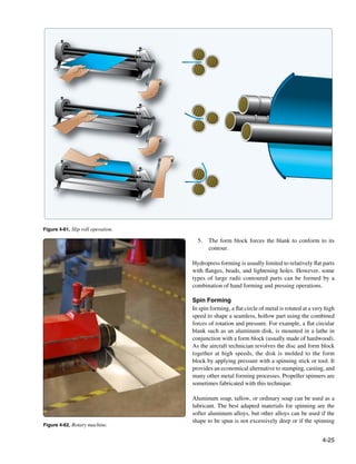
![is done in stages utilizing intermediate annealing to remove To use the English wheel, place a piece of sheet metal
the effect of strain hardening that results from the spinning between the wheels (one above and one below the metal).
operation. Hot forming is used in some instances when Then, roll the wheels against one another under a pre-adjusted
spinning thicker and harder alloys. [Figure 4-63] pressure setting. Steel or aluminum can be shaped by pushing
the metal back and forth between the wheels. Very little
pressure is needed to shape the panel, which is stretched or
raised to the desired shape. It is important to work slowly and
gradually curve the metal into the desired shape. Monitor the
curvature with frequent references to the template.
The English wheel is used for shaping low crowns on large
panels and polishing or planishing (to smooth the surface of a
metal by rolling or hammering it) parts that have been formed
with power hammers or hammer and shot bag.
Piccolo Former
The piccolo former is used for cold forming and rolling
sheet metal and other profile sections (extrusions).
Figure 4-63. Spin forming. [Figure 4-65] The position of the ram is adjustable in
height by means of either a handwheel or a foot pedal that
Forming With an English Wheel permits control of the working pressure. Be sure to utilize
The English wheel, a popular type of metal forming tool the adjusting ring situated in the machine head to control the
used to create double curves in metal, has two steel wheels maximum working pressure. The forming tools are located in
between which metal is formed. [Figure 4-64] Keep in mind the moving ram and the lower tool holder. Depending on the
that the English wheel is primarily a stretching machine, so variety of forming tools included, the operator can perform
it stretches and thins the metal before forming it into the such procedures as forming edges, bending profiles, removing
desired shape. Thus, the operator must be careful not to wrinkles, spot shrinking to remove buckles and dents, or
over-stretch the metal. expanding dome sheet metal. Available in either fiberglass
(to prevent marring the surface) or steel (for working harder
materials) faces, the tools are the quick-change type.
Figure 4-65. Piccolo former.
Shrinking and Stretching Tools
Shrinking Tools
Shrinking dies repeatedly clamp down on the metal, then shift
inward. [Figure 4-66] This compresses the material between
the dies, which actually slightly increases the thickness of
the metal. Strain hardening takes place during this process,
so it is best to set the working pressure high enough to
complete the shape rather quickly (eight passes could be
Figure 4-64. English wheel. considered excessive).
4-26](https://image.slidesharecdn.com/faa-h-8083-31-amt-airframe-vol-1-130226145854-phpapp01/85/Faa-h-8083-31-amt-airframe-vol-1-194-320.jpg)
![Hand-Operated Shrinker and Stretcher
The hand-operated shrinker and structure is similar to the
manual foot-operated unit, except a handle is used to apply
force to shrinking and stretching blocks. The dies are all
metal and leave marks on aluminum that need to be blended
out after the shrinking or stretching operation. [Figure 4-67]
Figure 4-66. Shrinking and stretching tools.
CAUTION: Avoid striking a die on the radius itself when
forming a curved flange. This damages the metal in the radius
and decreases the angle of bend.
Stretching Tools
Stretching dies repeatedly clamp down on the surface and
then shift outward. This stretches the metal between the dies, Figure 4-67. Hand-operated shrinker and stretcher unit.
which decreases the thickness in the stretched area. Striking
the same point too many times weakens and eventually cracks Dollies and Stakes
the part. It is advantageous to deburr or even polish the edges Sheet metal is often formed or finished (planished) over
of a flange that must undergo even moderate stretching to anvils, available in a variety of shapes and sizes, called
avoid crack formation. Forming flanges with existing holes dollies and stakes. These are used for forming small, odd-
causes the holes to distort and possibly crack or substantially shaped parts, or for putting on finishing touches for which
weaken the flange. a large machine may not be suited. Dollies are meant to be
held in the hand, whereas stakes are designed to be supported
Manual Foot-Operated Sheet Metal Shrinker by a flat cast iron bench plate fastened to the workbench.
[Figure 4-68]
The manual foot-operated sheet metal shrinker operates very
similarly to the Piccolo former though it only has two primary
Most stakes have machined, polished surfaces that have been
functions: shrinking and stretching. The only dies available
hardened. Use of stakes to back up material when chiseling,
are steel faced and therefore tend to mar the surface of the
or when using any similar cutting tool, defaces the surface
metal. When used on aluminum, it is necessary to gently
of the stake and makes it useless for finish work.
blend out the surface irregularities (primarily in the cladding),
then treat and paint the part.
Hardwood Form Blocks
Since this is a manual machine, it relies on leg power, as the Hardwood form blocks can be constructed to duplicate
operator repeatedly steps on the foot pedal. The more force practically any aircraft structural or nonstructural part. The
is applied, the more stresses are concentrated at that single wooden block or form is shaped to the exact dimensions and
point. It yields a better part with a series of smaller stretches contour of the part to be formed.
(or shrinks) than with a few intense ones. Squeezing the dies
over the radius damages the metal and flattens out some of V-Blocks
the bend. It may be useful to tape a thick piece of plastic or V-blocks made of hardwood are widely used in airframe
micarta to the opposite leg to shim the radius of the angle metalwork for shrinking and stretching metal, particularly
away from the clamping area of the dies. angles and flanges. The size of the block depends on the work
being done and on personal preference. Although any type
NOTE: Watch the part change shape while slowly applying of hardwood is suitable, maple and ash are recommended for
pressure. A number of small stretches works more effectively best results when working with aluminum alloys.
than one large one. If applying too much pressure, the metal
has the tendency to buckle.
4-27](https://image.slidesharecdn.com/faa-h-8083-31-amt-airframe-vol-1-130226145854-phpapp01/85/Faa-h-8083-31-amt-airframe-vol-1-195-320.jpg)
![through the pores of the canvas. Bags can also be filled with
shot as an alternative to sand.
Sheet Metal Hammers and Mallets
The sheet metal hammer and the mallet are metal fabrication
hand tools used for bending and forming sheet metal without
marring or indenting the metal. The hammer head is usually
made of high carbon, heat-treated steel, while the head of the
mallet, which is usually larger than that of the hammer, is
made of rubber, plastic, wood, or leather. In combination with
a sandbag, V-blocks, and dies, sheet metal body hammers
and mallets are used to form annealed metal. [Figure 4-69]
Figure 4-68. Dollies and stakes.
Shrinking Blocks
Figure 4-69. Sheet metal mallet and hammers.
A shrinking block consists of two metal blocks and some
device for clamping them together. One block forms the
base and the other is cut away to provide space where the Sheet Metal Holding Devices
crimped material can be hammered. The legs of the upper In order to work with sheet metal during the fabrication
jaw clamp the material to the base block on each side of process, the aviation technician uses a variety of holding
the crimp to prevent the material from creeping away, but devices, such as clamps, vises, and fasteners to hold the
remains stationary while the crimp is hammered flat (being work together. The type of operation being performed and
shrunk). This type of crimping block is designed to be held the type of metal being used determine what type of the
in a bench vise. holding device is needed.
Shrinking blocks can be made to fit any specific need. The Clamps and Vises
basic form and principle remain the same, even though the Clamps and vises hold materials in place when it is not
blocks may vary considerably in size and shape. possible to handle a tool and the workpiece at the same
time. A clamp is a fastening device with movable jaws that
Sandbags has opposing, often adjustable, sides or parts. An essential
A sandbag is generally used as a support during the bumping fastening device, it holds objects tightly together to prevent
process. A serviceable bag can be made by sewing heavy movement or separation. Clamps can be either temporary
canvas or soft leather to form a bag of the desired size, and or permanent. Temporary clamps, such as the carriage
filling it with sand which has been sifted through a fine clamp (commonly called the C-clamp), are used to position
mesh screen. components while fixing them together.
Before filling canvas bags with sand, use a brush to coat the C-Clamps
inside of the bag with softened paraffin or beeswax, which The C-clamp is shaped like a large C and has three main
forms a sealing layer and prevents the sand from working parts: threaded screw, jaw, and swivel head. [Figure 4-70]
4-28](https://image.slidesharecdn.com/faa-h-8083-31-amt-airframe-vol-1-130226145854-phpapp01/85/Faa-h-8083-31-amt-airframe-vol-1-196-320.jpg)
![Figure 4-70. C-clamps. Figure 4-71. A utility vise with swivel base and anvil.
The swivel plate or flat end of the screw prevents the end from
turning directly against the material being clamped. C-clamp
size is measured by the dimension of the largest object the
frame can accommodate with the screw fully extended.
The distance from the center line of the screw to the inside
edge of the frame or the depth of throat is also an important
consideration when using this clamp. C-clamps vary in size
from two inches upward. Since C-clamps can leave marks
on aluminum, protect the aircraft covering with masking tape
at the places where the C-clamp is used.
Vises
Vises are another clamping device that hold the workpiece
in place and allow work to be done on it with tools such as
saws and drills. The vise consists of two fixed or adjustable
jaws that are opened or closed by a screw or a lever. The size
of a vise is measured by both the jaw width and the capacity
of the vise when the jaws are fully open. Vises also depend
on a screw to apply pressure, but their textured jaws enhance
gripping ability beyond that of a clamp.
Two of the most commonly used vises are the machinist’s
vise and the utility vise. [Figure 4-71] The machinist’s
vise has flat jaws and usually a swivel base, whereas the Figure 4-72. Cleco and Cleco plier.
utility bench vise has scored, removable jaws and an anvil-
faced back jaw. This vise holds heavier material than the Cleco Fasteners
machinist’s vise and also grips pipe or rod firmly. The back The Cleco fastener consists of a steel cylinder body with a
jaw can be used as an anvil if the work being done is light. plunger on the top, a spring, a pair of step-cut locks, and a
To avoid marring metal in the vise jaws, add some type of spreader bar. These fasteners come in six different sizes: 3⁄32,
padding, such as a ready-made rubber jaw pad. 1
⁄8, 5⁄32, 3⁄16, 1⁄4, and 3⁄8-inch in diameter with the size stamped on
the fastener. Color coding allows for easy size recognition. A
Reusable Sheet Metal Fasteners special type of plier fits the six different sizes. When installed
Reusable sheet metal fasteners temporarily hold drilled sheet correctly, the reusable Cleco fastener keeps the holes in the
metal parts accurately in position for riveting or drilling. If separate sheets aligned.
sheet metal parts are not held tightly together, they separate
while being riveted or drilled. The Cleco (also spelled Cleko)
fastener is the most commonly used sheet metal holder.
[Figure 4-72]
4-29](https://image.slidesharecdn.com/faa-h-8083-31-amt-airframe-vol-1-130226145854-phpapp01/85/Faa-h-8083-31-amt-airframe-vol-1-197-320.jpg)
![Hex Nut and Wing Nut Temporary Sheet Fasteners rows approximately five inches apart. Tubes, bars, rods,
Hex nut and wing nut fasteners are used to temporarily fasten and extruded shapes are marked with specification numbers
sheets of metal when higher clamp up pressure is required. or code markings at intervals of three to five feet along the
[Figure 4-73] Hex nut fasteners provide up to 300 pounds length of each piece.
of clamping force with the advantage of quick installation
and removal with a hex nut runner. Wing nut sheet metal The commercial code marking consists of a number
fasteners, characterized by wing shaped protrusions, not only that identifies the particular composition of the alloy.
provide a consistent clamping force from 0 to 300 pounds, but Additionally, letter suffixes designate the basic temper
the aircraft technician can turn and tighten these fasteners by designations and subdivisions of aluminum alloys.
hand. Cleco hex nut fasteners are identical to Cleco wing nut
fasteners, but the Cleco hex nut can be used with pneumatic The aluminum and various aluminum alloys used in aircraft
Cleco installers. repair and construction are as follows:
• Aluminum designated by the symbol 1100 is used
where strength is not an important factor, but where
weight economy and corrosion resistance are desired.
This aluminum is used for fuel tanks, cowlings, and oil
tanks. It is also used for repairing wingtips and tanks.
This material is weldable.
• Alloy 3003 is similar to 1100 and is generally used
for the same purposes. It contains a small percentage
of magnesium and is stronger and harder than
1100 aluminum.
• Alloy 2014 is used for heavy-duty forgings, plates,
extrusions for aircraft fittings, wheels, and major
Figure 4-73. Hex nut fastener. structural components. This alloy is often used for
applications requiring high strength and hardness, as
Aluminum Alloys
well as for service at elevated temperatures.
Aluminum alloys are the most frequently encountered type
• Alloy 2017 is used for rivets. This material is now in
of sheet metal in aircraft repair. AC 43.13.1 Chapter 4, Metal
limited use.
Structure, Welding, and Brazing: Identification of Metals
(as revised) provides an in-depth discussion of all metal • Alloy 2024, with or without Alclad™ coating, is
types. This section describes the aluminum alloys used in the used for aircraft structures, rivets, hardware, machine
forming processes discussed in the remainder of the chapter. screw products, and other miscellaneous structural
applications. In addition, this alloy is commonly
In its pure state, aluminum is lightweight, lustrous, and used for heat-treated parts, airfoil and fuselage skins,
corrosion resistant. The thermal conductivity of aluminum extrusions, and fittings.
is very high. It is ductile, malleable, and nonmagnetic. When • Alloy 2025 is used extensively for propeller blades.
combined with various percentages of other metals (generally
copper, manganese, and magnesium), aluminum alloys that • Alloy 2219 is used for fuel tanks, aircraft skin, and
are used in aircraft construction are formed. Aluminum structural components. This material has high fracture
alloys are lightweight and strong. They do not possess the toughness and is readily weldable. Alloy 2219 is also
corrosion resistance of pure aluminum and are usually treated highly resistant to stress corrosion cracking.
to prevent deterioration. Alclad™ aluminum is an aluminum • Alloy 5052 is used where good workability, very
alloy with a protective cladding of aluminum to improve its good corrosion resistance, high fatigue strength,
corrosion resistance. weldability, and moderate static strength are desired.
This alloy is used for fuel, hydraulic, and oil lines.
To provide a visual means for identifying the various • Alloy 5056 is used for making rivets and cable
grades of aluminum and aluminum alloys, aluminum stock sheeting and in applications where aluminum comes
is usually marked with symbols such as a Government into contact with magnesium alloys. Alloy 5056
Specification Number, the temper or condition furnished, is generally resistant to the most common forms
or the commercial code marking. Plate and sheet are usually of corrosion.
marked with specification numbers or code markings in
4-30](https://image.slidesharecdn.com/faa-h-8083-31-amt-airframe-vol-1-130226145854-phpapp01/85/Faa-h-8083-31-amt-airframe-vol-1-198-320.jpg)
![• Cast aluminum alloys are used for cylinder Description
heads, crankcases, fuel injectors, carburetors, and Before installation, the rivet consists of a smooth cylindrical
landing wheels. shaft with a factory head on one end. The opposite end is
• Various alloys, including 3003, 5052, and 1100 called the bucktail. To secure two or more pieces of sheet
aluminum, are hardened by cold working rather than metal together, the rivet is placed into a hole cut just a bit
by heat treatment. Other alloys, including 2017 and larger in diameter than the rivet itself. Once placed in this
2024, are hardened by heat treatment, cold working, predrilled hole, the bucktail is upset or deformed by any of
or a combination of the two. Various casting alloys several methods from hand-held hammers to pneumatically
are hardened by heat treatment. driven squeezing tools. This action causes the rivet to expand
about 11⁄2 times the original shaft diameter, forming a second
• Alloy 6061 is generally weldable by all commercial
head that firmly holds the material in place.
procedures and methods. It also maintains acceptable
toughness in many cryogenic applications. Alloy 6061
Rivet Head Shape
is easily extruded and is commonly used for hydraulic
and pneumatic tubing. Solid rivets are available in several head shapes, but the
universal and the 100° countersunk head are the most
• Although higher in strength than 2024, alloy 7075 commonly used in aircraft structures. Universal head rivets
has a lower fracture toughness and is generally used were developed specifically for the aircraft industry and
in tension applications where fatigue is not critical. designed as a replacement for both the round and brazier head
The T6 temper of 7075 should be avoided in corrosive rivets. These rivets replaced all protruding head rivets and are
environments. However, the T7351 temper of 7075 used primarily where the protruding head has no aerodynamic
has excellent stress corrosion resistance and better significant. They have a flat area on the head, a head diameter
fracture toughness than the T6 temper. The T76 temper twice the shank diameter, and a head height approximately
is often used to improve the resistance of 7075 to 42.5 percent of the shank diameter. [Figure 4-74]
exfoliate corrosion.
Structural Fasteners
Structural fasteners, used to join sheet metal structures
securely, come in thousands of shapes and sizes with many
of them specialized and specific to certain aircraft. Since
some structural fasteners are common to all aircraft, this
section focuses on the more frequently used fasteners. For
the purposes of this discussion, fasteners are divided into two Countersunk head Universal head
main groups: solid shank rivets and special purpose fasteners
that include blind rivets.
Figure 4-74. Solid shank rivet styles.
Solid Shank Rivet
The solid shank rivet is the most common type of rivet used
in aircraft construction. Used to join aircraft structures, solid The countersunk head angle can vary from 60° to 120°, but
shank rivets are one of the oldest and most reliable types of the 100° has been adopted as standard because this head style
fastener. Widely used in the aircraft manufacturing industry, provides the best possible compromise between tension/
solid shank rivets are relatively low-cost, permanently shear strength and flushness requirements. This rivet is used
installed fasteners. They are faster to install than bolts where flushness is required because the rivet is flat-topped
and nuts since they adapt well to automatic, high-speed and undercut to allow the head to fit into a countersunk or
installation tools. Rivets should not be used in thick materials dimpled hole. The countersunk rivet is primarily intended
or in tensile applications, as their tensile strengths are quite for use when aerodynamics smoothness is critical, such as
low relative to their shear strength. The longer the total grip on the external surface of a high-speed aircraft.
length (the total thickness of sheets being joined), the more
difficult it becomes to lock the rivet. Typically, rivets are fabricated from aluminum alloys, such
as 2017-T4, 2024-T4, 2117-T4, 7050, and 5056. Titanium,
Riveted joints are neither airtight nor watertight unless special nickel-based alloys, such as Monel® (corrosion-resistant
seals or coatings are used. Since rivets are permanently steel), mild steel or iron, and copper rivets are also used for
installed, they must be removed by drilling them out, a rivets in certain cases.
laborious task.
4-31](https://image.slidesharecdn.com/faa-h-8083-31-amt-airframe-vol-1-130226145854-phpapp01/85/Faa-h-8083-31-amt-airframe-vol-1-199-320.jpg)
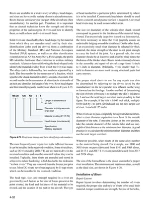
![Driven Rivet Standards Standard Rivet Alloy Code Markings
A, AD, B, DD Rivets Alloy code—A Alloy code—B
Alloy—1100 or 3003 aluminum Alloy—5056 aluminum
Predrive Head marking—None Head marking—raised cross
protrusion
1.33 d 1.5 d
Formed
head .66 d .5 d .33 d
dimension 1.25 d 1.5 d 1.66 d
Minimum Preferred Maximum
Shear strength—10 KSI Shear strength—28 KSI
N
Nonstructural uses only
t t l l
D, E, (KE), M Rivets
Predrive Alloy code—AD Alloy code—D
protrusion Alloy—2117 aluminum Alloy—2017 aluminum
1.25 d 1.33 d
Head marking—Dimple Head marking—Raised dot
Formed
head .66 d .6 d .5 d
dimension 1.25 d 1.4 d 1.5 d
Minimum Preferred Maximum
Figure 4-76. Rivet formed head dimensions.
Shear strength—30 KSI Shear strength—38 KSI
38 KSI When driven as received
the distances between the holes, and the distance between the 34 KSI When re-heat treated
holes and the edges of the patch. Distances are measured in
terms of rivet diameter. Alloy code—DD Alloy code—E, [KE*] *Boeing code
Alloy—2024 aluminum Alloy—2017 aluminum
(raised
Head marking—Two bars (raised) Head marking—Raised ring
Rivet Length
To determine the total length of a rivet to be installed, the
combined thickness of the materials to be joined must first
be known. This measurement is known as the grip length.
The total length of the rivet equals the grip length plus the
amount of rivet shank needed to form a proper shop head.
The latter equals one and a half times the diameter of the rivet
shank. Where A is total rivet length, B is grip length, and Shear strength—41 KSI Shear strength—43 KSI
C is the length of the material needed to form a shop head, Must be driven in “W” condition Replacement for DD rivet
(Ice-Box) to be driven in “T” condition
this formula can be represented as A = B + C. [Figure 4-76]
Alloy code—E
Alloy—7050 aluminum
Rivet Strength
circl
cle
Head marking—raised circle
For structural applications, the strength of the replacement
rivets is of primary importance. [Figure 4-77] Rivets made
of material that is lower in strength should not be used as
replacements unless the shortfall is made up by using a larger
rivet. For example, a rivet of 2024-T4 aluminum alloy should
not be replaced with one of 2117-T4 or 2017-T4 aluminum
alloy unless the next larger size is used.
Shear strength—54 KSI
The 2117-T rivet is used for general repair work, since it
requires no heat treatment, is fairly soft and strong, and is
highly corrosion resistant when used with most types of
Figure 4-77. Rivet allow strength.
alloys. Always consult the maintenance manual for correct
4-33](https://image.slidesharecdn.com/faa-h-8083-31-amt-airframe-vol-1-130226145854-phpapp01/85/Faa-h-8083-31-amt-airframe-vol-1-201-320.jpg)
![rivet type and material. The type of rivet head to select for between rivets or pitch should be at least 3 times the
a particular repair job can be determined by referring to the diameter; and the distance between rivet rows should
type used within the surrounding area by the manufacturer. never be less than 21⁄2 times the diameter.
A general rule to follow on a flush-riveted aircraft is to apply
flush rivets on the upper surface of the wing and stabilizers, on Figure 4-78 illustrates acceptable ways of laying out a rivet
the lower leading edge back to the spar, and on the fuselage pattern for a repair.
back to the high point of the wing. Use universal head rivets
in all other surface areas. Whenever possible, select rivets of
the same alloy number as the material being riveted.
Stresses Applied to Rivets
Shear is one of the two stresses applied to rivets. The shear
strength is the amount of force required to cut a rivet that
holds two or more sheets of material together. If the rivet
Rivet Spacing Rivet Spacing Rivet Spacing
holds two parts, it is under single shear; if it holds three 6D Distance Between 6D Distance Between 4D Distance Between
sheets or parts, it is under double shear. To determine the Rows 6D Rows 3D Rows 4D
shear strength, the diameter of the rivet to be used must be
found by multiplying the thickness of the skin material by 3. Figure 4-78. Acceptable rivet patterns.
For example, a material thickness of 0.040 inch multiplied by
3 equals 0.120 inch. In this case, the rivet diameter selected Edge Distance
would be 1⁄8 (0.125) inch. Edge distance, also called edge margin by some manufacturers,
is the distance from the center of the first rivet to the edge
Tension is the other stress applied to rivets. The resistance to of the sheet. It should not be less than 2 or more than 4 rivet
tension is called bearing strength and is the amount of tension diameters and the recommended edge distance is about 21⁄2
required to pull a rivet through the edge of two sheets riveted rivet diameters. The minimum edge distance for universal
together or to elongate the hole. rivets is 2 times the diameter of the rivet; the minimum edge
distance for countersunk rivets is 21⁄2 times the diameter of the
Rivet Spacing rivet. If rivets are placed too close to the edge of the sheet,
Rivet spacing is measured between the centerlines of rivets the sheet may crack or pull away from the rivets. If they are
in the same row. The minimum spacing between protruding spaced too far from the edge, the sheet is likely to turn up at
head rivets shall not be less than 31⁄2 times the rivet diameter. the edges. [Figure 4-79]
The minimum spacing between flush head rivets shall not be
less than 4 times the diameter of the rivet. These dimensions E E
Section A-A
AA
may be used as the minimum spacing except when specified
differently in a specific repair procedure or when replacing
existing rivets. D D
On most repairs, the general practice is to use the same rivet
Incorrect - too close to edge Correct E = 2D
spacing and edge distance (distance from the center of the
E = 1½D
hole to the edge of the material) that the manufacturer used in
the area surrounding the damage. The SRM for the particular
A A
aircraft may also be consulted. Aside from this fundamental
rule, there is no specific set of rules that governs spacing
of rivets in all cases. However, there are certain minimum
requirements that must be observed. Resultant crack Safe
• When possible, rivet edge distance, rivet spacing, and
distance between rows should be the same as that of Edge Distance/Edge Minimum Edge Preferred Edge
Margin Distance Distance
the original installation.
Protruding head rivets 2D 2 D + 1/16˝
• When new sections are to be added, the edge distance
Countersunk rivets 2½ D 2½ D + 1/16˝
measured from the center of the rivet should never be
less than 2 times the diameter of the shank; the distance
Figure 4-79. Minimum edge distance.
4-34](https://image.slidesharecdn.com/faa-h-8083-31-amt-airframe-vol-1-130226145854-phpapp01/85/Faa-h-8083-31-amt-airframe-vol-1-202-320.jpg)
![It is good practice to lay out the rivets a little further from the find the edge distance at each end of the row and then lay
edge so that the rivet holes can be oversized without violating off the rivet pitch (distance between rivets), as shown in
the edge distance minimums. Add 1⁄16-inch to the minimum Figure 4-81. In a two-row layout, lay off the first row, place
edge distance or determine the edge distance using the next the second row a distance equal to the transverse pitch from
size of rivet diameter. the first row, and then lay off rivet spots in the second row
so that they fall midway between those in the first row. In
Two methods for obtaining edge distance: the three-row layout, first lay off the first and third rows, then
• The rivet diameter of a protruding head rivet is 3⁄32- use a straightedge to determine the second row rivet spots.
inch. Multiply 2 times 3⁄32-inch to obtain the minimum
edge distance, 3⁄16-inch, add 1⁄16-inch to yield the When splicing a damaged tube, and the rivets pass completely
preferred edge distance of 1⁄4-inch. through the tube, space the rivets four to seven rivet diameters
apart if adjacent rivets are at right angles to each other, and
• The rivet diameter of a protruding head rivet is 3⁄32-inch. space them five to seven rivet diameters apart if the rivets
Select the next size of rivet, which is 1⁄8-inch. Calculate are parallel to each other. The first rivet on each side of the
the edge distance by multiplying 2 times 1⁄8-inch to get joint should be no less than 21⁄2 rivet diameters from the end
1
⁄4-inch. of the sleeve.
Rivet Pitch
Rivet pitch Edge distance
Rivet pitch is the distance between the centers of neighboring (6 to 8 diameters) (2 to 21/2 diameters)
rivets in the same row. The smallest allowable rivet pitch is 3
rivet diameters. The average rivet pitch usually ranges from
4 to 6 rivet diameters, although in some instances rivet pitch
could be as large as 10 rivet diameters. Rivet spacing on parts
that are subjected to bending moments is often closer to the
minimum spacing to prevent buckling of the skin between
the rivets. The minimum pitch also depends on the number of Single-row layout
rows of rivets. One-and three-row layouts have a minimum
pitch of 3 rivet diameters, a two-row layout has a minimum Transverse pitch (75 percent of rivet pitch)
pitch of 4 rivet diameters. The pitch for countersunk rivets
is larger than for universal head rivets. If the rivet spacing
is made at least 1⁄16-inch larger than the minimum, the rivet
hole can be oversized without violating the minimum rivet
spacing requirement. [Figure 4-80]
Two-row layout
Transverse Pitch
Transverse pitch is the perpendicular distance between rivet
rows. It is usually 75 percent of the rivet pitch. The smallest
allowable transverse pitch is 21⁄2 rivet diameters. The smallest
allowable transverse pitch is 21⁄2 rivet diameters. Rivet pitch
and transverse pitch often have the same dimension and are
simply called rivet spacing.
Three-row layout
Rivet Layout Example
The general rules for rivet spacing, as it is applied to a
straight-row layout, are quite simple. In a one-row layout, Figure 4-81. Rivet layout.
Rivet Spacing Minimum Spacing Preferred Spacing
1 and 3 rows protruding head rivet layout 3D 3D + 1/16"
2 row protruding head rivet layout 4D 4D + 1/16"
1 and 3 rows countersunk head rivet layout 3/1/2D 3/1/2D + 1/16"
2 row countersunk head rivet layout 4/1/2D 4/1/2D + 1/16"
Figure 4-80. Rivet spacing.
4-35](https://image.slidesharecdn.com/faa-h-8083-31-amt-airframe-vol-1-130226145854-phpapp01/85/Faa-h-8083-31-amt-airframe-vol-1-203-320.jpg)
![Rivet Installation Tools Bucking faces must be hard enough to resist indentation and
The various tools needed in the normal course of driving remain smooth, but not hard enough to shatter. Sometimes,
and upsetting rivets include drills, reamers, rivet cutters or the more complicated bars must be forged or built up by
nippers, bucking bars, riveting hammers, draw sets, dimpling welding. The bar usually has a concave face to conform to the
dies or other types of countersinking equipment, rivet guns, shape of the shop head to be made. When selecting a bucking
and squeeze riveters. C-clamps, vises, and other fasteners bar, the first consideration is shape. [Figure 4-83] If the bar
used to hold sheets together when riveting were discussed does not have the correct shape, it deforms the rivet head;
earlier in the chapter. Other tools and equipment needed in the if the bar is too light, it does not give the necessary bucking
installation of rivets are discussed in the following paragraphs. weight, and the material may become bulged toward the shop
head. If the bar is too heavy, its weight and the bucking force
Hand Tools may cause the material to bulge away from the shop head.
A variety of hand tools are used in the normal course of
driving and upsetting rivets. They include rivet cutters,
bucking bars, hand riveters, countersinks, and dimpling tools.
Rivet Cutter
The rivet cutter is used to trim rivets when rivets of the
required length are unavailable. [Figure 4-82] To use the
rotary rivet cutter, insert the rivet in the correct hole, place the
required number of shims under the rivet head, and squeeze
the cutter as if it were a pair of pliers. Rotation of the disks
cuts the rivet to give the right length, which is determined
by the number of shims inserted under the head. When using
a large rivet cutter, place it in a vise, insert the rivet in the
proper hole, and cut by pulling the handle, which shears off Figure 4-83. Bucking bars.
the rivet. If regular rivet cutters are not available, diagonal
cutting pliers can be used as a substitute cutter. This tool is used by holding it against the shank end of a rivet
while the shop head is being formed. Always hold the face
of the bucking bar at right angles to the rivet shank. Failure
to do so causes the rivet shank to bend with the first blows
of the rivet gun and causes the material to become marred
with the final blows. The bucker must hold the bucking bar
in place until the rivet is completely driven. If the bucking
bar is removed while the gun is in operation, the rivet set
may be driven through the material. Allow the weight of the
bucking bar to do most of the work and do not bear down
too heavily on the shank of the rivet. The operator’s hands
merely guide the bar and supply the necessary tension and
rebound action. Coordinated bucking allows the bucking bar
to vibrate in unison with the gun set. With experience, a high
Figure 4-82. Rivet cutters.
degree of skill can be developed.
Bucking Bar Defective rivet heads can be caused by lack of proper
The bucking bar, sometimes called a dolly, bucking vibrating action, the use of a bucking bar that is too light or
iron, or bucking block, is a heavy chunk of steel whose too heavy, and failure to hold the bucking bar at right angles
countervibration during installation contributes to proper to the rivet. The bars must be kept clean, smooth, and well
rivet installation. They come in a variety of shapes and sizes, polished. Their edges should be slightly rounded to prevent
and their weights ranges from a few ounces to 8 or 10 pounds, marring the material surrounding the riveting operation.
depending upon the nature of the work. Bucking bars are
most often made from low-carbon steel that has been case Hand Rivet Set
hardened or alloy bar stock. Those made of better grades of A hand rivet set is a tool equipped with a die for driving a
steel last longer and require less reconditioning. particular type rivet. Rivet sets are available to fit every size
4-36](https://image.slidesharecdn.com/faa-h-8083-31-amt-airframe-vol-1-130226145854-phpapp01/85/Faa-h-8083-31-amt-airframe-vol-1-204-320.jpg)
![and shape of rivet head. The ordinary set is made of 1⁄2-inch
carbon tool steel about 6 inches in length and is knurled Micro-sleeve Skirt Pilot
to prevent slipping in the hand. Only the face of the set is
hardened and polished.
Sets for universal rivets are recessed (or cupped) to fit the
rivet head. In selecting the correct set, be sure it provides the
proper clearance between the set and the sides of the rivet Locking ring Cutter
head and between the surfaces of the metal and the set. Flush
or flat sets are used for countersunk and flathead rivets. To
seat flush rivets properly, be sure that the flush sets are at Figure 4-85. Microstop countersink.
least 1 inch in diameter. Power Tools
The most common power tools used in riveting are the
Special draw sets are used to draw up the sheets to eliminate
pneumatic rivet gun, rivet squeezers, and the microshaver.
any opening between them before the rivet is bucked. Each
draw set has a hole 1⁄32-inch larger than the diameter of the
Pneumatic Rivet Gun
rivet shank for which it is made. Occasionally, the draw set
and rivet header are incorporated into one tool. The header The pneumatic rivet gun is the most common rivet
part consists of a hole shallow enough for the set to expand upsetting tool used in airframe repair work. It is available
the rivet and head when struck with a hammer. in many sizes and types. [Figure 4-86] The manufacturer’s
recommended capacity for each gun is usually stamped on
Countersinking Tool the barrel. Pneumatic guns operate on air pressure of 90
to 100 pounds per square inch and are used in conjunction
The countersink is a tool that cuts a cone-shaped depression
with interchangeable rivet sets. Each set is designed to fit
around the rivet hole to allow the rivet to set flush with
the specific type of rivet and the location of the work. The
the surface of the skin. Countersinks are made with angles
shank of the set is designed to fit into the rivet gun. An air-
to correspond with the various angles of countersunk
driven hammer inside the barrel of the gun supplies force to
rivet heads. The standard countersink has a 100º angle,
buck the rivet.
as shown in Figure 4-84. Special microstop countersinks
(commonly called stop countersinks) are available that can
be adjusted to any desired depth and have cutters to allow
interchangeable holes with various countersunk angles to
be made. [Figure 4-85] Some stop countersinks also have
a micrometer set mechanism, in 0.001-inch increments, for
adjusting their cutting depths.
100°
82°
Figure 4-86. Rivet guns.
Figure 4-84. Countersinks. Slow hitting rivet guns that strike from 900 to 2,500 blows
per minute are the most common type. [Figure 4-87] These
blows are slow enough to be easily controlled and heavy
Dimpling Dies
enough to do the job. These guns are sized by the largest rivet
Dimpling is done with a male and female die (punch and die size continuously driven with size often based on the Chicago
set). The male die has a guide the size of the rivet hole and Pneumatic Company’s old “X” series. A 4X gun (dash 8 or 1⁄4
with the same degree of countersink as the rivet. The female rivet) is used for normal work. The less powerful 3X gun is
die has a hole with a corresponding degree of countersink used for smaller rivets in thinner structure. 7X guns are used
into which the male guide fits. for large rivets in thicker structures. A rivet gun should upset
4-37](https://image.slidesharecdn.com/faa-h-8083-31-amt-airframe-vol-1-130226145854-phpapp01/85/Faa-h-8083-31-amt-airframe-vol-1-205-320.jpg)
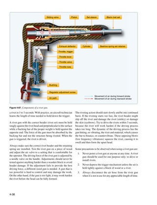
![While traditional tooling has changed little in the past 60 Compression Riveting
years, significant changes have been made in rivet gun Compression riveting (squeezing) is of limited value because
ergonomics. Reduced vibration rivet guns and bucking bars this method of riveting can be used only over the edges of
have been developed to reduce the incidence of carpal tunnel sheets or assemblies where conditions permit, and where the
syndrome and enhance operator comfort. reach of the rivet squeezer is deep enough. The three types
of rivet squeezers—hand, pneumatic, and pneudraulic—
Rivet Sets/Headers operate on the same principles. In the hand rivet squeezer,
Pneumatic guns are used in conjunction with interchangeable compression is supplied by hand pressure; in the pneumatic
rivet sets or headers. Each is designed to fit the type of rivet rivet squeezer, by air pressure; and in the pneudraulic,
and location of the work. The shank of the rivet header is by a combination of air and hydraulic pressure. One jaw
designed to fit into the rivet gun. An appropriate header must is stationary and serves as a bucking bar, the other jaw is
be a correct match for the rivet being driven. The working movable and does the upsetting. Riveting with a squeezer is
face of a header should be properly designed and smoothly a quick method and requires only one operator.
polished. They are made of forged steel, heat treated to be
tough but not too brittle. Flush headers come in various sizes. These riveters are equipped with either a C-yoke or an
Smaller ones concentrate the driving force in a small area for alligator yoke in various sizes to accommodate any size of
maximum efficiency. Larger ones spread the driving force rivet. The working capacity of a yoke is measured by its gap
over a larger area and are used for the riveting of thin skins. and its reach. The gap is the distance between the movable
jaw and the stationary jaw; the reach is the inside length
Nonflush headers should fit to contact about the center two- of the throat measured from the center of the end sets. End
thirds of the rivet head. They must be shallow enough to allow sets for rivet squeezers serve the same purpose as rivet sets
slight upsetting of the head in driving and some misalignment for pneumatic rivet guns and are available with the same
without eyebrowing the riveted surface. Care must be taken to type heads, which are interchangeable to suit any type of
match the size of the rivet. A header that is too small marks rivet head. One part of each set is inserted in the stationary
the rivet; while one too large marks the material. jaw, while the other part is placed in the movable jaws.
The manufactured head end set is placed on the stationary
Rivet headers are made in a variety of styles. [Figure 4-88] The jaw whenever possible. During some operations, it may be
short, straight header is best when the gun can be brought necessary to reverse the end sets, placing the manufactured
close to the work. Offset headers may be used to reach rivets head end set on the movable jaw.
in obstructed places. Long headers are sometimes necessary
when the gun cannot be brought close to the work due to Microshavers
structural interference. Rivet headers should be kept clean. A microshaver is used if the smoothness of the material (such
as skin) requires that all countersunk rivets be driven within
a specific tolerance. [Figure 4-89] This tool has a cutter, a
stop, and two legs or stabilizers. The cutting portion of the
microshaver is inside the stop. The depth of the cut can be
adjusted by pulling outward on the stop and turning it in
either direction (clockwise for deeper cuts). The marks on
Figure 4-88. Rivet headers.
Figure 4-89. Microshaver.
4-39](https://image.slidesharecdn.com/faa-h-8083-31-amt-airframe-vol-1-130226145854-phpapp01/85/Faa-h-8083-31-amt-airframe-vol-1-207-320.jpg)
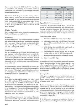
![An important component of team riveting is an efficient The general rule for countersinking and flush fastener
signaling system that communicates the status of the riveting installation procedures has been reevaluated in recent years
process. This signaling system usually consists of tapping because countersunk holes have been responsible for fatigue
the bucking bar against the work and is often called the tap cracks in aircraft pressurized skin. In the past, the general rule
code. One tap may mean not fully seated, hit it again, while for countersinking held that the fastener head must be contained
two taps may mean good rivet, and three taps may mean bad within the outer sheet. A combination of countersinks too deep
rivet, remove and drive another. Radio sets are also available (creating a knife edge), number of pressurization cycles,
for communication between the technicians. fatigue, deterioration of bonding materials, and working
fasteners caused a high stress concentration that resulted in
Once the rivet is installed, there should be no evidence of skin cracks and fastener failures. In primary structure and
rotation of rivets or looseness of riveted parts. After the pressurized skin repairs, some manufacturers are currently
trimming operation, examine for tightness. Apply a force recommending the countersink depth be no more than 2⁄3 the
of 10 pounds to the trimmed stem. A tight stem is one outer sheet thickness or down to 0.020-inch minimum fastener
indication of an acceptable rivet installation. Any degree of shank depth, whichever is greater. Dimple the skin if it is too
looseness indicates an oversize hole and requires replacement thin for machine countersinking. [Figure 4-91]
of the rivet with an oversize shank diameter rivet. A rivet
installation is assumed satisfactory when the rivet head is
seated snugly against the item to be retained (0.005-inch
Preferred
feeler gauge should not go under rivet head for more than countersinking
g
one-half the circumference) and the stem is proved tight.
Countersunk Rivets
An improperly made countersink reduces the strength of a
flush-riveted joint and may even cause failure of the sheet or
the rivet head. The two methods of countersinking commonly
used for flush riveting in aircraft construction and repair are: Permissible
• Machine or drill countersinking. countersinking
• Dimpling or press countersinking.
The proper method for any particular application depends on
the thickness of the parts to be riveted, the height and angle
of the countersunk head, the tools available, and accessibility.
Countersinking Unacceptable
countersinking
When using countersunk rivets, it is necessary to make a
conical recess in the skin for the head. The type of countersink
required depends upon the relation of the thickness of the
sheets to the depth of the rivet head. Use the proper degree
and diameter countersink and cut only deep enough for the Figure 4-91. Countersinking dimensions.
rivet head and metal to form a flush surface.
Keep the rivet high before driving to ensure the force of
Countersinking is an important factor in the design of fastener riveting is applied to the rivet and not to the skin. If the rivet
patterns, as the removal of material in the countersinking is driven while it is flush or too deep, the surrounding skin
process necessitates an increase in the number of fasteners to is work hardened.
assure the required load-transfer strength. If countersinking
is done on metal below a certain thickness, a knife edge with Countersinking Tools
less than the minimum bearing surface or actual enlarging of While there are many types of countersink tools, the most
the hole may result. The edge distance required when using commonly used has an included angle of 100°. Sometimes
countersunk fasteners is greater than when universal head types of 82° or 120° are used to form countersunk wells.
fasteners are used. [Figure 4-84] A six-fluted countersink works best in
aluminum. There are also four- and three-fluted countersinks,
4-41](https://image.slidesharecdn.com/faa-h-8083-31-amt-airframe-vol-1-130226145854-phpapp01/85/Faa-h-8083-31-amt-airframe-vol-1-209-320.jpg)
![but those are harder to control from a chatter standpoint. A Dimpling
single-flute type, such as those manufactured by the Weldon Dimpling is the process of making an indentation or a
Tool Company®, works best for corrosion-resistant steel. dimple around a rivet hole to make the top of the head
[Figure 4-92] of a countersunk rivet flush with the surface of the metal.
Dimpling is done with a male and female die, or forms, often
called punch and die set. The male die has a guide the size of
the rivet hole and is beveled to correspond to the degree of
countersink of the rivet head. The female die has a hole into
which the male guide fits and is beveled to a corresponding
degree of countersink.
When dimpling, rest the female die on a solid surface. Then,
place the material to be dimpled on the female die. Insert the
male die in the hole to be dimpled and, with a hammer, strike
the male die until the dimple is formed. Two or three solid
Figure 4-92. Single-flute countersink.
hammer blows should be sufficient. A separate set of dies is
necessary for each size of rivet and shape of rivet head. An
The microstop countersink is the preferred countersinking alternate method is to use a countersunk head rivet instead
tool. [Figure 4-85] It has an adjustable-sleeve cage that of the regular male punch die, and a draw set instead of the
functions as a limit stop and holds the revolving countersink female die, and hammer the rivet until the dimple is formed.
in a vertical position. Its threaded and replaceable cutters may
have either a removable or an integral pilot that keeps the Dimpling dies for light work can be used in portable
cutter centered in the hole. The pilot should be approximately pneumatic or hand squeezers. [Figure 4-93] If the dies are
0.002-inch smaller than the hole size. It is recommended
to test adjustments on a piece of scrap material before
countersinking repair or replacement parts.
Freehand countersinking is needed where a microstop
countersink cannot fit. This method should be practiced on
scrap material to develop the required skill. Holding the
drill motor steady and perpendicular is as critical during this
operation as when drilling.
Chattering is the most common problem encountered when
countersinking. Some precautions that may eliminate or
minimize chatter include:
• Use sharp tooling.
• Use a slow speed and steady firm pressure.
• Use a piloted countersink with a pilot approximately
0.002-inch smaller than the hole.
• Use back-up material to hold the pilot steady when
countersinking thin sheet material.
• Use a cutter with a different number of flutes.
• Pilot drill an undersized hole, countersink, and then
enlarge the hole to final size.
Figure 4-93. Hand squeezers.
4-42](https://image.slidesharecdn.com/faa-h-8083-31-amt-airframe-vol-1-130226145854-phpapp01/85/Faa-h-8083-31-amt-airframe-vol-1-210-320.jpg)
![used with a squeezer, they must be adjusted accurately to the equipment. The temper of the material, rivet size, and
thickness of the sheet being dimpled. A table riveter is also available equipment are all factors to be considered in
used for dimpling thin skin material and installing rivets. dimpling. [Figure 4-95]
[Figure 4-94]
Male die
Hole
Dimpled hole
Female die
1 2 3
Bucking bar
Figure 4-94. Table riveter.
Coin Dimpling
The coin dimpling, or coin pressing, method uses a
countersink rivet as the male dimpling die. Place the female Gun draw tool Flat gun die
die in the usual position and back it with a bucking bar. Place
the rivet of the required type into the hole and strike the rivet
with a pneumatic riveting hammer. Coin dimpling should Figure 4-95. Dimpling techniques.
be used only when the regular male die is broken or not
available. Coin pressing has the distinct disadvantage of the Hot Dimpling
rivet hole needing to be drilled to correct rivet size before the Hot dimpling is the process that uses heated dimpling dies to
dimpling operation is accomplished. Since the metal stretches ensure the metal flows better during the dimpling process. Hot
during the dimpling operation, the hole becomes enlarged and dimpling is often performed with large stationary equipment
the rivet must be swelled slightly before driving to produce available in a sheet metal shop. The metal being used is
a close fit. Because the rivet head causes slight distortions in an important factor because each metal presents different
the recess, and these are characteristic only to that particular dimpling problems. For example, 2024-T3 aluminum alloy
rivet head, it is wise to drive the same rivet that was used as can be satisfactorily dimpled either hot or cold, but may crack
the male die during the dimpling process. Do not substitute in the vicinity of the dimple after cold dimpling because of
another rivet, either of the same size or a size larger. hard spots in the metal. Hot dimpling prevents such cracking.
Radius Dimpling 7075-T6 aluminum alloys are always hot dimpled.
Radius dimpling uses special die sets that have a radius Magnesium alloys also must be hot dimpled because, like
and are often used with stationary or portable squeezers. 7075-T6, they have low formability qualities. Titanium is
Dimpling removes no metal and, due to the nestling effect, another metal that must be hot dimpled because it is tough
gives a stronger joint than the non-flush type. A dimpled joint and resists forming. The same temperature and dwell time
reduces the shear loading on the rivet and places more load used to hot dimple 7075-T6 is used for titanium.
on the riveted sheets.
100° Combination Predimple and Countersink Method
NOTE: Dimpling is also done for flush bolts and other Metals of different thicknesses are sometimes joined
flush fasteners. by a combination of dimpling and countersinking.
[Figure 4-96] A countersink well made to receive a dimple
Dimpling is required for sheets that are thinner than the is called a subcountersink. These are most often seen where
minimum specified thickness for countersinking. However, a thin web is attached to heavy structure. It is also used on
dimpling is not limited to thin materials. Heavier parts may thin gap seals, wear strips, and repairs for worn countersinks.
be dimpled without cracking by specialized hot dimpling
4-43](https://image.slidesharecdn.com/faa-h-8083-31-amt-airframe-vol-1-130226145854-phpapp01/85/Faa-h-8083-31-amt-airframe-vol-1-211-320.jpg)
![common in 2024-T3. A rough hole or a dimple that
This top sheet is dimpled is too deep causes such cracks. A small tolerance is
usually allowed for radial cracks.
• Circumferential cracks—downward bending into the
draw die causes tension stresses in the upper portion
of the metal. Under some conditions, a crack may
be created that runs around the edge of the dimple.
Such cracks do not always show since they may be
Thick bottom material is countersunk underneath the cladding. When found, they are cause
for rejection. These cracks are most common in hot-
dimpled 7075 T6 aluminum alloy material. The usual
Figure 4-96. Predimple and countersink method. cause is insufficient dimpling heat.
Dimpling Inspection
To determine the quality of a dimple, it is necessary to make Evaluating the Rivet
a close visual inspection. Several features must be checked. To obtain high structural efficiency in the manufacture and
The rivet head should fit flush and there should be a sharp repair of aircraft, an inspection must be made of all rivets
break from the surface into the dimple. The sharpness of the before the part is put in service. This inspection consists of
break is affected by dimpling pressure and metal thickness. examining both the shop and manufactured heads and the
Selected dimples should be checked by inserting a fastener to surrounding skin and structural parts for deformities. A scale
make sure that the flushness requirements are met. Cracked or rivet gauge can be used to check the condition of the upset
dimples are caused by poor dies, rough holes, or improper rivet head to see that it conforms to the proper requirements.
heating. Two types of cracks may form during dimpling: Deformities in the manufactured head can be detected by the
trained eye alone. [Figure 4-97]
• Radial cracks—start at the edge and spread outward as
the metal within the dimple stretches. They are most
A. Driven correctly B. Unsteady tool C. Driven excessively D. Separation of sheets E. Unsteady rivet set F. Excessive shank length
Top view
Damaged
head
Side view
w
Swelled shank
Si
Cracks Sloping head Buckled shank
view
Bottom view
Imperfection Cause Remedy Action
A None None None None
B Cut head Improperly held tools Hold riveting tools firmly against work Replace rivet
C Excessively flat head, Excessive driving, too much pressure on Improve riveting technique Replace rivet
resultant head cracks bucking bar
D Sheet separation Work not held firmly together and rivet Fasten work firmly together to prevent Replace rivet
shank swelled slipping
E Sloping head a. Bucking bar not held firmly Hold bucking bar firmly without too Replace rivet
b. Bucking bar permitted to slide and much pressure
bounce over the rivet
F Buckled shank Improper rivet length, and E above E above and rivet of proper length Replace rivet
Figure 4-97. Rivet defects.
4-44](https://image.slidesharecdn.com/faa-h-8083-31-amt-airframe-vol-1-130226145854-phpapp01/85/Faa-h-8083-31-amt-airframe-vol-1-212-320.jpg)
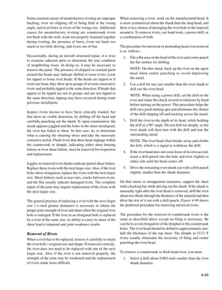
![Rivet Removal
Remove rivets by drilling off the head and punching out the shank as illustrated.
1. File a flat area on the manufactured head of non-flush rivets.
2. Place a block of wood or a bucking bar under both flush and nonflush rivets when center punching the manufactured head.
3. Use a drill that is 1/32 (0.0312) inch smaller than the rivet shank to drill through the head of the rivet. Ensure the drilling
operation does not damage the skin or cut the sides of the rivet hole.
4. Insert a drift punch into the hole drilled in the rivet and tilt the punch to break off the rivet head.
5. Using a drift punch and hammer, drive out the rivet shank. Support the opposite side of the structure to prevent
structural damage.
1. File a flat area on manufactured head 2. Center punch flat
5. Punch out rivet with machine punch
3. Drill through head using drill one 4. Remove weakened head with
size smaller than rivet shank machine punch
Figure 4-98. Rivet removal.
2. Drill into the exact center of the rivet head to the the next larger size rivet. Do not replace a rivet with a type
approximate depth of the head. having lower strength properties, unless the lower strength
3. Remove the head by breaking it off. Use a punch as is adequately compensated by an increase in size or a greater
a lever. number of rivets. It is acceptable to replace 2017 rivets of
3
⁄16-inch diameter or less, and 2024 rivets of 5⁄32-inch diameter
4. Punch out the shank. Use a suitable backup, preferably or less with 2117 rivets for general repairs, provided the
wood (or equivalent), or a dedicated backup block. If replacement rivets are 1⁄32-inch greater in diameter than the
the shank does not come out easily, use a small drill rivets they replace.
and drill through the shank. Be careful not to elongate
the hole. National Advisory Committee for Aeronautics
(NACA) Method of Double Flush Riveting
Replacing Rivets
A rivet installation technique known as the National Advisory
Replace rivets with those of the same size and strength
Committee for Aeronautics (NACA) method has primary
whenever possible. If the rivet hole becomes enlarged,
applications in fuel tank areas. [Figure 4-99] To make
deformed, or otherwise damaged, drill or ream the hole for
4-46](https://image.slidesharecdn.com/faa-h-8083-31-amt-airframe-vol-1-130226145854-phpapp01/85/Faa-h-8083-31-amt-airframe-vol-1-214-320.jpg)
![Shop head formed in countersink
Rivet factory head
Figure 4-99. NACA riveting method.
a NACA rivet installation, the shank is upset into a 82°
countersink. In driving, the gun may be used on either the Figure 4-101. Assorted fasteners.
head or shank side. The upsetting is started with light blows,
Special purpose fasteners are sometimes lighter than solid
then the force increased and the gun or bar moved on the
shank rivets, yet strong enough for their intended use. These
shank end so as to form a head inside the countersink well. If
fasteners are manufactured by several corporations and
desired, the upset head may be shaved flush after driving. The
have unique characteristics that require special installation
optimal strength is achieved by cutting the countersink well
tools, special installation procedures, and special removal
to the dimensions given in Figure 4-100. Material thickness
procedures. Because these fasteners are often inserted in
minimums must be carefully adhered to.
locations where one head, usually the shop head, cannot be
seen, they are called blind rivets or blind fasteners.
Rivet Size Minimum Thickness Countersink Diameter
± .005
3/32 .032 .141
Typically, the locking characteristics of a blind rivet are not
as good as a driven rivet. Therefore, blind rivets are usually
1/8 .040 .189
not used when driven rivets can be installed. Blind rivets
5/32 .050 .236
shall not be used:
3/16 .063 .288
1. In fluid-tight areas.
1/4 .090 .400
2. On aircraft in air intake areas where rivet parts may
Figure 4-100. Material thickness minimums, in inches, for NACA be ingested by the engine.
riveting method using 82° countersink. 3. On aircraft control surfaces, hinges, hinge brackets,
flight control actuating systems, wing attachment
Special Purpose Fasteners fittings, landing gear fittings, on floats or amphibian
Special purpose fasteners are designed for applications in hulls below the water level, or other heavily stressed
which fastener strength, ease of installation, or temperature locations on the aircraft.
properties of the fastener require consideration. Solid shank
rivets have been the preferred construction method for metal NOTE: For metal repairs to the airframe, the use of blind
aircraft for many years because they fill up the hole, which rivets must be specifically authorized by the airframe
results in good load transfer, but they are not always ideal. manufacturer or approved by a representative of the Federal
For example, the attachment of many nonstructural parts Aviation Administration (FAA).
(aircraft interior furnishings, flooring, deicing boots, etc.) do
not need the full strength of solid shank rivets. Blind Rivets
The first blind fasteners were introduced in 1940 by the
To install solid shank rivets, the aircraft technician must Cherry Rivet Company (now Cherry® Aerospace), and the
have access to both sides of a riveted structure or structural aviation industry quickly adopted them. The past decades
part. There are many places on an aircraft where this access have seen a proliferation of blind fastening systems based on
is impossible or where limited space does not permit the use the original concept, which consists of a tubular rivet with
of a bucking bar. In these instances, it is not possible to use a fixed head and a hollow sleeve. Inserted within the rivet’s
solid shank rivets, and special fasteners have been designed core is a stem that is enlarged or serrated on its exposed end
that can be bucked from the front. [Figure 4-101] There are when activated by a pulling-type rivet gun. The lower end
also areas of high loads, high fatigue, and bending on aircraft. of the stem extends beyond the inner sheet of metal. This
Although the shear loads of riveted joints are very good, the
tension, or clamp-up, loads are less than ideal.
4-47](https://image.slidesharecdn.com/faa-h-8083-31-amt-airframe-vol-1-130226145854-phpapp01/85/Faa-h-8083-31-amt-airframe-vol-1-215-320.jpg)
![portion contains a tapered joining portion and a blind head
that has a larger diameter than the stem or the sleeve of the
tubular rivet.
When the pulling force of the rivet gun forces the blind head
upward into the sleeve, its stem upsets or expands the lower
end of the sleeve into a tail. This presses the inner sheet
upward and closes any space that might have existed between
it and the outer sheet. Since the exposed head of the rivet is
held tightly against the outer sheet by the rivet gun, the sheets
of metal are clamped, or clinched, together.
NOTE: Fastener manufacturers use different terminology to
describe the parts of the blind rivet. The terms “mandrel,”
“spindle,” and “stem” are often used interchangeably. For
clarity, the word “stem” is used in this handbook and refers
to the piece that is inserted into the hollow sleeve.
Friction-Locked Blind Rivets
Standard self-plugging blind rivets consist of a hollow sleeve
and a stem with increased diameter in the plug section. Figure 4-102. Friction-lock blind rivet.
The blind head is formed as the stem is pulled into the that locks the center stem into place when installed. Bulbed,
sleeve. Friction-locked blind rivets have a multiple-piece self-plugging, mechanically-locked blind rivets form a large,
construction and rely on friction to lock the stem to the blind head that provides higher strength in thin sheets when
sleeve. As the stem is drawn up into the rivet shank, the installed. They may be used in applications where the blind
stem portion upsets the shank on the blind side, forming a head is formed against a dimpled sheet.
plug in the hollow center of the rivet. The excess portion of
the stem breaks off at a groove due to the continued pulling Manufacturers such as Cherry® Aerospace (CherryMAX®,
action of the rivet gun. Metals used for these rivets are 2117- CherryLOCK®, Cherry SST®) and Alcoa Fastening Systems
T4 and 5056-F aluminum alloy. Monel® is used for special (Huck-Clinch ® , HuckMax ® , Unimatic ® ) make many
applications. variations of this of blind rivet. While similar in design, the
tooling for these rivets is often not interchangeable.
Many friction-locked blind rivet center stems fall out due to
vibration, which greatly reduces its shear strength. To combat The CherryMAX® Bulbed blind rivet is one of the earlier
that problem, most friction-lock blind rivets are replaced by types of mechanical-lock blind rivets developed. Their main
the mechanical-lock, or stem-lock, type of blind fasteners. advantage is the ability to replace a solid shank rivet size
However, some types, such as the Cherry SPR® 3⁄32-inch for size. The CherryMAX® Bulbed blind rivet consists of
Self-Plugging Rivet, are ideal for securing nutplates located four parts:
in inaccessible and hard-to-reach areas where bucking or
squeezing of solid rivets is unacceptable. [Figure 4-102] 1. A fully serrated stem with break notch, shear ring, and
integral grip adjustment cone.
Friction-lock blind rivets are less expensive than mechanical- 2. A driving anvil to ensure a visible mechanical lock
lock blind rivets and are sometimes used for nonstructural with each fastener installation.
applications. Inspection of friction-lock blind rivets is 3. A separate, visible, and inspectable locking collar that
visual. A more detailed discussion on how to inspect riveted mechanically locks the stem to the rivet sleeve.
joints can be found in the section, General Repair Practices.
Removal of friction-lock blind rivets consists of punching out 4. A rivet sleeve with recess in the head to receive the
the friction-lock stem and then treating it like any other rivet. locking collar.
Mechanical-Lock Blind Rivets It is called a bulbed fastener due to its large blind side
bearing surface, developed during the installation process.
The self-plugging, mechanical-lock blind rivet was developed
These rivets are used in thin sheet applications and for use
to prevent the problem of losing the center stem due to
in materials that may be damaged by other types of blind
vibration. This rivet has a device on the puller or rivet head
4-48](https://image.slidesharecdn.com/faa-h-8083-31-amt-airframe-vol-1-130226145854-phpapp01/85/Faa-h-8083-31-amt-airframe-vol-1-216-320.jpg)
![rivets. This rivet features a safe-lock locking collar for more The stem and rivet sleeve work as an assembly to provide
reliable joint integrity. The rough end of the retained stem radial expansion and a large bearing footprint on the blind
in the center on the manufactured head must never be filed side of the fastened surface. The lock collar ensures that the
smooth because it weakens the strength of the lockring, and stem and sleeve remain assembled during joint loading and
the center stem could fall out. unloading. Rivet sleeves are made from 5056 aluminum,
Monel® and INCO 600. The stems are made from alloy
CherryMAX® bulbed rivets are available in three head styles: steel, CRES, and INCO® X-750. CherryMAX® rivets have
universal, 100° countersunk, and 100° reduced shear head an ultimate shear strength ranging from 50 KSI to 75 KSI.
styles. Their lengths are measured in increments of 1⁄16 inch.
It is important to select a rivet with a length related to the Removal of Mechanically Locked Blind Rivets
grip length of the metal being joined. This blind rivet can Mechanically locked blind rivets are a challenge to remove
be installed using either the Cherry® G750A or the newly because they are made from strong, hard metals. Lack of
released Cherry® G800 hand riveters, or either the pneumatic- access poses yet another problem for the aviation technician.
hydraulic G704B or G747 CherryMAX® power tools. For Designed for and used in difficult to reach locations means
installation, please refer to Figure 4-103. there is often no access to the blind side of the rivet or any way
to provide support for the sheet metal surrounding the rivet’s
The CherryMAX® mechanical-lock blind rivet is popular location when the aviation technician attempts removal.
with general aviation repair shops because it features the
one tool concept to install three standard rivet diameters and The stem is mechanically locked by a small lock ring that
their oversize counterparts. [Figure 4-104] CherryMAX® needs to be removed first. Use a small center drill to provide
rivets are available in four nominal diameters: 1⁄8, 5⁄32, 3⁄16, and a guide for a larger drill on top of the rivet stem and drill
1
⁄4-inch and three oversized diameters and four head styles: away the upper portion of the stem to destroy the lock. Try
universal, 100° flush head, 120° flush head, and NAS1097 to remove the lock ring or use a prick punch or center punch
flush head. This rivet consists of a blind header, hollow rivet to drive the stem down a little and remove the lock ring.
shell, locking (foil) collar, driving anvil, and pulling stem After the lock ring is removed, the stem can be driven out
complete with wrapped locking collar. The rivet sleeve and with a drive punch. After the stem is removed, the rivet can
the driving washer blind bulbed header takes up the extended be drilled out in the same way as a solid rivet. If possible,
shank and forms the bucktail. support the back side of the rivet with a backup block to
prevent damage to the aircraft skin.
1 2 3 4
The continued pulling action of
the installation tool causes the
stem shear ring to shear from
the main body of the stem as
The CherryMAX® rivet is The pulling head holds the the stem continues to move The safe-lock locking collar
inserted into the prepared rivet sleeve in place as it through the rivet sleeve. This fills the rivet sleeve head
hole. The pulling head begins to pull the rivet stem action allows the fastener to recess, locking the stem and
(installation tool) is slipped into the rivet sleeve. This accommodate a minimum of rivet sleeve securely together.
over the rivet’s stem. pulling action causes the 1/16" variation in structure Continued pulling by the
Applying a firm, steady stem shear ring to upset the thickness. The locking collar installation tool causes the
pressure, which seats the rivet sleeve and form the then contacts the driving anvil. stem to fracture at the break
rivet head, the installation bulbed blind head. As the stem continues to be notch, providing a flush,
tool is then actuated. pulled by the action of the burr-free, inspectable
installation tool, the Safe-Lock installation.
locking collar deforms into the
rivet sleeve head recess.
Figure 4-103. CherryMax® installation procedure.
4-49](https://image.slidesharecdn.com/faa-h-8083-31-amt-airframe-vol-1-130226145854-phpapp01/85/Faa-h-8083-31-amt-airframe-vol-1-217-320.jpg)
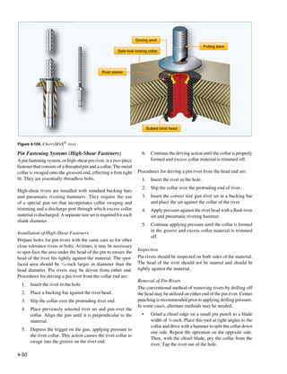
![• Use a special hollow punch having one or more blades The advantages of Hi-Lok® two-piece fastener include its
placed to split the collar. Pry the collar from the groove light weight, high fatigue resistance, high strength, and its
and tap out the rivet. inability to be overtorqued. The pins, made from alloy steel,
• Sharpen the cutting blades of a pair of nippers. Cut corrosion resistant steel, or titanium alloy, come in many
the collar in two pieces or use nippers at right angles standard and oversized shank diameters. The collars are made
to the rivet and cut through the small neck. of aluminum alloy, corrosion resistant steel, or alloy steel.
The collars have wrenching flats, fracture point, threads, and
• A hollow-mill collar cutter can be used in a power hand a recess. The wrenching flats are used to install the collar.
drill to cut away enough collar material to permit the The fracture point has been designed to allow the wrenching
rivet to be tapped out of the work. flats to shear when the proper torque has been reached. The
threads match the threads of the pins and have been formed
The high-shear pin rivet family includes fasteners, such as into an ellipse that is distorted to provide the locking action.
the Hi-Lok®, Hi-Tigue®, and Hi-Lite® made by Hi-Shear The recess serves as a built-in washer. This area contains a
Corporation and the CherryBUCK® 95 KSI One-Piece Shear portion of the shank and the transition area of the fastener.
Pin and Cherry E-Z Buck® Shear Pin made by Cherry®
Aerospace. The hole shall be prepared so that the maximum interference
fit does not exceed 0.002-inch. This avoids build up of
Hi-Lok® Fastening System excessive internal stresses in the work adjacent to the hole.
The threaded end of the Hi-Lok® two-piece fastener contains The Hi-Lok® pin has a slight radius under its head to increase
a hexagonal shaped recess. [Figure 4-105] The hex tip of an fatigue life. After drilling, deburr the edge of the hole to allow
Allen wrench engages the recess to prevent rotation of the the head to seat fully in the hole. The Hi-Lok® is installed in
pin while the collar is being installed. The pin is designed interference fit holes for aluminum structure and a clearance
in two basic head styles. For shear applications, the pin is fit for steel, titanium, and composite materials.
made in countersunk style and in a compact protruding head
style. For tension applications, the MS24694 countersunk and Hi-Tigue® Fastening System
regular protruding head styles are available. The Hi-Tigue® fastener offers all of the benefits of the Hi-
Lok® fastening system along with a unique bead design that
enhances the fatigue performance of the structure making
it ideal for situations that require a controlled interference
fit. The Hi-Tigue® fastener assembly consists of a pin and
collar. These pin rivets have a radius at the transition area.
During installation in an interference fit hole, the radius area
will “cold work” the hole. These fastening systems can be
easily confused, and visual reference should not be used for
identification. Use part numbers to identify these fasteners.
Hi-Lite® Fastening System
The Hi-Lite® fastener is similar in design and principle to
the Hi-Lok® fastener, but the Hi-Lite® fastener has a shorter
transition area between the shank and the first load-bearing
Figure 4-105. Hi-Lok®.
thread. Hi-Lite® has approximately one less thread. All Hi-
Lite® fasteners are made of titanium.
The self-locking, threaded Hi-Lok® collar has an internal
counterbore at the base to accommodate variations in
These differences reduce the weight of the Hi-Lite® fastener
material thickness. At the opposite end of the collar is a
without lessening the shear strength, but the Hi-Lite®
wrenching device that is torqued by the driving tool until it
clamping forces are less than that of a Hi-Lok® fastener.
shears off during installation, leaving the lower portion of
The Hi-Lite® collars are also different and thus are not
the collar seated with the proper torque without additional
interchangeable with Hi-Lok® collars. Hi-Lite® fasteners can
torque inspection. This shear-off point occurs when a
be replaced with Hi-Lok® fasteners for most applications, but
predetermined preload or clamp-up is attained in the fastener
Hi-Loks® cannot be replaced with Hi-Lites®.
during installation.
4-51](https://image.slidesharecdn.com/faa-h-8083-31-amt-airframe-vol-1-130226145854-phpapp01/85/Faa-h-8083-31-amt-airframe-vol-1-219-320.jpg)
![CherryBUCK® 95 KSI One-Piece Shear Pin used for similar applications. Lockbolts are made in various
The CherryBUCK® is a bimetallic, one-piece fastener that head styles, alloys, and finishes.
combines a 95 KSI shear strength shank with a ductile,
titanium-columbium tail. Theses fasteners are functionally The lockbolt requires a pneumatic hammer or pull gun
interchangeable with comparable 6AI-4V titanium alloy for installation. Lockbolts have their own grip gauge
two-piece shear fasteners, but with a number of advantages. and an installation tool is required for their installation.
Their one piece design means no foreign object damage [Figure 4-107] When installed, the lockbolt is rigidly and
(FOD), it has a 600 °F allowable temperature, and a very permanently locked in place. Three types of lockbolts are
low backside profile. commonly used: pull-type, stump-type, and blind-type.
Lockbolt Fastening Systems
10
2
4
6
12
14
8
16
18
20
22
24
26
28
30
32
34
36
38
40
42
44
46
48
48
46
44
42
40
38
36
34
32
30
28
26
24
22
20
18
16
14
12
10
8
6
4
2
Also pioneered in the 1940s, the lockbolt is a two-piece GRIP SCALE
INCH SCALE
46
44
42
40
38
36
34
32
30
28
26
24
22
20
18
16
14
12
10
fastener that combines the features of a high strength bolt and
8
6
4
2
a rivet with advantages over each. [Figure 4-106] In general,
a lockbolt is a nonexpanding fastener that has either a collar
Figure 4-107. Lockbolt grip gauge.
swaged into annular locking groves on the pin shank or a type
of threaded collar to lock it in place. Available with either
countersunk or protruding heads, lockbolts are permanent The pull-type lockbolt is mainly used in aircraft and primary
type fasteners assemblies and consist of a pin and a collar. and secondary structure. It is installed very rapidly and has
approximately one-half the weight of equivalent AN steel
bolts and nuts. A special pneumatic pull gun is required for
installation of this type lockbolt, which can be performed by
one operator since buckling is not required.
The stump-type lockbolt, although not having the extended
stem with pull grooves, is a companion fastener to the pull-
type lockbolt. It is used primarily where clearance does not
permit effective installation of the pull-type lockbolt. It is
Shear and tension Shear and tension
driven with a standard pneumatic riveting hammer, with
pull-type pins stump-type pins a hammer set attached for swaging the collar into the pin
locking grooves, and a bucking bar.
Figure 4-106. Lockbolts.
The blind-type lockbolt comes as a complete unit or
A lockbolt is similar to an ordinary rivet in that the locking assembly and has exceptional strength and sheet pull-together
collar, or nut, is weak in tension and it is difficult to remove characteristics. Blind-type lockbolts are used where only
once installed. Some of the lockbolts are similar to blind one side of the work is accessible and generally where it is
rivets and can be completely installed from one side. Others difficult to drive a conventional rivet. This type lockbolt is
are fed into the workpiece with the manufactured head on the installed in a manner similar to the pull-type lockbolt.
far side. The installation is completed on the near side with
a gun similar to blind rivet gun. The lockbolt is easier and The pins of pull- and stump-type lockbolts are made of
more quickly installed than the conventional rivet or bolt and heat-treated alloy steel or high-strength aluminum alloy.
eliminates the use of lockwashers, cotter pins, and special Companion collars are made of aluminum alloy or mild steel.
nuts. The lockbolt is generally used in wing splice fittings, The blind-type lockbolt consists of a heat-treated alloy steel
landing gear fittings, fuel cell fittings, longerons, beams, skin pin, blind sleeve, filler sleeve, mild steel collar, and carbon
splice plates, and other major structural attachment. steel washer.
Often called huckbolts, lockbolts are manufactured by These fasteners are used in shear and tension applications.
companies such as Cherry® Aerospace (Cherry® Lockbolt), The pull type is more common and can be installed by one
Alcoa Fastening Systems (Hucktite® Lockbolt System), person. The stump type requires a two person installation.
and SPS Technologies. Used primarily for heavily stressed An assembly tool is used to swage the collar onto the serrated
structures that require higher shear and clamp-up values than grooves in the pin and break the stem flush to the top of the
can be obtained with rivets, the lockbolt and Hi-lok® are often collar.
4-52](https://image.slidesharecdn.com/faa-h-8083-31-amt-airframe-vol-1-130226145854-phpapp01/85/Faa-h-8083-31-amt-airframe-vol-1-220-320.jpg)
![The easiest way to differentiate between tension and shear
R
pins is the number of locking groves. Tension pins normally
Z
have four locking grooves and shear pins have two locking
grooves. The installation tooling preloads the pin while
swaging the collar. The surplus end of the pin, called the
Y
pintail, is then fractured. T
Installation Procedure
Installation of lockbolts involves proper drilling. The hole
preparation for a lockbolt is similar to hole preparation for a
Hi-Lok®. An interference fit is typically used for aluminum Lockbolt/Collar Acceptan Criteria
kbolt/Collar Acceptance
and a clearance fit is used for steel, titanium, and composite Nominal Y Z R T
Fastener Diameter (Ref.) Max. Min.
materials. [Figure 4-108]
5/32 .324/.161 .136 .253 .037
Lockbolt Inspection 3/16 .280/.208 .164 .303 .039
After installation, a lockbolt needs to be inspected to 1/4 .374/.295 .224 .400 .037
determine if installation is satisfactory. [Figure 4-109] 5/16 .492/.404 .268 .473 .110
Inspect the lockbolt as follows: 3/8 .604/.507 .039 .576 .120
1. The head must be firmly seated.
Figure 4-109. Lockbolt inspection.
2. The collar must be tight against the material and have
the proper shape and size. The Eddie-Bolt® 2 Pin Fastening System
3. Pin protrusion must be within limits. The Eddie-Bolt® 2 looks similar to the Hi-Lok®, but has five
flutes, equally spaced along a portion of the pin thread area.
A companion threaded collar deforms into the flutes at a
Lockbolt Removal
predetermined torque and locks the collar in place. The collar
The best way to remove a lockbolt is to remove the collar and
can be unscrewed using special tooling. This fastening system
drive out the pin. The collar can be removed with a special
can be used in either clearance or interference-fit holes.
collar cutter attached to a drill motor that mills off the collar
without damaging the skin. If this is not possible, a collar
splitter or small chisel can be used. Use a backup block on
the opposite side to prevent elongation of the hole.
1 2 3 4
Placed the pin in the hole
from the back side of the
work and slip the collar on. The initial pull draws the work Further pull swages the collar
The hold-off head must be up tight and pulls that portion into the locking grooves to
toward the gun. This allows of the shank under the head form a permanent lock. Continued force breaks the
the gun to preload the pin into the hole. pin and ejects the tail. Anvil
before swaging. Then apply returns and disengages from
the gun; the chuck jaws the swaged collar.
engage the pull grooves of
the projecting pintail. Hold
the gun loosely and pull the
trigger.
Figure 4-108. Lockbolt installation procedure.
4-53](https://image.slidesharecdn.com/faa-h-8083-31-amt-airframe-vol-1-130226145854-phpapp01/85/Faa-h-8083-31-amt-airframe-vol-1-221-320.jpg)
![Blind Bolts Blind Bolt and the Unimatic® Advanced Bolt (UAB) blind
Bolts are threaded fasteners that support loads through pre- bolt systems.
drilled holes. Hex, close-tolerance, and internal wrenching
bolts are used in aircraft structural applications. Blind bolts Cherry Maxibolt® Blind Bolt System
have a higher strength than blind rivets and are used for The Cherry Maxibolt® blind bolt, available in alloy steel
joints that require high strength. Sometimes, these bolts can and A-286 CRES materials, comes in four different nominal
be direct replacements for the Hi-Lok® and lockbolt. Many and oversized head styles. [Figure 4-110] One tool and
of the new generation blind bolts are made from titanium pulling head installs all three diameters. The blind bolts
and rated at 90 KSI shear strength, which is twice as much create a larger blind side footprint and they provide excellent
as most blind rivets. performance in thin sheet and nonmetallic applications. The
flush breaking stem eliminates shaving while the extended
Determining the correct length of the fastener is critical to grip range accommodates different application thicknesses.
correct installation. The grip length of a bolt is the distance Cherry Maxibolts® are primarily used in structures where
from the underhead bearing surface to the first thread. The higher loads are required. The steel version is 112 KSI shear.
grip is the total thickness of material joined by the bolt. The A286 version is 95 KSI shear. The Cherry® G83, G84,
Ideally, the grip length should be a few thousands of an inch or G704 installation tools are required for installation.
less than the actual grip to avoid bottoming the nut. Special
grip gauges are inserted in the hole to determine the length Huck Blind Bolt System
of the blind bolt to be used. Every blind bolt system has its The Huck Blind Bolt is a high strength vibration-resistant
own grip gauge and is not interchangeable with other blind fastener. [Figure 4-111] These bolts have been used
bolt or rivet systems. successfully in many critical areas, such as engine inlets and
leading edge applications. All fasteners are installed with a
Blind bolts are difficult to remove due to the hardness of combination of available hand, pneumatic, pneudraulic, or
the core bolt. A special removal kit is available from the hydraulic pull-type tools (no threads) for ease of installation.
manufacturer for removing each type of blind bolt. These kits
make it easier to remove the blind bolt without damaging the Huck Blind Bolts can be installed on blind side angle
hole and parent structure. Blind bolts are available in a pull surfaces up to 5° without loss of performance. The stem is
type and a drive type. mechanically locked to provide vibration-resistant FOD-free
installations. The locking collar is forced into a conical pocket
Pull-Type Blind Bolt between stem and sleeve, creating high tensile capability. The
Several companies manufacture the pull-type of blind bolt lock collar fills the sleeve lock pocket to prevent leakage or
fastening systems. They may differ in some design aspects, corrosion pockets (crevice corrosion).
but in general they have a similar function. The pull-type uses
the drive nut concept and is composed of a nut, sleeve, and Flush head blind bolts are designed to install with a flush
a draw bolt. Frequently used blind bolt systems include but stem break that often requires no trimming for aerodynamic
are not limited to the Cherry Maxibolt® Blind Bolt system surfaces. The Huck Blind Bolt is available in high-strength
and the HuckBolt® fasteners which includes the Ti-Matic® A286 CRES at 95KSI shear strength in 5⁄32-inch through 3⁄8-
During the Maxibolt® installation sequence, the Cherry®
shift washer collapses into itself, leaving a solid washer
that is easily retrieved.
Figure 4-110. Maxibolt® Blind Bolt System installation.
4-54](https://image.slidesharecdn.com/faa-h-8083-31-amt-airframe-vol-1-130226145854-phpapp01/85/Faa-h-8083-31-amt-airframe-vol-1-222-320.jpg)
![inch diameters in 100° flush tension and protruding head. Drive Nut-Type of Blind Bolt
Also available are shear flush heads in 3⁄16-inch diameter. Jo-bolts, Visu-lok®, Composi-Lok®, OSI Bolt®, and Radial-
A286 CRES Huck Blind Bolts are also available in 1⁄64-inch Lok® fasteners use the drive nut concept and are composed of
oversize diameters for repair applications. a nut, sleeve, and a draw bolt. [Figure 4-112] These types of
blind bolts are used for high strength applications in metals
and composites when there is no access to the blind side.
Drive anvil washer Break neck Expander
Available in steel and titanium alloys, they are installed with
Gold color = Nominal diameter
Silver color = Offset diameter special tooling. Both powered and hand tooling is available.
During installation, the nut is held stationary while the core
Pull grooves
bolt is rotated by the installation tooling. The rotation of the
core bolt draws the sleeve into the installed position and
continues to retain the sleeve for the life of the fastener. The
bolt has left hand threads and driving flats on the threaded
Retention splines end. A break-off relief allows the driving portion of the
bolt to break off when the sleeve is properly seated. These
Lockring (visible after installation) types of bolts are available in many different head styles,
1 including protruding head, 100° flush head, 130° flush head,
Rivet inserted into clearance hole—tool is engaged.
engaged and hex head.
2
Expander enters sleeve—upset starts to form.
nder
3 Figure 4-112. Drive nut blind bolt.
Upset continues to form—lock starts to form.
Use the grip gauge available for the type of fastener and
select the bolt grip after careful determination of the
material thickness. The grip of the bolt is critical for correct
installation. [Figure 4-113]
4
Upset complete—lock completely formed.
5
Pin breaks flush, lock visible—installation complete.
ck com
Figure 4-113. Drive nut blind bolt installation tool.
Figure 4-111. Huck blind bolt system.
4-55](https://image.slidesharecdn.com/faa-h-8083-31-amt-airframe-vol-1-130226145854-phpapp01/85/Faa-h-8083-31-amt-airframe-vol-1-223-320.jpg)
![Installation procedure: Rivet Nut
1. Install the fastener into the hole, and place the The rivet nut is a blind installed, internally threaded rivet
installation tooling over the screw (stem) and nut. invented in 1936 by the Goodrich Rubber Company for the
purpose of attaching a rubber aircraft wing deicer extrusion
2. Apply torque to the screw with the installation tool
to the leading edge of the wing. The original rivet nut is the
while keeping the drive nut stationary. The screw
Rivnut® currently manufactured by Bollhoff Rivnut Inc. The
continues to advance through the nut body causing
Rivnut® became widely used in the military and aerospace
the sleeve to be drawn up over the tapered nose of
markets because of its many design and assembly advantages.
the nut. When the sleeve forms tightly against the
blind side of the structure, the screw fractures in the
Rivet nuts are used for the installation of fairings, trim, and
break groove. The stem of Jo-bolts, Visu-lok®, and
lightly loaded fittings that must be installed after an assembly
Composi-Lok® II fasteners does not break off flush
is completed. [Figure 4-114] Often used for parts that are
with the head. A screw break-off shaver tool must be
removed frequently, the rivet nut is available in two types:
used if a flush installation is required. The stem of the
countersunk or flat head. Installed by crimping from one side,
newer Composi-Lok3® and OSI Bolt® break off flush.
the rivet nut provides a threaded hole into which machine
screws can be installed. Where a flush fit is required, the
Tapered Shank Bolt
countersink style can be used. Rivet nuts made of alloy steel
Tapered shank bolts, such as the Taper-Lok®, are lightweight, are used when increased tensile and shear strength is required.
high strength shear or tension bolts. This bolt has a tapered
shank designed to provide an interference fit upon installation.
Tapered shank bolts can be identified by a round head (rather
than a screwdriver slot or wrench flats) and a threaded shank.
The Taper-Lok® is comprised of a tapered, conical-shank
fastener, installed into a precision tapered hole. The use of
tapered shank bolts is limited to special applications such as
high stress areas of fuel tanks. It is important that a tapered
bolt not be substituted for any other type of fastener in repairs.
It is equally as important not to substitute any other type of
fastener for a tapered bolt.
Tapered shank bolts look similar to Hi-Lok® bolts after
installation, but the tapered shank bolts do not have the hex
Figure 4-114. Rivet nut installation.
recess at the threaded end of the bolt. Tapered shank bolts
are installed in precision-reamed holes, with a controlled Hole Preparation
interference fit. The interference fit compresses the material
Flat head rivet nuts require only the proper size of hole while
around the hole that results in excellent load transfer, fatigue
flush installation can be made into either countersunk or
resistance, and sealing. The collar used with the tapered shank
dimpled skin. Metal thinner than the rivet nut head requires
bolts has a captive washer, and no extra washers are required.
a dimple. The rivet nut size is selected according to the
New tapered shank bolt installation or rework of tapered shank
thickness of the parent material and the size of screw to be
bolt holes needs to be accomplished by trained personnel.
used. The part number identifies the type of rivet nut and the
Properly installed, these bolts become tightly wedged and do
maximum grip length. Recommended hole sizes are shown
not turn while torque is applied to the nut.
in Figure 4-115.
Sleeve Bolts Rivnut® Size Drill Size Hole Tolerance
Sleeve bolts are used for similar purposes as tapered shank No. 4 5/32 .155–.157
bolts, but are easier to install. Sleeve bolts, such as the two
No. 6 #12 .189–.193
piece SLEEVbolt®, consist of a tapered shank bolt in an
No. 8 #2 .221–.226
expandable sleeve. The sleeve is internally tapered and
externally straight. The sleeve bolt is installed in a standard
Figure 4-115. Recommended hole sizes for rivets and nuts.
tolerance straight hole. During installation, the bolt is forced
into the sleeve. This action expands the sleeve which fills
the hole. It is easier to drill a straight tolerance hole than it
is to drill the tapered hole required for a tapered shank bolt.
4-56](https://image.slidesharecdn.com/faa-h-8083-31-amt-airframe-vol-1-130226145854-phpapp01/85/Faa-h-8083-31-amt-airframe-vol-1-224-320.jpg)
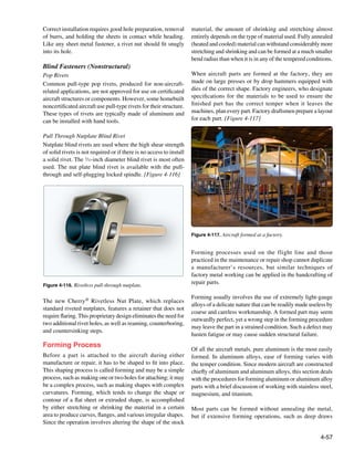
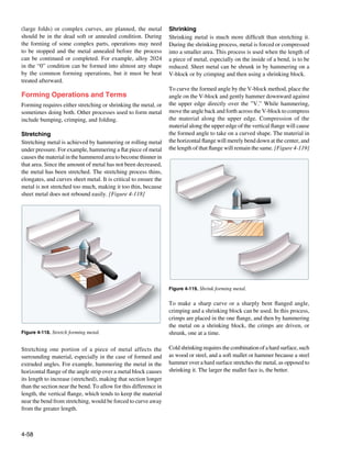
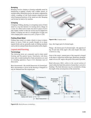
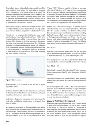
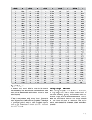
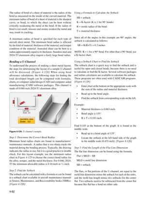
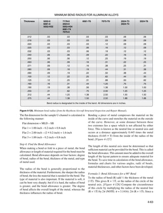
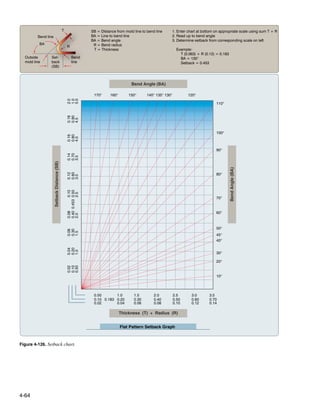

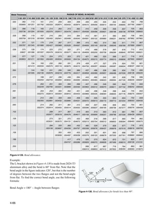
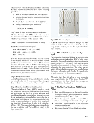
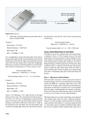
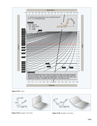
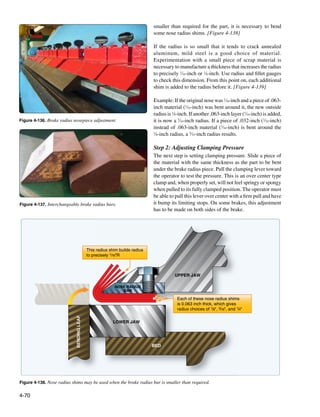
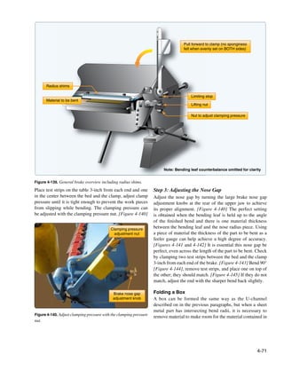
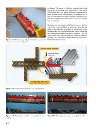
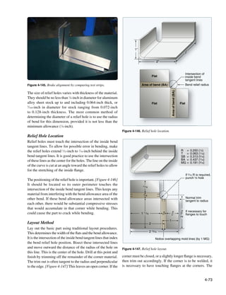
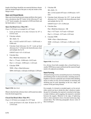
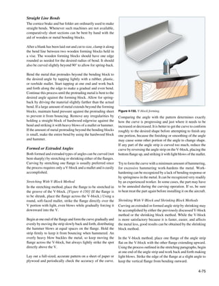
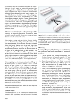
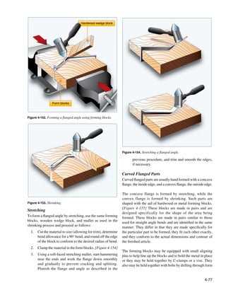
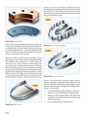
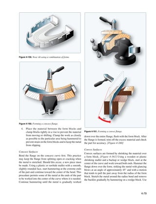
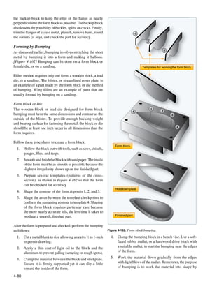
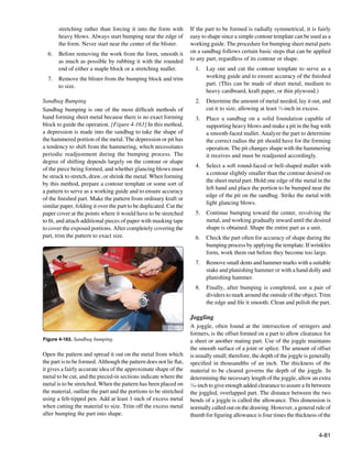
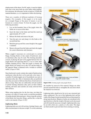
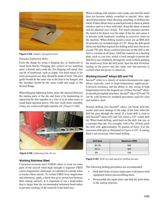
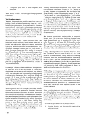
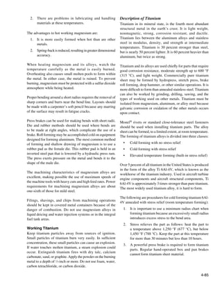
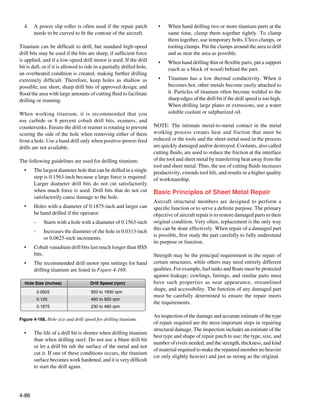
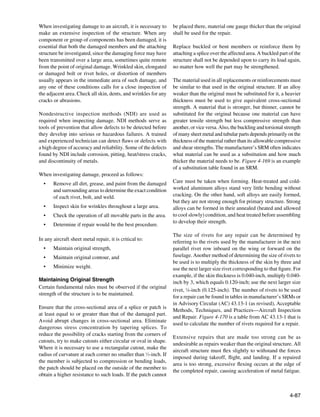
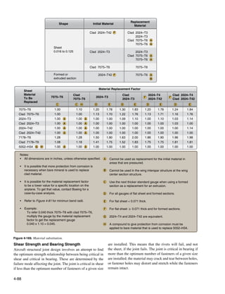
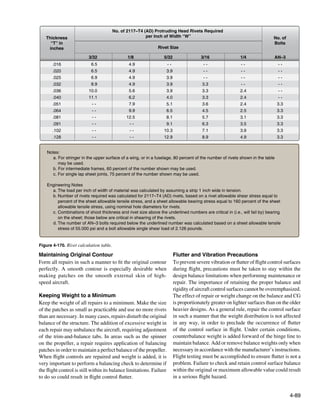
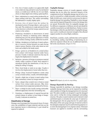
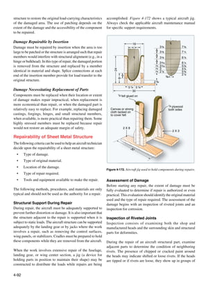
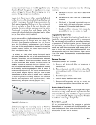
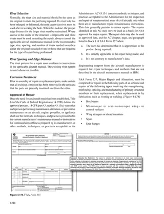
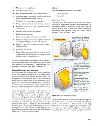
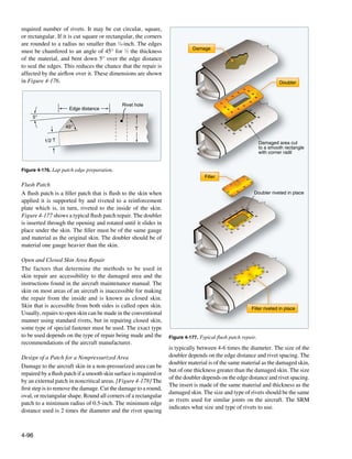
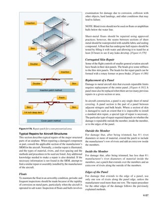
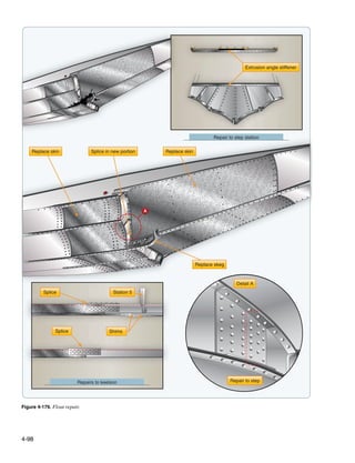
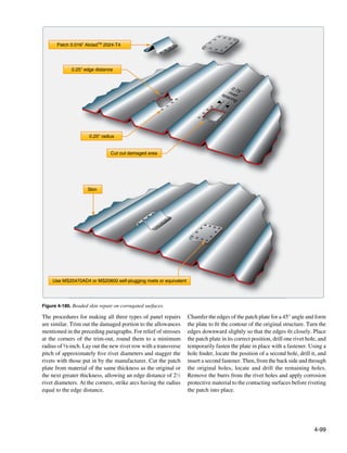
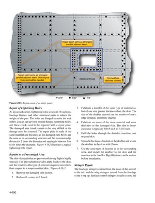
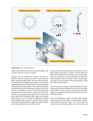
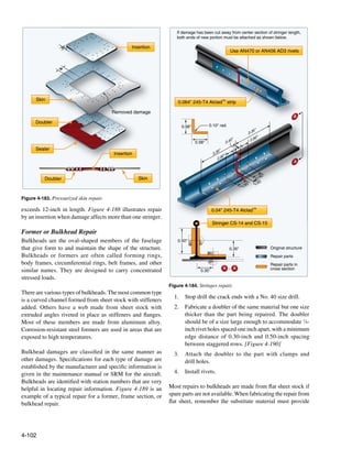
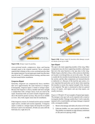
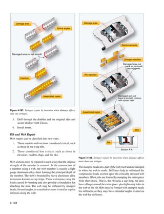
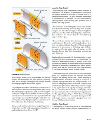
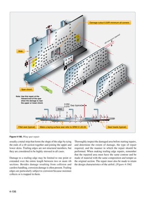
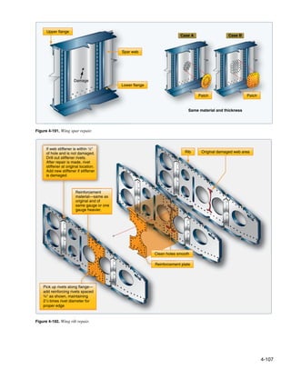
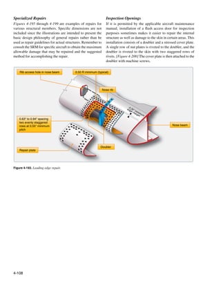
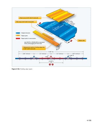
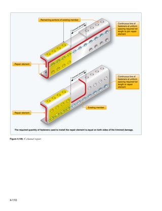
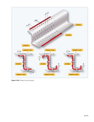
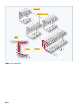
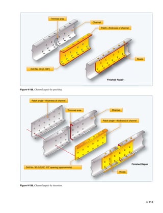
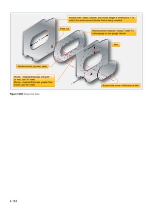
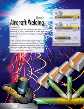
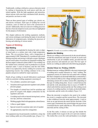
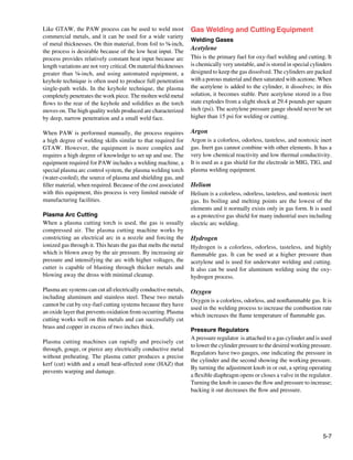
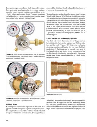
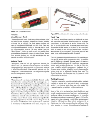
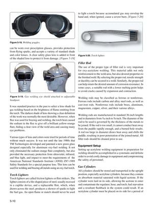
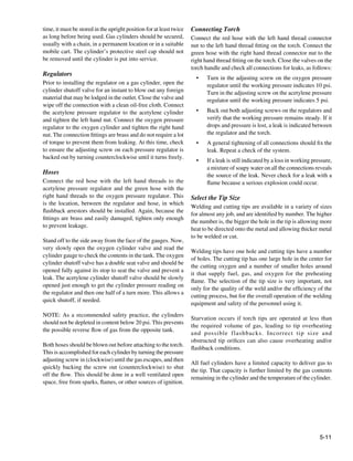
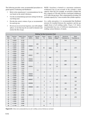
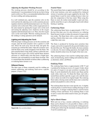
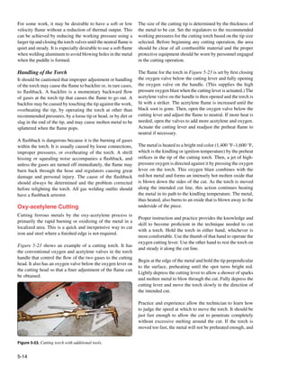
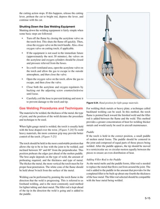
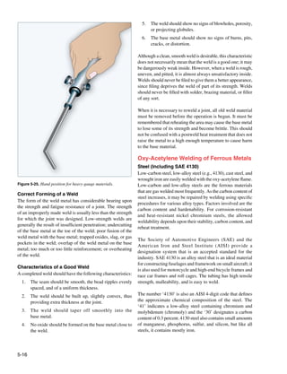
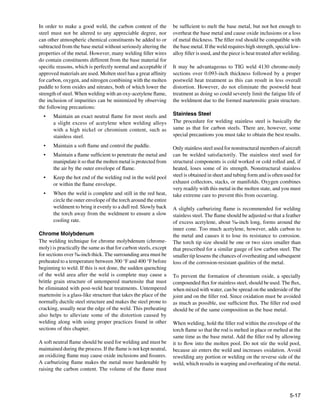
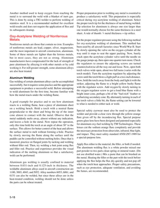
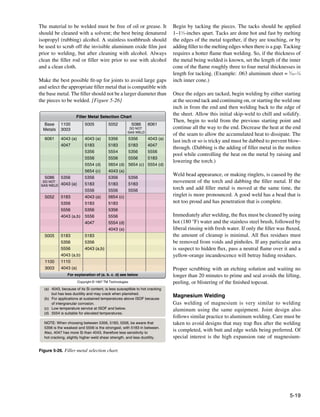
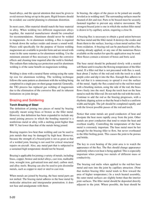
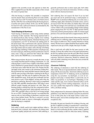
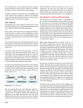
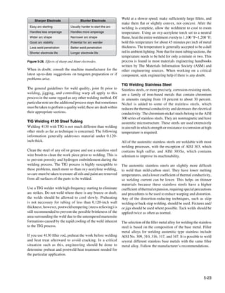
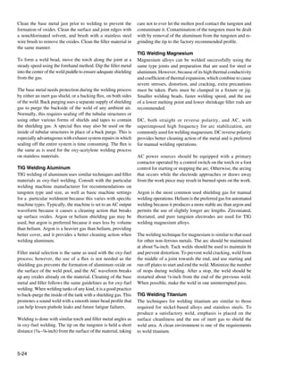
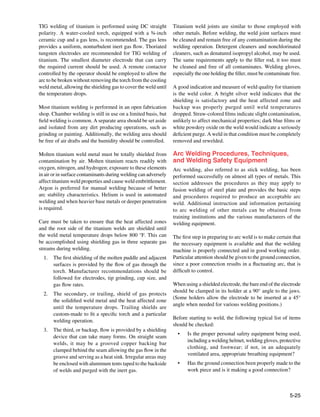
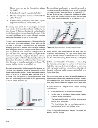
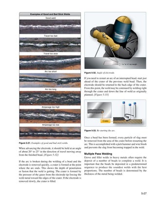
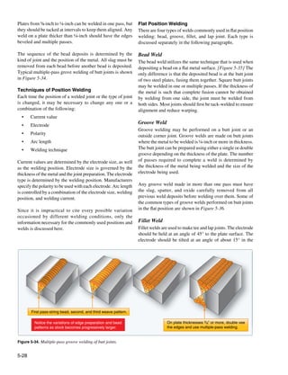
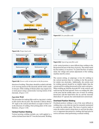
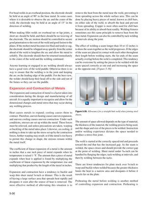
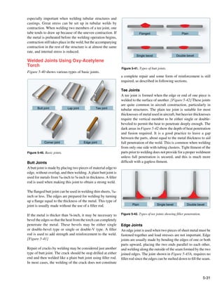
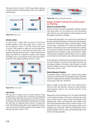
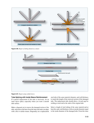
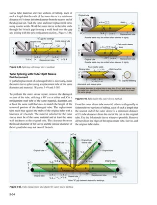
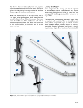
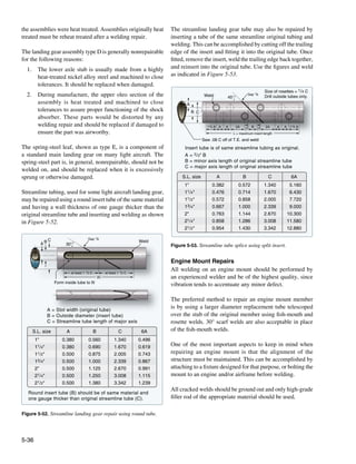

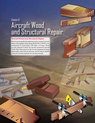
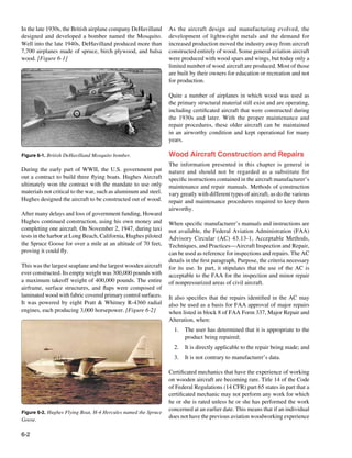
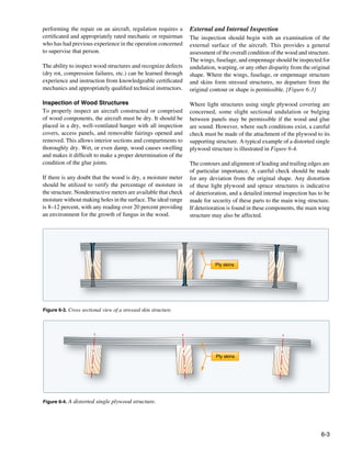
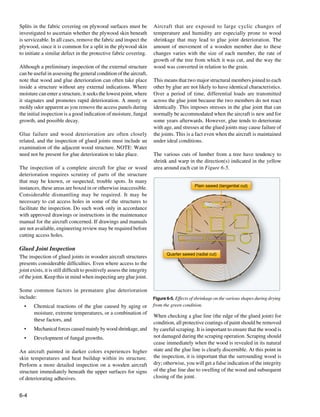
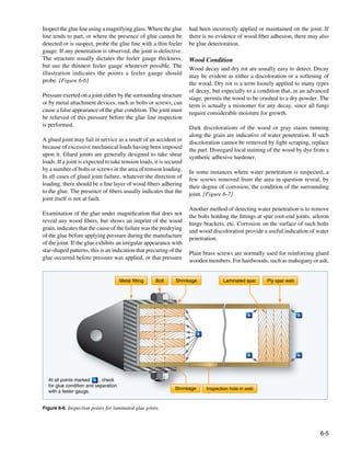
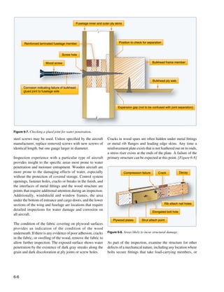
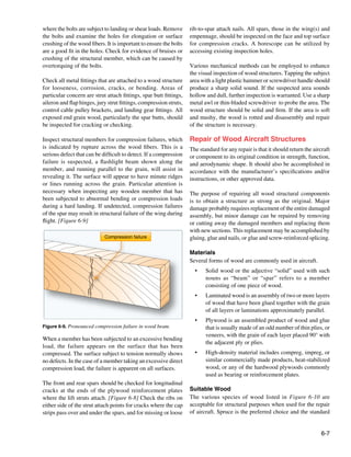
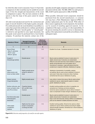
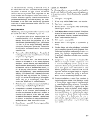
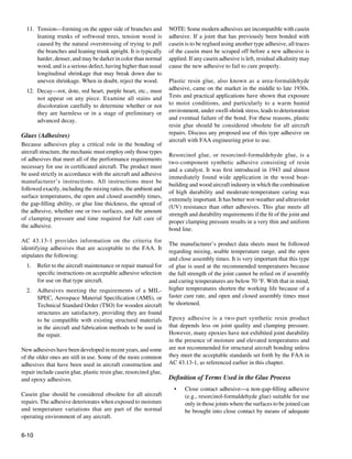
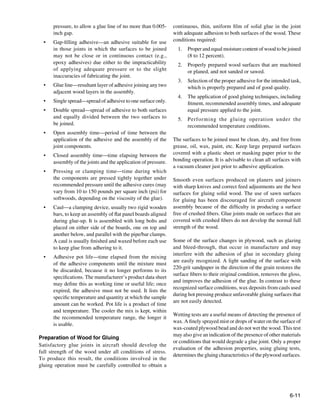
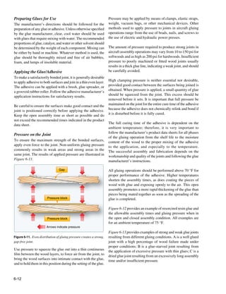
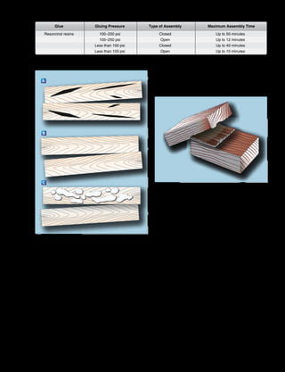
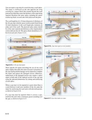
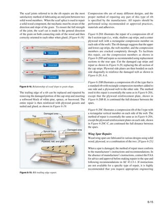
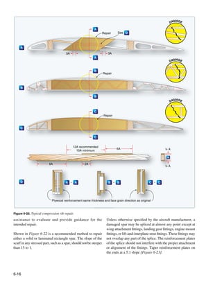
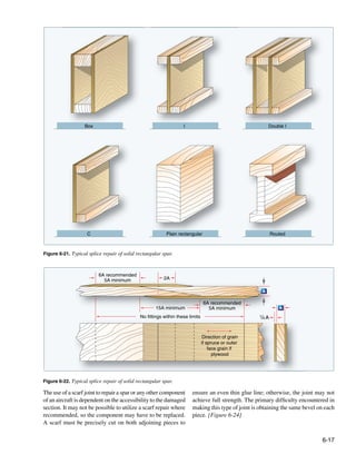
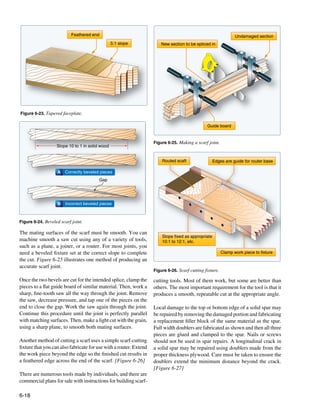

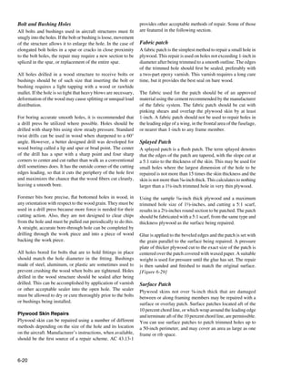
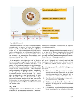
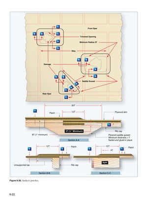
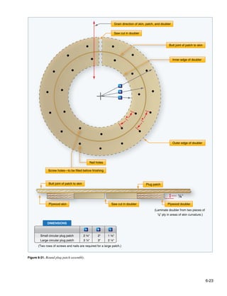
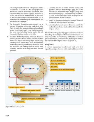
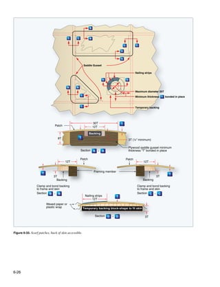
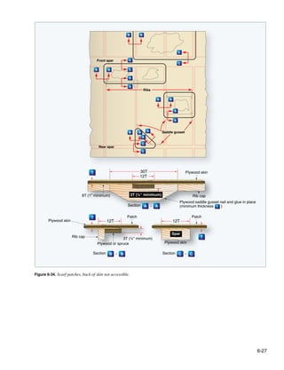

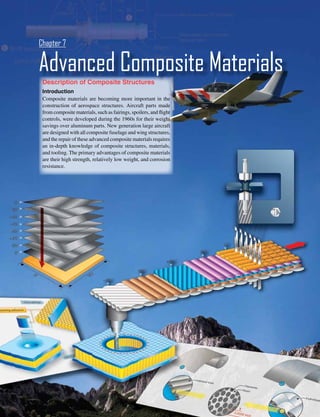
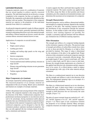
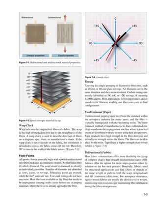
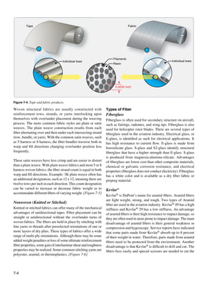
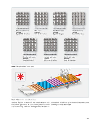
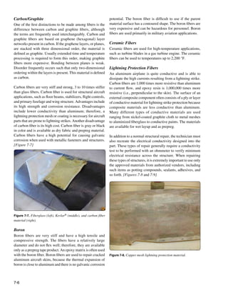
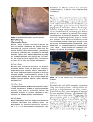
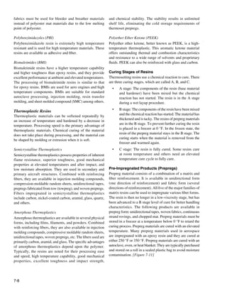
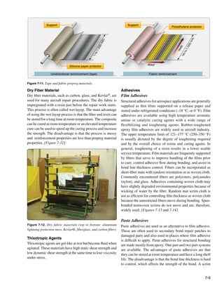
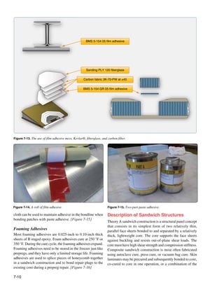
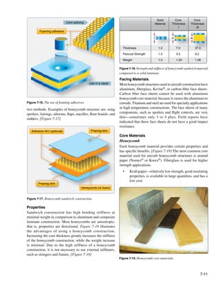
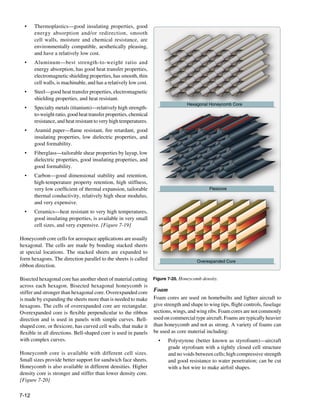
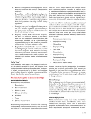
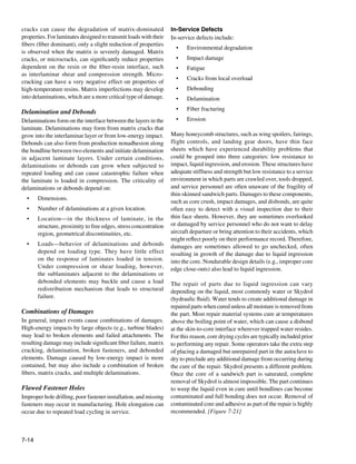
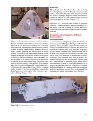
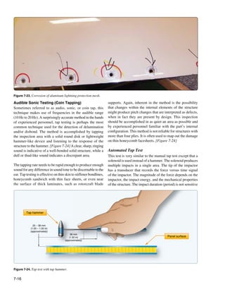
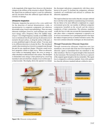
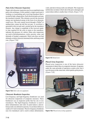
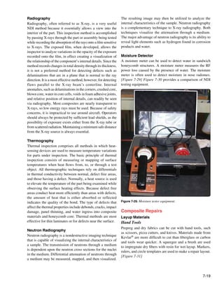
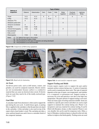
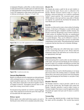
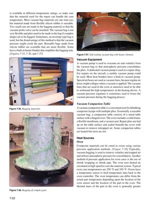
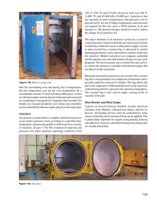
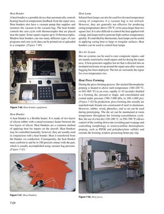
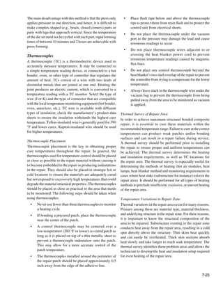
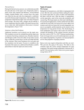
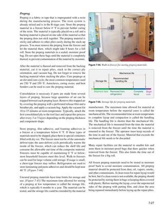
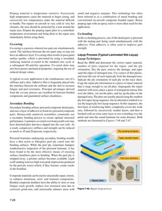
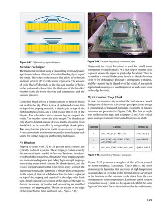
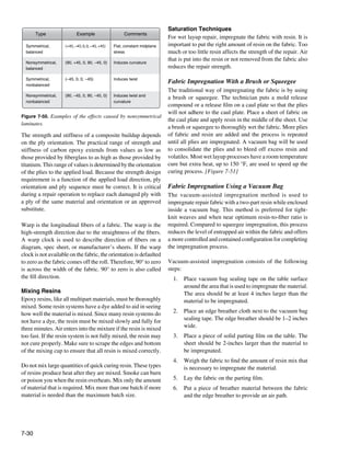
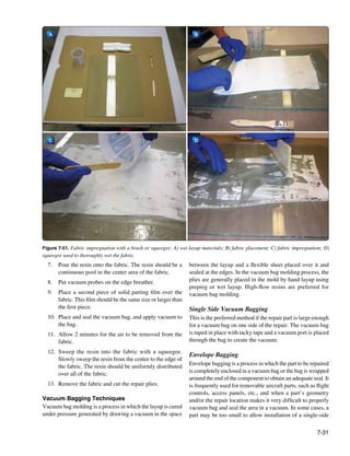
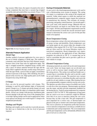
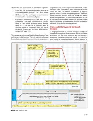
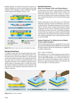
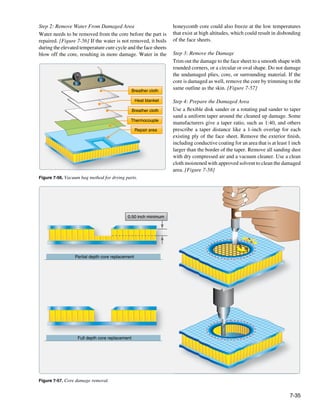
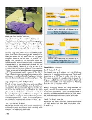
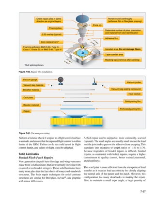
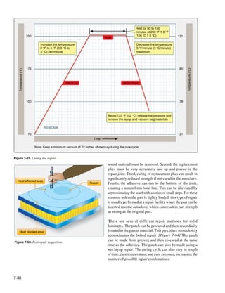
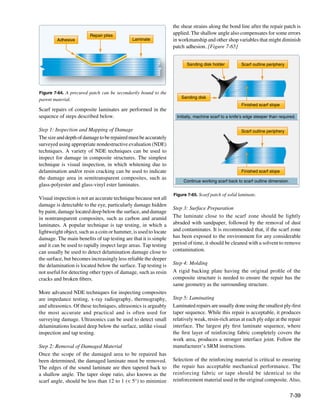
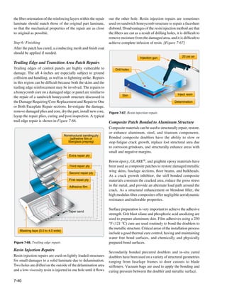
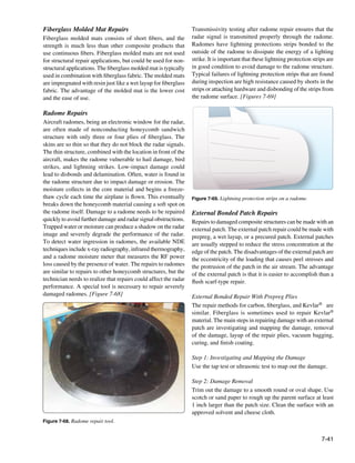
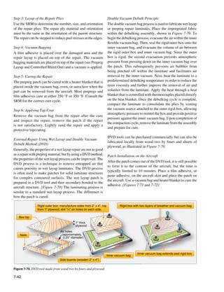
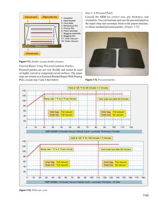
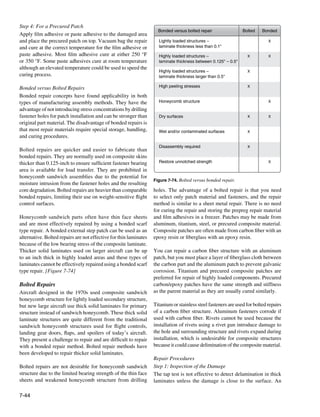
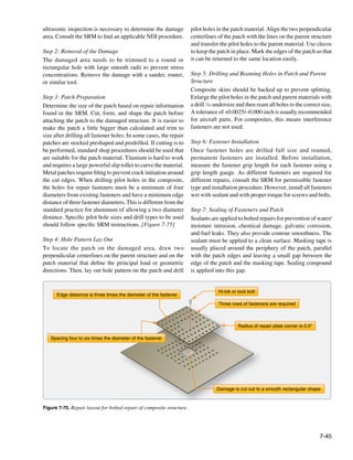
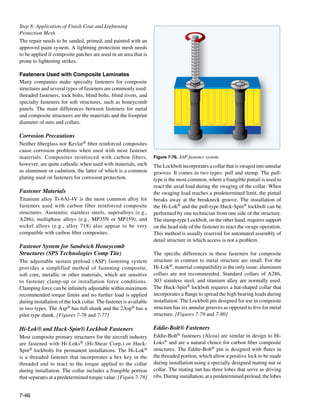
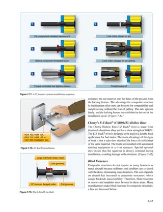
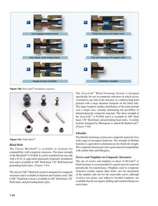
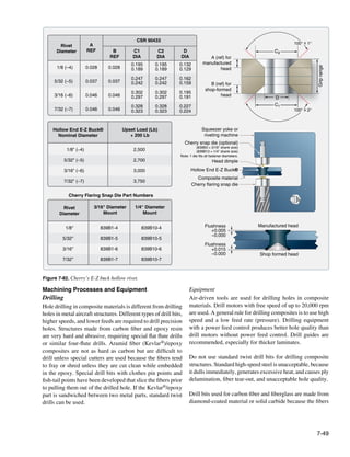
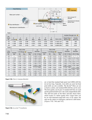
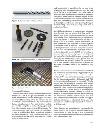
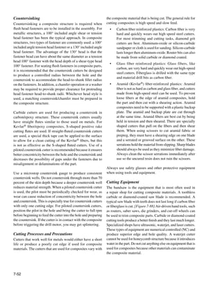
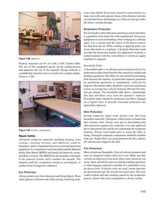
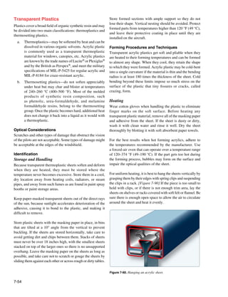
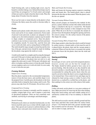
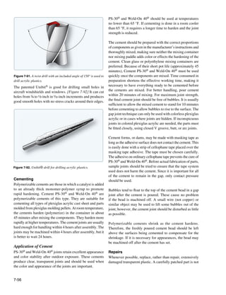
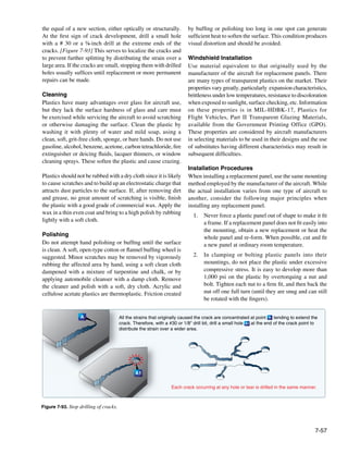
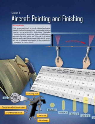
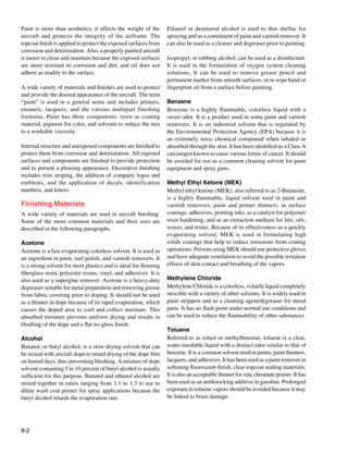
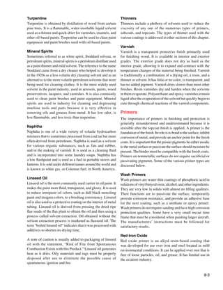
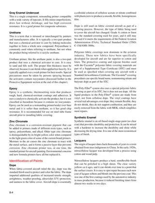
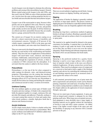
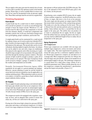
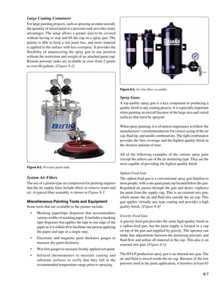
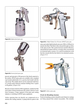
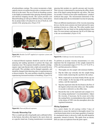
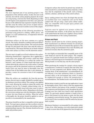
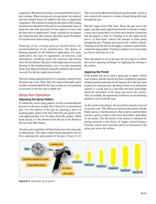
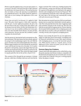
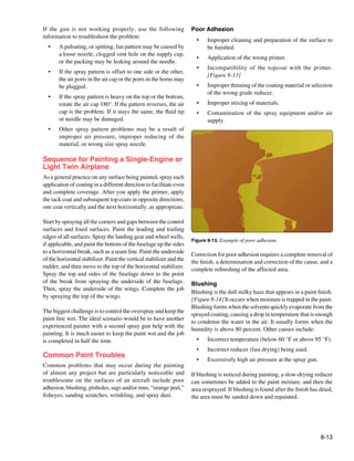
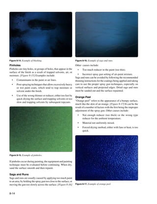
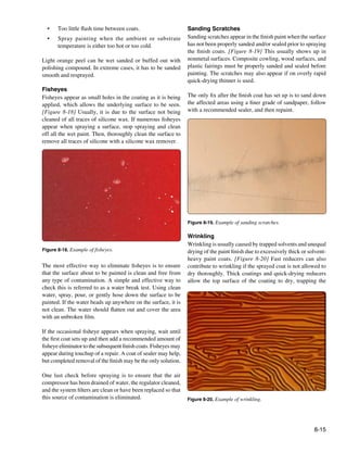
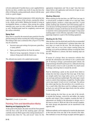
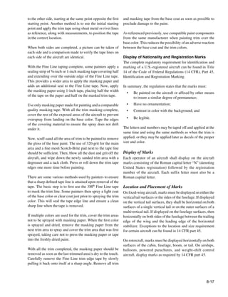
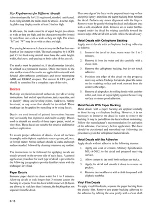
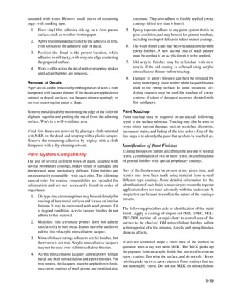
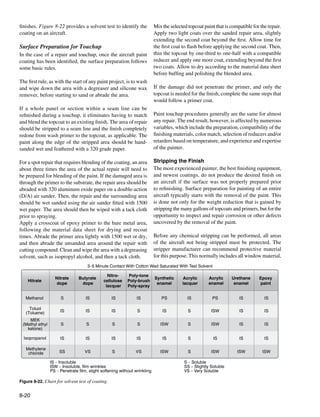
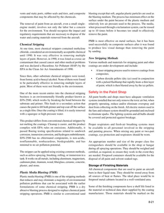
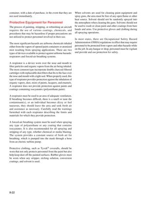
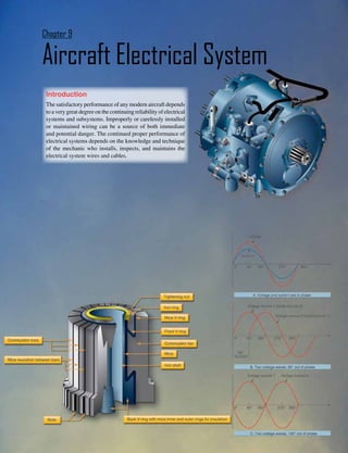
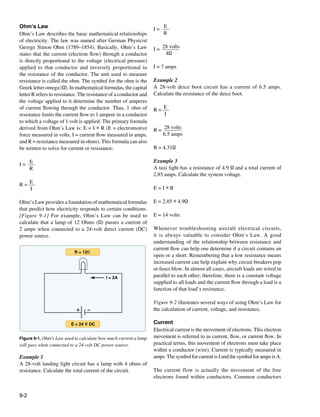
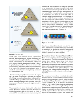
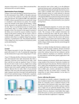
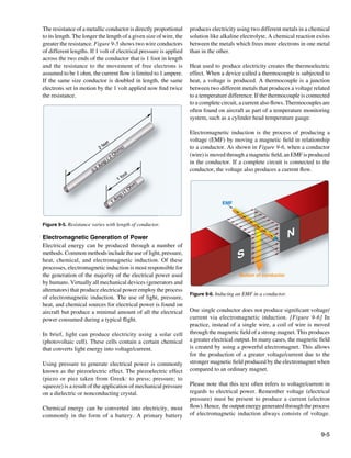
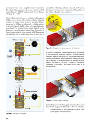
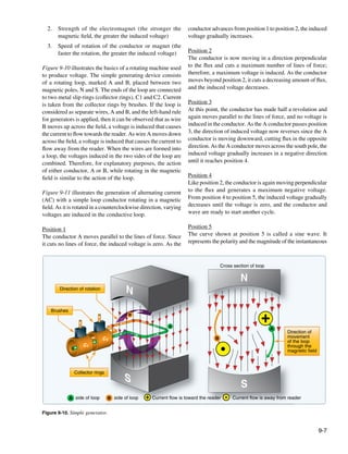
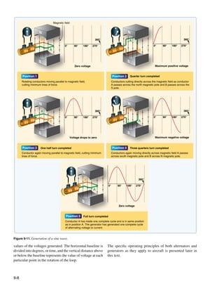
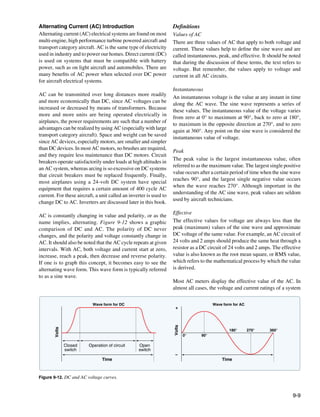
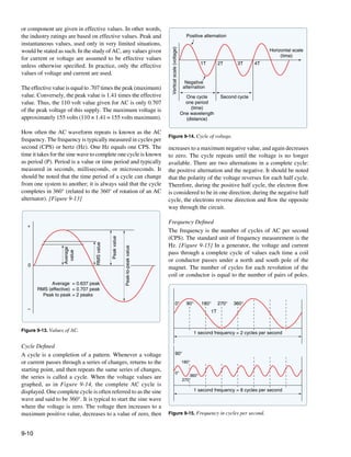
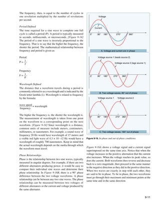
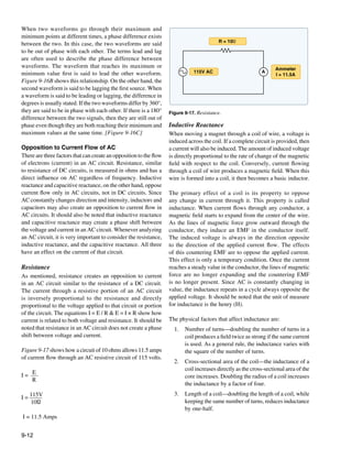
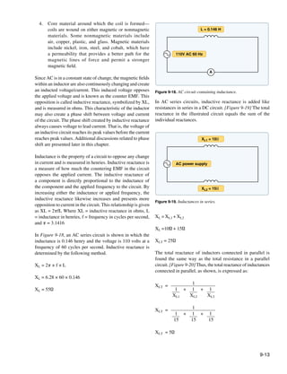
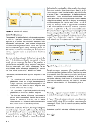
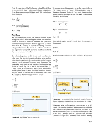
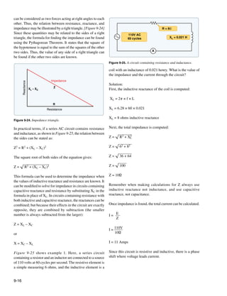
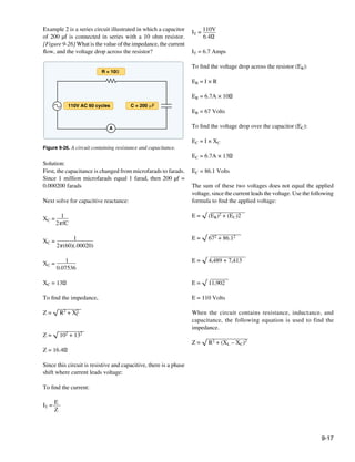
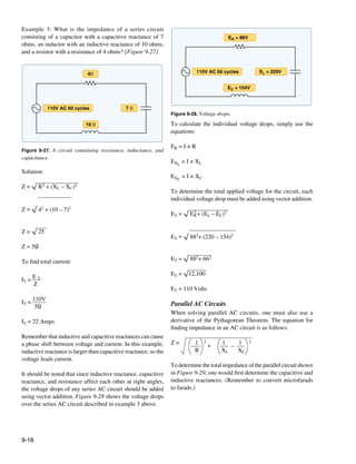

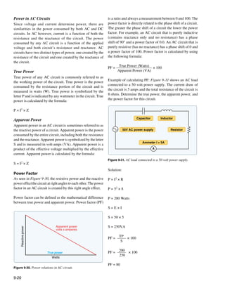
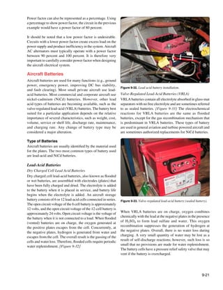
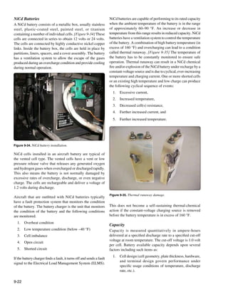
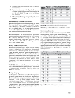
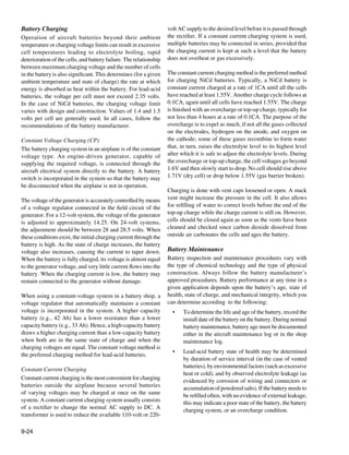
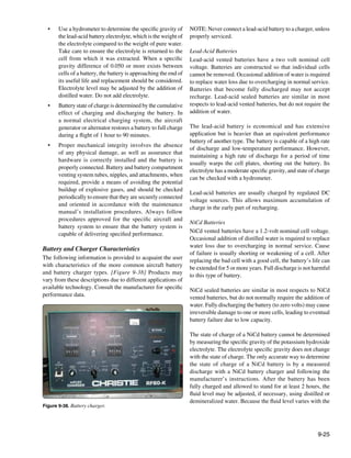
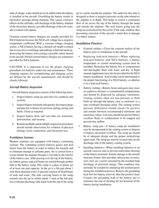
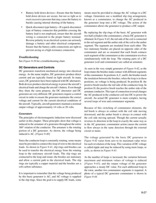
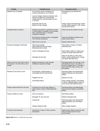
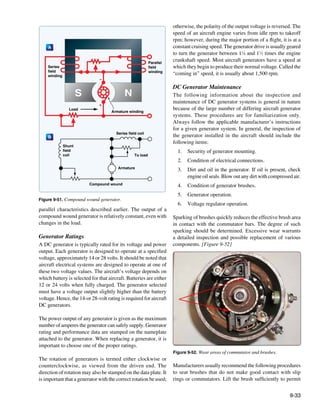
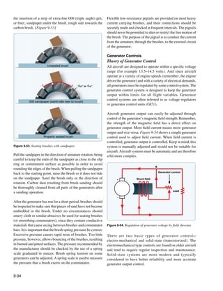
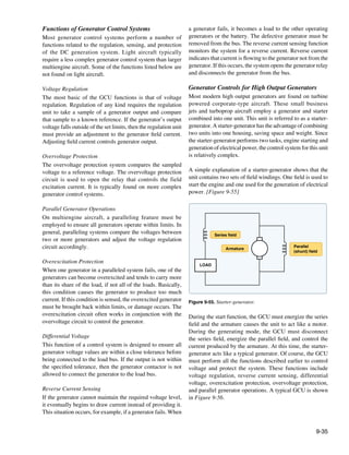
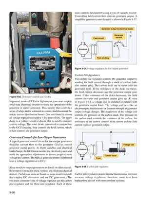
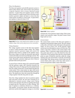
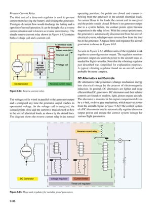
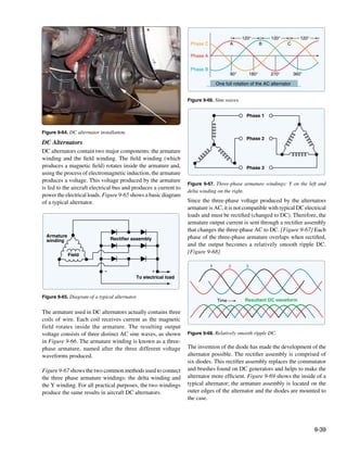
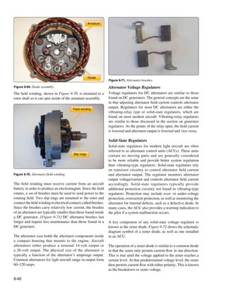
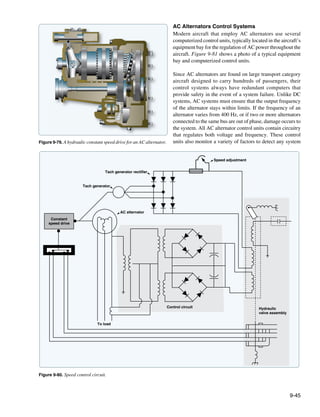
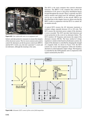
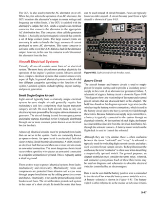
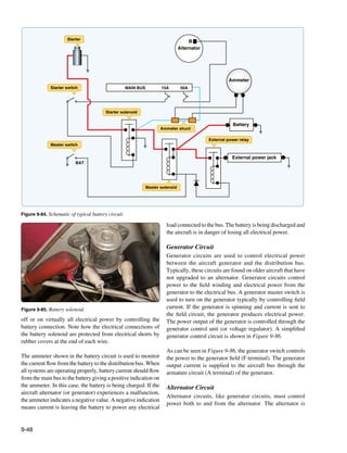
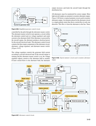
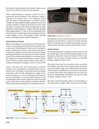
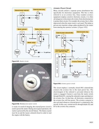
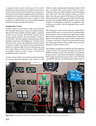
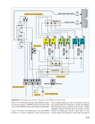
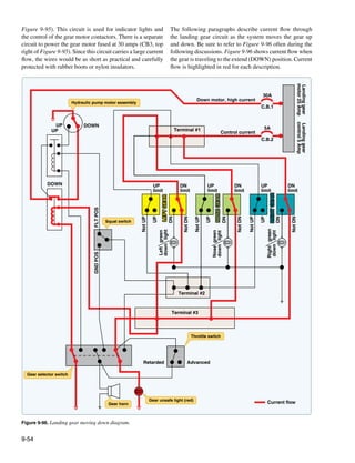
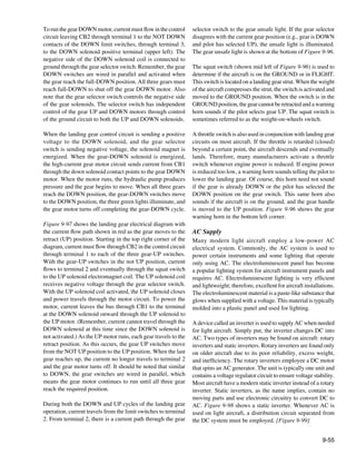
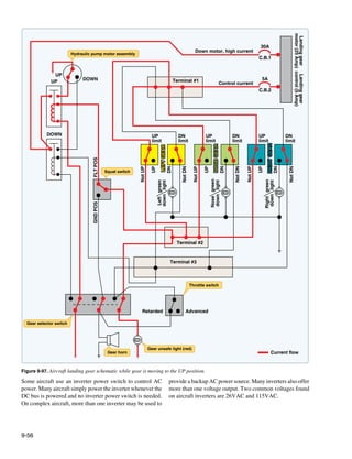
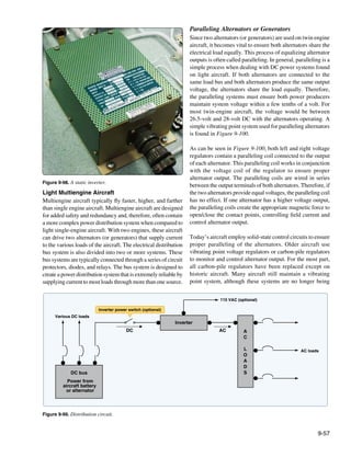
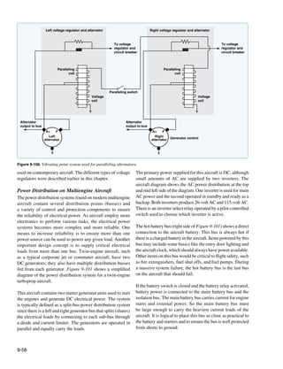
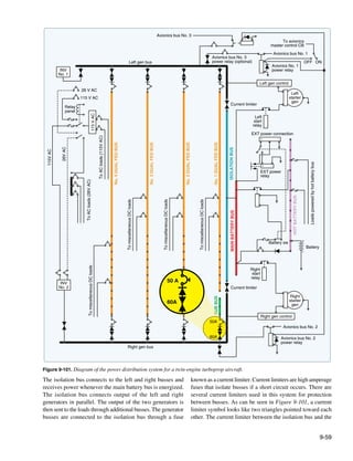
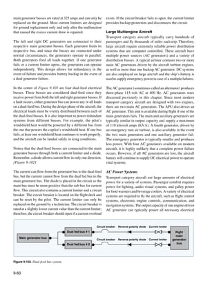
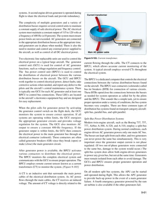
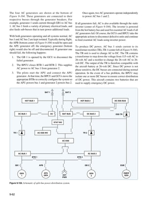
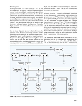
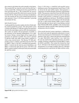
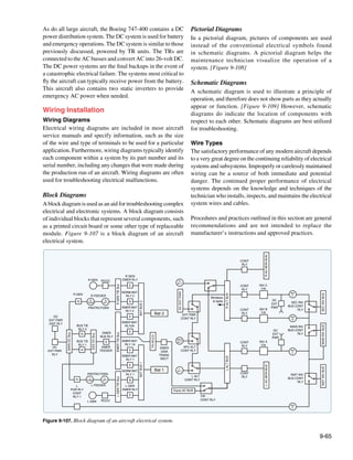
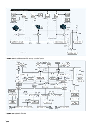
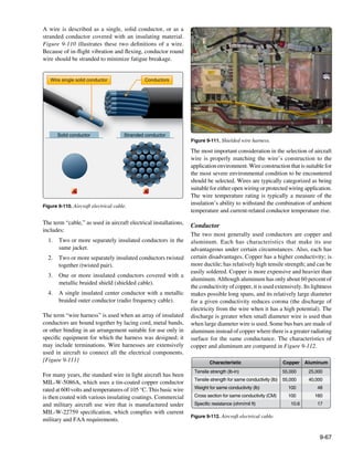
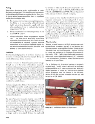
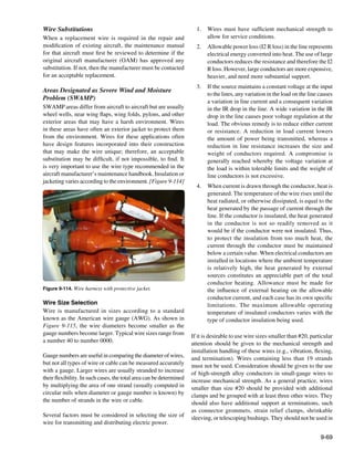
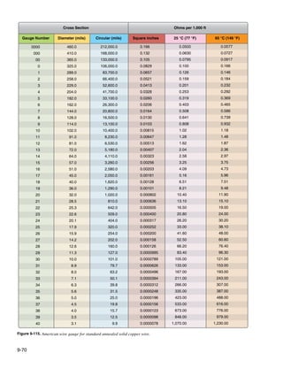
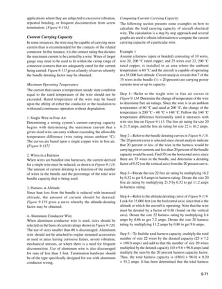
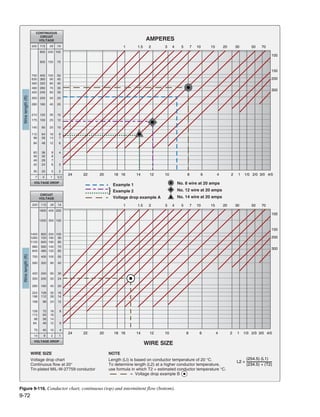
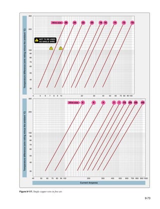
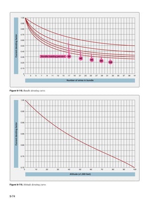
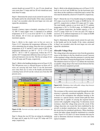
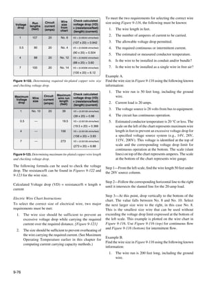
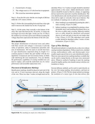
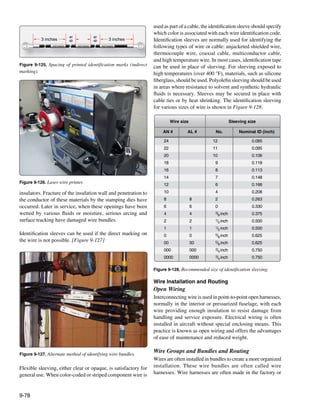
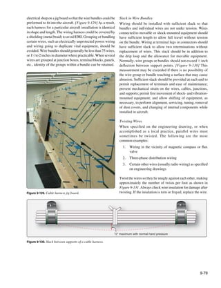
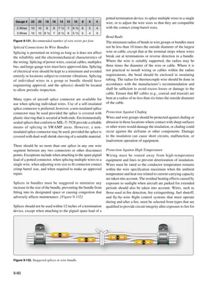
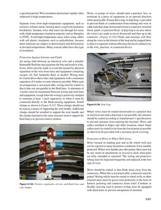
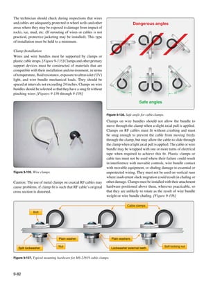
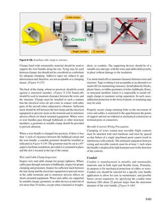
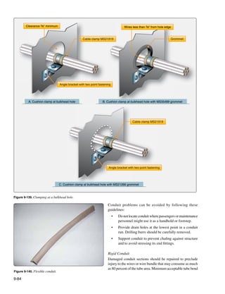
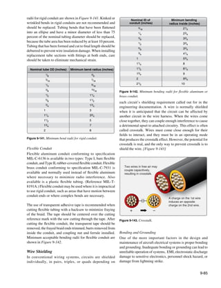
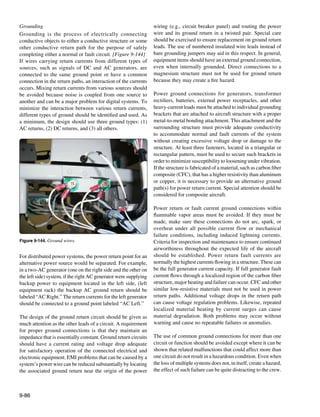
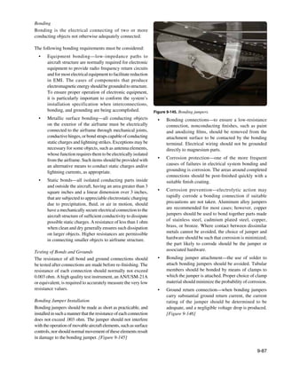
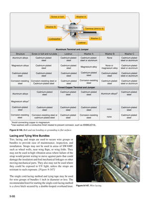
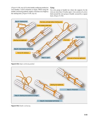
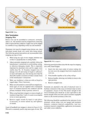
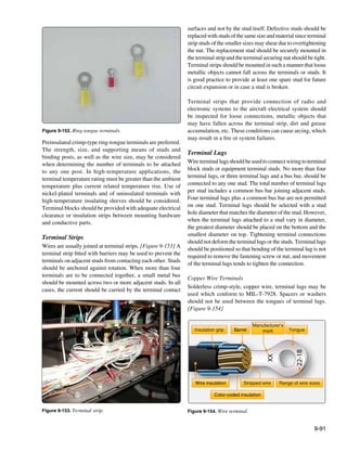
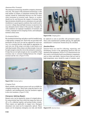
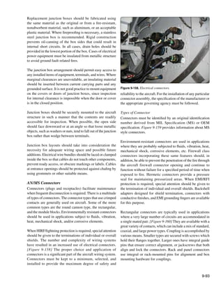
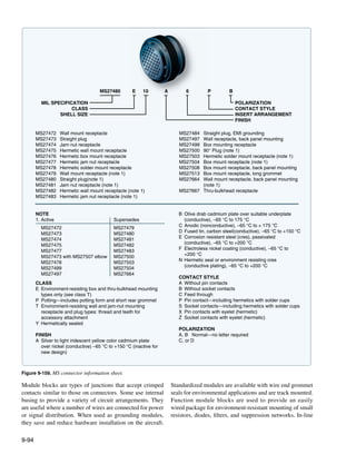
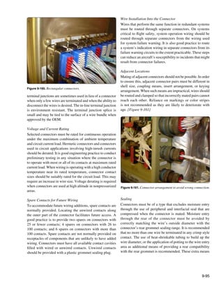
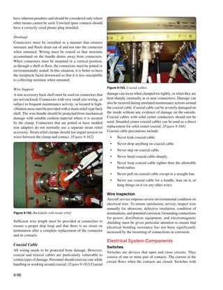
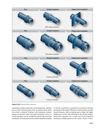
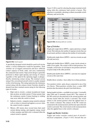
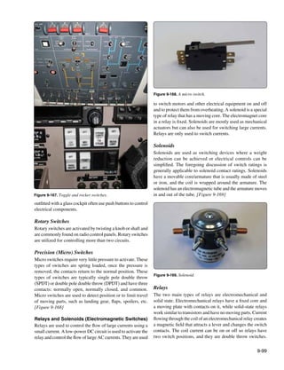
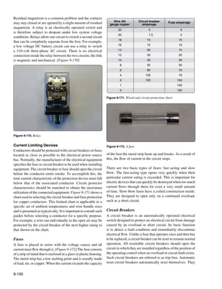
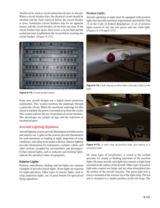
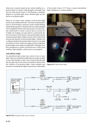
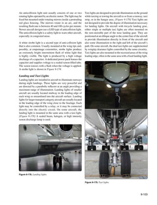
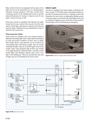


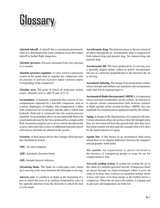
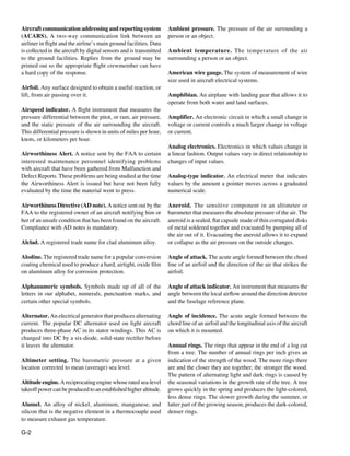
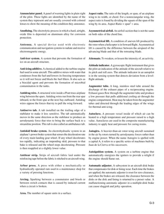
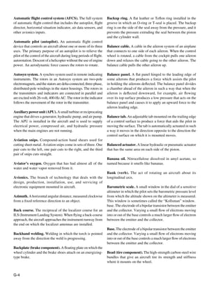
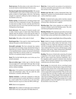
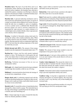
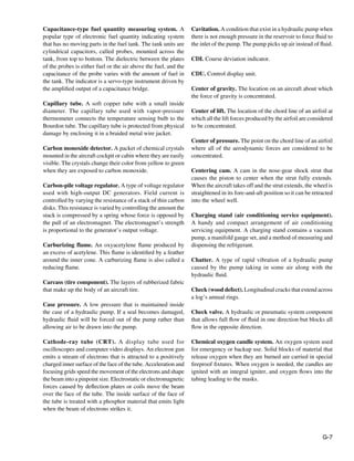
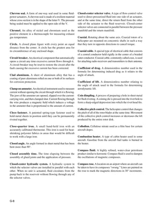
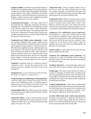
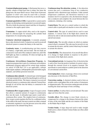
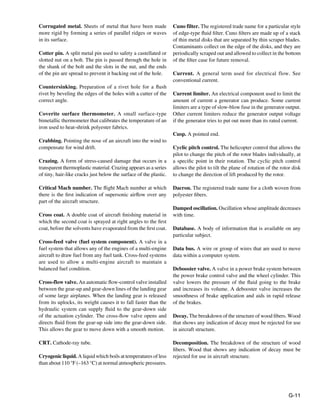
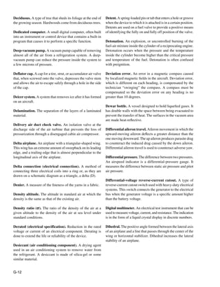
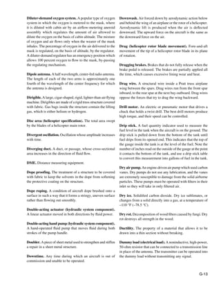
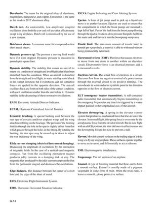
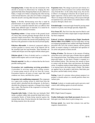
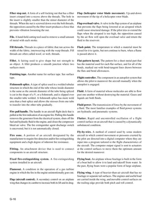
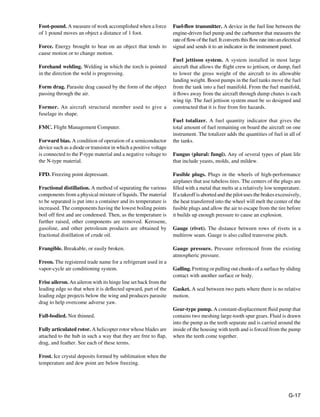
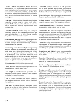
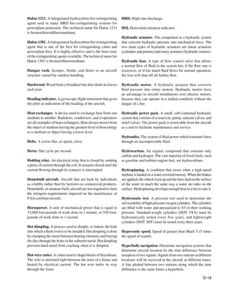
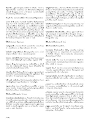
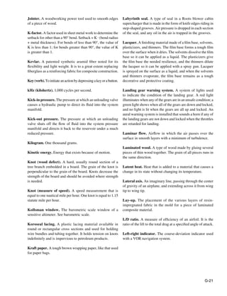
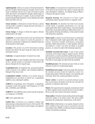
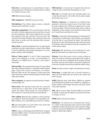
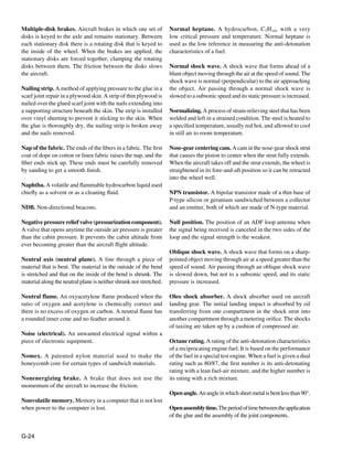
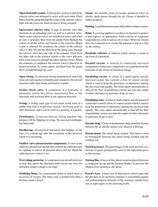
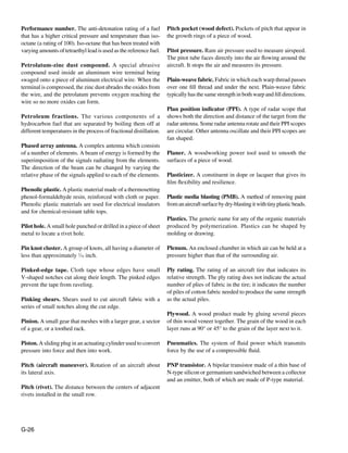
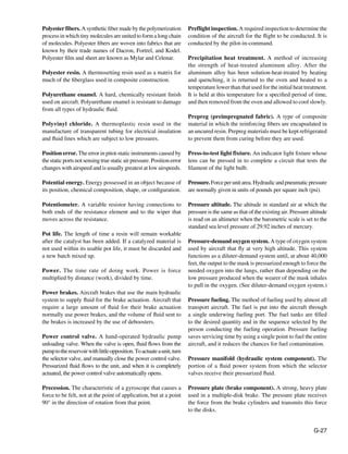
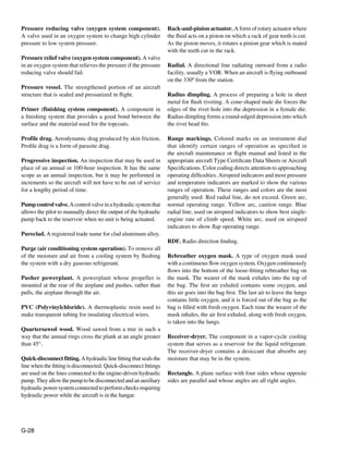
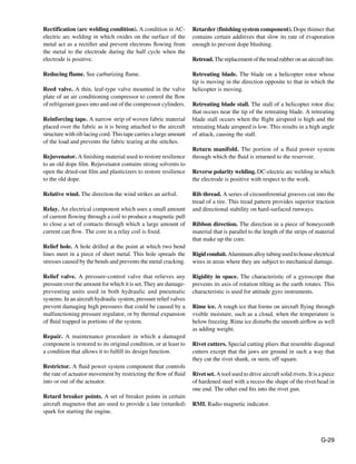
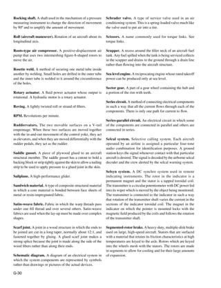
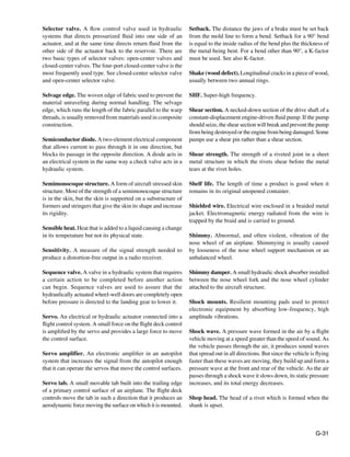
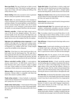
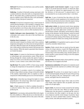
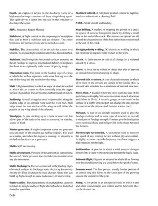
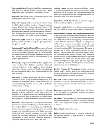
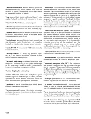
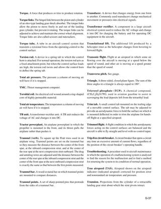
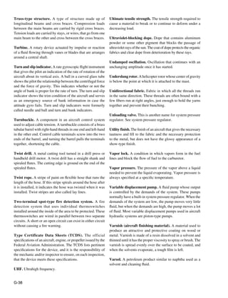
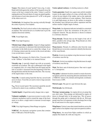
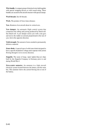

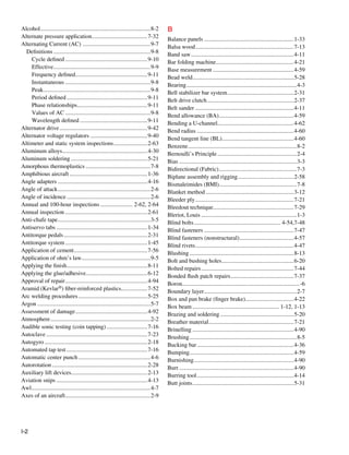
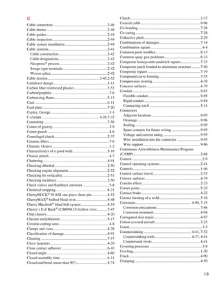
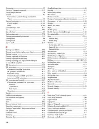
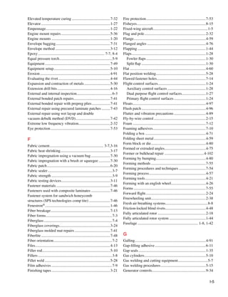
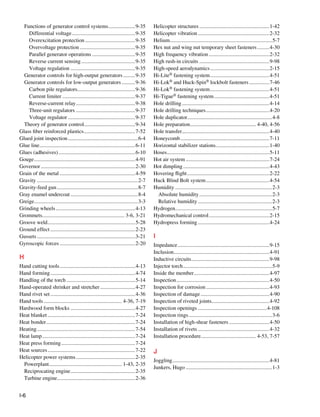
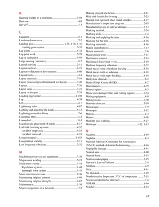
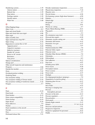
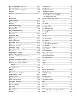
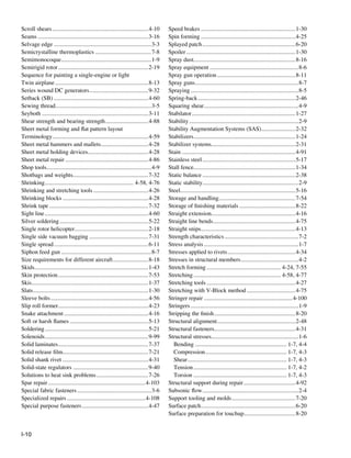
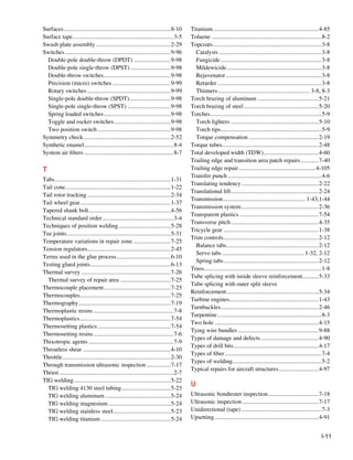
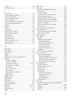
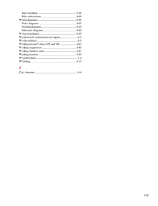


This document is the preface and table of contents for Volume 1 of the Aviation Maintenance Technician Handbook—Airframe. Volume 1 contains 17 chapters that cover topics such as aircraft structures, aerodynamics, aircraft assembly and rigging, aircraft fabric covering, aircraft metal structural repair, aircraft welding, advanced composite materials, and aircraft systems including electrical, hydraulic, pneumatic, fuel, instrumentation, and environmental control. The preface provides an introduction to the handbook and notes that it is intended to provide basic information and technical procedures for subjects relating to the airframe rating.


