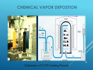
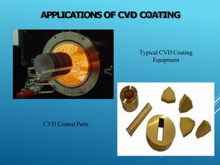
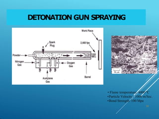
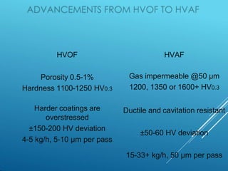
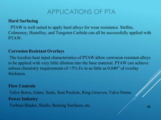
SlideShare a Scribd company logo
ADVANCEMENTS INSURFACE
ENGINEERING PROCESSES
1
S U R F A C E C O AT IN G
SURFACEENGINEERINGPROCESSES:TIMELINE
2
1908 Nitriding
1910 Wire Spray( M U Schoop Switzerland )
1923 Anodizing1924 Hard chrome Plating
1930 Physical Vapor deposition (PVD)
1955 Detonation Gun
1960 Plasma Spray ( Metco NY)
1965 Co2 Laser Cladding
1970 Chemical vapor deposition ( CVD) Widia Germany
1980 High Velocity Oxy Fuel ( HVOF)
1990 Cold Spray ( Russia to NCMS)
2000 High Velocity Air Fuel ( HVAF)
2005 Fibre laser cladding
2003 Cold spray commercial equipment
2017 EHLV(High speed laser spray cladding )
GAS NITRIDING
3
GAS NITRIDINGPROCESS
4
 Gas Nitriding
 In gas Nitriding the donor is a nitrogen rich gas,
usually ammonia (NH3),
 When ammonia comes into contact with the heated work piece it
dissociates into nitrogen and hydrogen.
 The nitrogen then diffuses onto the surface of the material creating a
nitride layer. This process has existed for nearly a century
 Recent developments have led to a process that can be accurately
controlled. The thickness and phase constitution of the resulting
Nitriding layers can be selected and the process optimized for the
particular properties required.
PLASMA NITRIDING
5
Schematic Representation of Plasma Nitriding
PLASMA NITRIDINGPROCESS
 Plasma Nitriding, also known as ion
Nitriding, plasma ion Nitriding or glow-discharge
Nitriding, is an industrial surface hardening
treatment for metallic materials.
 In plasma Nitriding, the reactivity of the Nitriding
media is due to the gas in ionized state. In this
technique intense electric fields are used to
generate ionized molecules of the gas around the
surface to be nitrided. Such highly active gas with
ionized molecules is called plasma, naming the
technique. The gas used for plasma Nitriding is
usually pure nitrogen, since no spontaneous
decomposition is needed (as is the case of gas
Nitriding with ammonia).
6
APPLICATIONS OF NITRIDING
7
Plasma Ion Nitriding on Gears
Gas Nitride coating on Screws AND GEARS
HARDCHROME PLATING
8
HARD CHROME PLATING
• Chrome Discovered 1798,, first successful electrolytic
• plating 1856, commercial utilization late 1920’s
•
Advantages
–Resists most chemicals, oxygen, and
moisture in air
– Does not tend to seize,, gall,, or cold weld
– Hard surface typical 62 Rc, 0.003”--0..015”
typical thickness
– Simple technology
– Excellent wear resistance
– Historically relatively inexpensive
ISSUES WITH HARD CHROME PLATING
– The process produces large amounts of
hydrogengas in the gas bubbles burst
throwing hexavalentchrome solution into the
air as fine mist.
– Hexavalentchrome is a know carcinogen.
– The process produces large volumes of toxic
waste..
– EPA and OSHA have mandated more
stringent stack emission levels and lowering
of permissible exposure limitsfor workers.
– T
h
i
s results in increased costs and business
risks..
ENP
(ELECTROLESSNICKELPLATING)
11
ADVANTAGES OF ENP
12
 Even coating on parts surface can be achieved.
 No sophisticated jigs or racks are required.
 There is flexibility in plating volume and thickness.
 The process can plate recesses and blind holes with stable
thickness.
 Chemical replenishment can be monitored automatically.
 Complex filtration method is not required
 Matte, semi-bright or bright finishes can be obtained.
APPLICATIONOF ENPCOATING
14
ENP Coated Bolts
Wheel Rims ENP Coated
15
 PVD is characterized by a process in which the material
goes from a condensed phase to a vapor phase and then
back to a thin film condensed phase. The most common
PVD processes
are sputtering and evaporation. PVD is used in the
manufacture of items which require thin films for mechanical,
optical, chemical or electronic functions. Examples include
semiconductor devices such as thin film solar panels,
aluminized PET film for food packaging and balloons, and
titanium nitride coated cutting tools for metalworking. Besides
PVD tools for fabrication, special smaller tools (mainly for
scientific purposes) have been developed.
 The source material is unavoidably also deposited on
most other surfaces interior to the vacuum chamber,
including the fixturing used to hold the part
16
17
PVD Coating on Drill Bits & Ornaments
18
Schematic of CVD Coating Process
CVD (CHEMICAL VAPOR DEPOSITION)
19
 Chemical vapor deposition (CVD) is
a chemical process used to produce high
quality, high-performance, solid materials.
The process is often used in
the semiconductor industry to produce thin
films.
 In typical CVD, the wafer (substrate) is
exposed to one or more volatile precursors,
which react and/or decompose on the substrate
surface to produce the desired
deposit. Frequently, volatile by-products are
also produced, which are removed by gas
flow through the reaction chamber.
APPLICATIONSOF CVD COATING
20
Typical CVD Coating
Equipment
CVD Coated Parts
CVD V/SPVD
21
22
HP/HVOF
HVAF
Axial
plasma
Wire
spray
Metco
2E
Cold spray
NCMS
Laser cladding
Cold spray
commercial guns
wire
s
23
xtausraxx
Various surface Modification
processes
Particle velocity V ~
800- 1200m/sec
Spray dist 6-15 inches –
No
heat transfer to base
D
-- =
3.5
d
Gun-
Flsme/Plasma/HV
OF
Flame Temp
3000-
15000*C
Heated
particles
propelled
Concept and
Schematic of
THERMAL SPRAY
Grit blasted surface
Layer by layer coating builds up
26
Chemical
Composition
Manufacture Method
Particle Shape
Particle Size
Distribution Hall Flow
Apparent Density
Liquid- or Gas-
Fuel Spray Gun
Choice Fuel
Used
Spray
Parameter
Kinetic Energy
Thermal
INPUT MATL/POWDER SPRAY PROCESS / GUN COATING
PROPERTIES
Wear Resistance
Corrosion
Resistance Phase
Composition Bond
strength Hardness
Porosity
Deposition Efficiency
PLASMA SPRAYING
• Most versatile process in
terms of range of coatings
•plasma temperature: up to 15000 ºC.
• virtually all existing materials
including ceramics. Flame spray 32
57
0-
500m/sec
DETONATION GUN SPRAYING
• Flame temperature: 4000 ºC
•Particle Velocity : 1000 m/Sec.
•Bond Strength: 100 Mpa
28
HIGH-VELOCITYOXY FUELSPRAYING (HVOF)
29
HVOF
Porosity 0.5-1%
Hardness 1100-1250 HV0.3
Harder coatings are
overstressed
±150-200 HV deviation
4-5 kg/h, 5-10 µm per pass
HVAF
Gas impermeable @50 µm
1200, 1350 or 1600+ HV0.3
Ductile and cavitation resistant
±50-60 HV deviation
15-33+ kg/h, 50 µm per pass
HVAF
Jet Kote
Kermetico C6, C7
1700-
2100 °C
DJ 2600
JP 5000
2982 °C
2982 °C
Opt Tc + Axial
↓
Opt heating
Long nozzle
↓
Opt velocity
THE RESULT
kermetico.com jrienecker@kermetico.com
Gu
n
Hardness,
HV300
Poro
-sity,
%
Fracture
Tough-
ness
K1C
Ratio
W2C
to
WC
AK 1,326 ± 98 0.3
5.97
±0.7
0
JP
1,289 ±
108
0.6
4.87
±0.6
0.12
JK
1,047 ±
112
1.7
3.01
±0.6
0.7
Source: Wear and corrosion performance of
WC-10Co-4Cr coatings deposited by different
HVOF and HVAF spraying processes
Qun Wang etc., Hunan University, 2013
JP 5000
AK7
Jet Kote
EROSIONRATEVS. AN ATTACK ANGLE:
WC-10CO-4CR HVAF COATINGS PERFORM AS A
DUCTILEMATERIAL
Midwest Thermal Spray (MI, USA)
0.000
0.050
0.100
0.150
0.200
0.250
0.300
AK06-HVAF: WC-Co-Cr HVOF MTS: WC-Co-Cr SHS8000, fused
Volume
loss,
mm3/min
Dry erosion rate of hard coatings
Angle 30 deg. Angle 90 deg.
UNIFORMITYOF HVAF COATING PROPERTIES:
HARDNESS OF HVOF AND KERMETICO HVAF WC-10CO-4CR COATINGS
(SCHLUMBERGER, UK)
kermetico.com jrienecker@kermetico.com
HVAF
OF
Relative standard
deviation, %
HVAF: 3.9 %
HVOF: 15.7-17.8%
KERMETICOHVAF:
YOUR CHOICE OF COST AND QUALITY
kermetico.com jrienecker@kermetico.com
HVAF-E (Economy) – meets HVOF specs
HVAF-B (Balanced) – exceeds HVOF specs
HVAF-U (Ultra) – Coatings beyond the limits
HV spraying = deposition + blasting
Well bonded particles will stay, poor bonded will go away
Higher velocity => more blasting => ↑quality ↑cost
36
Spray Particle Temperature Vs. Wc & W2C Phase CompositionB
HVAF working zone
(1600-1800 C )
HVAF COATINGS PERFORM BETTER
THAN HVOF
HVAF tungsten carbide coatings
are harder and stronger than
HVOF ones, yet they are ductile.
These are the reasons why they
resist wear and cavitation
combined. 37
Suspension HVOF-spraying
39
Power and aero turbine areas where coatings
are applied. Cold zone and Hot zone and
abradables
SEVERESERVICEAPPLICATIONS
40
Plug Valve TC Coating Control Valve Stem-Stellite 6 Coating
Ball Valve TC Coating Mud Rotor TC Coating & Super Polish
APPLICATIONSOF HVOF &HVAF INCOATING OF
FRANCIS T
U
R
B
I
N
EHEAD COVER
kermetico.com jrienecker@kermetico.com
WC-Co-Cr
1 mm thick
Conveyor Screws
ROTOR SHAFT
REPAIR –
CHROME CARBIDE
Repair of turbine casing
Applications of TC Coating in Power Turbines
PUMPAND VALVE APPLICATIONS
P u m p a n d v a l v e a p p l i c a t i o n s
C a g e c a r b i d e c o a t e d K n i f e G a t e v a l v e b o d y c a r b i d e
c o a t e d
I m p e l l e r c e r a m i c c o a t e d
S l e e v e c e r a m i c c o a t e d &
G r o u n d
C e r a m i c c o a t e d s l e e v e s
F o r F o o d i n d u s t r y
44
H a r d f a c e d p u m p s l e e v e
BRIDLE ROLL
CARBID
E COATING
Application of HVOF Coating- Steel Mill CRM Roll
46
Spray Particle Temperature Vs. Wc & W2C Phase CompositionB
HVAF working zone
(1600-1800 C )
47
Compressed
gas
Powder
feeder
Substrate
The gas dynamic cold spray coating is based on the projection of solid powder at
high velocity.
De Laval Nozzle
Principle of cold spray
1. A compressed gas is heated before entering in a DE
Laval Nozzle.
2. The gas is accelerated in the nozzle.
3. Powder is injected in the gas stream and accelerated as
well.
4. The powder reaches velocity up to 1200 m/s.
5. The powder is plastically deformed and the coating is
building up.
COLD SPRAYING
• Gas temperature: under the
phase transition temperature ~ 800,1000C
• sprayed materials: pure Al, Zn, Cu, Ni
Alloys : NiCr, Cr- Carbide/NiCr 49
Assadi et al., Bonding mechanismin cold gas spraying, Acta
Materialia, 51, 4379-4394, 2003
Bonding mechanism
T. Schmidt et al., From Particle Acceleration to Impact and Bonding in Cold Spraying, Journal of
Thermal Spray Technology, 18, 5-6, 794-808, 2009
Typical surface around the critical velocity
Q. Blochet, Influence of substrate surface roughness on cold-sprayed coating-substrate bond strength in aluminum-
based systems, PhD Thesis, Mines ParisTech, 2015
51
Cold spray advantages and limitations
Advantages:
• No powder melting
No phase change
No grain growth
Low heating of the substrate
• No significant impact on the oxide content w.r.t. initial
material
• Powder mixture possible
• Compressive residual stress (fatigue life increase)
• Nozzle geometry can be tuned for a given jet size
• Thick coating
• High deposition rate
Limitations:
• One constituent has to be ductile
• Accessibility to the surface to be coated
• Limited materials for coating as of now
53
54
SPRAYMET
S U R F A C E C O AT IN G
55
Hot Process ( Cladding )
Spray and fuse
Plasma Transferred Arc ( PTA) cladding
Laser Cladding
56
C l e a n t h e s u r f a c e w i t h s o l v e n t s
S h o t b l a s t w i t h s t e e l g r i t s ( D o n o t u s e A l u m i n u , o x i d e g r i t s )
P r e h e a t t h e j o b i n r o t a t i o n t o ~ 2 0 0 d e g ( f l a t j o b s c a n b e s t a t i o n e r y w i t h f i r m
f i x t u r e ) S p r a y t h e a l l o y ( # 4 5 , 5 5 , 6 0 , ) a p p r o x 3 0 0 m i c o r n s t o a v o i d s u r f a c e
o x i d t i o n
I n c r e a s e t h e t e m p o f j o b t o ~ 6 5 0 C w i t h t o r c h a n d w h e n j o b i s h o t s p r a y a g a i n t o b u i l d u p .
F u s e t o t a l t h i c k n e s s ( 1 . 5 m m – 2 m m ) t o g e t h e r w i t h u n i f o r m o r a n g e c o l o r o n j o b . ( 9 0 0 -
1 0 5 0 * C ) A l l o w j o b t o r o t a t e f o r s o m e t i m e t ill o r a n g e c o l o r d i s a p p e a r s . E l s e b e n d w i l l c o m e
i n j o b .
S l o w c o o l t h e j o b b y k e e p i n g i n r o c k w o o l o r v e r m i c u l i t e t ill r o o m t e m p e r a t u r e
A f t e r s p r a y b r i c s a r e k e p t a r o u n d j o b t o c o n t a i n h e a t f o r f a s t e r t o r c h
f u s i o n
B i g j o b s n e e d s t w o o r t h r e e t o r c h e s f o r
f u s i o n .
L o n g j o b s c a n b e g r a d u a l l y f u s e d i n
r o t a t i o n .
PLASMA TRANSFEREDARC SPRAYING(PTA)
• Fe, Ni, Co, Cr based alloys,
stainless steels, cermets
•Dilution ~ 2 %
Schematic of PTA
58
Hard Surfacing
PTAW is well suited to apply hard alloys for wear resistance. Stellite,
Colmonoy, Hastelloy, and Tungsten Carbide can all be successfully applied with
PTAW.
Corrosion Resistant Overlays
The localize heat input characteristics of PTAW allow corrosion resistant alloys
to be applied with very little dilution into the base material. PTAW can achieve
subsea chemistry requirements of <5% Fe in as little as 0.040” of overlay
thickness.
Flow Controls
Valve Bores, Gates, Seats, Seat Pockets, Ring Grooves, Valve Stems.
Power Industry
Turbine Blades, Shafts, Bearing Surfaces, etc.
Rock Bit Journal Overlayed with
Stellite 6 Crack Free
Typical PTA depositon
60
• virtually all metal alloys,
cermets and ceramics. Dilution
< 1 %
Schematic of Laser Cladding.
Laser cladding :
Metallurgical
Bonding
HVOF/HVAF :
Mechanical Bonding
WC+NiCrB
Si
WcCoCR
V low dilution / 100% clear bond line Nil dilution / 90% clear bond line
Laser Cladding VS HVOF/HVAF coatings :
Metallurgically speaking :
62
• Best technique for coating any shape increase life-time of wearing parts.
• Particular dispositions for repairing parts (ideal if the mould of the part no
longer exist or too long time needed for a new fabrication).
• Most suited technique for graded material application.
• Well adapted for near-net-shape manufacturing.(DLAM)
• Low dilution between track and substrate (unlike other welding processes
and strong metallurgical bond.
• Low deformation of the substrate and small heat affected zone (HAZ).
• High cooling rate fine microstructure.
• Built part is free of crack and porosity.
• 100% metallurgical bond line
63
Laser Cladding Head
Co Axial Laser Head
64
Common Base Material Grades Common materials utilized in manufacture of oilfield
MWD/LWDCollars. 17-4PH, INCONEL 718/925,P550,
Duplex Stainless Steel and AISI41XX.
Common Weld Overlay Grades Tungsten carbide/ Nickel-Chrome composite, Nickel
alloy 625/C-276, Cobalt Alloys, Copper alloys and
various other stainless steel grades.
Laser Cladding Applications (Drilling tools) Hard facing of MWD/LWDdrill collars, Stabilizer sleeves,
Wear bands.
Laser Cladding Applications (Engineering) Hardfacing of Guides and rollers for steel works.
Cladding of bearing surfaces on transmission shafts,
pump shafts, drive shafts, hydraulic cylinder rods
Laser Cladding Applications Cladding of thermo wells for chemical process plants
and refineries. Hard facing of wear parts for brick and
clay works,pulp and paper, mining and agriculture
industries.
65
Before Laser Cladding Stabilizer
Rollers
After Laser Cladding
Process on Stabilizer Rollers
Laser cladding process
Dilution/distortion negligible
Laser cladded stabilizer
Cladding of Hydraulic Ram &
Piston Guides
Rotor Repair by Laser
Cladding
ULTRAHIGHSPEEDLASERCLADDING
(EHLA)
Fraunhofer’s EHLA process has been adopted for applying protective
coatings to hydraulic cylinders for maritime use
Using this technique, coating speeds can reportedly be accelerated from
0.5-2 m per minute to as many as 5 m per minute. The use of EHLA also
reduces minimum layer thickness from 500 μm to 25-250 μm, and layers
are reported to be smoother, with roughness reduced to a tenth of typical
values for Laser Material Deposition.
⯈ Hard trivalent chrome
⯈ THERMAL SPRAY
⯈ Plasma spray ceramic
⯈ High velocity oxy-fuel (HVOF)/High velocity air-fueled (HVAF)
⯈ Twin wire arc spray ( low cost high C- High Cr )
⯈ PLATING ALTERNATIVES TO HEXAVALENT CHROME
⯈ Electro less nickel plating/ Electroless nickel with boron / Teflon composites
⯈ Electrodeposited Nano crystalline cobalt-phosphorus coatings
⯈ Nickel-cobalt alloy coatings
⯈ OTHERS
⯈ Explosive bonding
⯈ Laser cladding
⯈ Physical vapor deposition (PVD)
⯈ Electro-spark deposition
ALTERNATIVES TO HARD CHROME
PLATING SOUGHT
COMPARISON OF HARD CHROME PLATING TO HVOF
⯈ Micro cracks Micro porosity max 1 % (No through passage)
Superior Corrosion Resistance :Hard chrome plating however contains micro-
cracks within its structure which forms a weakness against corrosion versus
thermal spray, as shown in the picture below.
Hard chrome plate
Chrome Plating HVOF/HVAF Spray
Results form Komatsu paper 2016
PROCESS BENEFITS :
HVOF VS. HARD CHROME
Specifications Hard Chrome Plating HVOF
Surface Hardness 62 Rc 71 Rc
Time required to coat
Komatsu 830E first
stage
7 hours (0.002” per
hour to get
0.007”/side
1 hour (12 lbs at 12
lbs/hour to get
0.007”/side
Work Piece Temp 145 F 300-350F
Post Plate H2 Relief 275-425 F for 2-4 hours Not required
Desired Surface Finish 0.4-0.8 um
16-32u in 2-6 u in
BOSCH REXROTHOEM CYLINDERS
Endutorq 1000 laser cladded Endutorq 2000 HVOF coated
EATON USA
Eatonite anti-corrosion laser
cladding is a high performance,
field repairable, 3rd party certified,
hydraulic cylinder rod coating
designed for the most demanding
fresh and salt water applications
and harshest operating
environments. Eatonite anti-
corrosion laser cladding extends
the life of hydraulic cylinders and
reduces costs of unplanned
maintenance and equipment
downtime.
SUMMATION
• Hard chrome has the COST advantage that it is a single
material and deposition method that can be used for a wide
variety of applications
• HVOF/HVAF is a single technology, with a wide variety of
materials that can be used to achieve the right combination
of properties for many purposes. Butmechanical Bonding
• COLD SPRAY is a emerging technology presently limited to
SOFTmaterials
• Laser Cladding is now a approved and widely used
depostion process with low heat input and dilution. Replacing
hard chrome in many applications where impact is involeved

More Related Content

Similar to ADVANCEMENTS IN SURFACE ENGINEERING PROCESSES.pptx

AR technology study 20101015
AR technology study 20101015AR technology study 20101015
AR technology study 20101015
PINGFENG YU
 
NACE MR0175ISO 15156-01 and MR 0103
NACE MR0175ISO 15156-01 and MR 0103NACE MR0175ISO 15156-01 and MR 0103
NACE MR0175ISO 15156-01 and MR 0103
Daniel Daraban
 
Out of Autoclave Tooling
Out of Autoclave ToolingOut of Autoclave Tooling
Out of Autoclave Tooling
Gregleidig
 
training_presentation
training_presentationtraining_presentation
training_presentation
Aniket Pawar
 
NACE_2009_MBX_Bristle_Blaster_-_Surface_Preparation
NACE_2009_MBX_Bristle_Blaster_-_Surface_PreparationNACE_2009_MBX_Bristle_Blaster_-_Surface_Preparation
NACE_2009_MBX_Bristle_Blaster_-_Surface_Preparation
Tjiptadi Soerjono
 
2136-872A-X003-001-VER-A4000C (1).PDF
2136-872A-X003-001-VER-A4000C (1).PDF2136-872A-X003-001-VER-A4000C (1).PDF
2136-872A-X003-001-VER-A4000C (1).PDF
WorldofAllLyrics
 

Similar to ADVANCEMENTS IN SURFACE ENGINEERING PROCESSES.pptx (20)

hydro tubine HVOF coatings - spraymet Hydrokote
hydro tubine  HVOF coatings  - spraymet Hydrokotehydro tubine  HVOF coatings  - spraymet Hydrokote
hydro tubine HVOF coatings - spraymet Hydrokote
 
AR technology study 20101015
AR technology study 20101015AR technology study 20101015
AR technology study 20101015
 
NACE MR0175ISO 15156-01 and MR 0103
NACE MR0175ISO 15156-01 and MR 0103NACE MR0175ISO 15156-01 and MR 0103
NACE MR0175ISO 15156-01 and MR 0103
 
Sealmatic-API-682-4th-Edition-Catalogue.pdf
Sealmatic-API-682-4th-Edition-Catalogue.pdfSealmatic-API-682-4th-Edition-Catalogue.pdf
Sealmatic-API-682-4th-Edition-Catalogue.pdf
 
Chemical Vapour Deposition
Chemical Vapour DepositionChemical Vapour Deposition
Chemical Vapour Deposition
 
Chemical vapor deposition and its types 120589
Chemical vapor deposition and its types 120589Chemical vapor deposition and its types 120589
Chemical vapor deposition and its types 120589
 
CVD.pptx
CVD.pptxCVD.pptx
CVD.pptx
 
Out of Autoclave Tooling
Out of Autoclave ToolingOut of Autoclave Tooling
Out of Autoclave Tooling
 
Comparative Analysis of Coated and Non Coated HSS Tool with Zinc, Nickel, and...
Comparative Analysis of Coated and Non Coated HSS Tool with Zinc, Nickel, and...Comparative Analysis of Coated and Non Coated HSS Tool with Zinc, Nickel, and...
Comparative Analysis of Coated and Non Coated HSS Tool with Zinc, Nickel, and...
 
Performance of Thermal Sprayed Nickel-Chrome Coatings – A Review
Performance of Thermal Sprayed Nickel-Chrome Coatings – A ReviewPerformance of Thermal Sprayed Nickel-Chrome Coatings – A Review
Performance of Thermal Sprayed Nickel-Chrome Coatings – A Review
 
Esab world pipelines
Esab world pipelinesEsab world pipelines
Esab world pipelines
 
training_presentation
training_presentationtraining_presentation
training_presentation
 
Filling machine reduced laminar flow tunnel assembled by adhesive bonding and...
Filling machine reduced laminar flow tunnel assembled by adhesive bonding and...Filling machine reduced laminar flow tunnel assembled by adhesive bonding and...
Filling machine reduced laminar flow tunnel assembled by adhesive bonding and...
 
Effect of Annealing on Erosion Behavior of Atmospheric Plasma Spray and High ...
Effect of Annealing on Erosion Behavior of Atmospheric Plasma Spray and High ...Effect of Annealing on Erosion Behavior of Atmospheric Plasma Spray and High ...
Effect of Annealing on Erosion Behavior of Atmospheric Plasma Spray and High ...
 
Spraymet valve industry ppt
Spraymet valve  industry pptSpraymet valve  industry ppt
Spraymet valve industry ppt
 
NACE_2009_MBX_Bristle_Blaster_-_Surface_Preparation
NACE_2009_MBX_Bristle_Blaster_-_Surface_PreparationNACE_2009_MBX_Bristle_Blaster_-_Surface_Preparation
NACE_2009_MBX_Bristle_Blaster_-_Surface_Preparation
 
Gas Nitriding ZeroFlow(r) Webinar, Oct. 18, 2016
Gas Nitriding ZeroFlow(r) Webinar, Oct. 18, 2016Gas Nitriding ZeroFlow(r) Webinar, Oct. 18, 2016
Gas Nitriding ZeroFlow(r) Webinar, Oct. 18, 2016
 
2136-872A-X003-001-VER-A4000C (1).PDF
2136-872A-X003-001-VER-A4000C (1).PDF2136-872A-X003-001-VER-A4000C (1).PDF
2136-872A-X003-001-VER-A4000C (1).PDF
 
Nace workshop 2017
Nace workshop 2017Nace workshop 2017
Nace workshop 2017
 
Juan 2015
Juan 2015Juan 2015
Juan 2015
 

More from SanDeepSharma926061

Surface Engineering Introduction.pdf
Surface Engineering Introduction.pdfSurface Engineering Introduction.pdf
Surface Engineering Introduction.pdf
SanDeepSharma926061
 
Differential Mechanical Analysis (DMA).pdf
Differential Mechanical Analysis (DMA).pdfDifferential Mechanical Analysis (DMA).pdf
Differential Mechanical Analysis (DMA).pdf
SanDeepSharma926061
 
Differential Scanning Calorimetry (DSC).pdf
Differential Scanning Calorimetry (DSC).pdfDifferential Scanning Calorimetry (DSC).pdf
Differential Scanning Calorimetry (DSC).pdf
SanDeepSharma926061
 
Thermal Gravimetric Analysis (TGA).pdf
Thermal Gravimetric Analysis (TGA).pdfThermal Gravimetric Analysis (TGA).pdf
Thermal Gravimetric Analysis (TGA).pdf
SanDeepSharma926061
 

More from SanDeepSharma926061 (20)

dipcoatinganded-141116050942-conversion-gate02.pdf
dipcoatinganded-141116050942-conversion-gate02.pdfdipcoatinganded-141116050942-conversion-gate02.pdf
dipcoatinganded-141116050942-conversion-gate02.pdf
 
thermogravimetry1-230123135721-d5d5fa65.pdf
thermogravimetry1-230123135721-d5d5fa65.pdfthermogravimetry1-230123135721-d5d5fa65.pdf
thermogravimetry1-230123135721-d5d5fa65.pdf
 
unit5newppt-180520142423.pptx
unit5newppt-180520142423.pptxunit5newppt-180520142423.pptx
unit5newppt-180520142423.pptx
 
ccnnc.pptx
ccnnc.pptxccnnc.pptx
ccnnc.pptx
 
CNC System Devices.pptx
CNC System Devices.pptxCNC System Devices.pptx
CNC System Devices.pptx
 
Part Programming Examples.pdf
Part Programming Examples.pdfPart Programming Examples.pdf
Part Programming Examples.pdf
 
Construction and Tooling of CNC Machines.pdf
Construction and Tooling of CNC Machines.pdfConstruction and Tooling of CNC Machines.pdf
Construction and Tooling of CNC Machines.pdf
 
Introduction to NC, CNC & DNC.pptx
Introduction to NC, CNC & DNC.pptxIntroduction to NC, CNC & DNC.pptx
Introduction to NC, CNC & DNC.pptx
 
Cladding.pdf
Cladding.pdfCladding.pdf
Cladding.pdf
 
Chemical Vapour Deposition (CVD).pdf
Chemical Vapour Deposition (CVD).pdfChemical Vapour Deposition (CVD).pdf
Chemical Vapour Deposition (CVD).pdf
 
Dip coating process.pdf
Dip coating process.pdfDip coating process.pdf
Dip coating process.pdf
 
Faraday’s Law.pdf
Faraday’s Law.pdfFaraday’s Law.pdf
Faraday’s Law.pdf
 
Electroplating.pdf
Electroplating.pdfElectroplating.pdf
Electroplating.pdf
 
all ok.pptx
all ok.pptxall ok.pptx
all ok.pptx
 
TGA ok.pptx
TGA ok.pptxTGA ok.pptx
TGA ok.pptx
 
Pre treatment of Surface coatings.pdf
Pre treatment of Surface coatings.pdfPre treatment of Surface coatings.pdf
Pre treatment of Surface coatings.pdf
 
Surface Engineering Introduction.pdf
Surface Engineering Introduction.pdfSurface Engineering Introduction.pdf
Surface Engineering Introduction.pdf
 
Differential Mechanical Analysis (DMA).pdf
Differential Mechanical Analysis (DMA).pdfDifferential Mechanical Analysis (DMA).pdf
Differential Mechanical Analysis (DMA).pdf
 
Differential Scanning Calorimetry (DSC).pdf
Differential Scanning Calorimetry (DSC).pdfDifferential Scanning Calorimetry (DSC).pdf
Differential Scanning Calorimetry (DSC).pdf
 
Thermal Gravimetric Analysis (TGA).pdf
Thermal Gravimetric Analysis (TGA).pdfThermal Gravimetric Analysis (TGA).pdf
Thermal Gravimetric Analysis (TGA).pdf
 

Recently uploaded

Hall booking system project report .pdf
Hall booking system project report  .pdfHall booking system project report  .pdf
Hall booking system project report .pdf
Kamal Acharya
 
LIGA(E)11111111111111111111111111111111111111111.ppt
LIGA(E)11111111111111111111111111111111111111111.pptLIGA(E)11111111111111111111111111111111111111111.ppt
LIGA(E)11111111111111111111111111111111111111111.ppt
ssuser9bd3ba
 
Digital Signal Processing Lecture notes n.pdf
Digital Signal Processing Lecture notes n.pdfDigital Signal Processing Lecture notes n.pdf
Digital Signal Processing Lecture notes n.pdf
AbrahamGadissa
 

Recently uploaded (20)

Hall booking system project report .pdf
Hall booking system project report  .pdfHall booking system project report  .pdf
Hall booking system project report .pdf
 
Cloud-Computing_CSE311_Computer-Networking CSE GUB BD - Shahidul.pptx
Cloud-Computing_CSE311_Computer-Networking CSE GUB BD - Shahidul.pptxCloud-Computing_CSE311_Computer-Networking CSE GUB BD - Shahidul.pptx
Cloud-Computing_CSE311_Computer-Networking CSE GUB BD - Shahidul.pptx
 
Architectural Portfolio Sean Lockwood
Architectural Portfolio Sean LockwoodArchitectural Portfolio Sean Lockwood
Architectural Portfolio Sean Lockwood
 
LIGA(E)11111111111111111111111111111111111111111.ppt
LIGA(E)11111111111111111111111111111111111111111.pptLIGA(E)11111111111111111111111111111111111111111.ppt
LIGA(E)11111111111111111111111111111111111111111.ppt
 
İTÜ CAD and Reverse Engineering Workshop
İTÜ CAD and Reverse Engineering WorkshopİTÜ CAD and Reverse Engineering Workshop
İTÜ CAD and Reverse Engineering Workshop
 
Scaling in conventional MOSFET for constant electric field and constant voltage
Scaling in conventional MOSFET for constant electric field and constant voltageScaling in conventional MOSFET for constant electric field and constant voltage
Scaling in conventional MOSFET for constant electric field and constant voltage
 
Event Management System Vb Net Project Report.pdf
Event Management System Vb Net  Project Report.pdfEvent Management System Vb Net  Project Report.pdf
Event Management System Vb Net Project Report.pdf
 
Halogenation process of chemical process industries
Halogenation process of chemical process industriesHalogenation process of chemical process industries
Halogenation process of chemical process industries
 
Digital Signal Processing Lecture notes n.pdf
Digital Signal Processing Lecture notes n.pdfDigital Signal Processing Lecture notes n.pdf
Digital Signal Processing Lecture notes n.pdf
 
fluid mechanics gate notes . gate all pyqs answer
fluid mechanics gate notes . gate all pyqs answerfluid mechanics gate notes . gate all pyqs answer
fluid mechanics gate notes . gate all pyqs answer
 
A CASE STUDY ON ONLINE TICKET BOOKING SYSTEM PROJECT.pdf
A CASE STUDY ON ONLINE TICKET BOOKING SYSTEM PROJECT.pdfA CASE STUDY ON ONLINE TICKET BOOKING SYSTEM PROJECT.pdf
A CASE STUDY ON ONLINE TICKET BOOKING SYSTEM PROJECT.pdf
 
ENERGY STORAGE DEVICES INTRODUCTION UNIT-I
ENERGY STORAGE DEVICES  INTRODUCTION UNIT-IENERGY STORAGE DEVICES  INTRODUCTION UNIT-I
ENERGY STORAGE DEVICES INTRODUCTION UNIT-I
 
Arduino based vehicle speed tracker project
Arduino based vehicle speed tracker projectArduino based vehicle speed tracker project
Arduino based vehicle speed tracker project
 
NO1 Pandit Amil Baba In Bahawalpur, Sargodha, Sialkot, Sheikhupura, Rahim Yar...
NO1 Pandit Amil Baba In Bahawalpur, Sargodha, Sialkot, Sheikhupura, Rahim Yar...NO1 Pandit Amil Baba In Bahawalpur, Sargodha, Sialkot, Sheikhupura, Rahim Yar...
NO1 Pandit Amil Baba In Bahawalpur, Sargodha, Sialkot, Sheikhupura, Rahim Yar...
 
shape functions of 1D and 2 D rectangular elements.pptx
shape functions of 1D and 2 D rectangular elements.pptxshape functions of 1D and 2 D rectangular elements.pptx
shape functions of 1D and 2 D rectangular elements.pptx
 
Online resume builder management system project report.pdf
Online resume builder management system project report.pdfOnline resume builder management system project report.pdf
Online resume builder management system project report.pdf
 
ASME IX(9) 2007 Full Version .pdf
ASME IX(9)  2007 Full Version       .pdfASME IX(9)  2007 Full Version       .pdf
ASME IX(9) 2007 Full Version .pdf
 
Democratizing Fuzzing at Scale by Abhishek Arya
Democratizing Fuzzing at Scale by Abhishek AryaDemocratizing Fuzzing at Scale by Abhishek Arya
Democratizing Fuzzing at Scale by Abhishek Arya
 
HYDROPOWER - Hydroelectric power generation
HYDROPOWER - Hydroelectric power generationHYDROPOWER - Hydroelectric power generation
HYDROPOWER - Hydroelectric power generation
 
The Benefits and Techniques of Trenchless Pipe Repair.pdf
The Benefits and Techniques of Trenchless Pipe Repair.pdfThe Benefits and Techniques of Trenchless Pipe Repair.pdf
The Benefits and Techniques of Trenchless Pipe Repair.pdf
 

ADVANCEMENTS IN SURFACE ENGINEERING PROCESSES.pptx

  • 2. SURFACEENGINEERINGPROCESSES:TIMELINE 2 1908 Nitriding 1910 Wire Spray( M U Schoop Switzerland ) 1923 Anodizing1924 Hard chrome Plating 1930 Physical Vapor deposition (PVD) 1955 Detonation Gun 1960 Plasma Spray ( Metco NY) 1965 Co2 Laser Cladding 1970 Chemical vapor deposition ( CVD) Widia Germany 1980 High Velocity Oxy Fuel ( HVOF) 1990 Cold Spray ( Russia to NCMS) 2000 High Velocity Air Fuel ( HVAF) 2005 Fibre laser cladding 2003 Cold spray commercial equipment 2017 EHLV(High speed laser spray cladding )
  • 4. GAS NITRIDINGPROCESS 4  Gas Nitriding  In gas Nitriding the donor is a nitrogen rich gas, usually ammonia (NH3),  When ammonia comes into contact with the heated work piece it dissociates into nitrogen and hydrogen.  The nitrogen then diffuses onto the surface of the material creating a nitride layer. This process has existed for nearly a century  Recent developments have led to a process that can be accurately controlled. The thickness and phase constitution of the resulting Nitriding layers can be selected and the process optimized for the particular properties required.
  • 6. PLASMA NITRIDINGPROCESS  Plasma Nitriding, also known as ion Nitriding, plasma ion Nitriding or glow-discharge Nitriding, is an industrial surface hardening treatment for metallic materials.  In plasma Nitriding, the reactivity of the Nitriding media is due to the gas in ionized state. In this technique intense electric fields are used to generate ionized molecules of the gas around the surface to be nitrided. Such highly active gas with ionized molecules is called plasma, naming the technique. The gas used for plasma Nitriding is usually pure nitrogen, since no spontaneous decomposition is needed (as is the case of gas Nitriding with ammonia). 6
  • 7. APPLICATIONS OF NITRIDING 7 Plasma Ion Nitriding on Gears Gas Nitride coating on Screws AND GEARS
  • 9. HARD CHROME PLATING • Chrome Discovered 1798,, first successful electrolytic • plating 1856, commercial utilization late 1920’s • Advantages –Resists most chemicals, oxygen, and moisture in air – Does not tend to seize,, gall,, or cold weld – Hard surface typical 62 Rc, 0.003”--0..015” typical thickness – Simple technology – Excellent wear resistance – Historically relatively inexpensive
  • 10. ISSUES WITH HARD CHROME PLATING – The process produces large amounts of hydrogengas in the gas bubbles burst throwing hexavalentchrome solution into the air as fine mist. – Hexavalentchrome is a know carcinogen. – The process produces large volumes of toxic waste.. – EPA and OSHA have mandated more stringent stack emission levels and lowering of permissible exposure limitsfor workers. – T h i s results in increased costs and business risks..
  • 12. ADVANTAGES OF ENP 12  Even coating on parts surface can be achieved.  No sophisticated jigs or racks are required.  There is flexibility in plating volume and thickness.  The process can plate recesses and blind holes with stable thickness.  Chemical replenishment can be monitored automatically.  Complex filtration method is not required  Matte, semi-bright or bright finishes can be obtained.
  • 13.
  • 14. APPLICATIONOF ENPCOATING 14 ENP Coated Bolts Wheel Rims ENP Coated
  • 15. 15
  • 16.  PVD is characterized by a process in which the material goes from a condensed phase to a vapor phase and then back to a thin film condensed phase. The most common PVD processes are sputtering and evaporation. PVD is used in the manufacture of items which require thin films for mechanical, optical, chemical or electronic functions. Examples include semiconductor devices such as thin film solar panels, aluminized PET film for food packaging and balloons, and titanium nitride coated cutting tools for metalworking. Besides PVD tools for fabrication, special smaller tools (mainly for scientific purposes) have been developed.  The source material is unavoidably also deposited on most other surfaces interior to the vacuum chamber, including the fixturing used to hold the part 16
  • 17. 17 PVD Coating on Drill Bits & Ornaments
  • 18. 18 Schematic of CVD Coating Process
  • 19. CVD (CHEMICAL VAPOR DEPOSITION) 19  Chemical vapor deposition (CVD) is a chemical process used to produce high quality, high-performance, solid materials. The process is often used in the semiconductor industry to produce thin films.  In typical CVD, the wafer (substrate) is exposed to one or more volatile precursors, which react and/or decompose on the substrate surface to produce the desired deposit. Frequently, volatile by-products are also produced, which are removed by gas flow through the reaction chamber.
  • 20. APPLICATIONSOF CVD COATING 20 Typical CVD Coating Equipment CVD Coated Parts
  • 23. 23
  • 25. Particle velocity V ~ 800- 1200m/sec Spray dist 6-15 inches – No heat transfer to base D -- = 3.5 d Gun- Flsme/Plasma/HV OF Flame Temp 3000- 15000*C Heated particles propelled Concept and Schematic of THERMAL SPRAY Grit blasted surface Layer by layer coating builds up
  • 26. 26 Chemical Composition Manufacture Method Particle Shape Particle Size Distribution Hall Flow Apparent Density Liquid- or Gas- Fuel Spray Gun Choice Fuel Used Spray Parameter Kinetic Energy Thermal INPUT MATL/POWDER SPRAY PROCESS / GUN COATING PROPERTIES Wear Resistance Corrosion Resistance Phase Composition Bond strength Hardness Porosity Deposition Efficiency
  • 27. PLASMA SPRAYING • Most versatile process in terms of range of coatings •plasma temperature: up to 15000 ºC. • virtually all existing materials including ceramics. Flame spray 32 57 0- 500m/sec
  • 28. DETONATION GUN SPRAYING • Flame temperature: 4000 ºC •Particle Velocity : 1000 m/Sec. •Bond Strength: 100 Mpa 28
  • 30. HVOF Porosity 0.5-1% Hardness 1100-1250 HV0.3 Harder coatings are overstressed ±150-200 HV deviation 4-5 kg/h, 5-10 µm per pass HVAF Gas impermeable @50 µm 1200, 1350 or 1600+ HV0.3 Ductile and cavitation resistant ±50-60 HV deviation 15-33+ kg/h, 50 µm per pass
  • 31. HVAF Jet Kote Kermetico C6, C7 1700- 2100 °C DJ 2600 JP 5000 2982 °C 2982 °C Opt Tc + Axial ↓ Opt heating Long nozzle ↓ Opt velocity
  • 32. THE RESULT kermetico.com jrienecker@kermetico.com Gu n Hardness, HV300 Poro -sity, % Fracture Tough- ness K1C Ratio W2C to WC AK 1,326 ± 98 0.3 5.97 ±0.7 0 JP 1,289 ± 108 0.6 4.87 ±0.6 0.12 JK 1,047 ± 112 1.7 3.01 ±0.6 0.7 Source: Wear and corrosion performance of WC-10Co-4Cr coatings deposited by different HVOF and HVAF spraying processes Qun Wang etc., Hunan University, 2013 JP 5000 AK7 Jet Kote
  • 33. EROSIONRATEVS. AN ATTACK ANGLE: WC-10CO-4CR HVAF COATINGS PERFORM AS A DUCTILEMATERIAL Midwest Thermal Spray (MI, USA) 0.000 0.050 0.100 0.150 0.200 0.250 0.300 AK06-HVAF: WC-Co-Cr HVOF MTS: WC-Co-Cr SHS8000, fused Volume loss, mm3/min Dry erosion rate of hard coatings Angle 30 deg. Angle 90 deg.
  • 34. UNIFORMITYOF HVAF COATING PROPERTIES: HARDNESS OF HVOF AND KERMETICO HVAF WC-10CO-4CR COATINGS (SCHLUMBERGER, UK) kermetico.com jrienecker@kermetico.com HVAF OF Relative standard deviation, % HVAF: 3.9 % HVOF: 15.7-17.8%
  • 35. KERMETICOHVAF: YOUR CHOICE OF COST AND QUALITY kermetico.com jrienecker@kermetico.com HVAF-E (Economy) – meets HVOF specs HVAF-B (Balanced) – exceeds HVOF specs HVAF-U (Ultra) – Coatings beyond the limits HV spraying = deposition + blasting Well bonded particles will stay, poor bonded will go away Higher velocity => more blasting => ↑quality ↑cost
  • 36. 36 Spray Particle Temperature Vs. Wc & W2C Phase CompositionB HVAF working zone (1600-1800 C )
  • 37. HVAF COATINGS PERFORM BETTER THAN HVOF HVAF tungsten carbide coatings are harder and stronger than HVOF ones, yet they are ductile. These are the reasons why they resist wear and cavitation combined. 37
  • 39. 39 Power and aero turbine areas where coatings are applied. Cold zone and Hot zone and abradables
  • 40. SEVERESERVICEAPPLICATIONS 40 Plug Valve TC Coating Control Valve Stem-Stellite 6 Coating Ball Valve TC Coating Mud Rotor TC Coating & Super Polish
  • 41. APPLICATIONSOF HVOF &HVAF INCOATING OF FRANCIS T U R B I N EHEAD COVER kermetico.com jrienecker@kermetico.com
  • 43. ROTOR SHAFT REPAIR – CHROME CARBIDE Repair of turbine casing Applications of TC Coating in Power Turbines
  • 44. PUMPAND VALVE APPLICATIONS P u m p a n d v a l v e a p p l i c a t i o n s C a g e c a r b i d e c o a t e d K n i f e G a t e v a l v e b o d y c a r b i d e c o a t e d I m p e l l e r c e r a m i c c o a t e d S l e e v e c e r a m i c c o a t e d & G r o u n d C e r a m i c c o a t e d s l e e v e s F o r F o o d i n d u s t r y 44 H a r d f a c e d p u m p s l e e v e
  • 45. BRIDLE ROLL CARBID E COATING Application of HVOF Coating- Steel Mill CRM Roll
  • 46. 46 Spray Particle Temperature Vs. Wc & W2C Phase CompositionB HVAF working zone (1600-1800 C )
  • 47. 47
  • 48. Compressed gas Powder feeder Substrate The gas dynamic cold spray coating is based on the projection of solid powder at high velocity. De Laval Nozzle Principle of cold spray 1. A compressed gas is heated before entering in a DE Laval Nozzle. 2. The gas is accelerated in the nozzle. 3. Powder is injected in the gas stream and accelerated as well. 4. The powder reaches velocity up to 1200 m/s. 5. The powder is plastically deformed and the coating is building up.
  • 49. COLD SPRAYING • Gas temperature: under the phase transition temperature ~ 800,1000C • sprayed materials: pure Al, Zn, Cu, Ni Alloys : NiCr, Cr- Carbide/NiCr 49
  • 50. Assadi et al., Bonding mechanismin cold gas spraying, Acta Materialia, 51, 4379-4394, 2003 Bonding mechanism T. Schmidt et al., From Particle Acceleration to Impact and Bonding in Cold Spraying, Journal of Thermal Spray Technology, 18, 5-6, 794-808, 2009 Typical surface around the critical velocity Q. Blochet, Influence of substrate surface roughness on cold-sprayed coating-substrate bond strength in aluminum- based systems, PhD Thesis, Mines ParisTech, 2015
  • 51. 51
  • 52. Cold spray advantages and limitations Advantages: • No powder melting No phase change No grain growth Low heating of the substrate • No significant impact on the oxide content w.r.t. initial material • Powder mixture possible • Compressive residual stress (fatigue life increase) • Nozzle geometry can be tuned for a given jet size • Thick coating • High deposition rate Limitations: • One constituent has to be ductile • Accessibility to the surface to be coated • Limited materials for coating as of now
  • 53. 53
  • 54. 54 SPRAYMET S U R F A C E C O AT IN G
  • 55. 55 Hot Process ( Cladding ) Spray and fuse Plasma Transferred Arc ( PTA) cladding Laser Cladding
  • 56. 56 C l e a n t h e s u r f a c e w i t h s o l v e n t s S h o t b l a s t w i t h s t e e l g r i t s ( D o n o t u s e A l u m i n u , o x i d e g r i t s ) P r e h e a t t h e j o b i n r o t a t i o n t o ~ 2 0 0 d e g ( f l a t j o b s c a n b e s t a t i o n e r y w i t h f i r m f i x t u r e ) S p r a y t h e a l l o y ( # 4 5 , 5 5 , 6 0 , ) a p p r o x 3 0 0 m i c o r n s t o a v o i d s u r f a c e o x i d t i o n I n c r e a s e t h e t e m p o f j o b t o ~ 6 5 0 C w i t h t o r c h a n d w h e n j o b i s h o t s p r a y a g a i n t o b u i l d u p . F u s e t o t a l t h i c k n e s s ( 1 . 5 m m – 2 m m ) t o g e t h e r w i t h u n i f o r m o r a n g e c o l o r o n j o b . ( 9 0 0 - 1 0 5 0 * C ) A l l o w j o b t o r o t a t e f o r s o m e t i m e t ill o r a n g e c o l o r d i s a p p e a r s . E l s e b e n d w i l l c o m e i n j o b . S l o w c o o l t h e j o b b y k e e p i n g i n r o c k w o o l o r v e r m i c u l i t e t ill r o o m t e m p e r a t u r e A f t e r s p r a y b r i c s a r e k e p t a r o u n d j o b t o c o n t a i n h e a t f o r f a s t e r t o r c h f u s i o n B i g j o b s n e e d s t w o o r t h r e e t o r c h e s f o r f u s i o n . L o n g j o b s c a n b e g r a d u a l l y f u s e d i n r o t a t i o n .
  • 57. PLASMA TRANSFEREDARC SPRAYING(PTA) • Fe, Ni, Co, Cr based alloys, stainless steels, cermets •Dilution ~ 2 % Schematic of PTA
  • 58. 58 Hard Surfacing PTAW is well suited to apply hard alloys for wear resistance. Stellite, Colmonoy, Hastelloy, and Tungsten Carbide can all be successfully applied with PTAW. Corrosion Resistant Overlays The localize heat input characteristics of PTAW allow corrosion resistant alloys to be applied with very little dilution into the base material. PTAW can achieve subsea chemistry requirements of <5% Fe in as little as 0.040” of overlay thickness. Flow Controls Valve Bores, Gates, Seats, Seat Pockets, Ring Grooves, Valve Stems. Power Industry Turbine Blades, Shafts, Bearing Surfaces, etc.
  • 59. Rock Bit Journal Overlayed with Stellite 6 Crack Free Typical PTA depositon
  • 60. 60 • virtually all metal alloys, cermets and ceramics. Dilution < 1 % Schematic of Laser Cladding.
  • 61. Laser cladding : Metallurgical Bonding HVOF/HVAF : Mechanical Bonding WC+NiCrB Si WcCoCR V low dilution / 100% clear bond line Nil dilution / 90% clear bond line Laser Cladding VS HVOF/HVAF coatings : Metallurgically speaking :
  • 62. 62 • Best technique for coating any shape increase life-time of wearing parts. • Particular dispositions for repairing parts (ideal if the mould of the part no longer exist or too long time needed for a new fabrication). • Most suited technique for graded material application. • Well adapted for near-net-shape manufacturing.(DLAM) • Low dilution between track and substrate (unlike other welding processes and strong metallurgical bond. • Low deformation of the substrate and small heat affected zone (HAZ). • High cooling rate fine microstructure. • Built part is free of crack and porosity. • 100% metallurgical bond line
  • 63. 63 Laser Cladding Head Co Axial Laser Head
  • 64. 64 Common Base Material Grades Common materials utilized in manufacture of oilfield MWD/LWDCollars. 17-4PH, INCONEL 718/925,P550, Duplex Stainless Steel and AISI41XX. Common Weld Overlay Grades Tungsten carbide/ Nickel-Chrome composite, Nickel alloy 625/C-276, Cobalt Alloys, Copper alloys and various other stainless steel grades. Laser Cladding Applications (Drilling tools) Hard facing of MWD/LWDdrill collars, Stabilizer sleeves, Wear bands. Laser Cladding Applications (Engineering) Hardfacing of Guides and rollers for steel works. Cladding of bearing surfaces on transmission shafts, pump shafts, drive shafts, hydraulic cylinder rods Laser Cladding Applications Cladding of thermo wells for chemical process plants and refineries. Hard facing of wear parts for brick and clay works,pulp and paper, mining and agriculture industries.
  • 65. 65 Before Laser Cladding Stabilizer Rollers After Laser Cladding Process on Stabilizer Rollers
  • 66. Laser cladding process Dilution/distortion negligible Laser cladded stabilizer Cladding of Hydraulic Ram & Piston Guides Rotor Repair by Laser Cladding
  • 67. ULTRAHIGHSPEEDLASERCLADDING (EHLA) Fraunhofer’s EHLA process has been adopted for applying protective coatings to hydraulic cylinders for maritime use Using this technique, coating speeds can reportedly be accelerated from 0.5-2 m per minute to as many as 5 m per minute. The use of EHLA also reduces minimum layer thickness from 500 μm to 25-250 μm, and layers are reported to be smoother, with roughness reduced to a tenth of typical values for Laser Material Deposition.
  • 68. ⯈ Hard trivalent chrome ⯈ THERMAL SPRAY ⯈ Plasma spray ceramic ⯈ High velocity oxy-fuel (HVOF)/High velocity air-fueled (HVAF) ⯈ Twin wire arc spray ( low cost high C- High Cr ) ⯈ PLATING ALTERNATIVES TO HEXAVALENT CHROME ⯈ Electro less nickel plating/ Electroless nickel with boron / Teflon composites ⯈ Electrodeposited Nano crystalline cobalt-phosphorus coatings ⯈ Nickel-cobalt alloy coatings ⯈ OTHERS ⯈ Explosive bonding ⯈ Laser cladding ⯈ Physical vapor deposition (PVD) ⯈ Electro-spark deposition ALTERNATIVES TO HARD CHROME PLATING SOUGHT
  • 69. COMPARISON OF HARD CHROME PLATING TO HVOF ⯈ Micro cracks Micro porosity max 1 % (No through passage) Superior Corrosion Resistance :Hard chrome plating however contains micro- cracks within its structure which forms a weakness against corrosion versus thermal spray, as shown in the picture below. Hard chrome plate Chrome Plating HVOF/HVAF Spray
  • 70. Results form Komatsu paper 2016
  • 71. PROCESS BENEFITS : HVOF VS. HARD CHROME Specifications Hard Chrome Plating HVOF Surface Hardness 62 Rc 71 Rc Time required to coat Komatsu 830E first stage 7 hours (0.002” per hour to get 0.007”/side 1 hour (12 lbs at 12 lbs/hour to get 0.007”/side Work Piece Temp 145 F 300-350F Post Plate H2 Relief 275-425 F for 2-4 hours Not required Desired Surface Finish 0.4-0.8 um 16-32u in 2-6 u in
  • 72. BOSCH REXROTHOEM CYLINDERS Endutorq 1000 laser cladded Endutorq 2000 HVOF coated
  • 73. EATON USA Eatonite anti-corrosion laser cladding is a high performance, field repairable, 3rd party certified, hydraulic cylinder rod coating designed for the most demanding fresh and salt water applications and harshest operating environments. Eatonite anti- corrosion laser cladding extends the life of hydraulic cylinders and reduces costs of unplanned maintenance and equipment downtime.
  • 74. SUMMATION • Hard chrome has the COST advantage that it is a single material and deposition method that can be used for a wide variety of applications • HVOF/HVAF is a single technology, with a wide variety of materials that can be used to achieve the right combination of properties for many purposes. Butmechanical Bonding • COLD SPRAY is a emerging technology presently limited to SOFTmaterials • Laser Cladding is now a approved and widely used depostion process with low heat input and dilution. Replacing hard chrome in many applications where impact is involeved