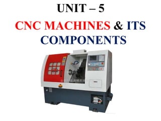
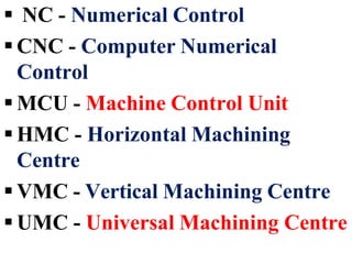
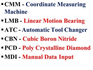
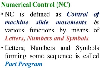
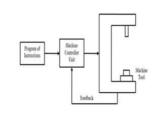
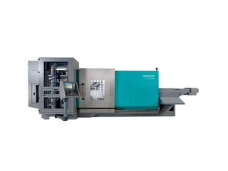
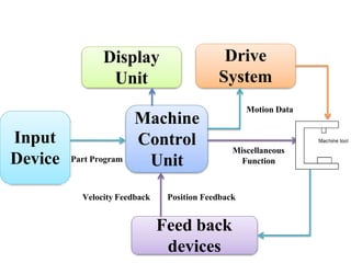
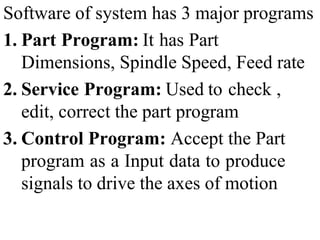
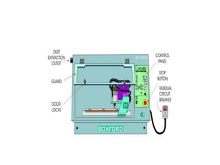
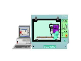
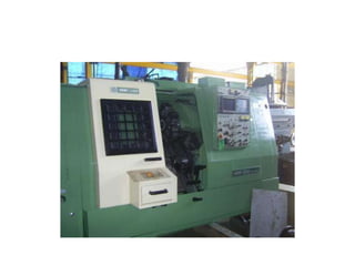
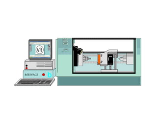
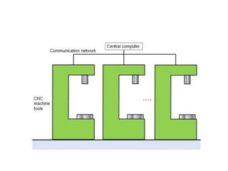
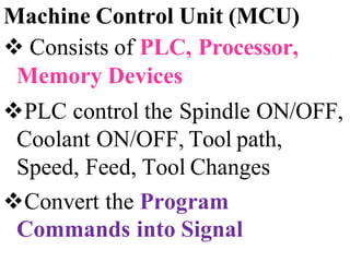
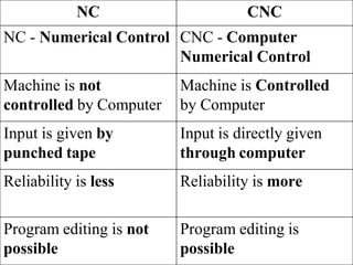
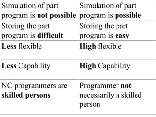
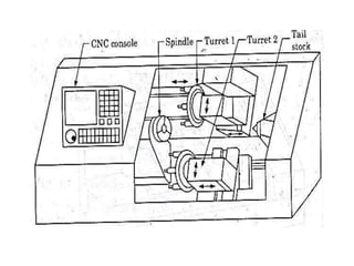
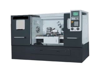
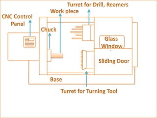
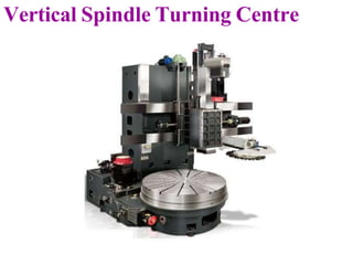
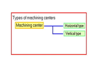
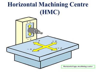
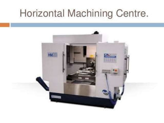
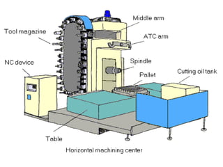
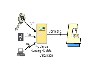
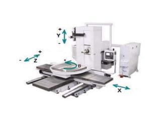
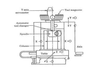
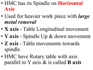
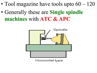
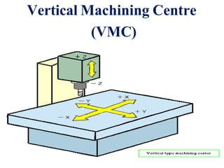
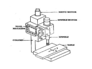
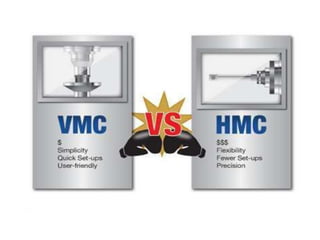
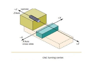
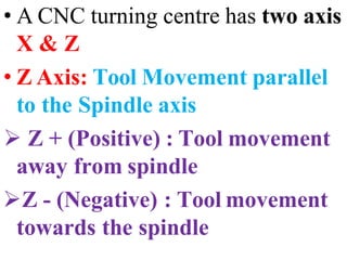
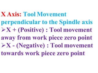
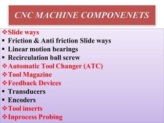
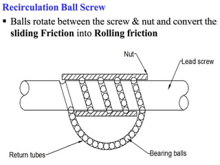
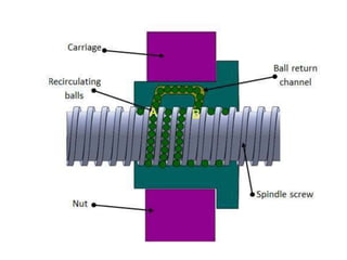
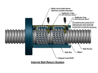
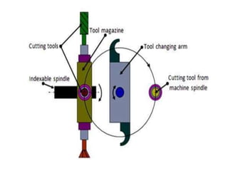
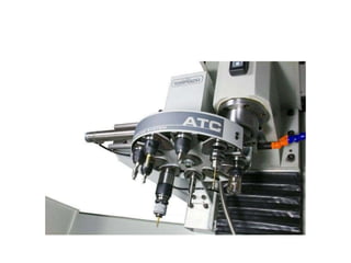
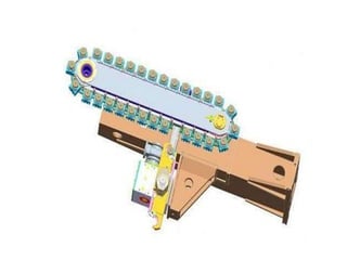
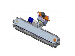
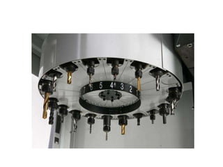
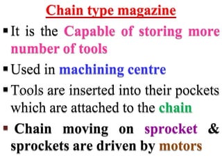
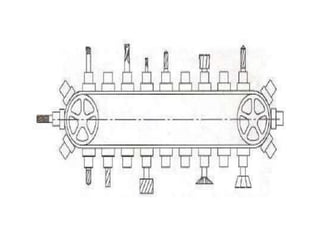
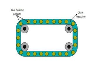
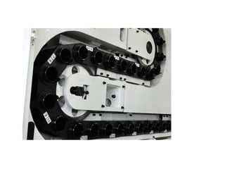
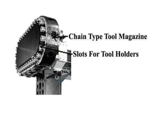
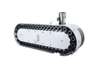
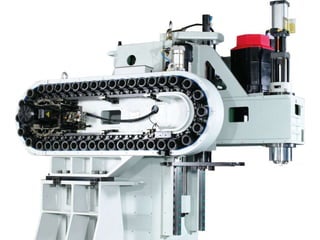
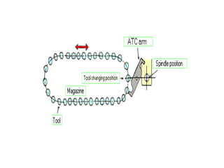
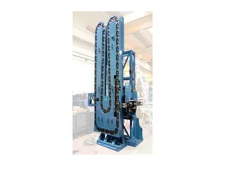
The document discusses various components used in CNC machines. It describes Numerical Control (NC) and Computer Numerical Control (CNC). Key components discussed include the machine control unit, feedback devices, automatic tool changer, tool magazine, and slide ways. The document also summarizes different types of CNC machines like turning centers and machining centers. It provides details on their main parts and axis of motion.
This document provides an overview of common devices and components used in CNC systems. It discusses Numerical Control (NC) and Computer Numerical Control (CNC), and describes the basic components of a CNC system including the Machine Control Unit, operator control panel, servo control unit and drives, and feedback devices. It also summarizes different types of CNC machines like turning centers, machining centers, and coordinate measuring machines. Key components of CNC machines such as slideways, automatic tool changers, tool magazines, and feedback devices are also outlined.
CNC (Computer Numerical Control) programming involves storing machining instructions as a program using letter addresses like G and M codes. This document provides an overview of CNC programming concepts like tool paths, interpolation types, common G and M codes, and the elements of a basic CNC system. It also discusses CAD/CAM software used for designing parts and generating CNC programs, and provides an example APT program for a cylindrical part.
This presentation is prepared as per syllabus of "COMMUNICATION ANALYSIS AND SKILL DEVELOPMENT PROGRAM (CASP)" prescribed by BOARD OF TECHNICAL EDUCATION, KARNATAKA for 5th sem diploma all branches.
This pptx is prepared by lots of information in websites,Textbooks(Author B
A Srinivas and M R Manjunath),And guidance of our lecturers Srinath V- B.E,FIE & M D Dayanand- B.E . SET Polytechnic, Melukote
The document discusses advantages of CNC machines including high accuracy, less floor space required, less manufacturing time, lower inspection time and costs, and improved surface finish. It then explains open loop and closed loop control systems, describing how feedback devices in closed loop systems allow for more precise manufacturing. Finally, it defines the axes of VMC and lathe machines, compares them, and discusses automatic tool changing mechanisms and types of tool magazines.
The document describes an industrial training institute that offers a 24-week CNC machining and programming course. The course covers topics like CNC turning, milling, programming using Fanuc and Siemens controllers, tooling, safety procedures, and more. It is aimed at candidates with qualifications in mechanical/production fields and includes both theoretical and practical training.
NC machine tools are controlled by programmed instructions without a human operator. The NC program contains a set of instructions that controls axis motion. The main components of an NC machine are the part program, programming tape, machine control unit, and machine tool. The MCU reads and interprets the program to control the machine tool's functions like spindle speed, tool positioning, and feed rate. NC machines offer benefits like high accuracy, reduced scrap, and increased productivity compared to conventional machining.
The document discusses CNC programming and machining. It defines CNC and describes how a typical CNC system consists of six main elements: the part program, program input device, machine control unit, drive system, machine tool, and feedback system. It then explains key aspects of CNC programming including common G and M codes, tool paths, absolute and incremental positioning, and provides an example program.
CNC machines are making parts around the world for almost every industry. They create things out of plastics, metals, aluminum, wood and many other hard materials. The word “CNC” stands for Computer Numerical Control, but today everyone calls it CNC. So, how do you define a CNC machine? All automated motion control machines have three primary components – a command function, a drive/motion system, and feedback system. CNC machining is the process of using a computer-driven machine tool to produce a part out of solid material in a different shape
CNC machines allow for precise and automated control of machine tools through computer programs. A CNC machine uses computerized controls and motors to precisely position and guide the tool or workpiece through the machining process. The presentation discusses the evolution of numerical control from its origins in the 1940s to meet production demands. It describes the basic components and functions of CNC machines including their programming, different types of machines like mills and lathes, and how they automate processes traditionally done manually. An example program for machining a cylindrical part is provided to demonstrate how G-codes specify operations.
This presentation provides an overview of CNC machines. It discusses that CNC machines use computer programs to control slide movements and machine functions rather than a human operator. The evolution of numerical control is described beginning in 1947 with the development of using punched cards to operate digitron systems. Different types of CNC machines such as mills, lathes, and EDM machines are covered. The presentation also discusses CNC programming basics including codes, tool paths, and an example programming for a cylindrical part.
CNC machining center and CNC controllerssushma chinta
CNC machining centers allow for multi-axis machining of workpieces in a single setup under program control. They include vertical and horizontal machining centers. Vertical machining centers hold the workpiece on a table that moves in the X-Y axes while the spindle moves in the Z axis. Horizontal machining centers use a rotary table to machine all sides of cube-shaped parts. Modern CNC machining centers feature automatic tool changers, workpiece positioning, and pallet changers to increase efficiency. Common CNC controllers include FANUC and Siemens controls, which provide precision motion control and programming capabilities.
Introduction to CNC machine and Hardware. aman1312
Complete detailing of cnc machine and its operations with its required hardware necessary for increasing its Automation and increasing its manufacturing capability. Also increase in complex shape manufacturing.
Cnc tooling for cnc machine(130670119596)Kushal Shah
we have seen what the NC machine is and its various
parts, it is easier to understand what the CNC machine is. CNC is
the short form for Computer Numerical control. We have seen that
the NC machine works as per the program of instructions fed into
the controller unit of the machine. The CNC machine comprises of
the mini computer or the microcomputer that acts as the controller
unit of the machine. While in the NC machine the program is fed
into the punch cards, in CNC machines the program of instructions
is fed directly into the computer via a small board similar to the
traditional keyboard.
CNC machines operate based on coded instructions to control machine tools. A CNC system includes a part program, program input device, machine control unit, drive system, machine tool, and feedback system. CNC machines can move tools in either a point-to-point or continuous path manner and use either open or closed loop control systems. Common types of CNC machines include vertical turning lathes, roll turning and center lathes, and deep hole boring machines. CNC machines are used for various manufacturing applications such as cutting, drilling, milling, welding, boring, and more.
The document provides an overview of numerical control (NC) and computer numerical control (CNC) machines. It discusses:
1) The historical development of NC from mechanized production equipment to programmable automation using NC, PLCs, and robots.
2) The basic definition and components of an NC machine, including the numerical controller, NC code, and interactions between the operator and machine.
3) The main components of NC machines - the machine control unit, machine tool, and various control units. It also discusses different types of machine control units.
4) Key aspects of NC motion control including point-to-point and continuous path control, open and closed loop systems, and different
CNC Programming for Begainer.
1.Easy Mehtod.
2.Complete Theoritical Knowledge.
3.Motion and coordinate system for NC machine.
4.Axes convention of VMC & HMC.
5.How to make Part Programming.
6.Coordinates System.
7.Programming Format.
8.List of G Codes And M Codes.
9.How to Use of Above Codes In Programme.
10.Reference Point and Return of Machine.
This describes the mechanism of Computer Numerical Control along with its types, control system, motion system, Programming of CNC, G codes, Part programming, adaptive control machining etc.
The document discusses CNC turning and milling centers. It defines CNC as computer numerically controlled automation of machine tools. Milling involves rotating cutting tools to produce flat and helical surfaces. CNC lathes and mills have automatic tool changers and workpiece positioners. CNC milling is similar to drilling and cutting and can perform many of the same operations. The document lists materials that can be machined and advantages of CNC like reduced lead times, errors, costs, and inspection needs.
This document provides an introduction to computer numerical control (CNC) machines. It discusses that CNC machines operate using programmed codes rather than manual control. The document outlines various CNC operations like milling and drilling. It describes the advantages of CNC machines as being able to operate continuously with high accuracy, batch production, and ability to update software. Five-axis CNC machines are discussed as able to machine complex shapes in a single setup. Specifications are provided for a sample five-axis CNC machine including its travel distances and spindle capabilities.
M.P- II-UNIT V - CNC MACHINE TOOLS AND PART PROGRAMMING.pptMohanumar S
The document discusses the history and evolution of CNC machine tools. It begins with the development of numerical control in the 1940s using punched cards and tape to program machines. This evolved into computer numerical control in the 1970s with the integration of smaller, less expensive computers directly into machine tools. The document then describes the hardware components and configuration of CNC machines, including their control units, drives, slideways, spindles, and programming. It also covers different CNC machine types like machining centers and turning centers, as well as their programming and control systems.
The document discusses computer aided manufacturing (CAM) and introduces MasterCAM software. It defines CAM as using computer-controlled machines to automate production. MasterCAM allows creating 2D drawings and generating tool paths for CNC machining. It supports importing designs from other CAD programs and includes tools for planning tool paths, selecting machining parameters, and generating NC code to operate computer-controlled machines.
The document provides an overview of fundamentals of CNC technology. It discusses the history of NC and CNC machines, components of a CNC machine like its control system and drive motors, how CNC machines work by precisely controlling axes movements, applications in various industries, and advantages like flexibility and precision over conventional machine tools. The document also covers establishing coordinate systems, different CNC machine types including lathes, milling machines and machining centers, and grinding processes.
This presentation provides an overview of a summer internship training on computer numerical control (CNC) machining. It introduces concepts related to computer-aided manufacturing (CAM) such as the definition and advantages of CAM. It also defines numerical control and CNC, compares NC and CNC machines, and discusses the different types of CNC machine tools. The presentation describes the elements, classification, advantages, and disadvantages of CNC machine tool systems. It also covers basic CNC topics like axis designation, machine versus work zero, coding systems, and the controls of specific CNC turning and milling machines.
Computer Numerical Control (CNC) Machining is the process through which computers control machine-based processes in manufacturing. The kinds of machines controlled include lathes, mills, routers and grinders – all used for manufacturing of metal and plastic products.
1. Numerical control (NC) systems were developed to automate machine tools using programmed sequences of instructions to control machine motions and functions.
2. NC systems use machine control units to read part programs containing coded instructions and translate them into mechanical actions to control machine tools.
3. Modern computer numerical control (CNC) systems provide greater flexibility over early NC systems by using computers to generate part programs and allow real-time adjustments to machine operations.
1. Numerical control (NC) systems were developed to automate machine tools using programmed sequences of instructions to control machine motions and functions.
2. NC systems use a machine control unit to read numerical input from a program and translate it into mechanical motions of the machine tool.
3. Modern computer numerical control (CNC) systems provide even greater flexibility and precision by using computers to generate and process NC programs and control machine tools.
This document provides an introduction and overview of CNC machines. It defines CNC as a manufacturing method that automates machine tools through preprogrammed computer software. The brief history section outlines the early developments of numerical control in the 1950s-60s and the emergence of CNC integration in the 1970s-2000s. The document then describes how a CNC machine works through CAD/CAM programming and toolpath generation, and compares CNC to traditional machines. It also reviews the typical components of CNC machines and provides an overview of common G-code and M-code functions. Finally, it outlines different types of CNC machines like milling, lathe, grinding, and turning centers.
The document discusses dip coating and electrodeposition processes. It describes dip coating as a process where a substrate is immersed in a coating material tank, removed, and allowed to dry. The dip coating process has three stages: immersion, dwell time, and withdrawal. Film thickness is controlled by withdrawal speed and viscosity. Electrodeposition coats one metal onto another to modify surface properties like corrosion resistance. It can deposit thin layers with precision and is well-suited for nano- and microtechnologies. Both dip coating and electrodeposition are used for applications like solar panels, electronics, jewelry, and automotive and mechanical parts.
The document discusses thermogravimetric analysis (TGA), which measures the change in mass of a sample as it is heated. It describes the different types of TGA, the principles behind how it works, factors that can affect results, and common applications. TGA is used to study things like decomposition temperatures, purity, reaction kinetics, and stability by precisely measuring mass changes that occur as a sample is heated in a controlled environment.
The document discusses the construction and components of CNC machines. It explains that CNC machines are built similarly to conventional machines but are computer-controlled. It describes the different axes, drives, measuring systems, tool changers, and magazines used in CNC lathes and milling machines. Automatic tool changers increase efficiency by rapidly switching between multiple tools stored in magazines.
CNC machines allow precise and repeatable control in machining through the use of NC programs. The history of CNC began in 1949 when the US Air Force asked MIT to develop a numerically controlled machine. Modern CNC machines use computer control linked directly to the machine controller. NC programs can be generated manually using G-code instructions or automatically using CAD/CAM software. Large NC programs are often run using DNC which "drip feeds" blocks of code from an external computer to the machine controller.
The document discusses the construction and components of CNC machines. It explains that CNC machines are built similarly to conventional machines but are controlled by computers. It describes the main components of CNC machines, including feed drives, measuring systems, work spindles, tool changers, and DNC systems. It also discusses automatic tool changers, which reduce idle time and improve productivity by automatically exchanging tools.
This document provides an introduction and overview of Numerical Control (NC), Computer Numerical Control (CNC), and Distributed Numerical Control (DNC) machine tools. It defines each type of machine tool and describes their basic components and programming methods. NC machines use programmed punched tapes to control automated functions, while CNC machines utilize a dedicated computer as the control unit. DNC systems connect multiple NC machines in real-time to a central computer for shared program storage and transmission. The document outlines the classification, advantages, and limitations of these different machine tool systems.
The document provides an overview of surface engineering processes and their timeline of development. It discusses various nitriding, plating, thermal spraying, and coating processes such as gas nitriding, plasma nitriding, hard chrome plating, electroless nickel plating, physical vapor deposition, chemical vapor deposition, high-velocity oxy-fuel spraying, high-velocity air-fuel spraying, detonation gun spraying, plasma spraying, and cold spraying. It provides details on the process, applications, advantages, and issues with some of these surface modification techniques.
Cladding is a metallurgical process that bonds layers of different metals together without fillers or adhesives. It involves applying extreme pressure, with or without heat, to physically bond the metal layers together. Common cladding methods include roll bonding, accumulative roll bonding, friction surface cladding, laser cladding, microwave cladding, rotary swaging, and plasma surface cladding. Each method utilizes unique parameters like temperature, pressure, coating materials, and equipment to achieve cladding. Cladding can produce composite metals with desirable properties from two or more bonded layers.
Chemical vapor deposition (CVD) is a process used to produce thin films by exposing a substrate to volatile precursors that decompose to form a deposited solid film. During CVD, the substrate is exposed to reactive gases in a chamber where chemical reactions form the desired deposit while volatile byproducts are removed. CVD can be used to deposit a wide variety of materials and has applications in semiconductors, coatings, optical fibers, composites and more.
Dip coating involves immersing a substrate in a coating material tank, removing it, and allowing the coated substrate to drain and dry. The process has three stages: immersion, dwell time to allow coating application, and controlled-speed withdrawal where faster speeds produce thicker coatings. Film thickness is controlled by viscosity and withdrawal rate. Dip coating is used for applications like windows, optics, and thin film coatings.
Michael Faraday was a British physicist and chemist in the 19th century who made many contributions to the field of electromagnetism. Some of his most important discoveries include the principles of electromagnetic induction, which established that a changing magnetic field can generate an electric current. He invented the electric motor, generator, and transformer based on these principles. Faraday established the laws of electrolysis through his experiments with electrolysis.
The document discusses various metal finishing processes including electroplating, phosphating, powder coating and their applications. It provides details on electroplating equipment and processes, cleaning and pretreatment methods before electroplating, and the electrical equipment used. It also discusses powder coating and describes the global market outlook for electroplating, phosphating and powder coatings.
TGA has some limitations in that it only measures mass changes during heating and cannot detect physical or chemical changes that do not alter mass. It is useful for determining purity and thermal stability, analyzing complex mixtures by decomposition, and studying reaction kinetics by measuring mass changes over time. TGA can also be used to study catalyst behavior, analyze dosage forms in medicine, measure oxidative stability, estimate product lifetimes, and determine moisture and solvent content.
Thermogravimetric analysis (TGA) is a technique that measures the mass of a sample as it is heated, allowing one to see mass changes associated with decomposition, sublimation, or other physical/chemical changes. TGA curves are influenced by factors like heating rate, furnace atmosphere, sample weight and particle size. TGA has applications in determining purity/stability, analyzing mixtures and complex systems, studying reaction kinetics, and analyzing materials in fields like medicine, catalysis, and oxidative stability testing.
This document discusses various methods of surface preparation for coatings. Traditional methods like sandblasting can be hazardous and harmful to the environment. A newer plasma treatment method uses low-temperature plasma discharge to clean and functionalize surfaces without pollution. Plasma treatment improves hardness, wear and corrosion resistance of surfaces and allows for better coating adhesion. While plasma treatment shows advantages over traditional methods, further optimization is still needed regarding glow discharge stability and repair of coated surfaces.
Surface engineering involves modifying the surface properties of materials to make them more robust and resistant to degradation from environmental interactions. It can improve properties like corrosion and wear resistance. There are many traditional surface engineering techniques like painting, electroplating, and thermal spraying as well as more advanced methods such as physical vapor deposition, chemical vapor deposition, ion implantation, and laser treatment. Surface engineering provides benefits like reduced costs, extended product lifetimes, and improved performance and is used in many industries.
Differential Mechanical Analysis (DMA) is a technique where a small cyclic deformation is applied to a sample to study its response to stress, temperature, and frequency. DMA measures a material's mechanical and viscoelastic properties by applying a sinusoidal stress and measuring the strain, allowing the complex modulus to be determined. The temperature or frequency can be varied to measure transitions and locate glass transition temperatures. DMA provides important information about polymers and other materials.
Differential scanning calorimetry (DSC) is a thermal analysis technique that measures the heat flow into or out of a sample as it is heated, cooled, or held at constant temperature. DSC can be used to analyze physical and chemical changes that involve endothermic or exothermic processes, such as phase transitions, crystallization, melting, and curing. DSC provides quantitative and qualitative material characterization by measuring the heat flow and temperature differences between a sample and an inert reference sample as they undergo temperature changes. The heat flow is directly related to transitions in materials and can be used to determine transition temperatures and associated enthalpies.
Thermal Gravimetric Analysis (TGA) is a technique that measures the change in mass of a sample as it is heated. It involves heating a sample in a controlled environment and measuring its mass loss over time or temperature. TGA can be used to determine purity, composition, thermal stability, and kinetics of reactions by producing a thermogravimetric curve that plots mass change against temperature or time.
A spectrophotometer is an instrument that measures the amount of light transmitted through a sample. It uses either ultraviolet or visible light, and detects molecules in a solution based on which wavelengths of light are absorbed. It works by shining a light source through a sample, and measuring how much light is absorbed, reflected, or transmitted. This allows it to determine characteristics of unknown samples by comparing them to measurements taken of samples of known concentration.
Walmart Business+ and Spark Good for Nonprofits.pdfTechSoup
"Learn about all the ways Walmart supports nonprofit organizations.
You will hear from Liz Willett, the Head of Nonprofits, and hear about what Walmart is doing to help nonprofits, including Walmart Business and Spark Good. Walmart Business+ is a new offer for nonprofits that offers discounts and also streamlines nonprofits order and expense tracking, saving time and money.
The webinar may also give some examples on how nonprofits can best leverage Walmart Business+.
The event will cover the following::
Walmart Business + (https://business.walmart.com/plus) is a new shopping experience for nonprofits, schools, and local business customers that connects an exclusive online shopping experience to stores. Benefits include free delivery and shipping, a 'Spend Analytics” feature, special discounts, deals and tax-exempt shopping.
Special TechSoup offer for a free 180 days membership, and up to $150 in discounts on eligible orders.
Spark Good (walmart.com/sparkgood) is a charitable platform that enables nonprofits to receive donations directly from customers and associates.
Answers about how you can do more with Walmart!"
This presentation includes basic of PCOS their pathology and treatment and also Ayurveda correlation of PCOS and Ayurvedic line of treatment mentioned in classics.
How to Setup Warehouse & Location in Odoo 17 InventoryCeline George
In this slide, we'll explore how to set up warehouses and locations in Odoo 17 Inventory. This will help us manage our stock effectively, track inventory levels, and streamline warehouse operations.
A workshop hosted by the South African Journal of Science aimed at postgraduate students and early career researchers with little or no experience in writing and publishing journal articles.
Exploiting Artificial Intelligence for Empowering Researchers and Faculty, In...Dr. Vinod Kumar Kanvaria
Exploiting Artificial Intelligence for Empowering Researchers and Faculty,
International FDP on Fundamentals of Research in Social Sciences
at Integral University, Lucknow, 06.06.2024
By Dr. Vinod Kumar Kanvaria
Main Java[All of the Base Concepts}.docxadhitya5119
This is part 1 of my Java Learning Journey. This Contains Custom methods, classes, constructors, packages, multithreading , try- catch block, finally block and more.
7. Numerical Control (NC)
• NC is
machine
various
defined
slide
functions by means
as Control of
movements &
of
Letters, Numbers and Symbols
• Letters, Numbers and Symbols
forming some sequence is called
Part Program
8.
9. 1.Starting and stopping of
machine tool spindle.
2.Controlling the spindle speed.
3.Positioning the tool tip
4.Guiding the tool in desired
paths
5.Controlling the feed rate.
6.Changing of tool in the spindle
10.
11.
12.
13.
14.
15.
16.
17. It is a Numerical Control system,
which uses a Computer to perform
all or some of the basic numerical
control functions
In CNC, the program is entered
once and they stored in the
computer memory
18.
19.
20.
21.
22. A CNC system consist of the
following
1.Machine Control Unit (MCU)
2.Operator Control Panel
3.Servo Control Unit & Drives
4.Feedback Devices
23. In CNC systems the part program is
fed into the computer.
Then the instructions are read by the
controller to convert it into signals
that activate the machine tool.
The signals are sent to the machine
tool for performing different
operations.
26. Software of system has 3 major programs
1. Part Program: It has Part
Dimensions, Spindle Speed, Feed rate
2. Service Program: Used to check ,
edit, correct the part program
3. Control Program: Accept the Part
program as a Input data to produce
signals to drive the axes of motion
27.
28.
29.
30.
31.
32. Machine Control Unit (MCU)
Consists of PLC, Processor,
Memory Devices
PLC control the Spindle ON/OFF,
Coolant ON/OFF, Tool path,
Speed, Feed, Tool Changes
Convert the Program
Commands into Signal
33. Operator Control Panel
Provide the interaction
between User & CNC
system
Consists of Monitor,
Feather touch keyboard,
machine control panel
34.
35. Servo Control Unit & Drives
PLC gives command signal
to servo drives , this command
signal values are converted
into actual movement on the
machine by servo drives
36. Feedback Devices
PLC receives feedback signal about
actual movement of the machine tool
through feedback devices
Feedback Devices are Transducers
& Encoders
This feedback signals are compared
with the Input signals and error
correction is done
37.
38. Storage of more than one part program
Various forms of Data Input
Program Editing
Graphical Display of Cutter path &
shape of the finished job before actually
running the program is possible
Sub program facility for repetitive
machining sequence also possible
39.
40. • Increased Productivity
• High Accuracy
• Reduced Time
• Reduced man power
• Simulation of program is available
• Increased Safety operations
• Lesser Floor place
41.
42. NC CNC
NC - Numerical Control CNC - Computer
Numerical Control
Machine is not
controlled by Computer
Machine is Controlled
by Computer
Input is given by
punched tape
Input is directly given
through computer
Reliability is less Reliability is more
Program editing is not
possible
Program editing is
possible
43. Simulation of part Simulation of part
program is not possible program is possible
Storing the part
program is difficult
Storing the part
program is easy
Less flexible High flexible
Less Capability High Capability
NC programmers are
skilled persons
Programmer not
necessarily a skilled
person
44.
45. • CNC Turning centre is a machine
tool capable of performing
various Turning & related
operation in one setup under CNC
system
• CNC turning centers are designed
mainly for machining shaft-type
work pieces which are supported
by a chuck
46. CNC turning centre Tool Turret have
Capacity of 8 to 12 tools
Two axis control:
Z axis - Parallel to Spindle axis
X axis - Perpendicular to Spindle axis
Types of CNC turning Centre:
• Horizontal Spindle Turning Centre
• Vertical Spindle Turning Centre
53. • Vertical
used for machine
CNC lathes widely
heavy
components.
• Some of these machines can
also be used for milling
operations. Such machines are
sometimes known as turn -
mill centers.
54.
55.
56.
57.
58. • A machining centre consists of
machine tools, usually numerically
controlled,
automatically
capable of
drilling, reaming,
tapping, milling and boring the
multiple faces of a part with tool
magazine, Automatic tool changer,
automatic pallet changer.
59. Five axis control:
X axis, Y axis, Z axis - Linear Movement
A axis - Spindle Tilt
B axis - Table rotation
Types of CNC Machining Centre:
• Horizontal Spindle Machining Centre
(HMC)
• Vertical Spindle Machining Centre
(VMC)
60. Main Parts of CNC Machining Centre:
• Bed
• Column
• Spindle
• Table
• Servo Mechanism
• Tool Magazine
• Automatic Tool Changer (ATC)
• Automatic Pallet Changer (APC)
68. • HMC has its Spindle on Horizontal
Axis
• Used for heavier work piece with large
metal removal
• X axis - Table Longitudinal movement
• Y axis - Spindle Up & down movement
• Z axis - Table movements towards
spindle
• HMC have Rotary table with axis
parallel to Y axis & is called B axis
69. • Tool magazine have tools upto 60 – 120
• Generally these are Single spindle
machines with ATC & APC
72. • VMC has its Spindle on Vertical Axis
• Used for heavier work piece with large
metal removal
• X axis - Table Longitudinal movement
• Y axis - Table cross wise movement
• Z axis - Spindle Up & down movement
• VMC have Rotary table with axis
parallel to X axis & is called A axis
73.
74. •Tool magazine have upto
60 tools
•Generally these are
Single spindle with ATC
Multi spindle with
Turret Head
75.
76.
77.
78.
79. • In CNC machine tool, each of
the axis of motion is controlled
by axis feed drive mechanism
• Primary axis of motion are
referred as X, Y and Z axis
• Rotary axis : A, B, C identifies
the rotary motion about X, Y
and Z axis
82. • A CNC turning centre has two axis
X & Z
• Z Axis: Tool Movement parallel
to the Spindle axis
Z + (Positive) : Tool movement
away from spindle
Z - (Negative) : Tool movement
towards the spindle
83. X Axis: Tool Movement
perpendicular to the Spindle axis
X + (Positive) : Tool movement
away from work piece zero point
X - (Negative) : Tool movement
towards work piece zero point
88. • A CNC Machining centre has
three axis X , Y & Z
• Z Axis: Up & Down movement
of Spindle & tool
Z + (Positive) : Tool movement
away from Workpiece
Z - (Negative) : Tool movement
towards the Workpiece
89. •X Axis: Table longitudinal
movement
X + (Positive) : Table
movements towards right
X- (Negative) : Table
movements towards left
90. • Y Axis:
movement
Y +
Table Crosswise
(Positive)
movements away
: Table
from the
machine column
Y - (Negative) : Table
movements towards the machine
column
92. • CMM is an Electro mechanical
system designed to determine
the location, orientation,
dimensions and geometry of a
object
• CMM is used to measure
various features of work piece
by using Probes
114. Slide ways
Precise positioning and Repeatability of
tool slides are the major
requirements of CNC
machine
functional
machines.
The inaccuracies that caused are mainly
due to the stick slip motion when plain
slide ways (metal to metal contact) are
used.
Slide ways are used for movement
between tool members of machine tool
such as carriage & bed in a lathe
115. Requirement of Good Slide ways:
• Low wear
• Negligible stick-slip
• Low price
• Low co-efficient of friction properties
• Good surface finish on slideway
surface
• High Stiffness
123. Antifriction Slideways
It involves intermediate rolling
member(Balls or Rollers)
between the sliding members,
thus reducing the friction
Low friction, No stick slip,
high load capacity
134. •The device used to pick up
a tool from Tool magazine
and replace it with the tool
in the spindle with in 3 to
7 seconds is called ATC
•Reducing idle time during
tool changing operations
135.
136.
137.
138.
139.
140. 1. ATC arm Rotates through 90º from the
Rest position
2. One end grips tool in the magazine &
another end grips tool in the spindle
3. Both tools are pulled out
4. ATC arm rotates through 180º
5. It inserts new tool to the spindle & old
tool to the magazine
6. ATC arm Rotates through 90º & goes to
the Rest position
145. 5. Arm rotates & go to rest position
AT
C
Spindl
e
Tool
Magazine
146.
147. • The system of arrangement which
holds large number of tools is
called Tool Magazine
• It is specified by Storage Capacity
& Shape
• Storage capacity ranges from 12 -
200
• Used in CNC turning centre & CNC
machining centre
149. Tool Turret
It is the Simplest form of tool
magazine
It consists of tool storage without
tool changer
Turret is indexed in required
position for desired operation
Tool can be easily identified
Tool change time is more
150.
151.
152.
153. Disc or Drum Type Tool Magazine
It is the Rotates to get the desired
tool in position with tool change
arm
It carries 12 - 50 tools
If diameter of the disc is large more
number of tools can be hold
It have pockets where the tools can
be inserted
154.
155.
156.
157. Chain type magazine
It is the Capable of storing more
number of tools
Used in machining centre
Tools are inserted into their pockets
which are attached to the chain
Chain moving on sprocket &
sprockets are driven by motors
158.
159.
160.
161.
162.
163.
164.
165.
166. Rack Tool Magazine
It is the Cost efficient
alternative to usual tool
magazine system
It carries up to 400 tools
It consists of high tool storage
without tool changer
175. • The electronic devices such as
Transducer & Encoders used for
giving the position & velocity of the
machine elements are called
Feedback devices
• Based on feedback control the
systems are classified as
1. Open loop control system
2. Closed loop control system
176. Open loop control system:
Machin
e
Contr
ol
Unit
Drive
Moto
r
Machine
tool
slide
The machine tool control system in which there is
No feed back devices to compare the actual
position of the cutting tool or work piece with the
input signals are called open loop control systems
177.
178. Closed loop control system:
Machin
e
Contr
ol
Unit
Drive
Moto
r
Machine
tool
slide
The machine tool control system in which there are
feed back devices to compare the actual position of
the cutting tool or work piece with the input signals
are called open loop control systems
Velocity feed
back
Positionfeed
179.
180.
181. • Transducers are electronic devices
used for converting the physical
quantities like Speed,
velocity, Displacement
Feed,
into
Electronic signals that give feed
back
• Two types of transducers
1.Linear transducer
2.Rotary Transducer
190. • Encoders are devices used to
measure the linear movement of
the Machine table
• Any devices that is used to give
positioning feedback to the control it
applies a code or changes
information into coded form
191. • Two types of encoders
1. Linear encoders
2. Rotary encoders
192. Rotary encoders
A rotary encoder is a type of
sensor that when mounted to
the shaft of the motor can
detect its angular position
Its is made from light source,
optical sensor, disc with small
slits cut into it like spokes
198. • It is the process of performing the
inspection procedure during
manufacturing operation.
• In this process manufacturing as
well as inspection are done
simultaneously
• The process of inspection is called
& device used for
is called Inspection
probing
inspection
Probe