Download to read offline

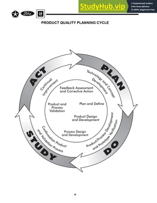


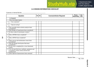
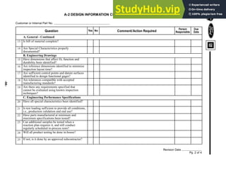
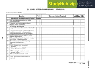
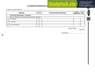
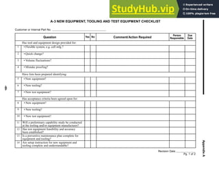
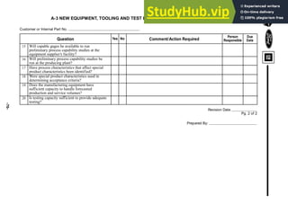
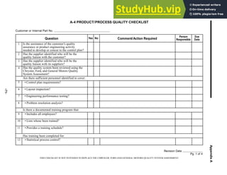
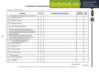
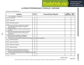
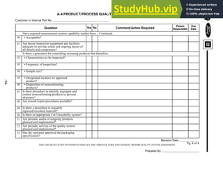
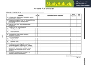
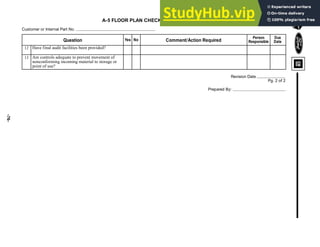


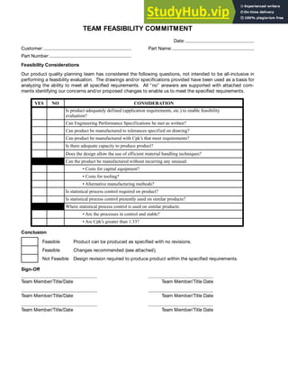
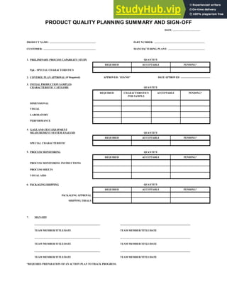


The document provides guidelines for Advanced Product Quality Planning (APQP) and Control Plans developed jointly by Chrysler, Ford, and General Motors. It aims to standardize quality planning processes for suppliers. The manual outlines the key phases of quality planning including planning and defining the program, product and process design, validation, feedback and assessment. It provides checklists and guidelines to ensure customer requirements are met through simultaneous engineering and defect prevention.