Download to read offline
![International Journal of Scientific Research and Engineering Development-– Volume 3 - Issue 5, Sep - Oct 2020
Available at www.ijsred.com
ISSN : 2581-7175 ©IJSRED: All Rights are Reserved Page 159
ACQUISITION SYSTEM
Mr. Hariharan.R.[1]
, Mr.Mohamed naleem.M. [2]
, Ms. Preethi.D. [3]
, Ms. Sivaranjani.A. [4]
, Mr.Subash.D. [5]
[1]
Assistant Professor
[2 to 5]
UG students
Department of Electrical and Electronics Engineering, Sri Eshwar College of Engineering, Coimbatore – 641202.
E-mail: hariharan.r@sece.ac.in , mohamednaleem.13@gmail.com, preethiiduraiswamy@gmail.com , sivaranjani22116@gmail.com ,
subashgr622@gmail.com
----------------------------------------------------------************************------------------------------------------------------------
ABSTRACT:
This paper tells us about how smart machines seem revolutionary, like something out of science fiction, with
various capabilities. However, acquisition systems are the next step in a history of incremental advancement in
machines. The main idea of this project is to make the work of staff so convenient and in a smarter way. In various
universities the internal and the external examiners faces various difficulties while conducting examinations. It
minimizes the time duration taken by the staffs from the examination cell to the respective exam halls by displacing the
work of humans by machines. Powered by these machines, the new industrial revolution is changing how machine
builders design, also explains how manufactures operate today and in the future. It remains more flexible and also
expected to dramatically change the nature of work and other society norms.
KEYWORDS—efficient examination, fast-moving digital transformation, implementing technology, case based reasoning,
fuzzy logic and dramatic efficiency.
----------------------------------------------------------************************------------------------------------------------------------
I. INTRODUCTION
The world is been completely automated. Currently, we
inhabit a world in which several applications use a computer inside
another device, realizing control and processing with increased
performance. Nowadays the computing technologies enables the
creation of computational platforms which supports the new and
smarter machine. Overall, by creating a collaborative environment
with cheaper non-recurrent engineering cost and highly beneficial
manner.
This highly interactive features go beyond traditional
systems. This paper reviews technology advancements that could
enable the research and development of new intelligent systems in a
profitable manner. The machine monitoring also enables preventative
maintenance which helps to avoid component failure. It also reduces
the damage to the components.
II. PROBLEM STATEMENT
In various universities organizing an examination seems
very difficult as the examiners have to arrange the paper bundles
before several days before exams. It includes lot of manpower and
time consumption. The examination crew takes a longer time for
arranging the papers to distinct classes and then they have to carry
the bundles to a longer distance. It leads to stress and burden for the
crew members of the examination cell. In order to avoid this
problem, we have found out the acquisition system, which displaces
the human work easily.
Acquisition system is a collection of hardware and
Software components which controls the physical characteristics.
The bundles are placed inside the system and by using the raspberry
3b+, we monitor and control the programming. By using the rack and
pinion set, the booklets are arranged and a motor is set up at the ends.
By scanning the RFID reader and giving the input, the internal and
the external examiners can collect the papers at the respective halls.
III. SURVEY
Small survey was done in nearly five universities in and
around our city. When we went on examining every
examination cell, we found staffs facing various difficulties
while organizing the examination as they have to arrange the
question booklets and answer booklets several days before the
examination. In addition to this, they have to arrange the
bundles to various centers as it covers longer distance. It also
consumes more manpower work and time consumption. This
analysis helped us to come out with designing a single
machine for doing the entire tasks quickly.
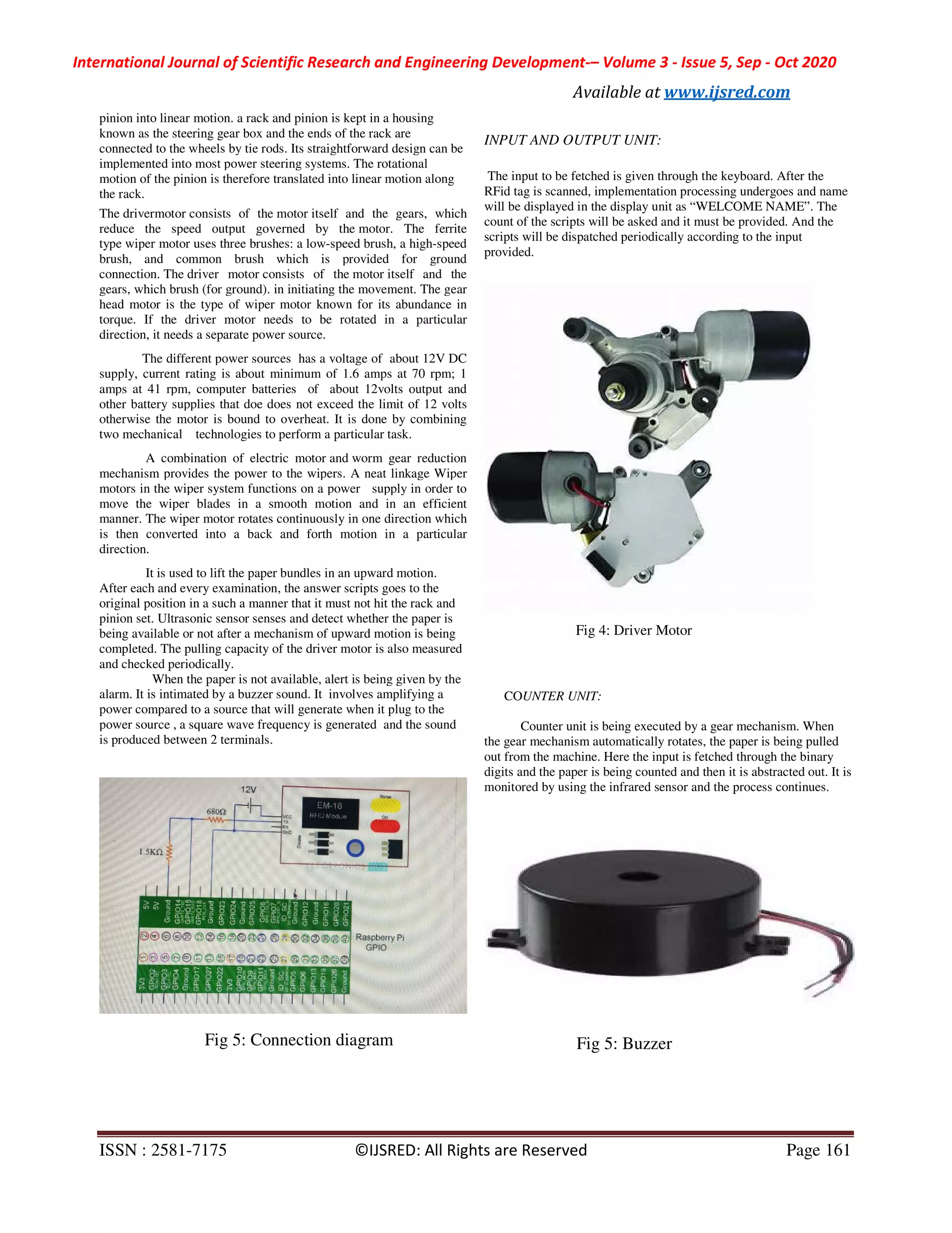
IV. HARDWARE COMPONENTS
In our project, acquisition system, we have developed a
mechanical setup for continuous and efficient process. The following
are the hardware components used,
1. Raspberry pi
2. RFID reader
3. Rack and pinion
4. Wiper motor
5. Buzzer
6. Display board
7. Light-emitting diode
RESEARCH ARTICLE OPEN ACCESS](https://image.slidesharecdn.com/ijsred-v3i5p24-200919143306/75/Acquisition-System-1-2048.jpg)

![International Journal of Scientific Research and Engineering Development-– Volume 3 - Issue 5, Sep - Oct 2020
Available at www.ijsred.com
ISSN : 2581-7175 ©IJSRED: All Rights are Reserved Page 163
V. REFERENCE
[1] Raspberry Pi Technology, Harshada Chaudhari Student of Third
Year of Computer Engineering, Shri Sant Gadge Baba College of
Engineering and Technology, Bhusawal, North Maharashtra
University, Jalgaon, Maharashtra, India
[2] Wireless Access Networks for Raspberry Pi Luca De Nardis,
Maria-Gabriella Di Benedetto DIET Department Sapienza University
of Rome Rome, Italy ,Stefano Olivieri The MathWorks Turin, Italy
[3] DESIGN OF RACK AND PINION STEERING FOR ALL
TERRAIN VEHICLE Ajay M. Tayde1, Sanket P. Golhar2, Shital R.
Ughade3, Nikita Ramdas Kakde4 1,2,3,4Student, Department of
Mechanical Engineering, PRMIT&R, Badnera, Amravati University,
Maharashtra (INDIA)
[4] Smart Id Card System using RFID Technology Leandre
Nsengumuremyi1 , Addepalli Sardhak2 , Vivek V3 1, 2, 3Computer
Science and Engineering Department, Jain University, International
Journal for Research in Applied Science & Engineering Technology
(IJRASET) ISSN: 2321-9653; IC Value: 45.98; SJ Impact Factor:
6.887
[5] Smart Wiper Control System N. M. Z. Hashim1 , S. H. Husin2 ,
A. S. Ja’afar3 , N. A. A. Hamid4 1,2,3,4 Faculty of Electronics &
Computer Engineering, Universiti Teknikal Malaysia Melaka, Hang
Tuah Jaya, 76100 Durian Tunggal, Melaka Malaysia](https://image.slidesharecdn.com/ijsred-v3i5p24-200919143306/75/Acquisition-System-5-2048.jpg)

This document describes an acquisition system designed to make the examination process more efficient. The system uses a Raspberry Pi to control various hardware components including an RFID reader, rack and pinion assembly, and motor. It is intended to reduce the time and effort required of staff to distribute exam materials by automating the process. When examiners scan their RFID tags, the system verifies their identity and allows them to retrieve the appropriate exam bundles via a motorized rack and pinion assembly. The goal is to minimize manual labor and speed up exam distribution using an automated hardware and software solution controlled by a Raspberry Pi microcontroller.


![[IJET-V1I4P5] Authors :Divya Lakshmi M , Dr. Ramesh R](https://cdn.slidesharecdn.com/ss_thumbnails/ijet-v1i4p5-150728164001-lva1-app6892-thumbnail.jpg?width=640&height=640&fit=bounds)