The document provides an overview of the LM628/629 motion control device. It describes the device's hardware architecture including the trajectory profile generator, PID filter, position decoder and other functional blocks. It discusses the device's operation in generating velocity profiles to control motor position, and how parameters like position, velocity and acceleration are represented and updated. It also covers the motor output port and operation of the LM628 and LM629 variants.
FPGA based synchronous multi-channel PWM generator for humanoid robot IJECEIAES
In this paper, synchronous multi-channel pulse width modulation (PWM) generator for driving servo motors of humanoid robot was proposed. In an application, the humanoid robot requires smooth and beautiful movement, therefore the PWM signal for each servo motor must be synchronized. Since microcontroller (slave) has no enough channels to generate synchronous PWMs for 32 servo motors, field programmable gate array (FPGA) was used as slave for the humanoid robot. The FPGA was controlled by microcontroller (master) using serial communication. Simulation results show the system can perform serial communication, synchronize, and convert data well. The system can also generate PWM simultaneously with accurate duty cycle and fix period of 20ms.
International Journal of Computational Engineering Research(IJCER)ijceronline
International Journal of Computational Engineering Research(IJCER) is an intentional online Journal in English monthly publishing journal. This Journal publish original research work that contributes significantly to further the scientific knowledge in engineering and Technology
Bi directional speed control of dc motor and stepper motor through mat lab us...eSAT Journals
Abstract In any industry speed control of an electric drive system is very critical and crucial. Every designer aims at achieving a control methodology having high degree of precision. But industry needs are ever evolving in nature. Hence it is very much essential that along with conventional speed control mechanisms we must also have simple interactive graphical based control strategies. Several algorithms/methodologies have been developed over the years to achieve speed control of motors. In this context by encompassing the usability of Mat Lab, work has been done to control the speed of stepper motor and DC motor using microcontroller. Microcontroller is programmed to achieve bi directional speed control. The main objective of this work is to develop the graphical user interface of motor control through mat Lab guide and the interface of the same with hardware via serial communication. PIC is used as the controller. Keywords— DC, PIC, μC, AC, GUI, IC
Interfacing Of PIC 18F252 Microcontroller with Real Time Clock via I2C ProtocolIJERA Editor
This paper describes a microcontroller based digital clock which can be used in real time systems. The system is constructed using PIC18F252 (microcontroller), DS1307 (real time clock IC) and its software program is written with C programming language. A 3v battery backup is provided to real time clock IC. Communication between PIC microcontroller and DS1307 takes place through I²C Bus protocol
An automatic wave probe reference setting mechanism in a high speed towing tankeSAT Journals
Abstract The wave generation system in a High Speed Towing Tank (HSTT) generates regular and irregular waves to simulate wave condition during ship model testing. A wave probe is used to measure the height of waves generated by the wave generation system which is placed at the centre of the towing tank from the wave generation system. Generally the initial wave height reference (zero-point) at no wave condition is set manually and it is difficult to set reference accurately and the procedure is time consuming. The work aims at development of an automatic mechanism for adjustment of zero point in HSTT. The intended system enables remote monitoring and setting wave probe height reference with better accuracy minimizing human intervention. The prototype results confirmed the efficacy of the proposed mechanism. Keywords: Towing Tank, Wave probe, Wave generating system.
IJRET : International Journal of Research in Engineering and Technology is an international peer reviewed, online journal published by eSAT Publishing House for the enhancement of research in various disciplines of Engineering and Technology. The aim and scope of the journal is to provide an academic medium and an important reference for the advancement and dissemination of research results that support high-level learning, teaching and research in the fields of Engineering and Technology. We bring together Scientists, Academician, Field Engineers, Scholars and Students of related fields of Engineering and Technology.
Development of Distributed Mains Monitoring and Switching System for Indus Co...iosrjce
Indus Complex at Raja Ramanna Centre for Advanced Technology (RRCAT) has two synchrotron
radiation sources, Indus-1 and Indus-2. Microtron is injector to both the machines which sends electron pulses
to the Booster. A new, microcontroller based, distributed mains monitoring and switching system is developed
for Indus complex. It facilitates remote monitoring and switching of AC power switches to various subsystems. It
includes interfacing with power switches/Miniature Circuit Breakers (MCBs) of Indus machine subsystems. This
work involves development of hardware, firmware for microcontroller, implementation of communication
protocol; LabVIEW based server and client application. The developed system allows remote monitoring and
switching of MCBs from main control room.
Design and Implementing Novel Independent Real-Time Software Programmable DAQ...Editor IJCATR
The crucial features of many demanding applications like industry and aerospace are data acquisition and telemetry. It is
vital to observe and analyse the real time performance, in launch vehicle systems,so that designs can be certified and tuneablefactors
could be regulated to intensification the act and competence. At present used DAQ structures are of augmented size, weight and turn out
to be exorbitant and power hungry. This article introduce a new mission-independent real time software programmable DAQ system
using multipurpose MCU and sigma delta ADCs are planned,taking into account size, weight, costand act without compromiseon
precision, firmness and drift act. Additional digital filtering steps are also added to progress the system act. This system isproficientfor
directconnectionswithdiverse pressure and temperature sensors whichinterfaces 32 low frequency channel and two high frequency
channels. The system planned operates in two modes; one is data acquisition mode and another is program mode. Operativepower
lesseningmethods and wireless interface protocol between diverse data acquisition modules is also affected upon as avenues for future
work.
Reviews of Cascade Control of Dc Motor with Advance Controllerijsrd.com
The proportional- integral-derivative (PID) control is the most used algorithm to regulate the armature current and speed of cascade Control system in motor drives. The controller uses two PID controllers. One PI controller is for speed control and second PID controller for current control in cascade structure. Inner loop is for the current control which is faster than the outer loop. Outer loop is for speed control. The output of the encoder is compared with a preset reference speed. The output of the PI controller is summed and is given as the input to the current controller.
IJERA (International journal of Engineering Research and Applications) is International online, ... peer reviewed journal. For more detail or submit your article, please visit www.ijera.com
Nowadays every system is automated in order to face new challenges. In the present days, Automated systems have less manual operations, flexibility, reliability and accurate. Due to this demand, every field prefers automated control systems. Especially in the field of electronics automated systems are giving good performance in industries and on roads. The mechanical arrangement is arranged to the robot as a robotic car using solar energy. This project handles with two operations. One hand Autonomous, based on sensor application robotic car moves itself by avoiding an obstacle and to move in its paths. It explains the method of interfacing solar panel, relay circuit board, IR sensor to the car and how to send the command to the microcontroller to drive the car autonomously. On the other hand, it controls using BLUETOOTH modem, in order to control the robotic car using BLUETOOTH, the user has to send the predefined messages to the modem. When the modem receives these predefined messages, it intimates the same to the microcontroller. The microcontroller upon receiving the information from the modem acts in accordance with the message, making it a highly automated application.
this is a complete summer training report on embedded sys_AVR. It aslo includes a project and its coding and other topics which are learnt in training.
Self-Tuning Fuzzy PID Design for BLDC Speed ControlGRD Journals
Brushless DC motor is an electrical motor has high efficiency and torque, long life, cheap maintenance, but it is a nonlinear so complicated in controlling its speed. The popular control system used is PID control. Many ways of determining PID parameters, but because of BLDC motors have non-linear properties so need the intelligent control techniques in setting up PID parameters. In this paper, a self-tuning fuzzy PID control system embedded in ATMega 16 microcontroller to control the speed of BLDC motor adaptively. The results of self-tuning controller PID with fuzzy logic for fixed speed reference at variation speed 1000-2500 RPM has a good transient response parameter value. On the reference up and down the controller is able to adjust the speed change adaptively. The test of momentary disturbance shows the speed is decreasing about 1 second and can back to set point quickly.
Citation: Sumardi, Diponegoro University; Wahyudi ,Diponegoro University; Ajub Ajulian ,Diponegoro University; Bambang Winardi ,Diponegoro University; Mega Rosaliana ,Diponegoro University. "Self-Tuning Fuzzy PID Design for BLDC Speed Control." Global Research and Development Journal For Engineering 34 2018: 4 - 11.
This work presents a fast response and stable computer based a brushed DC motor speed controller. The controller configured of gate drive circuits for H-Bridge accompanied with data acquisition unit DAQ-6211. These gate drive circuits include, phase comparator, current booster and wave forms cleaning circuits. An optical encoder is used for motor speed to frequency conversion. The CD4046 PLL chip compares phases of the encoder output frequency (motor speed) with a reference frequency (desired speed). The obtained phase difference (error) is used to allocate the suitable PWM duty cycles. An H-Bridge BJT switches driven by PWM is interfaced with the motor. The system hardware is provided with a simple and accurate data acquisition unit DAQ-6211 to be interfaced with the LabVIEW software Package. This allows monitoring and storing the different measured data of this platform. The system relative stability is determined and examined based on the Bode plot analysis and design. Then the relative stability criterion (Phase Margin) is measured the closed-loop stability of the system. This system considers the fast feedback response with indication of its stability state as well as the stable wide dynamic range. It compensates the changes in system parameters due to the environmental effects and other disturbances.
Microcontroller based speedo meter cum odometerNexus
it is a small computer on a single integrated circuit containing a processor core, memory, and programmable input/output peripherals. program memory in the form of ferroelectric ram, nor flash or otp romis also often included on chip, as well as a typically small amount of ram. microcontrollers are designed for embedded applications, in contrast to the microprocessors used in personal computers or other general purpose applications.
microcontrollers are used in automatically controlled products and devices, such as automobile engine control systems, implantable medical devices, remote controls, office machines, appliances, power tools, toys and other embedded systems. by reducing the size and cost compared to a design that uses a separate microprocessor, memory, and input/output devices, microcontrollers make it economical to digitally control even more devices and processes. mixed signal microcontrollers are common, integrating analog components needed to control non-digital electronic systems.
Simulation Design of DC Motor Control System Based on MC9S12D64 MCUIJERA Editor
In order to simulate motion condition of industry motor such as automobile air-conditioning motor, automobile
idle valve motor and automobile water cooling motor etc., hardware and software simulation design of direct
current (DC) motor control system are carried out based on MC9S12D64 MCU in this paper. Through analyzing
and comparing a sampled voltage data, MCU controls a DC motor to rotate or not to rotate, and give an alarm
with a buzzer and a red LED light according to requests. The scheme of hardware circuit is performed. The
programming flow chart and the main programming codes are presented. This system is proved to be reliable by
an experimental rig
Arm cortex (lpc 2148) based motor speedUday Wankar
The project is designed to control the speed of a DC and AC motor using an
ARM7 LPC2148 processor. The speed of motor is directly proportional to the voltage
applied across its terminals. Hence, if voltage across motor terminal is varied, then
speed can also be varied. This project uses the above principle to control the speed of
the motor by varying the duty cycle of the pulses applied to it, popularly known as
PWM control. The project uses input button interfaced to the processor, which are
used to control the speed of motor. Pulse Width Modulation is generated at the output
by the microcontroller as per the program. The program is written in Embedded C.
The average voltage given or the average current flowing through the motor
will change depending on the duty cycle, ON and OFF time of the pulses, so the speed
of the motor will change. A motor driver IC is interfaced to the ARM7 LPC2148
processor board for receiving PWM signals and delivering desired output for speed
control. Further the project can be enhanced by using power electronic devices such
as IGBTs to achieve speed control higher capacity industrial motors.
The Design of Multi-Platforms Rail Intelligence Flatness Detection SystemIJRESJOURNAL
ABSTRACT: In this paper,we design a Multi-platforms intelligent system for flatness detection of rail welding headbased on thedevelopment environment of Android software .The system uses a STM32 chip as control core, a handheld smart terminal or personal computer as the carrier. The datas transmitted to intelligent terminal or computer through the bluetooth communication technology are processed rapidly, the data curve is drawed and the flatness characteristic parameters of the measured rail welding head is identified. The system provides a friendly intuitive monitoring and operation interface, has the characteristics of fast, reliable, energy saving, high accuracy, etc.
Autonomous Terrain Mapping Using COTS HardwareJames Anderson
Undergraduate paper submission for 2012 International Telemetering Conference
Abstract: The paper describes the development of a robotic platform which can autonomously map terrain using a COTS infrared imaging and ranging system. The robotic system is based on an omni-directional platform, and can navigate typical commercial indoor environments. An on-board processor performs surface reconstruction, and condenses the point clouds generated by the ranging system to mesh models which can be more easily stored and transmitted. The processor then correlates new frames with the existing world model by using sensor odomerty. The robot will autonomously determine the best areas of the environment to map, and gather complete three dimensional color models of arbitrary environments.
Design and Implementation of Payload Camera Control System for Unmanned Aeria...ijtsrd
The aim of this research is to design and implement PIC based radio frequency wireless communication system of two axes Pan Tilt payload camera unit for UAV. Camera is used as a payload and two servo motors are used to adjust the camera positioner in two axes to take the desired photo. User interface program is designed by C language on personal computer and serial communication RS232 protocol is used for data communication between personal computer and microcontroller. SONY digital camera is used to take the desired photographs and store recorded data to its memory. Ultra High Frequency band radio frequency wireless transmitter and receiver pairs are used for data communication link between the ground station and the receiver on the vehicle. And they are Amplitude Shift Keying ASK type IC and transmission frequency is 433.92MHZ. The Futaba S3003 servo motors mounted on the payload are driven by PWM pulse related to the transmitted data from the transmitter in order to get the desire payload camera orientation. The control system is based on microcontroller PIC16F877A. The microcontroller CCS C language is used for this control system. Saw Aung Nyein Oo | Naw Octavia "Design and Implementation of Payload (Camera) Control System for Unmanned Aerial Vehicle" Published in International Journal of Trend in Scientific Research and Development (ijtsrd), ISSN: 2456-6470, Volume-3 | Issue-5 , August 2019, URL: https://www.ijtsrd.com/papers/ijtsrd26781.pdf Paper URL: https://www.ijtsrd.com/engineering/electronics-and-communication-engineering/26781/design-and-implementation-of-payload-camera-control-system-for-unmanned-aerial-vehicle/saw-aung-nyein-oo
Design and development of programmable controller for air sampling machineeSAT Journals
Abstract A programmable Controller is designed and developed for time pedestal controlling of Air Sampling Machine. The major purpose of the designed system is to reduce filter damage of Air Sampling Machine. The main function of the controller is to automatically switching the Air Sampling Machine with predefined On-Off time interval for 24 hours operation. This is a low cost system which is designed using locally available components and user friendly. The controlling operation is maintained by ATMEL AT89C52 microcontroller. A programmable real time clock PCF8583 is used to produce timing control signal for automatic switching of the Air Sampling Machine. Control signals generated by real time clock operate opto-isolator and an electromechanical relay for switching the Air Sampling Machine. EEPROM (M24C64) is used to store necessary data. The instruction firmware for the designed controller has been developed in BASIC platform using BASCOM-8051 software. The designed system is functioning properly and serving the purpose of the design. Keywords: Programmable Controller, AT89C52 microcontroller, RTC, EEPROM, I2C Protocol, BASCOM-8051 IDE
Abstract : In the present study, innovative idea of touchpad controlled vehicle and its real life implication is
described. Generally in such system touchpad is interfaced with ADC [0808/MCP 3208] which gives the coordinates
of the points touch by the user on touchpad. But in this research work Programmable
Intercombination Circuit (PIC) [18F4550/18C4550] is used purposefully instead of ADC as input signal were
in analog which required converting into digital signal. PIC can be used to interface touchpad and also perform
serial port programming far better than ADC. PIC gives output to 8051 microcontroller which uses keil
software program in C for input and output programming. Test drive was done to crosscheck the performance
of touchpad as well as vehicle and it was observed that car was running at corresponding given location
directed by touchpad at al instants.
Keywords - Touch screen, PIC 18F4550, Motor driverL293D, RF Transmitter & Receiver, Keil software.
In the present study, innovative idea of touchpad controlled vehicle and its real life implication is
described. Generally in such system touchpad is interfaced with ADC [0808/MCP 3208] which gives the coordinates
of the points touch by the user on touchpad. But in this research work Programmable
Intercombination Circuit (PIC) [18F4550/18C4550] is used purposefully instead of ADC as input signal were
in analog which required converting into digital signal. PIC can be used to interface touchpad and also perform
serial port programming far better than ADC. PIC gives output to 8051 microcontroller which uses keil
software program in C for input and output programming. Test drive was done to crosscheck the performance
of touchpad as well as vehicle and it was observed that car was running at corresponding given location
directed by touchpad at al instants.
Encryption in Microsoft 365 - ExpertsLive Netherlands 2024Albert Hoitingh
In this session I delve into the encryption technology used in Microsoft 365 and Microsoft Purview. Including the concepts of Customer Key and Double Key Encryption.
Essentials of Automations: Optimizing FME Workflows with ParametersSafe Software
Are you looking to streamline your workflows and boost your projects’ efficiency? Do you find yourself searching for ways to add flexibility and control over your FME workflows? If so, you’re in the right place.
Join us for an insightful dive into the world of FME parameters, a critical element in optimizing workflow efficiency. This webinar marks the beginning of our three-part “Essentials of Automation” series. This first webinar is designed to equip you with the knowledge and skills to utilize parameters effectively: enhancing the flexibility, maintainability, and user control of your FME projects.
Here’s what you’ll gain:
- Essentials of FME Parameters: Understand the pivotal role of parameters, including Reader/Writer, Transformer, User, and FME Flow categories. Discover how they are the key to unlocking automation and optimization within your workflows.
- Practical Applications in FME Form: Delve into key user parameter types including choice, connections, and file URLs. Allow users to control how a workflow runs, making your workflows more reusable. Learn to import values and deliver the best user experience for your workflows while enhancing accuracy.
- Optimization Strategies in FME Flow: Explore the creation and strategic deployment of parameters in FME Flow, including the use of deployment and geometry parameters, to maximize workflow efficiency.
- Pro Tips for Success: Gain insights on parameterizing connections and leveraging new features like Conditional Visibility for clarity and simplicity.
We’ll wrap up with a glimpse into future webinars, followed by a Q&A session to address your specific questions surrounding this topic.
Don’t miss this opportunity to elevate your FME expertise and drive your projects to new heights of efficiency.
Builder.ai Founder Sachin Dev Duggal's Strategic Approach to Create an Innova...Ramesh Iyer
In today's fast-changing business world, Companies that adapt and embrace new ideas often need help to keep up with the competition. However, fostering a culture of innovation takes much work. It takes vision, leadership and willingness to take risks in the right proportion. Sachin Dev Duggal, co-founder of Builder.ai, has perfected the art of this balance, creating a company culture where creativity and growth are nurtured at each stage.
UiPath Test Automation using UiPath Test Suite series, part 4DianaGray10
Welcome to UiPath Test Automation using UiPath Test Suite series part 4. In this session, we will cover Test Manager overview along with SAP heatmap.
The UiPath Test Manager overview with SAP heatmap webinar offers a concise yet comprehensive exploration of the role of a Test Manager within SAP environments, coupled with the utilization of heatmaps for effective testing strategies.
Participants will gain insights into the responsibilities, challenges, and best practices associated with test management in SAP projects. Additionally, the webinar delves into the significance of heatmaps as a visual aid for identifying testing priorities, areas of risk, and resource allocation within SAP landscapes. Through this session, attendees can expect to enhance their understanding of test management principles while learning practical approaches to optimize testing processes in SAP environments using heatmap visualization techniques
What will you get from this session?
1. Insights into SAP testing best practices
2. Heatmap utilization for testing
3. Optimization of testing processes
4. Demo
Topics covered:
Execution from the test manager
Orchestrator execution result
Defect reporting
SAP heatmap example with demo
Speaker:
Deepak Rai, Automation Practice Lead, Boundaryless Group and UiPath MVP
Securing your Kubernetes cluster_ a step-by-step guide to success !KatiaHIMEUR1
Today, after several years of existence, an extremely active community and an ultra-dynamic ecosystem, Kubernetes has established itself as the de facto standard in container orchestration. Thanks to a wide range of managed services, it has never been so easy to set up a ready-to-use Kubernetes cluster.
However, this ease of use means that the subject of security in Kubernetes is often left for later, or even neglected. This exposes companies to significant risks.
In this talk, I'll show you step-by-step how to secure your Kubernetes cluster for greater peace of mind and reliability.
Connector Corner: Automate dynamic content and events by pushing a buttonDianaGray10
Here is something new! In our next Connector Corner webinar, we will demonstrate how you can use a single workflow to:
Create a campaign using Mailchimp with merge tags/fields
Send an interactive Slack channel message (using buttons)
Have the message received by managers and peers along with a test email for review
But there’s more:
In a second workflow supporting the same use case, you’ll see:
Your campaign sent to target colleagues for approval
If the “Approve” button is clicked, a Jira/Zendesk ticket is created for the marketing design team
But—if the “Reject” button is pushed, colleagues will be alerted via Slack message
Join us to learn more about this new, human-in-the-loop capability, brought to you by Integration Service connectors.
And...
Speakers:
Akshay Agnihotri, Product Manager
Charlie Greenberg, Host
Slack (or Teams) Automation for Bonterra Impact Management (fka Social Soluti...Jeffrey Haguewood
Sidekick Solutions uses Bonterra Impact Management (fka Social Solutions Apricot) and automation solutions to integrate data for business workflows.
We believe integration and automation are essential to user experience and the promise of efficient work through technology. Automation is the critical ingredient to realizing that full vision. We develop integration products and services for Bonterra Case Management software to support the deployment of automations for a variety of use cases.
This video focuses on the notifications, alerts, and approval requests using Slack for Bonterra Impact Management. The solutions covered in this webinar can also be deployed for Microsoft Teams.
Interested in deploying notification automations for Bonterra Impact Management? Contact us at sales@sidekicksolutionsllc.com to discuss next steps.
Key Trends Shaping the Future of Infrastructure.pdfCheryl Hung
Keynote at DIGIT West Expo, Glasgow on 29 May 2024.
Cheryl Hung, ochery.com
Sr Director, Infrastructure Ecosystem, Arm.
The key trends across hardware, cloud and open-source; exploring how these areas are likely to mature and develop over the short and long-term, and then considering how organisations can position themselves to adapt and thrive.
GraphRAG is All You need? LLM & Knowledge GraphGuy Korland
Guy Korland, CEO and Co-founder of FalkorDB, will review two articles on the integration of language models with knowledge graphs.
1. Unifying Large Language Models and Knowledge Graphs: A Roadmap.
https://arxiv.org/abs/2306.08302
2. Microsoft Research's GraphRAG paper and a review paper on various uses of knowledge graphs:
https://www.microsoft.com/en-us/research/blog/graphrag-unlocking-llm-discovery-on-narrative-private-data/
2. 1.0 Introduction (Continued)
choosing the LM6268/9 device options that have 6 MHz or
8 MHz maximum clock frequencies (device -6 or -8 suffixes).
In operation, to start a movement, a host microcontroller
downloads acceleration, velocity and target position values
to the LM628/629 trajectory generator. At each sample inter-
val these values are used to calculate new demand or “set
point” positions which are fed into the summing junction.
Actual position of the motor is determined from the output
signals of an optical incremental encoder. Decoded by the
LM628/629’s position decoder, actual position is fed to the
other input of the summing junction and subtracted from the
demand position to form the error signal input for the control
loop compensator. The compensator is in the form of a
“three term” PID filter (proportional, integral, derivative), this
is implemented by a digital filter. The coefficients for the PID
digital filter are most easily determined by tuning the control
system to give the required response from the load in terms
of accuracy, response time and overshoot. Having charac-
terized a load these coefficient values are downloaded from
the host before commencing a move. For a load that varies
during a movement more coefficients can be downloaded
and used to update the PID filter at the moment the load
changes. All trajectory parameters except acceleration can
also be updated while a movement is in progress.
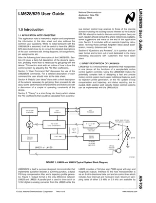
2.0 Device Description
2.1 HARDWARE ARCHITECTURE
Four major functional blocks make up the LM628/629 in
addition to the host and output interfaces. These are the
Trajectory Profile Generator, Loop Compensating PID Filter,
Summing Junction and Motor Position Decoder (Figure 1).
Details of how LM628/629 is implemented by a purpose
designed microcontroller are shown in Figure 2. The control
algorithm is stored in a 1k x 16-bit ROM and uses 16-bit wide
instructions. A PLA decodes these instructions and provides
data transfer timing signals for the single 16-bit data and
instruction bus. User variable filter and trajectory profile pa-
rameters are stored as 32-bit double words in RAM. To
provide sufficient dynamic range a 32-bit position register is
used and for consistency. 32 bits are also used for velocity
and acceleration values. A 32-bit ALU is used to support the
16 x 16-bit multiplications of the error and PID digital filter
coefficients.
2.2 MOTOR POSITION DECODER
LM628/629 provides an interface for an optical position shaft
encoder, decoding the two quadrature output signals to pro-
vide position and direction information, Figure 3. Optionally a
third index position output signal can be used to capture
position once per revolution. Each of the four states of the
quadrature position signal are decoded by the LM628/629
giving a 4 times increase in position resolution over the
number of encoder lines. An “N” line encoder will be decoded
as “4N” position counts by LM628/629.
01101802
FIGURE 2. Hardware Architecture of LM628/629
AN-706
www.national.com 2
3. 2.0 Device Description (Continued)
Position decoder block diagram, Figure 4, shows three lines
coming from the shaft encoder, M1, M2 and Index. From
these the decoder PLA determines if the motor has moved
forward, backward or stayed still and then drives a 16-bit
up-down counter that keeps track of actual motor position.
Once per revolution when all three lines including the index
line are simultaneously low, Figure 3, the current position
count is captured in an index latch.
The 16-bit up-down counter is used to capture the difference
in position from one sample to the next. A position latch
attached to the up-down counter is strobed at the same time
in every sample period by a sync pulse that is generated in
hardware. The position latch is read soon after the sync
pulse and is added to the 32-bit position register in RAM that
holds the actual current position. This is the value that is
subtracted in the summing junction every sample interval
from the new desired position calculated by the trajectory
generator to form the error input to the PID filter.
Maximum encoder state capture rate is determined by the
minimum number of clock cycles it takes to decode each
encoder state, see Figure 3, this minimum number is 8 clock
cycles, capture of the index pulse is also achieved during
these 8 clock cycles. This gives a more than adequate 1
MHz maximum encoder state capture rate with the 8 MHz
fCLK devices (750 kHz for the 6 MHz fCLK devices). For
example, with the 1 MHz capture rate, a motor using a 500
line encoder will be moving at 30,000 rpm.
There is some limited signal conditioning at the decoder
input to remove problems that would occur due to the asyn-
chronous position encoder input being sampled on signal
edges by the synchronous LM628/629. But there is no noise
filtering as such on the encoder lines so it is important that
they are kept clean and away from noise sources.
01101803
FIGURE 3. Quadrature Encoder Output Signals and Direction Decode Table
01101804
FIGURE 4. LM628/629 Motor Position Decoder
AN-706
www.national.com3
4. 2.0 Device Description (Continued)
2.3 TRAJECTORY PROFILE GENERATOR
Desired position inputs to the summing junction, Figure 1,
within the LM628/629 are provided by an internal indepen-
dent trajectory profile generator. The trajectory profile gen-
erator takes information from the host and computes for
each sample interval a new current desired position. The
information required from the host is, operating mode, either
position or velocity, target acceleration, target velocity and
target position in position mode.
2.4 DEFINITIONS RELATING TO PROFILE
GENERATION
The units of position and time, used by the LM628/629, are
counts (4 x N encoder lines) and samples (sample intervals
= 2048/fCLK) respectively. Velocity is therefore calculated in
counts/sample and acceleration in counts/sample/sample.
Definitions of “target”, “desired” and “actual” within the profile
generation activity as they apply to velocity, acceleration and
position are as follows. Final requested values are called
“target”, such as target position. The values computed by the
profile generator each sample interval on the way to the
target value are called “desired”. Real values from the posi-
tion encoder are called “actual”.
For example, the current actual position of the motor will
typically be a few counts away from the current desired
position because a new value for desired position is calcu-
lated every sample interval during profile generation. The
difference between the current desired position and current
actual position relies on the ability of the control loop to keep
the motor on track. In the extreme example of a locked rotor
there could be a large difference between the current actual
and desired positions.
Current desired velocity refers to a fixed velocity at any point
on a on-going trajectory profile. While the profile demands
acceleration, from zero to the target velocity, the velocity will
incrementally increase at each sample interval.
Current actual velocity is determined by taking the difference
in the actual position at the current and the previous sample
intervals. At velocities of many counts per sample this is
reasonably accurate, at low velocities, especially below one
count per sample, it is very inaccurate.
3.0 Profile Generation
Trajectory profiles are plotted in terms of velocity versus
time, Figure 5, and are velocity profiles by reason that a new
desired position is calculated every sample interval. For
constant velocity these desired position increments will be
the same every sample interval, for acceleration and decel-
eration the desired position increments will respectively in-
crease and decrease per sample interval. Target position is
the integral of the velocity profile.
When performing a move the LM628/629 uses the informa-
tion as specified by the host and accelerates until the target
velocity is reached. While doing this it takes note of the
number of counts taken to reach the target velocity. This
number of counts is subtracted from the target position to
determine where deceleration should commence to ensure
the motor stops at the target position. LM628/629 decelera-
tion rates are equal to the acceleration rates. In some cases,
depending on the relative target values of velocity, accelera-
tion and position, the target velocity will not be reached and
deceleration will commence immediately from acceleration.
3.1 TRAJECTORY RESOLUTION
The resolution the motor sees for position is one integral
count. The algorithm used to calculate the trajectory adds
the velocity to the current desired position once per sample
period and produces the next desired position point. In order
to allow very low velocities it is necessary to have velocities
of fractional counts per sample. The LM628/629 in addition
to the 32-bit position range keeps track of 16 bits of fractional
position. The need for fractional velocity counts can be illus-
trated by the following example using a 500 line (2000 count)
encoder and an 8 MHz clock LM628/629 giving a 256 µs
sample interval. If the smallest resolution is 1 count per
sample then the minimum velocity would be 2 revolutions
per second or 120 rpm. (1/2000 revs/count x 1/256 µs
counts/second). Many applications require velocities and
steps in velocity less than this amount. This is provided by
the fractional counts of acceleration and velocity.
3.2 POSITION, VELOCITY AND ACCELERATION
RESOLUTION
Every sample cycle, while the profile demands acceleration,
the acceleration register is added to the velocity register
which in turn is added to the position register. When the
demand for increasing acceleration stops, only velocity is
added to the position register. Only integer values are output
from the position register to the summing junction and so
fractional position counts must accumulate over many
sample intervals before an integer count is added and the
position register changed. Figure 6 shows the position, ve-
locity and acceleration registers.
The position dynamic range is derived from the 32 bits of the
integer position register, Figure 6. The MSB is used for the
direction sign in the conventional manner, the next bit 30 is
used to signify when a position overflow called “wraparound”
has occurred. If the wraparound bit is set (or reset when
01101805
FIGURE 5. Typical Trajectory Velocity Profile
AN-706
www.national.com 4
5. 3.0 Profile Generation (Continued)
going in a negative direction) while in operation the status
byte bit 4 is set and optionally can be used to interrupt the
host. The remaining 30 bits provide the available dynamic
range of position in either the positive or negative direction
(±1,073,741,824 counts).
Velocity has a resolution of 1/216
counts/sample and accel-
eration has a resolution of 1/216
counts/sample/sample as
mentioned above. The dynamic range is 30 bits in both
cases. The loss of one bit is due to velocity and acceleration
being unsigned and another bit is used to detect wrap-
around. This leaves 14 bits or 16,383 integral counts and 16
bits for fractional counts.
3.3 VELOCITY MODE
LM628 supports a velocity mode where the motor is com-
manded to continue at a specified velocity, until it is told to
stop (LTRJ bits 9 or 10). The average velocity will be as
specified but the instantaneous velocity will vary. Velocities
of fractional counts per sample will exhibit the poorest in-
stantaneous velocity. Velocity mode is a subset of position
mode where the position is continually updated and moved
ahead of the motor without a specified stop position. Care
should be exercised in the case where a rotor becomes
locked while in velocity mode as the profile generator will
continue to advance the position. When the rotor becomes
free high velocities will be attained to catch-up with the
current desired position.
3.4 MOTOR OUTPUT PORT
LM628 output port is configured to 8 bits after reset. The
8-bit output is updated once per sample interval and held
until it is updated during the next sample interval. This allows
use of a DAC without a latch. For 12-bit operation the
PORT12 command should be issued immediately after re-
set. The output is multiplexed in two 6-bit words using pins
18 through 23. Pin 24 is low for the least significant word and
high for the most significant. The rising edge of the active low
strobe from pin 25 should be used to strobe the output into
an external latch, see Figure 7. The DAC output is offset
binary code, the zero codes are hex'80' for 8 bits and
hex'800' for 12 bits.
The choice of output resolution is dependant on the user’s
application. There is a fundamental trade-off between sam-
pling rate and DAC output resolution, the LM628 8-bit output
at a 256 µs sampling interval will most often provide as good
results as a slower, e.g. microcontroller, implementation
which has a 4 ms typical sampling interval and uses a 12-bit
output. The LM628 also gives the choice of a 12-bit DAC
output at a 256 µs sampling interval for high precision appli-
cations.
LM629 PWM sign and magnitude signals are output from
pins 18 and 19 respectively. The sign output is used to
control motor direction. The PWM magnitude output has a
resolution of 8 bits from maximum negative drive to maxi-
mum positive drive. The magnitude output has an off condi-
tion, with the output at logic low, which is useful for turning a
motor off when using a bridge motor drive circuit. The mini-
mum duty cycle is 1/128 increasing to a maximum of 127/
128 in the positive direction and a maximum of 128/128 in
the negative direcition, i.e., a continuous output. There are
four PWM periods in one LM629 sample interval. With an 8
MHz clock this increases the PWM output rate to 15.6 kHz
from the LM629 maximum 3.9 kHz sample rate, see Figure 8
for further timing information.
01101806
FIGURE 6. Position, Velocity and Acceleration
Registers
01101807
FIGURE 7. LM628 12-Bit DAC Output Multiplexed
Timing
AN-706
www.national.com5
6. 3.0 Profile Generation (Continued)
3.5 HOST INTERFACE
LM628/629 has three internal registers: status, high, and low
bytes, Figure 9, which are used to communicate with the
host microcontroller. These are controlled by the RD, WR,
and PS lines and by use of the busy bit of the status byte.
The status byte is read by bringing RD and PS low, bit 0 is
the busy bit. Commands are written by bringing WR and PS
low. When PS is high, WRbrought low writes data into
LM628/629 and similarly, RD is brought low to read data
from LM628/629. Data transfer is a two-byte operation writ-
ten in most to least significant byte order. The above descrip-
tion assumes that CS is low.
3.6 HARDWARE BUSY BIT OPERATION
Before and between all command byte and data byte pair
transfers, the busy bit must be read and checked to be at
logic low. If the busy bit is set and commands are issued they
will be ignored and if data is read it will be the current
contents of the I/O buffer and not the expected data. The
busy bit is set after the rising edge of the write signal for
commands and the second rising edge of the respective
read or write signal for two byte data transfers, Figure 10.
The busy bit remains high for approximately 15 µs.
01101808
Note: Sign output (pin 18) not shown.
FIGURE 8. LM629 PWM Output Signal Format
01101809
FIGURE 9. Host Interface Internal I/O Registers
AN-706
www.national.com 6
7. 3.0 Profile Generation (Continued)
The busy bit reset to logic low indicates that high and low
byte registers shown in Figure 9 have been either loaded or
read by the LM628/629 internal microcode. To service the
command or data transfer this microcode which performs the
trajectory and filter calculations is interrupted, except in criti-
cal areas, and the on-going calculation is suspended. The
microcode was designed this way to achieve minimum la-
tency when communicating with the host. However, if this
communication becomes too frequent and on-going calcula-
tions are interrupted too often corruption will occur. In a
256 µs sample interval, the filter calculation takes 50 µs,
outputting a sample 10 µs and trajectory calculation 90 µs. If
the LM628 behaves in a manner that is unexpected the host
communication rate should be checked in relation to these
timings.
3.7 FILTER INITIAL VALUES AND TUNING
When connecting up a system for the first time there may be
a possibility that the loop phasing is incorrect. As this may
cause violent oscillation it is advisable to initially use a very
low value of proportional gain, say kp = 1 (with kd, ki and il all
set to zero), which will provide a weak level of drive to the
motor. (The Start command, STT, is sent to LM628/629 to
close the control loop and energize the motor.) If the system
does oscillate with this low value of kp then the motor con-
nections should be reversed.
Having determined that the loop phasing is correct kp can be
increased to a value of about 20 to see that the control
system basically works. This value of kp should hold the
motor shaft reasonably stiffly, returning the motor to the set
position, which will be zero until trajectory values have been
input and a position move performed. If oscillation or unac-
ceptable ringing occurs with a kp value of 20 reduce this until
it stops. Low values of acceleration and velocity can now be
input, of around 100, and a position move commanded to
say 1000 counts. All values suggested here are decimal. For
details of loading trajectory and filter parameters see Section
3.0, reference (5) and the data sheet.
It is useful at this stage to try different values of acceleration
and velocity to get a feel for the system limitations. These
can be determined by using the reporting commands of
desired and actual position and velocity, to see if the error
between desired and actual positions of the motor are con-
stant and not increasing without bound. See Section 3.6 and
the data sheet for information about the reporting com-
mands. Clearly it will be difficult to tune for best system
response if the motor and its load cannot achieve the de-
manded values of acceleration and velocity. When correct
operation is confirmed and limiting values understood, filter
tuning can commence.
Due to the basic difficulty of accurately modeling a control
system, with the added problem of variations that can occur
in mechanical components over time and temperature, it is
always necessary at some stage to perform tuning empiri-
cally. Determining the PID filter coefficients by tuning is the
preferred method with LM628/629 because of the inherent
flexibility in changing the filter coefficients provided by this
programmable device.
Before tuning a control system the effect of each of the PID
filter coefficients should be understood. The following is a
very brief review, for a detailed understanding reference (2)
should be consulted. The proportional coefficient, kp, pro-
vides adjustment of the control system loop proportional
gain, as this is increased the output steady state error is
reduced. The error between the required and actual position
is effectively divided by the loop gain. However there is a
natural limitation on how far kp can be increased on its own
to reduce output position error because a reduction in phase
margin is also a consequence of increasing kp. This is first
encountered as ringing about the final position in response
to a step change input and then instability in the form of
oscillation as the phase margin becomes zero. To improve
stability, kd, the derivative coefficient, provides a damping
effect by providing a term proportional to velocity in an-
01101810
FIGURE 10. Busy Bit Operation during Command and Data Write Sequence
AN-706
www.national.com7
8. 3.0 Profile Generation (Continued)
tiphase to the ringing, or viewed in another way, adds some
leading phase shift into the loop and increases the phase
margin.
In the tuning process the coefficients kp and kd are iteratively
increased to their optimum values constrained by the system
constants and are trade-offs between response time, stabil-
ity and final position error. When kp and kd have been
determined the integral coefficient, ki, can be introduced to
remove steady state errors at the load. The steady state
errors removed are the velocity lag that occurs with a con-
stant velocity output and the position error due to a constant
static torque. A value of integration limit, il, has to be input
with ki, otherwise ki will have no effect. The integral coeffi-
cient ki adds another variable to the system to allow further
optimization, very high values of ki will decrease the phase
margin and hence stability, see Section 5 and reference (2)
for more details. Reference (5) gives more details of PID
filter tuning and how to load filter parameters.
Figure 11 illustrates how a relatively slow response with
overshoot can be compensated by adjustment of the PID
filter coefficients to give a faster critically damped response.
4.0 User Command Set
4.1 OVERVIEW
The following types of User Commands are available:
Initialization
Filter control commands
Trajectory control commands
Interrupt control commands
Data reporting commands
User commands are single bytes and have a varying number
of accompanying data bytes ranging from zero to fourteen
depending upon the command. Both filter and trajectory
control commands use a double buffered scheme to input
data. These commands load primary registers with multiple
words of data which are only transferred into secondary
working registers when the host issues a respective single
byte user command. This allows data to be input before its
actual use which can eliminate any potential communication
bottlenecks and allow synchronized operation of multiple
axes.
4.2 HOST-LM628/629 COMMUNICATION—THE BUSY
BIT
Communication flow between the LM628/629 and its host is
controlled by using a busy bit, bit 0, in the Status Byte. The
busy bit must be checked to be at logic 0 by the host before
commands and data are issued or data is read. This includes
between data byte pairs for commands with multiple words
of data.
4.3 LOADING THE TRAPEZOIDAL VELOCITY PROFILE
GENERATOR
To initiate a motor move, trajectory generator values have to
be input to the LM628/629 using the Load Trajectory Param-
eters, LTRJ, command. The command is followed by a tra-
jectory control word which details the information to be
loaded in subsequent data words. Table 1 gives the bit
allocations, a bit is set to logic 1 to give the function shown.
TABLE 1. Trajectory Control Word Bit Allocations
Bit Position Function
Bit 15 Not Used
Bit 14 Not Used
Bit 13 Not Used
Bit 12 Forward Direction (Velocity Mode Only)
Bit 11 Velocity Mode
Bit 10 Stop Smoothly (Decelerate as
Programmed)
Bit 9 Stop Abruptly (Maximum Deceleration)
Bit 8 Turn Off Motor (Output Zero Drive)
Bit 7 Not Used
Bit 6 Not Used
Bit 5 Acceleration Will Be Loaded
Bit 4 Acceleration Data Is Relative
Bit 3 Velocity Will Be Loaded
Bit 2 Velocity Data Is Relative
Bit 1 Position Will Be Loaded
Bit 0 Position Data Is Relative
Bits 0 to 5 determine whether any, all or none of the position,
velocity or acceleration values are loaded and whether they
are absolute values or values relative to those previously
loaded. All trajectory values are 32-bit values, position val-
ues are both positive and negative. Velocity and acceleration
are 16-bit integers with 16-bit fractions whose absolute value
is always positive. When entering relative values ensure that
the absolute value remains positive. The manual stop com-
mands bits 8, 9 and 10 are intended to allow an unpro-
grammed stop in position mode, while a position move is in
progress, perhaps by the demand of some external event,
and to provide a method to stop in velocity mode. They do
not specify how the motor will stop in position mode at the
end of a normal position move. In position mode a pro-
grammed move will automatically stop with a deceleration
rate equal to the acceleration rate at the target position.
Setting a stop bit along with other trajectory parameters at
the beginning of a move will result in no movement! Bits 8, 9
and 10 should only be set one at a time, bit 8 turns the motor
off by outputting zero drive to the motor, bit 9 stops the motor
at maximum deceleration by setting the target position equal
to the current position and bit 10 stops the motor using the
current user-programmed acceleration value. Bit 11 is set for
operating in velocity mode and bit 12 is set for forward
direction in velocity mode.
AN-706
www.national.com 8
9. 4.0 User Command Set (Continued)
Following immediately after the trajectory control word
should be two 16-bit data words for each parameter speci-
fied to be loaded. These should be in the descending order
of the trajectory control word bits, that is acceleration, veloc-
ity and position. They are written to the LM628/629 as two
pairs of data bytes in most to least significant byte order. The
busy bit should be checked between the command byte and
the data byte pair forming the trajectory control word and the
individual data byte pairs of the data. The Start command,
STT, transfers the loaded trajectory data into the working
registers of the double buffered scheme to initiate movement
of the motor. This buffering allows any parameter, except
acceleration, to be updated while the motor is moving by
loading data with the LTRJ command and to be later ex-
ecuted by using the STT command.
New values of acceleration can be loaded with LTRJ while
the motor is moving, but cannot be executed by the STT
command until the trajectory has completed or the drive to
the motor is turned off by using bit 8 of the trajectory control
word. If acceleration has been changed and STT is issued
while the drive to the motor is still present, a command error
interrupt will be generated and the command ignored. Sepa-
rate pairs of LTRJ and STT commands should be issued to
first turn the motor off and then update acceleration. System
operation when changing acceleration while the motor is
moving, but with the drive removed, is discussed in Section
4.5.1.
4.4 LOADING PID FILTER COEFFICIENTS
PID filter coefficients are loaded using the Load Filter Pa-
rameters, LFIL, command and are the proportional coeffi-
cient kp, derivative coefficient kd and integral coefficient ki.
Associated with ki, an integration limit, il, has to be loaded.
This constrains the magnitude of the integration term of the
PID filter to the il value, see Section 4.4.2. Associated with
the derivative coefficient, a derivative sample rate can be
chosen from 2048/fCLK to (2048 x 256)/f CLK in steps of
2048/fCLK, see Section 4.4.1.
The first pair of data bytes following the LFIL command byte
form the filter control word. The most significant byte sets the
derivative sample rate, the fastest rate, 2048/fCLK, being
hex'00' the slowest rate (2048 x 256)/fCLK being hex'FF'. The
lower four bits of the least significant byte tell the LM628/629
which of the coefficients is going to be loaded, bit 3 is kp, bit
2 is ki, bit 1 is kd and bit 0 is il. Each filter coefficient and the
integration limit can range in value from hex'0000' to '7FFF',
positive only. If all coefficient values are loaded then ten
bytes of data, including the filter control word, will follow the
LFIL command. Again the busy bit has to be checked be-
tween the command byte and filter control word and be-
tween data byte pairs. Use of new filter coefficient values by
the LM628/629 is initiated by issuing the single byte Update
Filter command, UDF.
When controlled movement of the motor has been achieved,
by programming the filter and trajectory, attention turns to
incorporating the LM628/629 into a system. Interrupt Control
Commands and Data Reporting Commands enable the host
microcontroller to keep track of LM628/629 activity.
4.5 INTERRUPT CONTROL COMMANDS
There are five commands that can be used to interrupt the
host microcontroller when a predefined condition occurs and
two commands that control interrupt operation. When the
LM628/629 is programmed to interrupt its host, the event
which caused this interrupt can be determined from bits 1 to
6 of the Status Byte (additionally bit 0 is the busy bit and bit
7 indicates that the motor is off). All the Interrupt Control
commands are executable during motion.
The Mask Interrupts command, MSKI, is used to tell LM628/
629 which of bits 1 to 6 will interrupt the host through use of
interrupt mask data associated with the command. The data
is in the form of a data byte pair, bits 1–6 of the least
significant byte being set to logic 1 when an interrupt source
is enabled. The Reset Interrupts command, RSTI, resets
interrupt bits in the Status Byte by sending a data byte pair,
the least significant byte having logic 0 in bit positions 1 to 6
if they are to be reset.
Executing the Set Index Position command, SIP, causes bit
3 of the status byte to be set when the absolute position of
the next index pulse is recorded in the index register. This
can be read with the command, Read Index Position, RDIP.
Executing either Load Position Error for Interrupt, LPEI, or
Load Position Error for Stopping, LPES, commands, sets bit
5 of the Status Byte when a position error exceeding a
specified limit occurs. An excessive position error can indi-
cate a serious system problem and these two commands
give the option when this occurs of either interrupting the
Underdamped Critically Damped
01101821 01101822
FIGURE 11. Position vs Time for 100 Count Step Input
AN-706
www.national.com9
10. 4.0 User Command Set (Continued)
host or stopping the motor and interrupting the host. The
excessive position is specified following each command by a
data byte pair in most to least significant byte order.
Executing either Set Break Point Absolute, SBPA, or Set
Break Point Relative, SBPR, commands, sets bit 6 of the
status byte when either the specified, absolute or relative,
breakpoint respectively is reached. The data for SBPA can
be the full position range (hex'C0000000' to '3FFFFFFF')
and is sent in two data byte pairs in most to least significant
byte order. The data for the Set Breakpoint Relative com-
mand is also of two data byte pairs, but its value should be
such that when added to the target position it remains within
the absolute position range. These commands can be used
to signal the moment to update the on-going trajectory or
filter coefficients. This is achieved by transferring data from
the primary registers, previously loaded using LTRJ or LFIL,
to working registers, using the STT or UDF commands.
Interrupt bits 1, 2 and 4 of the Status Byte are not set by
executing interrupt commands but by events occurring dur-
ing LM628/629 operation as follows. Bit 1 is the command
error interrupt, bit 2 is the trajectory complete interrupt and
bit 4 is the wraparound interrupt. These bits are also masked
and reset by the MSKI and RSTI commands respectively.
The Status Byte still indicates the condition of interrupt bits
1–6 when they are masked from interrupting the host, allow-
ing them to be incorporated in a polling scheme.
4.6 DATA REPORTING COMMANDS
Read Status Byte, RDSTAT, supported by a hardware regis-
ter accessed via CS, RD and PS control, is the most fre-
quently used method of determining LM628/629 status. This
is primarily to read the busy bit 0 while communicating
commands and data as described in Section 3.2.
There are seven other user commands which can read data
from LM628/629 data registers.
The Read Signals Register command, RDSIGS, returns a
16-bit data word to the host. The least-significant byte re-
peats the RDSTAT byte except for bit 0 which indicates that
a SIP command has been executed but that an index pulse
has not occurred. The most significant byte has 6 bits that
indicate set-up conditions (bits 8, 9, 11, 12, 13 and 14). The
other two bits of the RDSIGS data word indicate that the
trajectory generator has completed its function, bit 10, and
that the host interrupt output (Pin 17) has been set to logic 1,
bit 15. Full details of the bit assignments of this command
can be found in the data sheet.
The Read Index Position, RDIP, command reads the position
recorded in the 32 bits of the index register in four data
bytes. This command, with the SIP command, can be used
to acquire a home position or successive values. These
could be used, for example, for gross error checking.
Both on-going 32-bit position inputs to the summing junction
can be read. Read desired position, RDDP, reads the current
desired position the demand or “set point input” from the
trajectory generator and Read Real Position, RDRP, reads
the current actual position of the motor.
Read Desired Velocity, RDDV, reads the current desired
velocity used to calculate the desired position profile by the
trajectory generator. It is a 32-bit value containing integer
and fractional velocity information. Read Real Velocity,
RDRV, reads the instantaneous actual velocity and is a
16-bit integer value.
Read Integration-Term Summation Value, RDSUM, reads
the accumulated value of the integration term. This is a
16-bit value ranging from zero to the current, il, integration
limit value.
4.7 SOFTWARE EXAMPLE
The following example shows the flow of microcontroller
commands needed to get the LM628/629 to control a simple
motor move. As it is non-specific to any microcontroller
pseudo commands WR,XXXXH and RD,XXXXH with hex
immediate data will be used to indicate read and write op-
erations respectively by the host to and from the LM628/629.
Decisions use IF..THEN..ELSE. BUSY is a user routine to
check the busy bit in the Status Byte, WAIT is a user routine
to wait 1.5 ms after hardware reset.
LABEL MNEMONIC :REMARK
Initialization:
WAIT :Routine to wait 1.5 ms after reset.
RDSTAT :Check correct RESET operation by reading the
:Status Byte. This should be either hex’84’ or ’C4’
IF Status byte not equal hex’84’ or ’C4’ THEN repeat
hardware RESET
:Make decision concerning validity of RESET
Optionally the Reset can be further checked for correct operation as follows. It is useful to include this to reset all interrupt bits
in the Status Byte before further action:
MSKI :Mask interrupts
BUSY :Check busy bit 0 routine
WR, 0000H :Host writes two zero bytes of data to
:LM628/629. This mask disables all interrupts.
BUSY :Check busy bit
RSTI :Reset Interrupts command
BUSY :Check busy bit
WR, 0000H :Host writes two zero bytes of data to LM628/629
RDSTAT :Status byte should read either hex’80’ or ’C0’
IF Status Byte not equal hex’80’ or ’C0’ THEN repeat
hardware RESET
:
IF Status Byte equal to hex’C0’ THEN continue ELSE PORT
:
BUSY :Check busy bit
AN-706
www.national.com 10
11. 4.0 User Command Set (Continued)
RSTI :Reset Interrupts
BUSY :Check busy bit
WR, 0000H :Reset all interrupt bits
Set Output Port Size for a 12-bit DAC.
PORT BUSY :Check busy bit
PORT12 :Sets LM628 output port to 12-bits
(Only for systems with 12-bit DAC)
Load Filter Parameters
BUSY :Check busy bit
LFIL :Load Filter Parameters command
BUSY :Check busy bit
WR, 0008H :Filter Control Word
: Bits 8 to 15 (MSB) set the derivative
:sample rate.
: Bit 3 Loading kp data
: Bit 2 Loading ki data
: Bit 1 Loading kd data
: Bit 0 Loading il data
:Choose to load kp only at maximum
:derivative sample rate then Filter Control
:Word = 0008H
BUSY :Check busy bit
WR, 0032H :Choose kp = 50, load data byte pair MS
:byte first
Update Filter
BUSY :Check busy bit
UDF :
Load Trajectory Parameters
BUSY :Check busy bit
LTRJ :Load trajectory parameters command.
BUSY :Check busy bit
WR, 002AH :Load trajectory control word:
: See Table I
:Choose Position mode, and load absolute
:acceleration, velocity and position. Then
:trajectory control word = 002AH. This means
:6 pairs of data bytes should follow.
BUSY :Check busy bit
WR, XXXXH :Load Acceleration integer word MS byte first
BUSY :Check busy bit
WR, XXXXH :Load Acceleration fractional word MS byte first
BUSY :Check busy bit
WR, XXXXH :Load Velocity integer word MS byte first
BUSY :Check busy bit
WR, XXXXH :Load Velocity fractional word MS byte first
BUSY :Check busy bit
WR, XXXXH :Load Position MS byte pair first
BUSY :Check busy bit
WR, XXXXH :Load position LS byte pair
Start Motion
BUSY :Check busy bit
STT :Start command
Check for Trajectory complete.
RDSTAT :Check Status Byte bit 2 for trajectory
:complete
Busy bit check routine
BUSY RDSTAT :Read status byte
If bit 0 is set THEN BUSY ELSE RETURN
END
*Consult reference (5) for more information on programming the LM628/629.
AN-706
www.national.com11
12. 4.0 User Command Set (Continued)
5.0 Helpful User Ideas
5.1 GETTING STARTED
This section outlines the actions that are necessary to imple-
ment a simple motion control system using LM628/629.
More details on how LM628/629 works and the use of the
User Command Set are given in the sections “2.0 DEVICE
DESCRIPTION” and “3.0 USER COMMAND SET”.
5.2 HARDWARE
The following hardware connections need to be made:
5.2.1 Host Microcontroller Interface
Interface to the host microcontroller is via an 8-bit command/
data port which is controlled by four lines. These are the
conventional chip select CS, read RD, write WR and a line
called Port Select PS, see Figure 13. PS is used to select
01101812
FIGURE 12. Basic Software Flow
AN-706
www.national.com 12
13. 5.0 Helpful User Ideas (Continued)
user Command or Data transfer between the LM628/629
and the host. In the special case of the Status Byte
(RDSTAT) bringing PS, CS and RD low together allows
access to this hardware register at any time. An optional
interrupt line, HI, from the LM628/629 to the host can be
used. A microcontroller output line is necessary to control the
LM628/629 hardware reset action.
5.2.2 Position Encoder Interface
The two optical incremental position encoder outputs feed
into the LM628/629 quadrature decoder TTL inputs A and B.
The leading phase of the quadrature encoder output defines
the forward direction of the motor and should be connected
to input A. Optionally an index pulse may be used from the
position encoder. This is connected to the IN input, which
should be tied high if not used, see Figure 13.
5.2.3 Output Interface
LM628 has a parallel output of either 8 or 12 bits, the latter is
output as two multiplexed 6-bit words. Figure 14 illustrates
how a motor might be driven using a LM12 power linear
amplifier from the output of 8-bit DAC0800.
LM629 has a sign and magnitude PWM output, Figure 13, of
7-bit resolution plus sign. Figure 15 shows how the LM629
sign and magnitude outputs can be used to control the
outputs of an LM18293 quad half-H driver. The half-H drivers
are used in pairs, by using 100 mΩ current sharing resistors,
and form a full-H bridge driver of 2A output. The sign bit is
used to steer the PWM LM629 magnitude output to either
side of the H-bridge lower output transistors while holding
the upper transistors on the opposite side of the H-bridge
continuously on.
01101813
FIGURE 13. LM628 and LM629 Host, Output and Position Encoder Interfaces
01101814
FIGURE 14. LM628 Example of Linear Motor Drive Using LM12
AN-706
www.national.com13
14. 5.0 Helpful User Ideas (Continued)
5.3 SOFTWARE
Making LM628/629 perform a motion control function re-
quires that the host microcontroller, after initializing LM628/
629, loads coefficients for the PID filter and then loads
trajectory information. The interrupt and data reporting com-
mands can then be used by the host to keep track of
LM628/629 actions. For detailed descriptions see the
LM628/629 data sheet and Section 3.
5.4 INITIALIZATION
There is only one initialization operation that must be per-
formed; a check that hardware reset has operated correctly.
If required, the size of the LM628 output port should be
configured. Other operations which might be part of user’s
system initialization are discussed under Interrupt and Data
Reporting commands, Sections 3.5 and 3.6.
5.4.1 Initializing LM628 Output Port
Reset sets the LM628 output port size to 8 bits. If a 12-bit
DAC is being used, then the output port size is set by the use
of the PORT12 command.
5.4.2 Hardware RESET Check
The hardware reset is activated by a logic low pulse at pin
27, RST, from the host of greater than 8 clock cycles. To
ensure that this reset has operated correctly the Status Byte
should be checked immediately after the reset pin goes high,
it should read hex'00'. If the reset is successful this will
change to hex'84' or 'C4' within 1.5 ms. If not, the hardware
reset and check should be repeated. A further check can be
used to make certain that a reset has been successful by
using the Reset Interrupts command, RSTI. Before sending
the RSTI, issue the Mask Interrupts command, MSKI, and
mask data that disables all interrupts, this mask is sent as
two bytes of data equaling hex'0000'. Then issue the RSTI
command plus mask data that resets all interrupts, this
equals hex'0000' and is again sent as two bytes. Do not
forget to check the busy bit between the command byte and
data byte pairs. When the chip has reset properly the status
byte will change from hex'84' or 'C4' to hex'80' or 'C0'.
5.4.3 Interrupt Commands
Optionally the commands which cause the LM628/629 to
take action on a predefined condition (e.g., SIP, LPEI, LPES,
SBPA and SBPR) can be included in the initialization, these
are discussed under Interrupt Commands.
5.5 PERFORMANCE REFINEMENTS
5.5.1 Derivative Sample Rate
The derivative sample interval is controllable to improve the
stability of low velocity, high inertia loads. At low speeds,
when fractional counts for velocity are used, the integer
position counts, desired and actual, only change after sev-
eral sample intervals of the LM628/629 (2048/fCLK ). This
means that for sample intervals between integer count
changes the error voltage will not change for successive
samples. As the derivative term, kd, multiplies the difference
betweeen the previous and current error values, if the de-
rivative sample interval is the same as the sample interval,
several consecutive sample intervals will have zero deriva-
tive term and hence no damping contribution. Lengthening
the derivative sample interval ensures a more constant de-
rivate term and hence improved stability. Derivative sample
interval is loaded with the filter coefficient values as the most
significant byte of the LFIL control word everytime the com-
mand is used, the host therefore needs to store the current
value for re-loading at times of filter coefficient change.
5.5.2 Integral Windup
Along with the integral filter coefficient, ki, an integration limit,
il, has to be input into LM628/629 which allows the user to
set the maximum value of the integration term of equation
(3), Section 5.2.2. This term is then able to accumulate up to
01101815
FIGURE 15. LM629 H-Bridge Motor Drive Example Using LM18293
AN-706
www.national.com 14
15. 5.0 Helpful User Ideas (Continued)
the value of the integration limit and any further increase due
to error of the same sign is ignored. Setting the integration
limit enables the user to prevent an effect called “Integral
Windup”. For example, if an LM628/629 attempts to accel-
erate a motor at a faster rate than it can achieve, a very large
integral term will result. When the LM628/629 tries to stop
the motor at the target position the large accumulated inte-
gral term will dominate the filter and cause the motor to badly
overshoot, and thus integral windup has occurred.
5.5.3 Profiles Other Than Trapezoidal
If it is required to have a velocity profile other than trapezoi-
dal, this can be accomplished by breaking the profile into
small pieces each of which is part of a small trapezoid. A
piecewise linear approximation to the required profile can
then be achieved by changing the maximum velocity before
the trapezoid has had time to complete, see Figure 16.
5.5.4 Synchronizing Axes
For controlling tightly coupled coordinated motion between
multiple-axes, synchronization is required. The best possible
synchronization that can be achieved between multiple
LM628/629 is within one sample interval, (2048/fCLK, 256 µs
for an 8 MHz clock, 341 µs for a 6 MHz clock). This is
achieved by using the pipeline feature of the LM628/629
where all controlled axes are loaded individually with trajec-
tory values using the LTRJ command and then simulta-
neously given the start command STT. PID filter coefficients
can be updated in a similar manner using LFIL and UDF
commands.
5.6 OPERATING CONSTRAINTS
5.6.1 Updating Acceleration on the Fly
Whereas velocity and target position can be updated while
the motor is moving, on the “fly”, the algorithm described in
Section 2.5 prevents this for acceleration. To change accel-
eration while the motor is moving in mid-trajectory the motor
off command has to be issued by setting LTRJ command bit
8. Then the new acceleration can be loaded, again using the
LTRJ command. When the start command STT is issued the
motor will be energized and the trajectory generator will start
generating a new profile from the actual position when the
STT command was issued. In doing this the trajectory gen-
erator will assume that the motor starts from a stationary
position in the normal way. If the motor has sufficient inertia
and is still moving when the STT command is issued then
the control loop will attempt to bring the motor on to the new
profile, possibly with a large error value being input to the
PID filter and a consequential saturated output until the
motor velocity matches the profile. This is a classic case of
overload in a feedback system. It will operate in an open loop
manner until the error input gets within controllable bounds
and then the feedback loop will close. Performance in this
situation is unpredictable and application specific. LM628/
629 was not intentionally designed to operate in this way.
5.6.2 Command Update Rate
If an LM628/629 is updated too frequently by the host it will
not keep up with the commands given. The LM628/629
aborts the current trajectory calculation when it receives a
new STT command, resulting in the output staying at the
value of the previous sample. For this reason it is recom-
mended that trajectory is not updated at a greater rate than
once every 10 ms.
6.0 Theory
6.1 PID FILTER
6.1.1 PID Filter in the Continuous Domain
The LM628/629 uses a PID filter as the loop compensator,
the expression for the PID filter in the continuous domain is:
H(s) = Kp + Ki /s + Kds (1)
Where Kp = proportional coefficient
Ki = integral coefficient
Kd = derivative coefficient
01101816
FIGURE 16. Generating a Non-Trapezoidal Profile
AN-706
www.national.com15
16. 6.0 Theory (Continued)
6.1.2 PID Filter Bode Plots
The Bode plots for this function (shown in Figure 17) show
the effect of the individual terms of Equation (1). The propor-
tional term, Kp provides adjustment of proportional gain. The
derivative term Kd increases the system bandwidth but more
importantly adds leading phase shift to the control loop at
high frequencies. This improves stability by counteracting
the lagging phase shift introduced by other control loop
components such as the motor. The integral term, K i, pro-
vides a high DC gain which reduces static errors, but intro-
duces a lagging phase shift at low frequencies. The relative
magnitudes of K d, Ki and loop proportional gain have to be
adjusted to achieve optimum performance without introduc-
ing instability.
6.2 PID FILTER COEFFICIENT SCALING FACTORS FOR
LM628/629
While the easiest way to determine the PID filter coefficient
kp, kd, and ki values is to use tuning as described in Section
2.11, some users may want to use a more theoretical ap-
proach to at least find initial starting values before fine tun-
ing. As very often this analysis is performed in the continu-
ous (s) domain and transformed into the discrete digital
domain for implementation, the relationship between the
continuous domain coefficients and the values input into
LM628/629 is of interest.
01101817
FIGURE 17. Bode Plots of PID Transfer Function
AN-706
www.national.com 16
17. 6.0 Theory (Continued)
6.2.1 PID Filter Difference Equation
In the discrete domain, Equation (1) becomes the difference
equation:
(2)
Where:
T is the sample interval 2048/fCLK
Ts is the derivative sample interval (2048/f CLK x (1..255)
6.2.2 Difference Equation with LM628/629 Coefficients
In terms of LM628/629 coefficients, Equation (2) becomes:
(3)
Where:
kp, ki and kd are the discrete-time LM628/629 coefficients
e(n) is the position error at sample time n
n' indicates sampling at the derivative sampling rate.
The error signal e(n) [or e(n')] is a 16-bit number from the
output of the summing junction and is the input to the PID
filter. The 15-bit filter coefficients are respectively multiplied
by the 16-bit error terms as shown in Equation (3)A to
produce 32-bit products.
6.2.3 LM628/629 PID Filter Output
The proportional coefficient kp is multiplied by the error sig-
nal directly. The error signal is continually summed at the
sample rate to previously accumulated errors to form the
integral signal and is maintained to 24 bits. To achieve a
more usable range from this term, only the most significant
16 bits are used and multiplied by the integral coefficient, ki.
The absolute value of this product is compared with the
integration limit, il, and the smallest value, appropriately
signed, is used. To form the derivative signal, the previous
error is subtracted from the current error over the derivative
sampling interval. This is multiplied by the derivative coeffi-
cient k d and the product contributes every sample interval to
the output independently of the user chosen derivative
sample interval.
The least significant 16 bits of the 32-bit products from the
three terms are added together to produce the resulting u(n)
of Equation (3) each sample interval. From the PID filter
16-bit result, either the most significant 8 or 12 bits are
output, depending on the output word size being used. A
consequence of this and the use of the 16 MSB’s of the
integral signal is a scaling of the filter coefficients in relation
to the continuous domain coefficients.
6.2.4 Scaling for kp and k d
Figure 18 gives details of the multiplication and output for kp
and kd. Taking the output from the MS byte of the LS 16 bits
of the 32-bit result register causes an effective 8-bit
right-shift or division of 256 associated with kp and kd as
follows:
Result = kp x e(n)/256 = Kpx e(n) .'. kp
= 256 x Kp.
Similarly for kd:
Result = (kd x [e(n') − e(n'−1)])/256
= Kd/Ts x e(n) .'. k d = 256 x Kd/Ts
Where Ts is the derivative sampling rate.
6.2.5 Scaling for ki
Figure 19 shows the multiplication and output for the integral
term ki. The use of a 24-bit register for the error terms
summation gives further scaling:
Result = ki/256 x > e(n)/256
= Ki x T .'. ki = 65536 Ki x T.
Where T is the sampling interval 2048/fCLK.
For a 12-bit output the factors are:
kp = 16 x Kp, kd = 16 x Kd/Ts and ki = 4096 K i x T.
If the 32-bit result register overflows into the most significant
16-bits as a result of a calculation, then all the lower bits are
set high to give a predictable saturated output.
6.3 AN EXAMPLE OF A TRAJECTORY CALCULATION
Problem: Determine the trajectory parameters for a motor
move of 500 revolutions in 1 minute with 15 seconds of
acceleration and deceleration respectively. Assume the op-
tical incremental encoder used has 500 lines.
The LM628/629 quadrature decoder gives four counts for
each encoder line giving 2000 counts per revolution in this
example. The total number of counts for this position move is
2000 x 500 = 1,000,000 counts.
By definition, average velocity during the acceleration and
deceleration periods, from and to zero, is half the maximum
01101818
FIGURE 18. Scaling of kp and kd
AN-706
www.national.com17
18. 6.0 Theory (Continued)
velocity. In this example, half the total time to make the move
(30 seconds) is taken by acceleration and deceleration. Thus
in terms of time, half the move is made at maximum velocity
and half the move at an average velocity of half this maxi-
mum. Therefore, the combined distance traveled during ac-
celeration and deceleration is half that during maximum
velocity or 1⁄3 of the total, or 333,333 counts. Acceleration
and deceleration takes 166,667 counts respectively.
The time interval used by the LM628/629 is the sample
interval which is 256 µs for a fCLK of 8 MHz.
The number of sample periods in 15 seconds = 15s/ 256 µs
= 58,600 samples
Remembering that distance s = at2
/2 is traveled due to
acceleration 'a' and time 't'.
Therefore acceleration a = 2S/t2
= 2 x 166,667/58,600
= 97.1 x 10⁻⁶
counts/sample 2
Acceleration and velocity values are entered into LM628/629
as a 32-bit integer double-word but represents a 16-bit inte-
ger plus 16-bit fractional value. To achieve this acceleration
and velocity decimal values are scaled by 65536 and any
remaining fractions discarded. This value is then converted
to hex to enter into LM628 in four bytes.
Scaled acceleration a = 97.1 x 10−6
x 65536
= 6.36 decimal = 00000006 hex.
The maximum velocity can be calculated in two ways, either
by the distance in counts traveled at maximum velocity
divided by the number of samples or by the acceleration
multiplied by the number of samples over acceleration dura-
tion, as follows:
Velocity = 666,667/117,200 = 97.1 x 10−6
x 58,600
= 5.69 counts/sample
Scaled by 65536 becomes 372,899.8 decimal = 0005B0A3
hex.
Inputting these values for acceleration and velocity with the
target position of 1,000,000 decimal, 000F4240 hex will
achieve the desired velocity profile.
7.0 Questions and Answers
7.1 THE TWO MOST POPULAR QUESTIONS
Why doesn’t the motor move, I’ve loaded filter param-
eters, trajectory parameters and issued Update Filter,
UDF, and Start, STT, commands?
Answer: The most like cause is that a stop bit (one of bits 8,
9 or 10 of the trajectory control word) has been set in error,
01101819
FIGURE 19. Scaling for ki
01101820
FIGURE 20. Trajectory Calculation Example Profile
AN-706
www.national.com 18
19. 7.0 Questions and Answers
(Continued)
supposedly to cause a stop in position mode. This is unnec-
essary, in position mode the trajectory stops automatically at
the target position, see Section 3.3.
Can acceleration be changed on the fly?
Answer: No, not directly and a command error interrupt will
be generated when STT is issued if acceleration has been
changed. Acceleration can be changed if the motor is turned
off first using bit 8 of the Load Trajectory Parameter, LTRJ,
trajectory control word, see Section 4.6.1.
7.2 MORE ON ACCELERATION CHANGE
What happens at restart if acceleration is changed with
the motor drive off and the motor is still moving?
Answer: The trajectory generation starting position is the
actual position when the STT command is issued, but as-
sumes that the motor is stationary. If the motor is moving the
control loop will attempt to bring the motor back onto an
accelerating profile, producing a large error value and less
than predictable results. The LM628/629 was not designed
with the intention to allow acceleration changes with moving
motors.
Is there any way to change acceleration?
Answer: Acceleration change can be simulated by making
many small changes of maximum velocity. For instance if a
small velocity change is loaded, using LTRJ and STT com-
mands, issuing these repeatedly at predetermined time in-
tervals will cause the maximum velocity to increment produc-
ing a piecewise linear acceleration profile. The actual
acceleration between velocity increments remains the same.
7.3 MORE ON STOP COMMANDS
What happens if the on-going trajectory is stopped by
setting LTRJ control word bits 9 or 10, stop abruptly or
stop smoothly, and then restarted by issuing Start, STT?
Answer: While stopped the motor position will be held by the
control loop at the position determined as a result of issuing
the stop command. Issuing STT will cause the motor to
restart the trajectory toward the original target position with
normal controlled acceleration.
What happens if the on-going trajectory is stopped by
setting LTRJ control word bit 8, motor-off?
Answer: The LM628’s DAC output is set to mid-scale, this
puts zero volts on the motor which will still have a dynamic
braking effect due to the commutation diodes. The LM629’s
PWM output sets the magnitude output to zero with a similar
effect. If the motor freewheels or is moved the desired and
actual positions will be the same. This can be verified using
the RDDP and RDRP commands. When Start, STT, is is-
sued the loop will be closed again and the motor will move
toward the original trajectory from the actual current position.
If the motor is off, how can the control loop be closed
and the motor energized?
Answer: Simply by issuing the Start, STT command. If any
previous trajectory has completed then the motor will be held
in the current position. If a trajectory was in progress when
the motor-off command was issued then the motor will re-
start and move to the target position in position mode, or
resume movement in velocity mode.
7.4 MORE ON DEFINE HOME
What happens if the Define Home command, DFH, is
issued while a current trajectory is in progress?
Answer: The position where the DFH command is issued is
reset to zero, but the motor still stops at the original position
commanded, i.e., the position where DFH is issued is sub-
stracted from the original target position.
Does issuing Define Home, DFH, zero both the trajectory
and position register?
Answer: Yes, use Read Real Position, RDRP, and Read
Desired Position, RDDP to verify.
7.5 MORE ON VELOCITY
Why is a command error interrupt generated when in-
putting negative values of relative velocity?
Answer: Because the negative relative velocity would cause
a negative absolute velocity which is not allowed. Negative
absolute values of velocity imply movement in the negative
direction which can be achieved by inputting a negative
position value or in velocity mode by not setting bit 12.
Similarly negative values of acceleration imply deceleration
which occurs automatically at the acceleration rate when the
LM628/629 stops the motor in position mode or if making a
transition from a higher to a lower value of velocity.
What happens in velocity (or position) mode when the
position range is exceeded?
Answer: The position range extends from maximum negative
position hex'C0000000' to maximum positive position
hex'3FFFFFFF' using a 32-bit double word. Bit 31 is the
direction bit, logic 0 indicates forward direction, bit 30 is the
wraparound bit used to control position over-range in veloc-
ity (or position) mode.
When the position increases past hex'3FFFFFFF' the wrap-
around bit 30 is set, which also sets the wraparound bit in the
Status byte bit 4. This can be polled by the host or optionally
used to interrupt the host as defined by the MSKI com-
mands. Essentially the host has to manage wraparound by
noting its occurrence and resetting the Status byte wrap-
around bit using the RSTI command. When the wraparound
bit 30 is set in the position register so is the direction bit. This
means one count past maximum positive position
hex'3FFFFFFF' moves the position register onto the maxi-
mum negative position hex'C0000000'. Continued increase
in positive direction causes the position register to count up
to zero and back to positive values of position and on toward
another wraparound.
Similarly when traveling in a negative direction, using two’s
complement arithmetic, position counts range from
hex'FFFFFFF' (−1 decimal) to the maximum negative posi-
tion of hex'C0000000'. One more negative count causes the
position register to change to hex'3FFFFFFF', the maximum
positive position. This time the wraparound bit 30 is reset,
causing the wraparound bit 4 of the status byte to be set.
Also the direction bit 31 is reset to zero. Further counts in the
negative direction cause the position register to count down
to zero as would be expected. With management there is no
reason why absolute position should be lost, even when
changing between velocity and position modes.
AN-706
www.national.com19
20. 7.0 Questions and Answers
(Continued)
7.6 MORE ON USE OF COMMANDS
If filter parameter and trajectory commands are pipe-
lined for synchronization of axes, can the Update Filter,
UDF, and Start, STT, commands be issued consecu-
tively?
Answer: Yes.
Can commands be issued between another command
and its data?
Answer: No.
What is the response time of the set breakpoint com-
mands, SBPA and SBPR?
Answer: There is an uncertainty of one sample interval in the
setting of the breakpoint bit 6 in the Status Byte in response
to these commands.
What happens when the Set Index Position, SIP, com-
mand is issued?
Answer: On the next occurrence of all three inputs from the
position encoder being low the corresponding position is
loaded into the index register. This can be read with the
Read Index Position command, RDIP. Bit 0 of the Read
Signals register, shows when an SIP command has been
issued but the index position has not yet been acquired.
RDSIGS command accesses the Read Signals Register.
What happens if the motor is not able to keep up with
the specified trajectory acceleration and velocity val-
ues?
Answer: A large, saturated, position error will be generated,
and the control loop will be non-linear. The acceleration and
velocity values should be set within the capability of the
motor. Read Desired and Real Position commands, RDDP
and RDRP can be used to determine the size of the error.
The Load Position Error commands, for either host Interrupt
or motor Stopping, LPEI and LPES, can be used to monitor
the error size for controlled action where safety is a factor.
When is the command error bit 1 in the Status Byte set?
Answer:
1. When an acceleration change is attempted when the
motor is moving and the drive on.
2. When loading a relative velocity would cause a negative
absolute velocity.
3. Incorrect reading and writing operations generally.
What does the trajectory complete bit 2 in the Status
Byte indicate?
Answer: That the trajectory loaded by LTRJ and initiated by
STT has completed. The motor may or may not be at this
position. Bit 2 is also set when the motor stop commands are
executed and completed.
What do the specified minimum and maximum values of
velocity mean in reality?
Answer: Assume a 500 line encoder = 1/2000 revs/count is
used.
The maximum LM628/629 velocity is 16383 counts/sample
and for a 8 MHz clock the LM628/629 sample rate is 3.9k
samples/second, multiplying these values gives 32k revs/
second or 1.92M rpm.
The maximum encoder rate is 1M counts/second multiplied
by 1/2000 revs/count gives 500 revs/second or 30k rpm. The
encoder capture rate therefore sets the maximum velocity
limit.
The minimum LM628/629 velocity is 1/65536 counts/sample
(one fractional count), multiplying this value by the sample
rate and encoder revs/count gives 30 x 10−6
revs/second or
1.8 x 10 −3
rpm.
The LM628 provides no limitation to practical values of ve-
locity.
How long will it take to get to position wraparound in
velocity mode traveling at 5000 rpm with a 500 line
encoder?
Answer: 107 minutes.
8.0 References and Further
Reading
1. LM628/LM629 Precision Motion Controller. Data sheet
March 1989.
2. Automatic Control Systems. Benjamin C. Kuo. Fifth edi-
tion Prentice-Hall 1987.
3. DC Motors, Speed Controls, Servo Systems. Robbins &
Myers/Electro Craft.
4. PID Algorithms and their Computer Implementation.
D.W. Clarke. Institute of Measurement and Control,
Trans. v. 6 No. 6 Oct/Dec 1984 86/178.
5. LM628 Programming Guide. Steven Hunt. National
Semiconductor Application Note AN-693.
AN-706
www.national.com 20
21. Notes
LIFE SUPPORT POLICY
NATIONAL’S PRODUCTS ARE NOT AUTHORIZED FOR USE AS CRITICAL COMPONENTS IN LIFE SUPPORT
DEVICES OR SYSTEMS WITHOUT THE EXPRESS WRITTEN APPROVAL OF THE PRESIDENT AND GENERAL
COUNSEL OF NATIONAL SEMICONDUCTOR CORPORATION. As used herein:
1. Life support devices or systems are devices or
systems which, (a) are intended for surgical implant
into the body, or (b) support or sustain life, and
whose failure to perform when properly used in
accordance with instructions for use provided in the
labeling, can be reasonably expected to result in a
significant injury to the user.
2. A critical component is any component of a life
support device or system whose failure to perform
can be reasonably expected to cause the failure of
the life support device or system, or to affect its
safety or effectiveness.
National Semiconductor
Corporation
Americas
Email: support@nsc.com
National Semiconductor
Europe
Fax: +49 (0) 180-530 85 86
Email: europe.support@nsc.com
Deutsch Tel: +49 (0) 69 9508 6208
English Tel: +44 (0) 870 24 0 2171
Français Tel: +33 (0) 1 41 91 8790
National Semiconductor
Asia Pacific Customer
Response Group
Tel: 65-2544466
Fax: 65-2504466
Email: ap.support@nsc.com
National Semiconductor
Japan Ltd.
Tel: 81-3-5639-7560
Fax: 81-3-5639-7507
www.national.com
LM628/629UserGuideAN-706
National does not assume any responsibility for use of any circuitry described, no circuit patent licenses are implied and National reserves the right at any time without notice to change said circuitry and specifications.