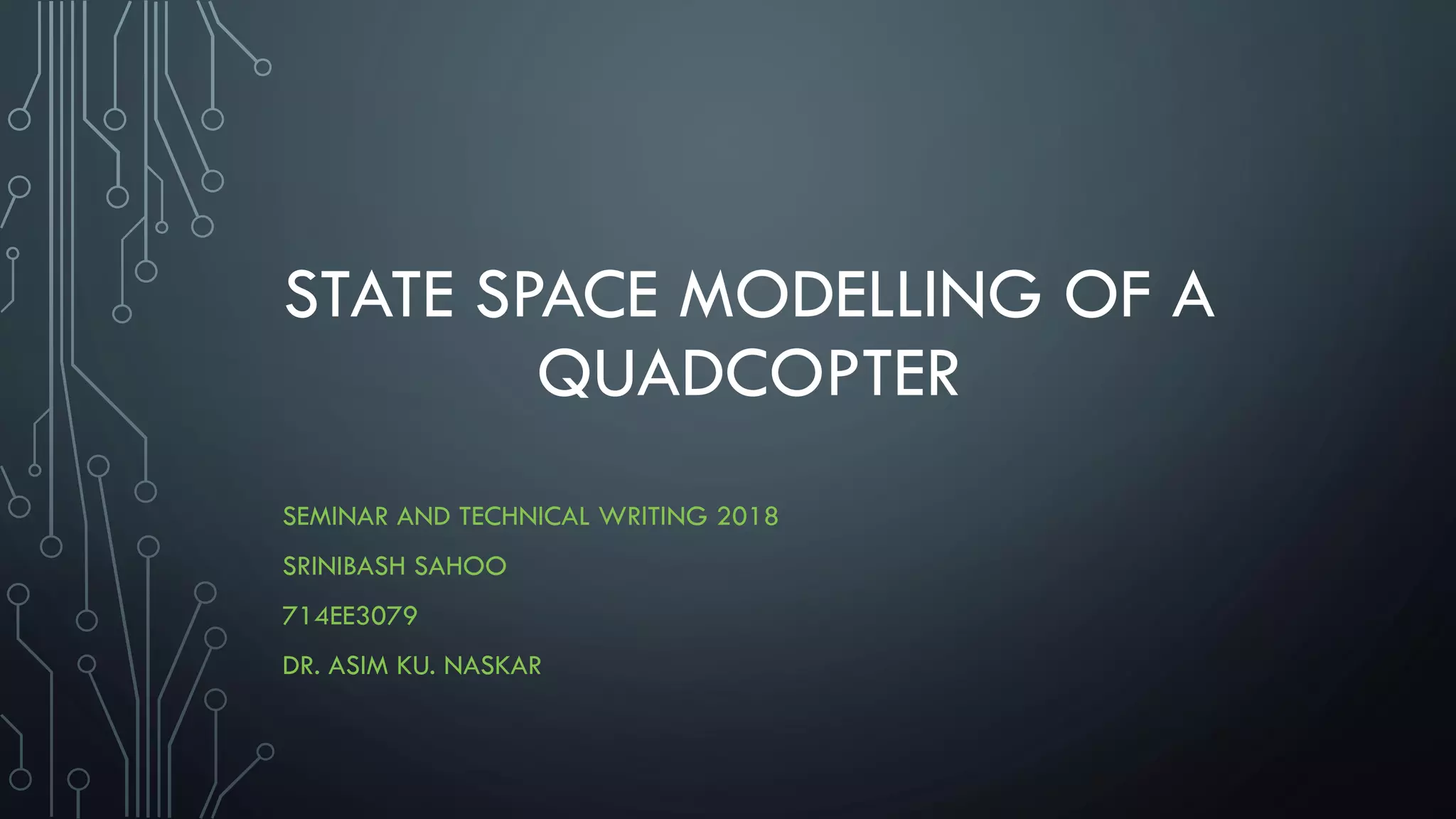
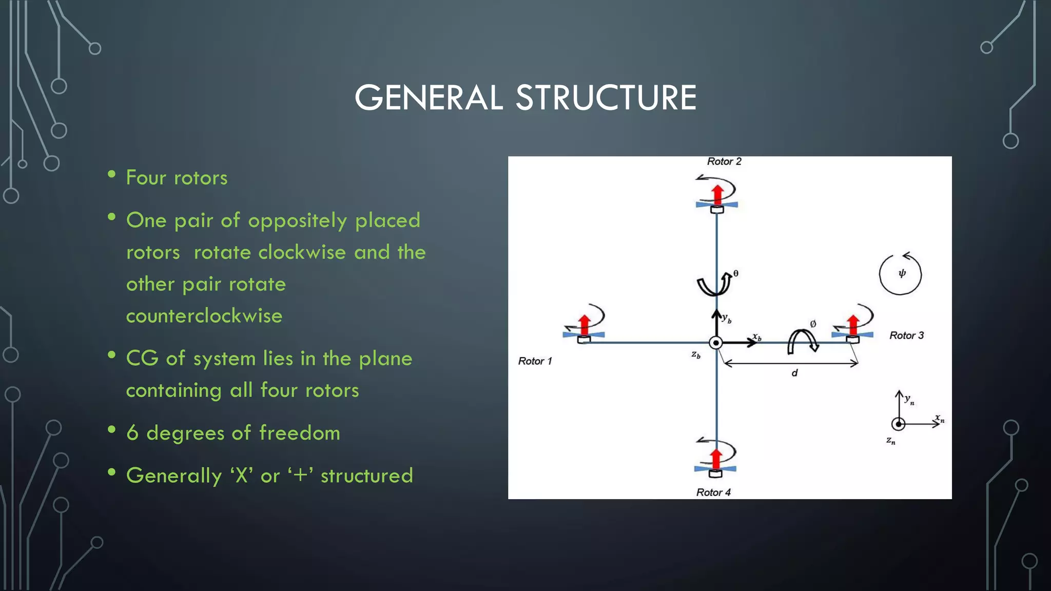
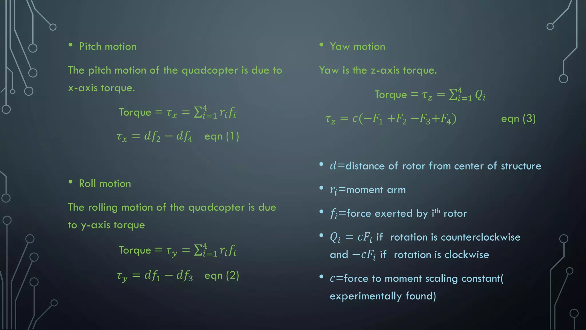
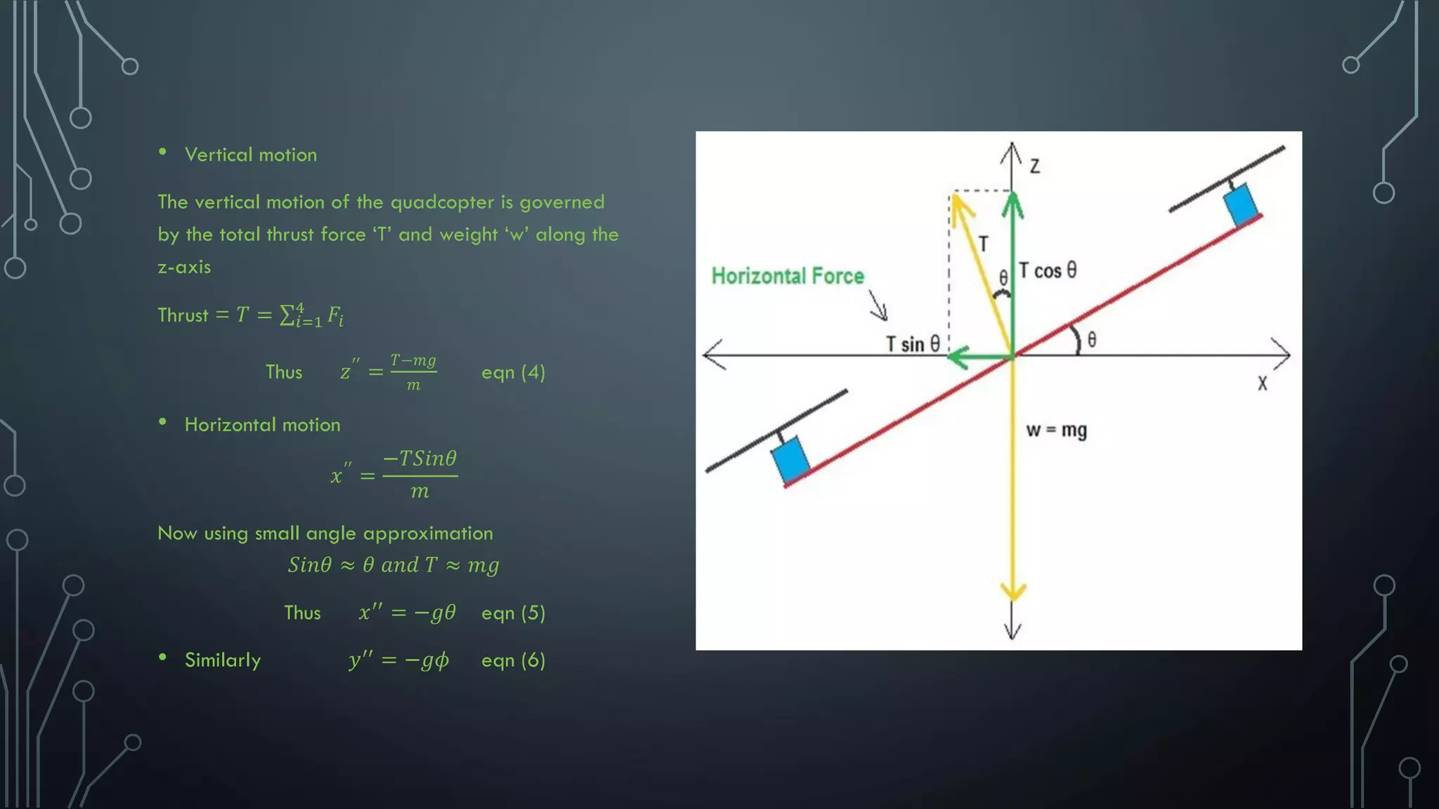
STATE SPACE MODELLING OF A
QUADCOPTER
SEMINAR AND TECHNICAL WRITING 2018
SRINIBASH SAHOO
714EE3079
DR. ASIM KU. NASKAR
GENERAL STRUCTURE
• Four rotors
• One pair of oppositely placed
rotors rotate clockwise and the
other pair rotate
counterclockwise
• CG of system lies in the plane
containing all four rotors
• 6 degrees of freedom
• Generally ‘X’ or ‘+’ structured
SYSTEM MODELLING
Dynamics
roll motion
Pitch motion
Yaw motion
Horizontal motion
Vertical motion
• Pitch motion
The pitch motion of the quadcopter is due to
x-axis torque.
Torque = 𝜏 𝑥 = σ𝑖=1
4
𝑟𝑖 𝑓𝑖
𝜏 𝑥 = 𝑑𝑓2 − 𝑑𝑓4 eqn (1)
• Roll motion
The rolling motion of the quadcopter is due
to y-axis torque
Torque = 𝜏 𝑦 = σ𝑖=1
4
𝑟𝑖 𝑓𝑖
𝜏 𝑦 = 𝑑𝑓1 − 𝑑𝑓3 eqn (2)
• Yaw motion
Yaw is the z-axis torque.
Torque = 𝜏 𝑧 = σ𝑖=1
4
𝑄𝑖
𝜏 𝑧 = 𝑐(−𝐹1 +𝐹2 −𝐹3+𝐹4) eqn (3)
• 𝑑=distance of rotor from center of structure
• 𝑟𝑖=moment arm
• 𝑓𝑖=force exerted by ith rotor
• 𝑄𝑖 = 𝑐𝐹𝑖 if rotation is counterclockwise
and −𝑐𝐹𝑖 if rotation is clockwise
• 𝑐=force to moment scaling constant(
experimentally found)
• Vertical motion
The vertical motion of the quadcopter is governed
by the total thrust force ‘T’ and weight ‘w’ along the
z-axis
Thrust = 𝑇 = σ𝑖=1
4
𝐹𝑖
Thus 𝑧′′
=
𝑇−𝑚𝑔
𝑚
eqn (4)
• Horizontal motion
𝑥′′
=
−𝑇𝑆𝑖𝑛𝜃
𝑚
Now using small angle approximation
𝑆𝑖𝑛𝜃 ≈ 𝜃 𝑎𝑛𝑑 𝑇 ≈ 𝑚𝑔
Thus 𝑥′′
= −𝑔𝜃 eqn (5)
• Similarly 𝑦′′
= −𝑔𝜙 eqn (6)
SELECTION OF STATES
• Position along x axis -𝑥
• Position along y axis -𝑦
• Position along z axis (height) - 𝑧
• Velocity along x axis – 𝑥′
• Velocity along y axis - 𝑦′
• Velocity along z axis - 𝑧′
• Pitch angle - 𝜙
• Roll angle - 𝜃
• Yaw angle - 𝜓
• Pitch rate - 𝜙′
• Roll rate - 𝜃′
• Yaw rate -𝜓′
STATE SPACE REPRESENTATION
• Thus the state space representation
of the quadcopter is obtained from
the equations
(1),(2),(3),(4),(5)and(6),expressed in
the standard form of
ሶ𝑥 = 𝐴𝑥 + 𝐵𝑢
𝑦 = 𝐶𝑥 + 𝐷𝑢
• Where 𝑢 = 𝑈1 𝑈2 𝑈3 𝑈4
𝑇
• 𝑈1is the total upward force on the
quadcopter along z-axis(𝑇 − 𝑚𝑔)
• 𝑈2 is the Pitch torque(𝜏 𝑥)
• 𝑈3 is the Roll torque(𝜏 𝑦)
• 𝑈4 is the Yaw torque(𝜏 𝑧)
𝑥′
𝑦′
𝑧′
𝑥′′
𝑦′′
𝑧′′
𝜙′
𝜃′
𝜓′
𝜙′′
𝜃′′
𝜓′′
=
0 0 0 1 0 0 0 0 0 0 0 0
0 0 0 0 1 0 0 0 0 0 0 0
0 0 0 0 0 1 0 0 0 0 0 0
0 0 0 0 0 0 0 −𝑔 0 0 0 0
0 0 0 0 0 0 −𝑔 0 0 0 0 0
0 0 0 0 0 0 0 0 0 0 0 0
0 0 0 0 0 0 0 0 0 1 0 0
0 0 0 0 0 0 0 0 0 0 1 0
0 0 0 0 0 0 0 0 0 0 0 1
0 0 0 0 0 0 0 0 0 0 0 0
0 0 0 0 0 0 0 0 0 0 0 0
0 0 0 0 0 0 0 0 0 0 0 0
×
𝑥
𝑦
𝑧
𝑥′
𝑦′
𝑧′
𝜙
𝜃
𝜓
𝜙′
𝜃′
𝜓′
+
0 0 0 0
0 0 0 0
0 0 0 0
0 0 0 0
0 0 0 0
ൗ1
𝑚 0 0 0
0 0 0 0
0 0 0 0
0 0 0 0
0 ൗ1
𝐼 𝑥
0 0
0 0 ൗ1
𝐼 𝑥
0
0 0 0 ൗ1
𝐼 𝑥
×
𝑈1
𝑈2
𝑈3
𝑈4
𝑥
𝑦
𝑧
𝜙
𝜃
𝜓
=
1 0 0 0 0 0 0 0 0 0 0 0
0 1 0 0 0 0 0 0 0 0 0 0
0 0 1 0 0 0 0 0 0 0 0 0
0 0 0 0 0 0 1 0 0 0 0 0
0 0 0 0 0 0 0 1 0 0 0 0
0 0 0 0 0 0 0 0 1 0 0 0
×
𝑥
𝑦
𝑧
𝑥′
𝑦′
𝑧′
𝜙
𝜃
𝜓
𝜙′
𝜃′
𝜓′
+
0 0 0 0
0 0 0 0
0 0 0 0
0 0 0 0
0 0 0 0
0 0 0 0
×
𝑈1
𝑈2
𝑈3
𝑈4
CONCLUSION
• Thus by the help of basic Newtonian equations the state space model of a
quad copter. The model designed here helps us to understand the dynamics of
the system and can also be used later for designing control laws for the
stability of the quadcopter(system).
REFERENCES
• Bora E, Erdinc A. Modeling and PD control of a Quadrotor VTOL vehicle. IEEE Intelligent Vehicles Symposium;
Istanbul, Turkey. 2007 Jun 13-15.
• Balas C. Modelling and linear control of a quadrotor [MSc Thesis]. Cranfield University; 2007.
• Mian AA, Daobo W. Modeling and back stepping-based nonlinear control strategy for a 6DOF quadrotor
helicopter.
• Totu MC, Koldbaek SK. Modelling and control of autonomous quad-rotor [Masters Thesis]. 2010.
• Bresciani T. Modelling, identification and control of a quadrotor helicopter [Masters Thesis]. 2008 Oct.
• de Oliveira MDC. Modeling, identification and control of a quadrotor aircraft [Masters Thesis]. 2011 Jun.
• Salih AL, Moghavvemi M, Mohamed HAF, Gaeid KS. Modelling and PID controller design for a quadrotor
unmanned air vehicle.

State space modelling of a quadcopter

  • 1.
    STATE SPACE MODELLINGOF A QUADCOPTER SEMINAR AND TECHNICAL WRITING 2018 SRINIBASH SAHOO 714EE3079 DR. ASIM KU. NASKAR
  • 2.
    GENERAL STRUCTURE • Fourrotors • One pair of oppositely placed rotors rotate clockwise and the other pair rotate counterclockwise • CG of system lies in the plane containing all four rotors • 6 degrees of freedom • Generally ‘X’ or ‘+’ structured
  • 3.
    SYSTEM MODELLING Dynamics roll motion Pitchmotion Yaw motion Horizontal motion Vertical motion
  • 4.
    • Pitch motion Thepitch motion of the quadcopter is due to x-axis torque. Torque = 𝜏 𝑥 = σ𝑖=1 4 𝑟𝑖 𝑓𝑖 𝜏 𝑥 = 𝑑𝑓2 − 𝑑𝑓4 eqn (1) • Roll motion The rolling motion of the quadcopter is due to y-axis torque Torque = 𝜏 𝑦 = σ𝑖=1 4 𝑟𝑖 𝑓𝑖 𝜏 𝑦 = 𝑑𝑓1 − 𝑑𝑓3 eqn (2) • Yaw motion Yaw is the z-axis torque. Torque = 𝜏 𝑧 = σ𝑖=1 4 𝑄𝑖 𝜏 𝑧 = 𝑐(−𝐹1 +𝐹2 −𝐹3+𝐹4) eqn (3) • 𝑑=distance of rotor from center of structure • 𝑟𝑖=moment arm • 𝑓𝑖=force exerted by ith rotor • 𝑄𝑖 = 𝑐𝐹𝑖 if rotation is counterclockwise and −𝑐𝐹𝑖 if rotation is clockwise • 𝑐=force to moment scaling constant( experimentally found)
  • 5.
    • Vertical motion Thevertical motion of the quadcopter is governed by the total thrust force ‘T’ and weight ‘w’ along the z-axis Thrust = 𝑇 = σ𝑖=1 4 𝐹𝑖 Thus 𝑧′′ = 𝑇−𝑚𝑔 𝑚 eqn (4) • Horizontal motion 𝑥′′ = −𝑇𝑆𝑖𝑛𝜃 𝑚 Now using small angle approximation 𝑆𝑖𝑛𝜃 ≈ 𝜃 𝑎𝑛𝑑 𝑇 ≈ 𝑚𝑔 Thus 𝑥′′ = −𝑔𝜃 eqn (5) • Similarly 𝑦′′ = −𝑔𝜙 eqn (6)
  • 6.
    SELECTION OF STATES •Position along x axis -𝑥 • Position along y axis -𝑦 • Position along z axis (height) - 𝑧 • Velocity along x axis – 𝑥′ • Velocity along y axis - 𝑦′ • Velocity along z axis - 𝑧′ • Pitch angle - 𝜙 • Roll angle - 𝜃 • Yaw angle - 𝜓 • Pitch rate - 𝜙′ • Roll rate - 𝜃′ • Yaw rate -𝜓′
  • 7.
    STATE SPACE REPRESENTATION •Thus the state space representation of the quadcopter is obtained from the equations (1),(2),(3),(4),(5)and(6),expressed in the standard form of ሶ𝑥 = 𝐴𝑥 + 𝐵𝑢 𝑦 = 𝐶𝑥 + 𝐷𝑢 • Where 𝑢 = 𝑈1 𝑈2 𝑈3 𝑈4 𝑇 • 𝑈1is the total upward force on the quadcopter along z-axis(𝑇 − 𝑚𝑔) • 𝑈2 is the Pitch torque(𝜏 𝑥) • 𝑈3 is the Roll torque(𝜏 𝑦) • 𝑈4 is the Yaw torque(𝜏 𝑧)
  • 8.
    𝑥′ 𝑦′ 𝑧′ 𝑥′′ 𝑦′′ 𝑧′′ 𝜙′ 𝜃′ 𝜓′ 𝜙′′ 𝜃′′ 𝜓′′ = 0 0 01 0 0 0 0 0 0 0 0 0 0 0 0 1 0 0 0 0 0 0 0 0 0 0 0 0 1 0 0 0 0 0 0 0 0 0 0 0 0 0 −𝑔 0 0 0 0 0 0 0 0 0 0 −𝑔 0 0 0 0 0 0 0 0 0 0 0 0 0 0 0 0 0 0 0 0 0 0 0 0 0 0 1 0 0 0 0 0 0 0 0 0 0 0 0 1 0 0 0 0 0 0 0 0 0 0 0 0 1 0 0 0 0 0 0 0 0 0 0 0 0 0 0 0 0 0 0 0 0 0 0 0 0 0 0 0 0 0 0 0 0 0 0 0 0 × 𝑥 𝑦 𝑧 𝑥′ 𝑦′ 𝑧′ 𝜙 𝜃 𝜓 𝜙′ 𝜃′ 𝜓′ + 0 0 0 0 0 0 0 0 0 0 0 0 0 0 0 0 0 0 0 0 ൗ1 𝑚 0 0 0 0 0 0 0 0 0 0 0 0 0 0 0 0 ൗ1 𝐼 𝑥 0 0 0 0 ൗ1 𝐼 𝑥 0 0 0 0 ൗ1 𝐼 𝑥 × 𝑈1 𝑈2 𝑈3 𝑈4 𝑥 𝑦 𝑧 𝜙 𝜃 𝜓 = 1 0 0 0 0 0 0 0 0 0 0 0 0 1 0 0 0 0 0 0 0 0 0 0 0 0 1 0 0 0 0 0 0 0 0 0 0 0 0 0 0 0 1 0 0 0 0 0 0 0 0 0 0 0 0 1 0 0 0 0 0 0 0 0 0 0 0 0 1 0 0 0 × 𝑥 𝑦 𝑧 𝑥′ 𝑦′ 𝑧′ 𝜙 𝜃 𝜓 𝜙′ 𝜃′ 𝜓′ + 0 0 0 0 0 0 0 0 0 0 0 0 0 0 0 0 0 0 0 0 0 0 0 0 × 𝑈1 𝑈2 𝑈3 𝑈4
  • 9.
    CONCLUSION • Thus bythe help of basic Newtonian equations the state space model of a quad copter. The model designed here helps us to understand the dynamics of the system and can also be used later for designing control laws for the stability of the quadcopter(system).
  • 10.
    REFERENCES • Bora E,Erdinc A. Modeling and PD control of a Quadrotor VTOL vehicle. IEEE Intelligent Vehicles Symposium; Istanbul, Turkey. 2007 Jun 13-15. • Balas C. Modelling and linear control of a quadrotor [MSc Thesis]. Cranfield University; 2007. • Mian AA, Daobo W. Modeling and back stepping-based nonlinear control strategy for a 6DOF quadrotor helicopter. • Totu MC, Koldbaek SK. Modelling and control of autonomous quad-rotor [Masters Thesis]. 2010. • Bresciani T. Modelling, identification and control of a quadrotor helicopter [Masters Thesis]. 2008 Oct. • de Oliveira MDC. Modeling, identification and control of a quadrotor aircraft [Masters Thesis]. 2011 Jun. • Salih AL, Moghavvemi M, Mohamed HAF, Gaeid KS. Modelling and PID controller design for a quadrotor unmanned air vehicle.