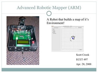
Advanced Robotic Mapper (ARM) Scott Crook ECET 497 Apr. 28, 2008 A Robot that builds a map of it’s Environment!
Block Diagram PC Operator  Interface Battery Charger Vehicle Wireless Link Power & Motor Drivers Mapping Sensors Main Controller & LCD Position & Orientation Tracking
Position & Orientation Tracking Block Optical Encoder Schematic/Hookup Diagram Optical Encoders IR Device which reads dark and light areas of a wheel on the motor shaft. Data is used to calculate displacement & orientation. Clever method of interface with the main controller…
Position & Orientation Tracking Block Down Counter Up Counter CLK EN EN CLK A !A B By using PSOC Timer blocks for up/down counters the need to use software interrupts is gone! The CPU can just check the count status of the timers to find the change since the last check. Quarter Resolution Decoder From Cypress App Note 2145
Position & Orientation Tracking Block Digital Compass Schematic/Hookup Diagrams Digital Compass I2C Bus Used to zero out accumulated error in orientation Compass is a Honeywell HMC 6352
Battery Charger MAX 713 Battery Charger Schematic How it Works: 2 modes (fast & trickle) Fast charge Regulate V Rsense  to 250mV via Q2 duty cycle Monitor battery voltage to determine when to switch to trickle charge Trickle charge Regulate charge current to fast charge current/8 to top off battery. I fast  = 250mV/Rsense
Main Controller/LCD PSOC User Modules model various HW (Timers, UART, LCD, etc) Control the Pinout of the final configuration for easier PCB layout. User modules have fairly well written interfaces so most of the low level code is done for you.
Software Overview - Main Controller Initialize HW Check for Commands Do Commanded Action Command Received? Check Position Y N
Software Overview OI Initialize Wait for port select Wait for connection request Connect to vehicle Wait for command event Translate & Relay user  command to vehicle Update Map Mapping/Position update? Disconnect Request Disconnect Y Y N N
Basic Tests Weight Requirements -> Scale Test W robot  = W scott + robot  - W scott Temperature Tolerance 40 F -> Run Robot outside in weather colder than 40 deg (weather permitting) for 10 minutes or place robot in refrigerator for 10 minutes then exercise all HW while in fridge. 80 F -> Turn up the heat to ~85 deg F and test LCD Testing LCD should show ARM run mode, Position, Orientation, and Bluetooth Connection Status Test Expected Actual Date LCD Report OK OK 3-23-08 Robot Weight < 10 lbs 3 lbs 2-5-08 Temp 40 deg F HW OK HW OK 2-16-08 Temp 80 deg F HW OK HW OK 2-16-08
Surface Detection Test ARM was placed in a known environment with one surface more that 4 feet away from the vehicle. One wall must be at least 4ft from ARM. Mapping output is shown on the left versus dimensioned sketch of the area on the right.
Bidirectional Square Path Test This test will determine how accurate the position and orientation tracking are. Robot travels a predetermined square path in both directions a set number of times. After each lap around the track the calculated position/orientation is compared to actual position/orientation and an error is computed
Bidirectional Square Path Test Results Dir Run  X exp (cm) X actual (cm) Error (cm) Y exp (cm) Y actual (cm) Error (cm)  exp (deg)  actual (deg) Error (deg) CW 1 -6.1 0 +6.1 6.9 12.5 +5.6 90 95 +5 CW 2 -19.6 -5 +14.6 -7 13.5 +20.5 100 104 +4 CW 3 -6.4 1.5 +7.9 -22.3 15 +37.3 100 118 +18 CW 4 8.4 0 -8.4 -34 16 +50 80 147 +67 CW 5 49.3 1 -48.3 -36.1 12 +48.1 95 172 +77 CCW 6 4 2.5 -1.5 20.9 12 -8.9 90 95 +5 CCW 7 4.7 -2 -6.7 31.1 6 -25.1 90 116 +26 CCW 8 16 0.5 -15.5 31.6 15 -16.6 90 107 +27 CCW 9 7.2 1.2 -6 32.7 5 -27.7 90 113 +23 CCW 10 -1.7 0 +1.7 47.5 8 -39.5 90 130 +40
Software Functionality Tests Test Method: Exercise all motion commands and data requests from OI Type Name Ok Date Command Motor Dir Y 2-5-08 Command Motor Speed Y 2-5-08 Command Turret Angle Y 2-5-08 Command CPU Reset Y 2-5-08 Request IR Data Y 2-5-08 Request Compass Data Y 2-5-08 Request ARM Info Y 2-5-08
Final Mapping Test Results
Budget Item Cost PCB Costs $66 Electromechanical $206.70 Sensors $197.38 Mechanical $254.31 Power (Batteries, etc) $75.70 Bluetooth $147.85 Prototyping Misc $141.61 LCDs $35.90 Motor Driver ICs $73.45 Other Parts (ICs, etc) $75.00 Shipping $176.99 Total $1450.89
Conclusions, Problems & Recommendations Overall Summary: Mapping accuracy is good at startup but begins to degrade over time due to errors in position/orientation tracking. The time it takes the vehicle to complete a scan makes mapping while moving extremely difficult. Problems: Accurate Position & Orientation tracking is extremely difficult  due to mechanical issues. The compass reading is very unstable when the motors are operating. Recommendations: Move the compass further away from the motors to reduce the magnetic interference from the motors. Characterizing the movement of the Servo would make the mapping even more accurate.
Demonstration Movie

Oral Report Rev2

  • 1.
    Advanced Robotic Mapper(ARM) Scott Crook ECET 497 Apr. 28, 2008 A Robot that builds a map of it’s Environment!
  • 2.
    Block Diagram PCOperator Interface Battery Charger Vehicle Wireless Link Power & Motor Drivers Mapping Sensors Main Controller & LCD Position & Orientation Tracking
  • 3.
    Position & OrientationTracking Block Optical Encoder Schematic/Hookup Diagram Optical Encoders IR Device which reads dark and light areas of a wheel on the motor shaft. Data is used to calculate displacement & orientation. Clever method of interface with the main controller…
  • 4.
    Position & OrientationTracking Block Down Counter Up Counter CLK EN EN CLK A !A B By using PSOC Timer blocks for up/down counters the need to use software interrupts is gone! The CPU can just check the count status of the timers to find the change since the last check. Quarter Resolution Decoder From Cypress App Note 2145
  • 5.
    Position & OrientationTracking Block Digital Compass Schematic/Hookup Diagrams Digital Compass I2C Bus Used to zero out accumulated error in orientation Compass is a Honeywell HMC 6352
  • 6.
    Battery Charger MAX713 Battery Charger Schematic How it Works: 2 modes (fast & trickle) Fast charge Regulate V Rsense to 250mV via Q2 duty cycle Monitor battery voltage to determine when to switch to trickle charge Trickle charge Regulate charge current to fast charge current/8 to top off battery. I fast = 250mV/Rsense
  • 7.
    Main Controller/LCD PSOCUser Modules model various HW (Timers, UART, LCD, etc) Control the Pinout of the final configuration for easier PCB layout. User modules have fairly well written interfaces so most of the low level code is done for you.
  • 8.
    Software Overview -Main Controller Initialize HW Check for Commands Do Commanded Action Command Received? Check Position Y N
  • 9.
    Software Overview OIInitialize Wait for port select Wait for connection request Connect to vehicle Wait for command event Translate & Relay user command to vehicle Update Map Mapping/Position update? Disconnect Request Disconnect Y Y N N
  • 10.
    Basic Tests WeightRequirements -> Scale Test W robot = W scott + robot - W scott Temperature Tolerance 40 F -> Run Robot outside in weather colder than 40 deg (weather permitting) for 10 minutes or place robot in refrigerator for 10 minutes then exercise all HW while in fridge. 80 F -> Turn up the heat to ~85 deg F and test LCD Testing LCD should show ARM run mode, Position, Orientation, and Bluetooth Connection Status Test Expected Actual Date LCD Report OK OK 3-23-08 Robot Weight < 10 lbs 3 lbs 2-5-08 Temp 40 deg F HW OK HW OK 2-16-08 Temp 80 deg F HW OK HW OK 2-16-08
  • 11.
    Surface Detection TestARM was placed in a known environment with one surface more that 4 feet away from the vehicle. One wall must be at least 4ft from ARM. Mapping output is shown on the left versus dimensioned sketch of the area on the right.
  • 12.
    Bidirectional Square PathTest This test will determine how accurate the position and orientation tracking are. Robot travels a predetermined square path in both directions a set number of times. After each lap around the track the calculated position/orientation is compared to actual position/orientation and an error is computed
  • 13.
    Bidirectional Square PathTest Results Dir Run X exp (cm) X actual (cm) Error (cm) Y exp (cm) Y actual (cm) Error (cm)  exp (deg)  actual (deg) Error (deg) CW 1 -6.1 0 +6.1 6.9 12.5 +5.6 90 95 +5 CW 2 -19.6 -5 +14.6 -7 13.5 +20.5 100 104 +4 CW 3 -6.4 1.5 +7.9 -22.3 15 +37.3 100 118 +18 CW 4 8.4 0 -8.4 -34 16 +50 80 147 +67 CW 5 49.3 1 -48.3 -36.1 12 +48.1 95 172 +77 CCW 6 4 2.5 -1.5 20.9 12 -8.9 90 95 +5 CCW 7 4.7 -2 -6.7 31.1 6 -25.1 90 116 +26 CCW 8 16 0.5 -15.5 31.6 15 -16.6 90 107 +27 CCW 9 7.2 1.2 -6 32.7 5 -27.7 90 113 +23 CCW 10 -1.7 0 +1.7 47.5 8 -39.5 90 130 +40
  • 14.
    Software Functionality TestsTest Method: Exercise all motion commands and data requests from OI Type Name Ok Date Command Motor Dir Y 2-5-08 Command Motor Speed Y 2-5-08 Command Turret Angle Y 2-5-08 Command CPU Reset Y 2-5-08 Request IR Data Y 2-5-08 Request Compass Data Y 2-5-08 Request ARM Info Y 2-5-08
  • 15.
  • 16.
    Budget Item CostPCB Costs $66 Electromechanical $206.70 Sensors $197.38 Mechanical $254.31 Power (Batteries, etc) $75.70 Bluetooth $147.85 Prototyping Misc $141.61 LCDs $35.90 Motor Driver ICs $73.45 Other Parts (ICs, etc) $75.00 Shipping $176.99 Total $1450.89
  • 17.
    Conclusions, Problems &Recommendations Overall Summary: Mapping accuracy is good at startup but begins to degrade over time due to errors in position/orientation tracking. The time it takes the vehicle to complete a scan makes mapping while moving extremely difficult. Problems: Accurate Position & Orientation tracking is extremely difficult due to mechanical issues. The compass reading is very unstable when the motors are operating. Recommendations: Move the compass further away from the motors to reduce the magnetic interference from the motors. Characterizing the movement of the Servo would make the mapping even more accurate.
  • 18.