ABB CLC Capacitor Fuses MV - Current Limiting Capacitor Fuse - ANSI Standard 1.2kV-4.3kV
•
0 likes•620 views

This document provides information on ABB's Type CLC capacitor fuses for indoor use on voltages from 1.2kV to 4.3/2.5kV. It describes the fuses' applications as current limiting and indicating devices for protecting individual low voltage capacitors. Guidelines are given for selecting the proper fuse based on the capacitor's voltage and current ratings to ensure adequate protection. Dimensional drawings and mounting configurations are depicted.

Recommended
More Related Content
What's hot
What's hot (20)
Similar to ABB CLC Capacitor Fuses MV - Current Limiting Capacitor Fuse - ANSI Standard 1.2kV-4.3kV
Similar to ABB CLC Capacitor Fuses MV - Current Limiting Capacitor Fuse - ANSI Standard 1.2kV-4.3kV (20)
More from Thorne & Derrick International
More from Thorne & Derrick International (20)
Recently uploaded
Recently uploaded (20)
ABB CLC Capacitor Fuses MV - Current Limiting Capacitor Fuse - ANSI Standard 1.2kV-4.3kV
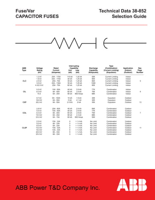
- 1. Fuse/Var Technical Data 38-852 CAPACITOR FUSES Selection Guide Interrupting Type ABB Voltage Rated Capability Discharge (Combination) Application See Type Rating Current Iind Icap Capability (Current Limiting) (Indoor) Page (kV) (Amperes) (kA) (kA) (Kilojoules) (Expulsion) (Outdoor) Number 1.2 kV 25A - 175A 115 kA 1.25 kA 50K Current Limiting Indoor 1.8 kV 25A - 175A 40 kA 1.25 kA 80K Current Limiting Indoor CLC 2.5 kV 25A - 75A 35 kA 1.25 kA 80K Current Limiting Indoor 5 3.0 kV 25A - 130A 35 kA 1.25 kA 100K Current Limiting Indoor 4.3/2.5 kV 25A - 75A 60 kA 1.25 kA 80K Current Limiting Indoor 5.5 kV 15A - 65A 40 kA 2.9 kA 77K Combination Indoor CIL 8.3 kV 8A - 40A 60 kA 2.9 kA 75K Combination Indoor 9 15.5 6A - 25A 90 kA 800 Amps 88K Combination Indoor 9.7 kV 6A - 100A 10 kA 1.9 kA 30K Expulsion Outdoor 16.6 kV 6A - 50A 5 kA 2.1 kA 30K Expulsion Outdoor CXP 26.2 kV 6A - 50A 2.5 KA .8 kA 30K Expulsion Outdoor 13 2.8 kV 25A - 80A 40 kA 2.9 kA 85K Combination Outdoor 5.5 kV 15A - 65A 40 kA 2.9 kA 77K Combination Outdoor COL 8.3 kV 8A - 40A 60 kA 2.9 kA 75K Combination Outdoor 7 15.5 kV 6A - 25A 90 kA 2.3 kA 88K Combination Outdoor 23.0 kV 6A - 15A 60 kA 800 Amps 50K Combination Outdoor 2.5 kV 15A - 33A 0 > 1.4 kA No Limit Combination Outdoor 5.0 kV 8A - 33A 0 > 1.4 kA No Limit Combination Outdoor 8.0 kV 6A - 33A 0 > 1.4 kA No Limit Combination Outdoor CLXP 10.0 kV 15A - 33A 0 > 1.4 kA No Limit Combination Outdoor 11 15.0 kV 10A - 33A 0 > 1.4 kA No Limit Combination Outdoor 20.0 kV 8A - 33A 0 > 1.4 kA No Limit Combination Outdoor 25.0 kV 8A - 33A 0 > 1.4 kA No Limit Combination Outdoor ABB Power T&D Company Inc.
- 2. Type CLC - Indoor, Current Limiting Capacitor Fuse 1.2 - 3.0 kV 5 GENERAL DESCRIPTION The Type CLC Fuse is a full range (partial range for 4.3/2.5kV ratings) current limiting capacitor fuse. It is designed for indoor use or in an enclosure, protected from outdoor weather condi- tions. The CLC fuses exist in 1200, 1800, 2500, 3000 volt and 4.3/2.5kV ratings. The primary application of these fuses is indi- vidual unit fusing of low voltage single and three phase capaci- tors in metal enclosed equipments. The 1200, 1800 and 3000 volt ratings are current limiting, indicating and non-disconnect- ing. The 2500 volt and 4.3/2.5kV ratings are current limiting, non- indicating and non-disconnecting. APPLICATION: CLC fuses are selected by taking the following steps: 1. Voltage: The voltage of the capacitor being protected should be less than or equal to the voltage of the fuse selected. The nearest available fuse should be used to assure that the voltage developed by the fuse during interruption does not damage the system. The 4.3/2.5kV fuse is a special rating for 2500V single-phase applications or 4300V 3-phase applications. To protect a 4800V single-phase capacitor , use two 4.3/2.5kV fuses in series. 2. Interrupting capacity: The interrupting capacity on CLC fuses is more than ade- quate to protect most applications. 3. Continuous current: The continuous current rating of the fuse should be 1.65 times the current flowing in each phase to protect against har- monics and switching currents. Ampere Interrupting Stype Rating Capacity Number Amperes 1200-Volt Type CLC Current Limiting, Indicating, Indoor (Enclosed) 25 115,000 4989C12A21 50 115,000 4989C12A22 75 115,000 4989C12A23 100 115,000 4989C12A24 120 115,000 4989C12A25 135 115,000 4989C12A26 150 115,000 4989C12A27 165 115,000 4989C12A28 175 115,000 4989C12A29 1800-Volt Type CLC Current Limiting, Indicating, Indoor (Enclosed) 25 40,000 4989C12A41 50 40,000 4989C12A42 75 40,000 4989C12A43 100 40,000 4989C12A44 120 40,000 4989C12A45 135 40,000 4989C12A46 150 40,000 4989C12A47 165 40,000 4989C12A48 175 40,000 4989C12A49 2500-Volt Type CLC Current Limiting, non-Indicating, Indoor (Enclosed) 25 35,000 4989C13A01 50 35,000 4989C13A02 75 35,000 4989C13A03 3000-Volt Type CLC Current Limiting, Indicating, Indoor (Enclosed) 25 35,000 4989C12A61 50 35,000 4989C12A62 75 35,000 4989C12A63 100 35,000 4989C12A64 115 35,000 4989C12A65 130 35,000 4989C12A66 4.3/2.5kV Type CLC Current Limiting, non-Indicating, Indoor (Enclosed) 25 60,000 4989C13A06 50 60,000 4989C13A07 75 60,000 4989C13A08 Note: Rated maximum voltage is 110% of nominal. Ref: IEEE C37.40 Type CLC Fuse Ratings Normal Applications On Typical 2400 And 4160 Volt Capacitor Available Fault Current: Rated KVA source XFMR/Impedance (source) Divide by the voltage to obtain available fault current EXAMPLE: 50 KVA/10% = 500,000 VA for 480 V, I = 1042 amperes TD 38-852CAPACITOR FUSES Selecting Type CLC Fuses Single-Phase: Ampere rating 1.65 x Three-Phase Units: Ampere rating 1.65 x kVAR kV kVAR √3 kV Three Phase Units 3 Phase kVAC 2400V 4160V 25 25A, 2.5 kV 25A, 4.3/2.5 kV 50 25A, 2.5 kV 25A, 4.3/2.5 kV 75 5CA, 2.5 kV 25A, 4.3/2.5 kV 100 50A, 2.5 kV 25A, 4.3/2.5 kV 125 50A, 2.5 kV 50A, 4.3/2.5 kV 150 75A, 2.5 kV 50A, 4.3/2.5 kV 175 75A, 2.5 kV 50A, 4.3/2.5 kV 200 75A, 2.5 kV 50A, 4.3/2.5 kV
- 3. Type CLC Fuses Blown Fuse Indicator Outline DIMENSIONS A B Volts 7.125 5.625 1200 9.125 7.625 1800 9.125 7.625 2500 12.375 10.875 3000 9.125 7.625 4.3/2.5 kV Typical CLC Fuse Mounting Arrangements Are Shown Below: Type CLC Fuse/Capacitor Edgemount Single Phase Capacitor Type CLC Fuse/Capacitor Edgemount on Single Phase Capacitor Type CLC Fuse/3-4.3/2.5 kV Fuses Mounted on 3 Phase Capacitor 6 TD 38-852CAPACITOR FUSES CLC Fuse Voltage Indicating? a* b** 1200 Yes 4.00 2.50 1800 Yes 5.00 2.50 2500 No 2.50 2.50 3000 Yes 6.00 2.50 4.3/2.5kV No 2.50 2.50 *These dimensions are the recommended clearances for 60kV BIL equipment. Increase these dimensions if higher BIL is required. **These dimensions are the minimum recommended clearances as determined by vari- ous 60 Hz. tests.These dimensions should be increased if feasible due to possible circuit variations and voltage transients. GROUNDED SURFACE OR ø INDICATIOR TRAV- Note: Torque to 15-20 Ft. lbs. FUSE RAIL LOCKWASHER WASHER CLC FUSE Note: Torque to 10-20 Ft. lbs. Note: Torque to 10-15 Ft. lbs. INSULATOR CLC FUSES LOCKNUT Note: Torque to 15-20 Ft. lbs. BOLT CLC FUSE Note: Torque to 10-15 Ft. lbs.