ABB CIL Capacitor Fuses MV - Current Limiting Capacitor Fuse For Use In Metal - Enclosed Equipment
•
0 likes•612 views

ABB CIL Capacitor Fuses MV - Current Limiting Capacitor Fuse For Use In Metal - Enclosed Equipment

Recommended
Recommended
More Related Content
What's hot
What's hot (20)
Similar to ABB CIL Capacitor Fuses MV - Current Limiting Capacitor Fuse For Use In Metal - Enclosed Equipment
Similar to ABB CIL Capacitor Fuses MV - Current Limiting Capacitor Fuse For Use In Metal - Enclosed Equipment (20)
More from Thorne & Derrick International
More from Thorne & Derrick International (20)
Recently uploaded
Recently uploaded (20)
ABB CIL Capacitor Fuses MV - Current Limiting Capacitor Fuse For Use In Metal - Enclosed Equipment
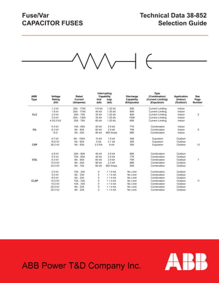
- 1. Fuse/Var Technical Data 38-852 CAPACITOR FUSES Selection Guide Interrupting Type ABB Voltage Rated Capability Discharge (Combination) Application See Type Rating Current Iind Icap Capability (Current Limiting) (Indoor) Page (kV) (Amperes) (kA) (kA) (Kilojoules) (Expulsion) (Outdoor) Number 1.2 kV 25A - 175A 115 kA 1.25 kA 50K Current Limiting Indoor 1.8 kV 25A - 175A 40 kA 1.25 kA 80K Current Limiting Indoor CLC 2.5 kV 25A - 75A 35 kA 1.25 kA 80K Current Limiting Indoor 5 3.0 kV 25A - 130A 35 kA 1.25 kA 100K Current Limiting Indoor 4.3/2.5 kV 25A - 75A 60 kA 1.25 kA 80K Current Limiting Indoor 5.5 kV 15A - 65A 40 kA 2.9 kA 77K Combination Indoor CIL 8.3 kV 8A - 40A 60 kA 2.9 kA 75K Combination Indoor 9 15.5 6A - 25A 90 kA 800 Amps 88K Combination Indoor 9.7 kV 6A - 100A 10 kA 1.9 kA 30K Expulsion Outdoor 16.6 kV 6A - 50A 5 kA 2.1 kA 30K Expulsion Outdoor CXP 26.2 kV 6A - 50A 2.5 KA .8 kA 30K Expulsion Outdoor 13 2.8 kV 25A - 80A 40 kA 2.9 kA 85K Combination Outdoor 5.5 kV 15A - 65A 40 kA 2.9 kA 77K Combination Outdoor COL 8.3 kV 8A - 40A 60 kA 2.9 kA 75K Combination Outdoor 7 15.5 kV 6A - 25A 90 kA 2.3 kA 88K Combination Outdoor 23.0 kV 6A - 15A 60 kA 800 Amps 50K Combination Outdoor 2.5 kV 15A - 33A 0 > 1.4 kA No Limit Combination Outdoor 5.0 kV 8A - 33A 0 > 1.4 kA No Limit Combination Outdoor 8.0 kV 6A - 33A 0 > 1.4 kA No Limit Combination Outdoor CLXP 10.0 kV 15A - 33A 0 > 1.4 kA No Limit Combination Outdoor 11 15.0 kV 10A - 33A 0 > 1.4 kA No Limit Combination Outdoor 20.0 kV 8A - 33A 0 > 1.4 kA No Limit Combination Outdoor 25.0 kV 8A - 33A 0 > 1.4 kA No Limit Combination Outdoor ABB Power T&D Company Inc.
- 2. Type CIL Fuses - (Indoor) Current Limiting Capacitor Fuse For Use In Metal - Enclosed Equipment 9 General Description The Type CIL Fuse is a full range current limiting capacitor fuse. It is designed for indoor use only. CIL fuses exist in voltage classes of 5.5 kV, 8.3 kV, 15.5 kV and 23kV. The primary application of these fuses is indi- vidual capacitor unit fusing for metal enclosed equipments. The CIL fuse is current limiting, indicating and disconnecting. The Type CIL current limiting capacitor fuse is a two part design: The high current section interrupts high 60 Hz fault currents and/or high frequency discharge current from parrallel capacitors. The low voltage section consists of a standard NEMA type K fuse link mounted in a fiber tube. The low current section interrupts fault current association with progressive failure of the capacitor unit DIELECTRIC, or 60Hz fault current limited by the circuit impedance to low values. This type of design reduces fuse replacement cost to the price of a NEMA type K fuse link when low current interruption occurs. The CIL capacitor fuse must be used with an ejector spring. (see page 10). This spring ejects the link’ s leader giving a position indication of a blown fuse. Application Voltage: The CIL fuse is used only for fusing individual single phase capacitor cans. Therefore, the CIL fuse voltage rating can be determined from the voltage rating of the capacitor unit - (see Table 1). Do not apply CIL fuses above their rated voltage. Energy: The CIL fuse is generally used on those capacitor banks where parallel energy is more than 20 kilo-joules or 6000 kVAR. The CIL fuse’s maximum parallel capacitor discharge energy rating is shown in the Technical Data table. CIL fuses are to be applied ONLY where there are 2 or more capacitors in parallel per group and where low inductively limited faults can flow . See appendix. Current Table 1 lists the individual fusing recommendations for applying CIL fuses in indoor capacitor banks. The fusing tables are based on the fol- lowing: Capacitor Current= kVar unit kV unit Minimum Fuse Current= Capacitor Current X 1.35 Protective Margin. The protective margin accounts for normal overvoltages, harmonics, capacitor tolerances and a 40° C. ambient. Note: Table 1 current ratings are based on 40° C. ambient style numbers shown in Table 2. Derated current ratings for 55° C. ambient applications, are also shown in Table 2. CAPACITOR FUSES TD 38-852 SELECT: Fuse Voltage Rating and Current Rating (40°C) TABLE 1 (The Fuse Current Ratings Shown are Based on Available Fuse Styles Shown in Table 2) Capacitor Voltage Fuse Voltage Rating Rating(kV) 50 kVar 100 kVar 150 kVar 200 kVar 300 kVar 2400 5.5 34 56 – – – 2770 5.5 27 56 – – – 4160 5.5 21 34 49 65 – 4800 5.5 21 34 49 56 – 6640 8.3 11 21 33 47 – 7200 8.3 11 21 33 39 – 7620 8.3 11 21 33 39 – 7960 8.3 11 17 26 39 – 8320 15.5 9 16 26 32 – 9960 15.5 9 14 21 32 – 12470 15.5 9 12 16 26 32 13280 15.5 – 12 16 21 32 13800 15.5 – 12 16 21 32 14400 15.5 – 9 14 21 32 19920 23.0 – – – 21 21 21600 23.0 – – – 21 21 Technical Data Maximum Design 2.8 5.5 8.3 15.5 23.0 Voltage (kV) Maximum Parallel 85 77 75 88 50 Capacitor Discharge Energy Rating (Kilo-Joules) 5 kHz Maximum 60 Hz 40 40 60 90 60 Inductive Current Interrupting (kA RMS Sym.) Maximum Peak 9 17 26 48 72 Recovery Voltage (kV) TABLE 2 (Select Fuse Style Number) STYLE NUMBER INCLUDES FUSE LINK Maximum Continuous NEMA Type CIL Fuse Design Current Type K With Voltage Rating Fuse Link Mounting (kV) (Amps) (Amp)* Hardware (40°C) (55° C) 5.5 6.05 21 18 15 279C420A08 5.5 6.05 27 23 20 279C420A09 5.5 6.05 34 29 25 279C420A10 5.5 6.05 40 34 30 279C420A11 5.5 6.05 49 42 40 279C420A12 5.5 6.05 56 48 50 279C420A13 5.5 6.05 65 55 65 279C420A14 8.3 9.13 11 9 8 279C420A16 8.3 9.13 14 12 10 279C420A17 8.3 9.13 17 14 12 279C420A18 8.3 9.13 21 18 15 279C420A19 8.3 9.13 26 22 20 279C420A20 8.3 9.13 33 28 25 279C420A21 8.3 9.13 39 33 30 279C420A22 8.3 9.13 47 40 40 279C420A23 15.5 17.05 9 8 6 279C420A26 15.5 17.05 12 10 8 279C420A27 15.5 17.05 14 12 10 279C420A28 15.5 17.05 16 14 12 279C420A29 15.5 17.05 21 18 15 279C420A30 15.5 17.05 26 22 20 279C420A31 15.5 17.05 32 27 25 279C420A32 23.0 25.3 21 18 15 279C420A40 *Fuse links are rated based on their melting characteristics. They can carry approximately 150% of their rating continuously. ** Ref: IEEE C37.40 **Rated Maximum Voltage
- 3. Type CIL - (Indoor) Current Limiting Capacitor Fuses Mounting & Ejector Spring 10 A B (Lbs.) A B Weight 5.5kV 14.00 7.75 3.5 8.3kV 14.00 7.75 3.5 15.5kV 16.25 10.00 4.2 23.0kV 18.375 12.125 4.5 TD 38-852 The CILfuse must be used with style number 898A431H02 ejector spring (fuse indicator). tioned such that the opening points to the capacitor unit. CAPACITOR FUSES Indoor Installation Type CIL Fuse /Capacitor Upright Indoor Installation Type CIL Fuse /Capacitor Edgemount