Federal Ministry
of Economics
and Technology
Sponsored by:
Mandated by Parliament
Federal Republic of Germany
5LB-05 Inductive Shielded Superconducting
Fault Current Limiter:
Test Results for Scaled Model
F. Moriconi1, A. Usoskin2, A. Henning3, S. Schmidt3, K. Bäuml4, T. Janetschek5
1Bruker EST, Fremont, CA, USA, 2Bruker HTS GmbH, Alzenau, 3Bruker Advanced Supercon GmbH, Cologne,
Germany, 4Schneider Electric Sachsenwerk GmbH, Regensburg, Germany, 5Stadtwerke Augsburg Energie
GmbH, Augsburg, Germany.
Bruker EST
Industrial Plant
Outline
• Product Development
• Application 10.6 kV
• Principle of Operation iSFCL
• Prototype test results
• Model Validation
• Future Work
• Q&A
ASC 2012 – Portland-Oct 12 - oral # 5LB-05 2
Bruker EST
Planned iSFCL in Augsburg
Substation
iSFCL
Industrial Plant
Federal Ministry
of Economics
and Technology
Sponsored by:
Mandated by Parliament
Federal Republic of Germany
iSFCL Funded Project
• Project
Inductive shielded superconducting fault current limiter
(iSFCL) as a "smart grid" device for energy efficiency
and security of electricity supply
• Application
Fault current management in Augsburg network
connecting substation to an industrial plant MTU Onsite
Energy (manufacturing and testing of CHP plants)
• Partners
3ASC 2012 – Portland-Oct 12 - oral # 5LB-05
Bruker EST
MTU On-Site Power – 10.6 kV
iSFCL Technical Requirements
Augsburg Installation
Line Voltage = 10.6 kV
Rated Current = 817 A
Prospective Peak = 25.1 kA
Prospective Symmetric = 10.1 kA
Limited Peak < 5 kA
Limited Symmetric < 2 kA
Fault Duration 500 ms
10.6 kV
80% Fault
Reduction
Additional requirements
• Active losses smaller than for
comparable Current Limiting
Reactor CLR (including cryo-
losses)
• Low maintenance
• Fail Safe
4ASC 2012 – Portland-Oct 12 - oral # 5LB-05
Bruker EST
iSFCL Technical Requirements
Augsburg Installation
MTU On-Site Power – 10.6 kV
Line Voltage = 10.6 kV
Rated Current = 817 A
10.6 kV
5
Property iSFCL 15-MVA reactor
Total impedance
(normal operation)
1.4 Ω ⇒
Voltage change Uϕ
~5%
2.7 Ω ⇒
Voltage change Uϕ
~10%
Operating losses 45 – 50 kW
(incl. cryogenics)
95 kW
Impedance increase at
fault
Factor 2 none
Fault current limitation
first peak
Factor 5 Factor 5
ASC 2012 – Portland-Oct 12 - oral # 5LB-05
Bruker EST
iSFCL Advantages
• Low operating losses compared to conventional reactors, low
resistive losses/cryo-losses, and low insertion impedance
• Low voltage drop under normal operating conditions
• Fail-safe triggering through material properties / no active
trigger / no control needed
• Fast response time (first peak is limited)
• Self-recovery
• Long fault duration (up to 500 ms and possibly longer)
• Easy configurability of key operating parameters (switching
current)
• Scalable due to flexible design (in size, power and voltage)
• Smaller than competing technologies for similar performances
6ASC 2012 – Portland-Oct 12 - oral # 5LB-05
Bruker EST
Normal Operating Conditions
• HTS is superconducting
⇒ no magnetic field penetrates the HTS shield
⇒ reduced flux linkage of primary winding
⇒ primary inductance mainly due to stray fields
⇒ small insertion impedance
⇒ primary winding smaller than a comparable air coil
reactor
Fault Conditions
• HTS becomes normal conducting
⇒ magnetic flux penetrates shield and iron core
⇒ increased flux linkage of primary winding
⇒ large impedance gain
CB
Primary coil
Load
Cryostat
Superconducting short-circuited
secondary
CB
Primary coil
Load
Cryostat
Superconducting short-circuited
secondary
iSFCL Principle of Operation
7ASC 2012 – Portland-Oct 12 - oral # 5LB-05
Bruker EST
0%
10%
20%
30%
40%
50%
60%
70%
80%
0 500 1000 1500 2000
VOLTAGEDROPACROSSFCL
[%ofSourceV]
LIMITED CURRENT – PRIMARY [A]
Air Core
Iron Core
Shielded
Unshielded
GAIN (2-3)
iSFCL
iSFCL Principle of Operation
8
Shielded
Iron-core
Air-Core
Iron-Core
Unshielded
Iron-Core
Quenched Shield
ASC 2012 – Portland-Oct 12 - oral # 5LB-05
Bruker EST
2500mm
iSFCL DESIGN
9
Shield
ASC 2012 – Portland-Oct 12 - oral # 5LB-05
Bruker EST
Open-Core Prototype
10
Core Area 358 cm2 Core Height 710 mm
Core Weight 230 Kg ID Primary 454 mm
OD Primary 625 mm H Primary 140 mm
# of Turns 20 Inductance 240 µH (air core)
# of Modules 3 Inductance 470 µH (iron core)
HTS Current 6 kA HTS Material 12 m
ASC 2012 – Portland-Oct 12 - oral # 5LB-05
Bruker EST
Test Circuit
11
V Source = 300 V Amplitude
Z Source = 0.154 Ohms (mainly resistive)
Z Load = 0.937 Ohms (power factor 0.98)
• Load Current Only
• Short-Circuit
• Long Duration Short-Circuit
ASC 2012 – Portland-Oct 12 - oral # 5LB-05
Bruker EST
Circuit Calibration
12
-2000
-1500
-1000
-500
0
500
1000
1500
2000
-500
-400
-300
-200
-100
0
100
200
300
400
500 0.00
0.01
0.02
0.03
0.04
0.05
0.06
0.07
0.08
0.09
0.10
0.11
0.12
0.13
0.14
0.15
0.16
0.17
0.18
0.19
0.20
0.21
0.22
CURRENT[A]
VOLTAGE[V]
Time [s]
Source Voltage Prospective Current
I prospective= 1950 A
I Load= 285 A
ASC 2012 – Portland-Oct 12 - oral # 5LB-05
Bruker EST
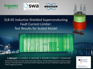
Open-Core iSFCL Measurements
13
-2000
-1500
-1000
-500
0
500
1000
1500
2000
-200
-150
-100
-50
0
50
100
150
200
0.00
0.01
0.02
0.03
0.04
0.05
0.06
0.07
0.08
0.09
0.10
0.11
0.12
0.13
0.14
0.15
0.16
0.17
0.18
0.19
0.20
0.21
0.22
CURRENT[A]
VOLTAGE[V]
Time [s]
Voltage iSFCL Prospective Current Limited Current
Z pre-fault= 55 mΩ
16V, 285A
Inductance 175 µΗ
Z fault= 143 mΩ
187V, 1285A
Inductance 455 µΗ
Impedance GAIN= 2.6
ASC 2012 – Portland-Oct 12 - oral # 5LB-05
Bruker EST
iSFCL Measurements
Quench Stability and Robustness
14
-1500
-1000
-500
0
500
1000
1500
0 0,02 0,04 0,06 0,08 0,1 0,12 0,14 0,16 0,18 0,2 0,22
CurrentinA
Time in s
ComparisonOpen Core 20120117-12 and 20120127-19
I 20120117-12 I 20120127-19
Î = 325A
(20120117-12)
Î = 325A
(20120117-12)
Î = 275A
(20120127-19)
-200
-150
-100
-50
0
50
100
150
200
0 0,02 0,04 0,06 0,08 0,1 0,12 0,14 0,16 0,18 0,2 0,22
VoltageinV
Time in s
ComparisonOpen Core 20120117-12 and 20120127-19
U 20120117-12 U 20120127-19NO DEGRADATION of PERFORMANCE
AFTER SEVERAL QUENCHES (~100)
ASC 2012 – Portland-Oct 12 - oral # 5LB-05
Bruker EST
iSFCL Measurements
Long Duration Short-Circuit
15
~0.5 s faults were achieved
Shunt resistance must be revised
-600
-400
-200
0
200
400
600
-150
-100
-50
0
50
100
150
0 0,1 0,2 0,3 0,4 0,5
CurrentinA
VoltageinV
Time in s
Voltage at iSFCL Current
ASC 2012 – Portland-Oct 12 - oral # 5LB-05
Bruker EST
Quench Model Validation
16
-0.2
0.0
0.2
0.4
0.6
0.8
1.0
1.2
1.4
1.6
1.8
2.0
2.2
0.0 0.1 0.2 0.3 0.4 0.5 0.6 0.7 0.8 0.9 1.0 1.1
E/Ec
J/Jc
Measured (J/Jc)^43 Power Function
ASC 2012 – Portland-Oct 12 - oral # 5LB-05
Bruker EST
Finite Elements Model Validation
17
-2000
-1500
-1000
-500
0
500
1000
1500
2000
0.00
0.01
0.02
0.03
0.04
0.05
0.06
0.07
0.08
0.09
0.10
0.11
0.12
0.13
0.14
0.15
0.16
0.17
0.18
0.19
0.20
0.21
0.22
CURRENT[A]
Time [s]
Prospective Current Limited Current Limited Current Predicted
0.75 T
Measured Measured
3 mT
ASC 2012 – Portland-Oct 12 - oral # 5LB-05
Bruker EST
Finite Elements Model Validation
18
0.75 T
Measured
3 mT
-200
-150
-100
-50
0
50
100
150
200
0.00
0.01
0.02
0.03
0.04
0.05
0.06
0.07
0.08
0.09
0.10
0.11
0.12
0.13
0.14
0.15
0.16
0.17
0.18
0.19
0.20
0.21
0.22
VOLTAGE[V]
Time [s]
Voltage iSFCL Voltage iSFCL Predicted
ASC 2012 – Portland-Oct 12 - oral # 5LB-05
Bruker EST
From Prototype to Full-Scale
19
2500mm
Prototype Full-Scale
358 Core Area cm2 1250
710 Core Height mm 2500
230 Core Weight Kg 2750
454 ID Primary mm 977
625 OD Primary mm 1180
140 H Primary mm 600
20 # of Turns # 74
0.24 Inductance air-core mH 5
0.47 Inductance iron-core mH 16
3 # of Modules # 10
6 HTS Current kA 50
12 HTS Material m 250
ASC 2012 – Portland-Oct 12 - oral # 5LB-05
Bruker EST
25 I [kA]
15
10
20
5
0
Predicted Performance iSFCL Augsburg
10.6kV, 817A, 80% Fault Reduction
20
25kA PEAK
5kA PEAK
ASC 2012 – Portland-Oct 12 - oral # 5LB-05
Bruker EST
Future Work
• Perform AC Losses Measurements (CAPS)
• Assemble and test Full-Scale HTS Modules
• Integrate single-phase 12 kV- 820A device
• High-Power and HV testing of single-phase
• Build, Test and Commission 12kV, 3-Phase
Augsburg Installation
21ASC 2012 – Portland-Oct 12 - oral # 5LB-05
www.bruker-est.com
ASC 2012 – Portland-Oct 12 - oral # 5LB-05

Inductive shielded superconducting fault current limiter: test results for scaled model

  • 1.
    Federal Ministry of Economics andTechnology Sponsored by: Mandated by Parliament Federal Republic of Germany 5LB-05 Inductive Shielded Superconducting Fault Current Limiter: Test Results for Scaled Model F. Moriconi1, A. Usoskin2, A. Henning3, S. Schmidt3, K. Bäuml4, T. Janetschek5 1Bruker EST, Fremont, CA, USA, 2Bruker HTS GmbH, Alzenau, 3Bruker Advanced Supercon GmbH, Cologne, Germany, 4Schneider Electric Sachsenwerk GmbH, Regensburg, Germany, 5Stadtwerke Augsburg Energie GmbH, Augsburg, Germany.
  • 2.
    Bruker EST Industrial Plant Outline •Product Development • Application 10.6 kV • Principle of Operation iSFCL • Prototype test results • Model Validation • Future Work • Q&A ASC 2012 – Portland-Oct 12 - oral # 5LB-05 2
  • 3.
    Bruker EST Planned iSFCLin Augsburg Substation iSFCL Industrial Plant Federal Ministry of Economics and Technology Sponsored by: Mandated by Parliament Federal Republic of Germany iSFCL Funded Project • Project Inductive shielded superconducting fault current limiter (iSFCL) as a "smart grid" device for energy efficiency and security of electricity supply • Application Fault current management in Augsburg network connecting substation to an industrial plant MTU Onsite Energy (manufacturing and testing of CHP plants) • Partners 3ASC 2012 – Portland-Oct 12 - oral # 5LB-05
  • 4.
    Bruker EST MTU On-SitePower – 10.6 kV iSFCL Technical Requirements Augsburg Installation Line Voltage = 10.6 kV Rated Current = 817 A Prospective Peak = 25.1 kA Prospective Symmetric = 10.1 kA Limited Peak < 5 kA Limited Symmetric < 2 kA Fault Duration 500 ms 10.6 kV 80% Fault Reduction Additional requirements • Active losses smaller than for comparable Current Limiting Reactor CLR (including cryo- losses) • Low maintenance • Fail Safe 4ASC 2012 – Portland-Oct 12 - oral # 5LB-05
  • 5.
    Bruker EST iSFCL TechnicalRequirements Augsburg Installation MTU On-Site Power – 10.6 kV Line Voltage = 10.6 kV Rated Current = 817 A 10.6 kV 5 Property iSFCL 15-MVA reactor Total impedance (normal operation) 1.4 Ω ⇒ Voltage change Uϕ ~5% 2.7 Ω ⇒ Voltage change Uϕ ~10% Operating losses 45 – 50 kW (incl. cryogenics) 95 kW Impedance increase at fault Factor 2 none Fault current limitation first peak Factor 5 Factor 5 ASC 2012 – Portland-Oct 12 - oral # 5LB-05
  • 6.
    Bruker EST iSFCL Advantages •Low operating losses compared to conventional reactors, low resistive losses/cryo-losses, and low insertion impedance • Low voltage drop under normal operating conditions • Fail-safe triggering through material properties / no active trigger / no control needed • Fast response time (first peak is limited) • Self-recovery • Long fault duration (up to 500 ms and possibly longer) • Easy configurability of key operating parameters (switching current) • Scalable due to flexible design (in size, power and voltage) • Smaller than competing technologies for similar performances 6ASC 2012 – Portland-Oct 12 - oral # 5LB-05
  • 7.
    Bruker EST Normal OperatingConditions • HTS is superconducting ⇒ no magnetic field penetrates the HTS shield ⇒ reduced flux linkage of primary winding ⇒ primary inductance mainly due to stray fields ⇒ small insertion impedance ⇒ primary winding smaller than a comparable air coil reactor Fault Conditions • HTS becomes normal conducting ⇒ magnetic flux penetrates shield and iron core ⇒ increased flux linkage of primary winding ⇒ large impedance gain CB Primary coil Load Cryostat Superconducting short-circuited secondary CB Primary coil Load Cryostat Superconducting short-circuited secondary iSFCL Principle of Operation 7ASC 2012 – Portland-Oct 12 - oral # 5LB-05
  • 8.
    Bruker EST 0% 10% 20% 30% 40% 50% 60% 70% 80% 0 5001000 1500 2000 VOLTAGEDROPACROSSFCL [%ofSourceV] LIMITED CURRENT – PRIMARY [A] Air Core Iron Core Shielded Unshielded GAIN (2-3) iSFCL iSFCL Principle of Operation 8 Shielded Iron-core Air-Core Iron-Core Unshielded Iron-Core Quenched Shield ASC 2012 – Portland-Oct 12 - oral # 5LB-05
  • 9.
    Bruker EST 2500mm iSFCL DESIGN 9 Shield ASC2012 – Portland-Oct 12 - oral # 5LB-05
  • 10.
    Bruker EST Open-Core Prototype 10 CoreArea 358 cm2 Core Height 710 mm Core Weight 230 Kg ID Primary 454 mm OD Primary 625 mm H Primary 140 mm # of Turns 20 Inductance 240 µH (air core) # of Modules 3 Inductance 470 µH (iron core) HTS Current 6 kA HTS Material 12 m ASC 2012 – Portland-Oct 12 - oral # 5LB-05
  • 11.
    Bruker EST Test Circuit 11 VSource = 300 V Amplitude Z Source = 0.154 Ohms (mainly resistive) Z Load = 0.937 Ohms (power factor 0.98) • Load Current Only • Short-Circuit • Long Duration Short-Circuit ASC 2012 – Portland-Oct 12 - oral # 5LB-05
  • 12.
    Bruker EST Circuit Calibration 12 -2000 -1500 -1000 -500 0 500 1000 1500 2000 -500 -400 -300 -200 -100 0 100 200 300 400 5000.00 0.01 0.02 0.03 0.04 0.05 0.06 0.07 0.08 0.09 0.10 0.11 0.12 0.13 0.14 0.15 0.16 0.17 0.18 0.19 0.20 0.21 0.22 CURRENT[A] VOLTAGE[V] Time [s] Source Voltage Prospective Current I prospective= 1950 A I Load= 285 A ASC 2012 – Portland-Oct 12 - oral # 5LB-05
  • 13.
    Bruker EST Open-Core iSFCLMeasurements 13 -2000 -1500 -1000 -500 0 500 1000 1500 2000 -200 -150 -100 -50 0 50 100 150 200 0.00 0.01 0.02 0.03 0.04 0.05 0.06 0.07 0.08 0.09 0.10 0.11 0.12 0.13 0.14 0.15 0.16 0.17 0.18 0.19 0.20 0.21 0.22 CURRENT[A] VOLTAGE[V] Time [s] Voltage iSFCL Prospective Current Limited Current Z pre-fault= 55 mΩ 16V, 285A Inductance 175 µΗ Z fault= 143 mΩ 187V, 1285A Inductance 455 µΗ Impedance GAIN= 2.6 ASC 2012 – Portland-Oct 12 - oral # 5LB-05
  • 14.
    Bruker EST iSFCL Measurements QuenchStability and Robustness 14 -1500 -1000 -500 0 500 1000 1500 0 0,02 0,04 0,06 0,08 0,1 0,12 0,14 0,16 0,18 0,2 0,22 CurrentinA Time in s ComparisonOpen Core 20120117-12 and 20120127-19 I 20120117-12 I 20120127-19 Î = 325A (20120117-12) Î = 325A (20120117-12) Î = 275A (20120127-19) -200 -150 -100 -50 0 50 100 150 200 0 0,02 0,04 0,06 0,08 0,1 0,12 0,14 0,16 0,18 0,2 0,22 VoltageinV Time in s ComparisonOpen Core 20120117-12 and 20120127-19 U 20120117-12 U 20120127-19NO DEGRADATION of PERFORMANCE AFTER SEVERAL QUENCHES (~100) ASC 2012 – Portland-Oct 12 - oral # 5LB-05
  • 15.
    Bruker EST iSFCL Measurements LongDuration Short-Circuit 15 ~0.5 s faults were achieved Shunt resistance must be revised -600 -400 -200 0 200 400 600 -150 -100 -50 0 50 100 150 0 0,1 0,2 0,3 0,4 0,5 CurrentinA VoltageinV Time in s Voltage at iSFCL Current ASC 2012 – Portland-Oct 12 - oral # 5LB-05
  • 16.
    Bruker EST Quench ModelValidation 16 -0.2 0.0 0.2 0.4 0.6 0.8 1.0 1.2 1.4 1.6 1.8 2.0 2.2 0.0 0.1 0.2 0.3 0.4 0.5 0.6 0.7 0.8 0.9 1.0 1.1 E/Ec J/Jc Measured (J/Jc)^43 Power Function ASC 2012 – Portland-Oct 12 - oral # 5LB-05
  • 17.
    Bruker EST Finite ElementsModel Validation 17 -2000 -1500 -1000 -500 0 500 1000 1500 2000 0.00 0.01 0.02 0.03 0.04 0.05 0.06 0.07 0.08 0.09 0.10 0.11 0.12 0.13 0.14 0.15 0.16 0.17 0.18 0.19 0.20 0.21 0.22 CURRENT[A] Time [s] Prospective Current Limited Current Limited Current Predicted 0.75 T Measured Measured 3 mT ASC 2012 – Portland-Oct 12 - oral # 5LB-05
  • 18.
    Bruker EST Finite ElementsModel Validation 18 0.75 T Measured 3 mT -200 -150 -100 -50 0 50 100 150 200 0.00 0.01 0.02 0.03 0.04 0.05 0.06 0.07 0.08 0.09 0.10 0.11 0.12 0.13 0.14 0.15 0.16 0.17 0.18 0.19 0.20 0.21 0.22 VOLTAGE[V] Time [s] Voltage iSFCL Voltage iSFCL Predicted ASC 2012 – Portland-Oct 12 - oral # 5LB-05
  • 19.
    Bruker EST From Prototypeto Full-Scale 19 2500mm Prototype Full-Scale 358 Core Area cm2 1250 710 Core Height mm 2500 230 Core Weight Kg 2750 454 ID Primary mm 977 625 OD Primary mm 1180 140 H Primary mm 600 20 # of Turns # 74 0.24 Inductance air-core mH 5 0.47 Inductance iron-core mH 16 3 # of Modules # 10 6 HTS Current kA 50 12 HTS Material m 250 ASC 2012 – Portland-Oct 12 - oral # 5LB-05
  • 20.
    Bruker EST 25 I[kA] 15 10 20 5 0 Predicted Performance iSFCL Augsburg 10.6kV, 817A, 80% Fault Reduction 20 25kA PEAK 5kA PEAK ASC 2012 – Portland-Oct 12 - oral # 5LB-05
  • 21.
    Bruker EST Future Work •Perform AC Losses Measurements (CAPS) • Assemble and test Full-Scale HTS Modules • Integrate single-phase 12 kV- 820A device • High-Power and HV testing of single-phase • Build, Test and Commission 12kV, 3-Phase Augsburg Installation 21ASC 2012 – Portland-Oct 12 - oral # 5LB-05
  • 22.
    www.bruker-est.com ASC 2012 –Portland-Oct 12 - oral # 5LB-05