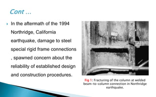
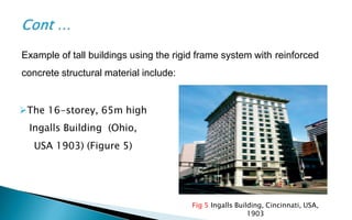
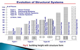
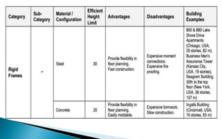
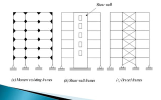
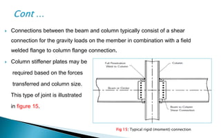
‫ـــــــــــــــــــــــــــــــــــــــــــــــــــــــــــــــــــــــــــــــــــــــــــــــــــــــــــــــــــــــــــــ‬‫ـــ‬‫ـــــــــــــــــــــــــــــــــــــــــــــــــــــــــــــــــــــــــــــــــــــــــــــــــــــــــــــــــــــــــــــ‬
Cyprus International University
Civil Engineering Department
CVL548 HIGH RISE BUILDING
Title : Rigid Frame systems
Submitted to : Dr. Alireza Rezaei
By Group 1 : Ali Ezreg ID :20153333
ID :20153680Muftah Aljoat
ID :20153312Adel Milad
May/2016
 History
 Introduction
 What is a Rigid Frame system?
 Applications of Rigid Frame system
 Material Properties
 How is Connect the Rigid Frame system?
 Considerations of Rigid Frame Design
 Behavior of rigid frames under Lateral loads
 Methods of Rigid Frame Design
 Advantages disadvantages
 Environment and Health Safety
 Case Study
 Conclusion
 A tall building boom in the late 1920s and early 1930s in urban centers
Chicago and New York .
 In the 1960s and 1970s, Professor Egor Popov at the University of
California at Berkeley and other researchers began to perform cyclic
laboratory testing of steel moment framing.
 As a result of the apparent high performance of these structures, the
building codes from the 1960s adopted preferential design criteria for
steel moment frames.
Fig 1: Fracturing of the column at welded
beam-to-column connection in Northridge
earthquake.
 In the aftermath of the 1994
Northridge, California
earthquake, damage to steel
special rigid frame connections
, spawned concern about the
reliability of established design
and construction procedures.
 Rigid frame systems, also called moment frame systems, are used in
steel and reinforced concrete buildings. This system consists of beams
and columns .
 Reinforced concrete and steel in rigid frames are used In earlier high-rise
buildings, while concrete were under development, steel frames were
predominated.
 A rigid frame is an unbraced frame, that is capable of resisting both
vertical and lateral loads by the bending of beams and columns.
 Stiffness of the rigid frame is provided mainly by the bending rigidity of
beams and columns that have rigid connections.
 A rigid frame system are comment system using in high rise
building in this years on the world that has more stability and
less damage due to Natural disasters like earthquake and wind
load.
 A rigid-frame structure is a structure made up of linear
elements, typically beams and columns, that are connected to
one another at their ends with joints that do not allow any
relative rotation to happen between the ends of the members.
Fig 2 Rigid frame structure under construction
Some examples of tall buildings using the rigid frame system with steel
structural material include:
Fig 4 The 12-storey, 55m high Home
Insurance Building (Chicago,1885)
Fig 3 The 21-storey, 94m high Lever House
(New York, 1952)
Fig 5 Ingalls Building, Cincinnati, USA,
1903
The 16-storey, 65m high
Ingalls Building (Ohio,
USA 1903) (Figure 5)
Example of tall buildings using the rigid frame system with reinforced
concrete structural material include:
Fig 6 building height with structure form
Steel
The seismic design category AISC 341 is requires that structural
steel used in steel special moment frames meet the requirements
of AISC 360 .
 The specified minimum stress to be used for members in which
inelastic behavior is expected cannot exceed 50,000 psi, unless
the suitability of the material is determined by testing in
accordance with AISC 341.
Concrete
Concrete used in composite components and in supporting
foundations must meet the requirements of ACI 318, requires a
minimum concrete compressive strength, f’c , of 3,000 psi.
 The design of a rigid frame building is not much different from
others, essentially. Considering by held together and made
stable by very tight junctions of the members (column & beam).
 Similar to this, the structure of a rigid frame building is
characterized by its rigid connections of straight or tapered
columns and beams. That can be steel rigid frame or concrete
rigid frame as clarify in (fig 7).
A rigid frame derives its lateral stiffness mainly from the bending rigidity
of frame members interconnected by rigid joints. The joints shall be
designed in such a manner that they have adequate strength and stiffness
and negligible deformation.
• Using angles or split tees
to connect top and bottom
beam flanges to columns to
refuse the wind load
• By the 1960-1970, began to
use the connection type as the
welded unreinforced flange -
bolted web, this modules
couldn't refuse the lateral load
Post Northridge Special
Moment Resisting
connection (welded and
bolted) in one direction
and simple connection in
the orthogonal direction
 Decrease Moment (Affects member size)
 Increasing Stiffness :
• Redistributes Moments
• Limits Deflections
 Joint Rigidity
 Support Types
 Beam behavior (Fig 8)
 Beam-to-column connections
 Depending on the type of connection used,
This might trigger any of the following failure
modes:
• Fracture in or around welds.
• Fracture in highly strained base material.
• Fractures at weld access holes.
• Fracture at bolt holes.
• Shearing and tensile failure of bolts.
Fig 8: Typical local buckling of beam flanges
and web in zone of plastic hinging at high
levels of inelastic rotation.
 Joint panel zone behavior
 Column behavior (Fig 9).
 Column splices
 Column bases
 Side sway Collapse
 Structure P-delta Effects
Fig 9: Formation of a single story frame
mechanism, also called a "weak story"
mechanism.
 The sizes of many columns also are drift-controlled because the
strong-column/weak-beam provisions discussed earlier demand
larger columns if larger beams are used.
 Exceptions are end columns in steel special rigid frames, which
often have high axial load demands and in most cases are
controlled by strength design criteria.
 when designed for strength considerations only, the biggest
disadvantage in rigid frame systems is the size of lateral drift,
which causes discomfort to residents and damage to non-
structural elements.
1) The first is the deformation due
to cantilever bending of the
building (bending deformation),
which is approximately 20 per
cent of the total lateral drift
(Figure 10 a).
There are two causes of lateral drift:
Fig 10 Lateral drift in rigid
frame systems
2) The second is that of the deformation
due to bending of the beams and
columns (shear deformation),
approximately 65% is due to the
bending of the beams, and 15% to the
columns, totaling approximately 80 %
of the total lateral drift (Figure 10 b).
Fig 10 Lateral drift in rigid frame
systems
 From the structural design point of view, tall (high-rise) buildings, because of their unusual height, show
a greater sensitivity to wind and earthquake induced lateral loads than low-rise buildings. Estimating
those lateral loads which play an important role in the design of tall buildings is more difficult than
estimating vertical loads.
 Earthquake loads increase according to the building weight, and wind loads increase according to the
building height. For this reason, wind loads, while they are generally an unimportant issue in the design
of structural systems for low- and mid-rise buildings, play a decisive role in that of tall buildings, and can
even be a cause of large lateral drift (sway) that is more critical than that from earthquake loads.
Fig 11: Differences between hinged frame and rigid frame structure.
Fig 12: Differences between post & beam structure and rigid-frame structure
• Decrease the axial load on
the column, gives smaller
cross section of column
• Increase the buckling at
column
• Small deflection at beams
• Resists lateral deformation
• More drift
• Increase the axial load on
the column, gives large
cross section of column
• Increase the buckling at
column
 Rigid frames are used when the
architectural design will not allow a braced
frame to be used. This type of lateral
resisting system generally does not have
the initial cost savings as a braced frame
system but may be better suited for
specific types of buildings.
 Figures 13 & 14 show a floor plan and
building line elevation of a rigid frame
system. Fig 13 : Typical floor plan with
rigid frames
 Figure 13 indicates the solid triangle
designation typically used to show rigid
connections between beam and column
as well as girder and column.
 The building elevation shown in Figure 14
indicates the same solid triangular
symbols at the floor line beam to column
joints.
Fig 14: Rigid frame building
elevation
 Connections between the beam and column typically consist of a shear
connection for the gravity loads on the member in combination with a field
welded flange to column flange connection.
 Column stiffener plates may be
required based on the forces
transferred and column size.
This type of joint is illustrated
in figure 15.
Fig 15: Typical rigid (moment) connection
 Moments get redistributed.
 Deflections are smaller .
 Effective column lengths are shorter .
 The main advantage of rigid frame structures is that they do not have
structural walls or vertically oriented diagonal braces.
 Rigid frames are provide architectural freedom in design.
 rigid frames typically impose smaller forces on foundations than do
other structural systems.
 Rigid frames not specifically detailed for seismic resistance have no
special detailing criteria .
 These frames are not permitted as seismic force resisting systems in
Seismic Design Categories D, E, or F .
 The added cost results from the use of heavier sections in the rigid
resisting frames, requiring increased steel usage and more labor
intensive connections than is common in braced structures.
 The property itself can influence the design team's structural system.
 Site layout and soil conditions can pose certain issues with
foundations and building geometry.
 The proposed building geometry can limit the available structural
schemes due to the complexities that can result from acute angles .
 Earthquake and wind impacts are always considered in choosing
frames.
In this study, a new lateral resistant system called hybrid frame, which is
a combination of semi-rigid and fully rigid steel connections used in 20-
story SAC frames, is presented herein :
 Several different patterns and locations of semi-rigid connection replacements within
the frame were examined in order to identify hybrid frames with the best seismic
performance.
 The effective connection stiffness was identified by performing a parametric study on
the initial stiffness of the semi-rigid connections. Then, the cyclic behavior of the
connections with the most effective Stiffness was obtained, using nonlinear element
analysis.
The simplified model of a rigid frame
The simplified model of a hybrid frame
 A rigid frame in high rise structure typically consists of parallel or orthogonally
arranged bents consisting of columns and beams with moment-resistant
joints.
 Its unobstructed arrangement, clear of structural walls, allows freedom
internally for the layout .
 Rigid frames are considered economical for buildings of up to about 25
stories, above which their drift resistance is costly to control.
 If, however, a rigid frame is combined with shear walls, the resulting structure
is very much stiffer so that its height probability may extend up to 50 stories or
more.
 Tall Buildings: structural systems and aerodynamic Form
 Journal of Constructional Steel Research ( Earthquake resistance
frames with combination of rigid and semi-rigid connections )ACI
(2008). Building code requirements for structural concrete (ACI 318-
08) and commentary, American Concrete Institute, Farmington Hills.
 AISC (2006). Seismic design manual, American Institute of Steel
Construction, Inc., Chicago, IL.
 AISC (2005a), ANSI/AISC 341-05. Seismic provisions for structural
steel buildings, American Institute of Steel Construction, Inc., Chicago.
 AISC (2006). Seismic design manual, American Institute of Steel
Construction, Inc., Chicago, IL.

Rigid frame systems

  • 1.
  • 2.
     History  Introduction What is a Rigid Frame system?  Applications of Rigid Frame system  Material Properties  How is Connect the Rigid Frame system?  Considerations of Rigid Frame Design  Behavior of rigid frames under Lateral loads  Methods of Rigid Frame Design  Advantages disadvantages  Environment and Health Safety  Case Study  Conclusion
  • 3.
     A tallbuilding boom in the late 1920s and early 1930s in urban centers Chicago and New York .  In the 1960s and 1970s, Professor Egor Popov at the University of California at Berkeley and other researchers began to perform cyclic laboratory testing of steel moment framing.  As a result of the apparent high performance of these structures, the building codes from the 1960s adopted preferential design criteria for steel moment frames.
  • 4.
    Fig 1: Fracturingof the column at welded beam-to-column connection in Northridge earthquake.  In the aftermath of the 1994 Northridge, California earthquake, damage to steel special rigid frame connections , spawned concern about the reliability of established design and construction procedures.
  • 5.
     Rigid framesystems, also called moment frame systems, are used in steel and reinforced concrete buildings. This system consists of beams and columns .  Reinforced concrete and steel in rigid frames are used In earlier high-rise buildings, while concrete were under development, steel frames were predominated.  A rigid frame is an unbraced frame, that is capable of resisting both vertical and lateral loads by the bending of beams and columns.  Stiffness of the rigid frame is provided mainly by the bending rigidity of beams and columns that have rigid connections.
  • 6.
     A rigidframe system are comment system using in high rise building in this years on the world that has more stability and less damage due to Natural disasters like earthquake and wind load.  A rigid-frame structure is a structure made up of linear elements, typically beams and columns, that are connected to one another at their ends with joints that do not allow any relative rotation to happen between the ends of the members.
  • 7.
    Fig 2 Rigidframe structure under construction
  • 8.
    Some examples oftall buildings using the rigid frame system with steel structural material include: Fig 4 The 12-storey, 55m high Home Insurance Building (Chicago,1885) Fig 3 The 21-storey, 94m high Lever House (New York, 1952)
  • 9.
    Fig 5 IngallsBuilding, Cincinnati, USA, 1903 The 16-storey, 65m high Ingalls Building (Ohio, USA 1903) (Figure 5) Example of tall buildings using the rigid frame system with reinforced concrete structural material include:
  • 10.
    Fig 6 buildingheight with structure form
  • 14.
    Steel The seismic designcategory AISC 341 is requires that structural steel used in steel special moment frames meet the requirements of AISC 360 .  The specified minimum stress to be used for members in which inelastic behavior is expected cannot exceed 50,000 psi, unless the suitability of the material is determined by testing in accordance with AISC 341.
  • 15.
    Concrete Concrete used incomposite components and in supporting foundations must meet the requirements of ACI 318, requires a minimum concrete compressive strength, f’c , of 3,000 psi.
  • 16.
     The designof a rigid frame building is not much different from others, essentially. Considering by held together and made stable by very tight junctions of the members (column & beam).  Similar to this, the structure of a rigid frame building is characterized by its rigid connections of straight or tapered columns and beams. That can be steel rigid frame or concrete rigid frame as clarify in (fig 7).
  • 17.
    A rigid framederives its lateral stiffness mainly from the bending rigidity of frame members interconnected by rigid joints. The joints shall be designed in such a manner that they have adequate strength and stiffness and negligible deformation.
  • 18.
    • Using anglesor split tees to connect top and bottom beam flanges to columns to refuse the wind load • By the 1960-1970, began to use the connection type as the welded unreinforced flange - bolted web, this modules couldn't refuse the lateral load
  • 19.
    Post Northridge Special MomentResisting connection (welded and bolted) in one direction and simple connection in the orthogonal direction
  • 20.
     Decrease Moment(Affects member size)  Increasing Stiffness : • Redistributes Moments • Limits Deflections  Joint Rigidity  Support Types
  • 21.
     Beam behavior(Fig 8)  Beam-to-column connections  Depending on the type of connection used, This might trigger any of the following failure modes: • Fracture in or around welds. • Fracture in highly strained base material. • Fractures at weld access holes. • Fracture at bolt holes. • Shearing and tensile failure of bolts. Fig 8: Typical local buckling of beam flanges and web in zone of plastic hinging at high levels of inelastic rotation.
  • 22.
     Joint panelzone behavior  Column behavior (Fig 9).  Column splices  Column bases  Side sway Collapse  Structure P-delta Effects Fig 9: Formation of a single story frame mechanism, also called a "weak story" mechanism.
  • 23.
     The sizesof many columns also are drift-controlled because the strong-column/weak-beam provisions discussed earlier demand larger columns if larger beams are used.  Exceptions are end columns in steel special rigid frames, which often have high axial load demands and in most cases are controlled by strength design criteria.  when designed for strength considerations only, the biggest disadvantage in rigid frame systems is the size of lateral drift, which causes discomfort to residents and damage to non- structural elements.
  • 24.
    1) The firstis the deformation due to cantilever bending of the building (bending deformation), which is approximately 20 per cent of the total lateral drift (Figure 10 a). There are two causes of lateral drift: Fig 10 Lateral drift in rigid frame systems
  • 25.
    2) The secondis that of the deformation due to bending of the beams and columns (shear deformation), approximately 65% is due to the bending of the beams, and 15% to the columns, totaling approximately 80 % of the total lateral drift (Figure 10 b). Fig 10 Lateral drift in rigid frame systems
  • 28.
     From thestructural design point of view, tall (high-rise) buildings, because of their unusual height, show a greater sensitivity to wind and earthquake induced lateral loads than low-rise buildings. Estimating those lateral loads which play an important role in the design of tall buildings is more difficult than estimating vertical loads.  Earthquake loads increase according to the building weight, and wind loads increase according to the building height. For this reason, wind loads, while they are generally an unimportant issue in the design of structural systems for low- and mid-rise buildings, play a decisive role in that of tall buildings, and can even be a cause of large lateral drift (sway) that is more critical than that from earthquake loads.
  • 29.
    Fig 11: Differencesbetween hinged frame and rigid frame structure. Fig 12: Differences between post & beam structure and rigid-frame structure
  • 31.
    • Decrease theaxial load on the column, gives smaller cross section of column • Increase the buckling at column • Small deflection at beams • Resists lateral deformation • More drift • Increase the axial load on the column, gives large cross section of column • Increase the buckling at column
  • 32.
     Rigid framesare used when the architectural design will not allow a braced frame to be used. This type of lateral resisting system generally does not have the initial cost savings as a braced frame system but may be better suited for specific types of buildings.  Figures 13 & 14 show a floor plan and building line elevation of a rigid frame system. Fig 13 : Typical floor plan with rigid frames
  • 33.
     Figure 13indicates the solid triangle designation typically used to show rigid connections between beam and column as well as girder and column.  The building elevation shown in Figure 14 indicates the same solid triangular symbols at the floor line beam to column joints. Fig 14: Rigid frame building elevation
  • 34.
     Connections betweenthe beam and column typically consist of a shear connection for the gravity loads on the member in combination with a field welded flange to column flange connection.  Column stiffener plates may be required based on the forces transferred and column size. This type of joint is illustrated in figure 15. Fig 15: Typical rigid (moment) connection
  • 35.
     Moments getredistributed.  Deflections are smaller .  Effective column lengths are shorter .  The main advantage of rigid frame structures is that they do not have structural walls or vertically oriented diagonal braces.  Rigid frames are provide architectural freedom in design.  rigid frames typically impose smaller forces on foundations than do other structural systems.
  • 36.
     Rigid framesnot specifically detailed for seismic resistance have no special detailing criteria .  These frames are not permitted as seismic force resisting systems in Seismic Design Categories D, E, or F .  The added cost results from the use of heavier sections in the rigid resisting frames, requiring increased steel usage and more labor intensive connections than is common in braced structures.
  • 37.
     The propertyitself can influence the design team's structural system.  Site layout and soil conditions can pose certain issues with foundations and building geometry.  The proposed building geometry can limit the available structural schemes due to the complexities that can result from acute angles .  Earthquake and wind impacts are always considered in choosing frames.
  • 39.
    In this study,a new lateral resistant system called hybrid frame, which is a combination of semi-rigid and fully rigid steel connections used in 20- story SAC frames, is presented herein :  Several different patterns and locations of semi-rigid connection replacements within the frame were examined in order to identify hybrid frames with the best seismic performance.  The effective connection stiffness was identified by performing a parametric study on the initial stiffness of the semi-rigid connections. Then, the cyclic behavior of the connections with the most effective Stiffness was obtained, using nonlinear element analysis.
  • 40.
    The simplified modelof a rigid frame The simplified model of a hybrid frame
  • 41.
     A rigidframe in high rise structure typically consists of parallel or orthogonally arranged bents consisting of columns and beams with moment-resistant joints.  Its unobstructed arrangement, clear of structural walls, allows freedom internally for the layout .  Rigid frames are considered economical for buildings of up to about 25 stories, above which their drift resistance is costly to control.  If, however, a rigid frame is combined with shear walls, the resulting structure is very much stiffer so that its height probability may extend up to 50 stories or more.
  • 42.
     Tall Buildings:structural systems and aerodynamic Form  Journal of Constructional Steel Research ( Earthquake resistance frames with combination of rigid and semi-rigid connections )ACI (2008). Building code requirements for structural concrete (ACI 318- 08) and commentary, American Concrete Institute, Farmington Hills.  AISC (2006). Seismic design manual, American Institute of Steel Construction, Inc., Chicago, IL.  AISC (2005a), ANSI/AISC 341-05. Seismic provisions for structural steel buildings, American Institute of Steel Construction, Inc., Chicago.  AISC (2006). Seismic design manual, American Institute of Steel Construction, Inc., Chicago, IL.