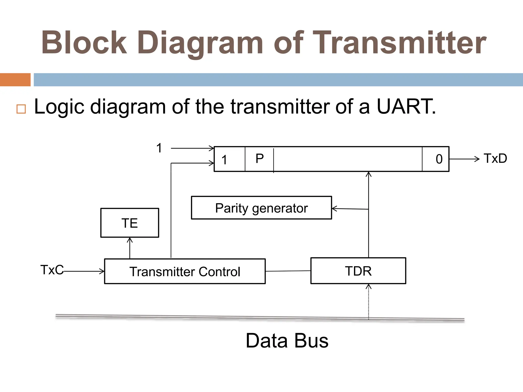
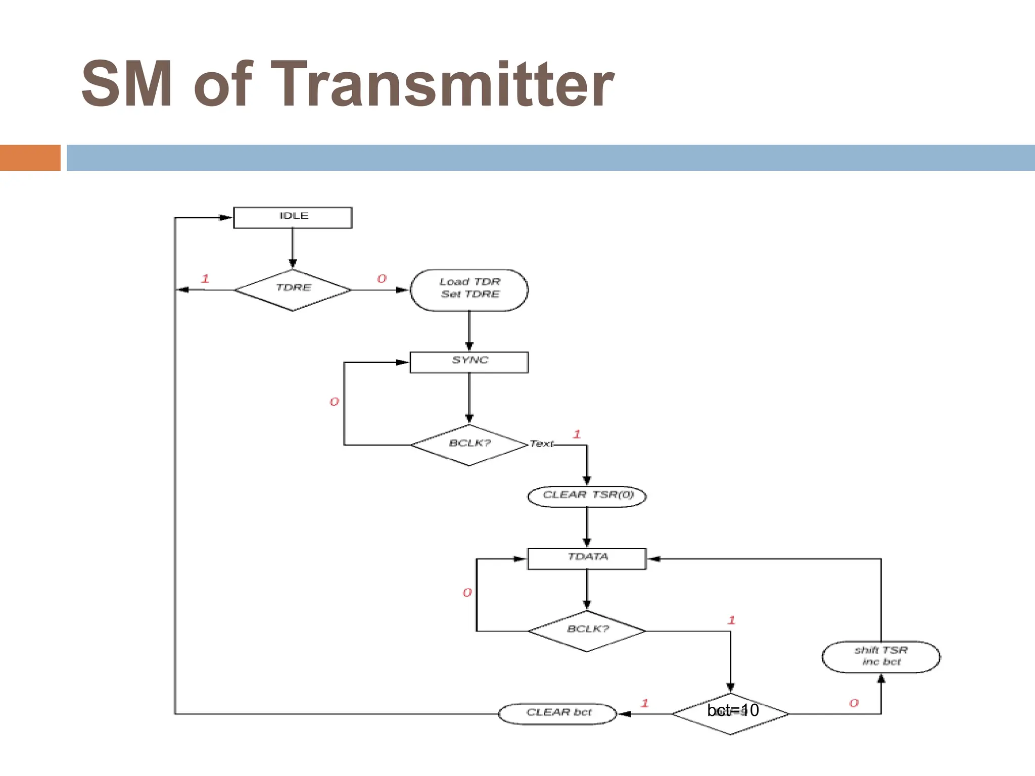
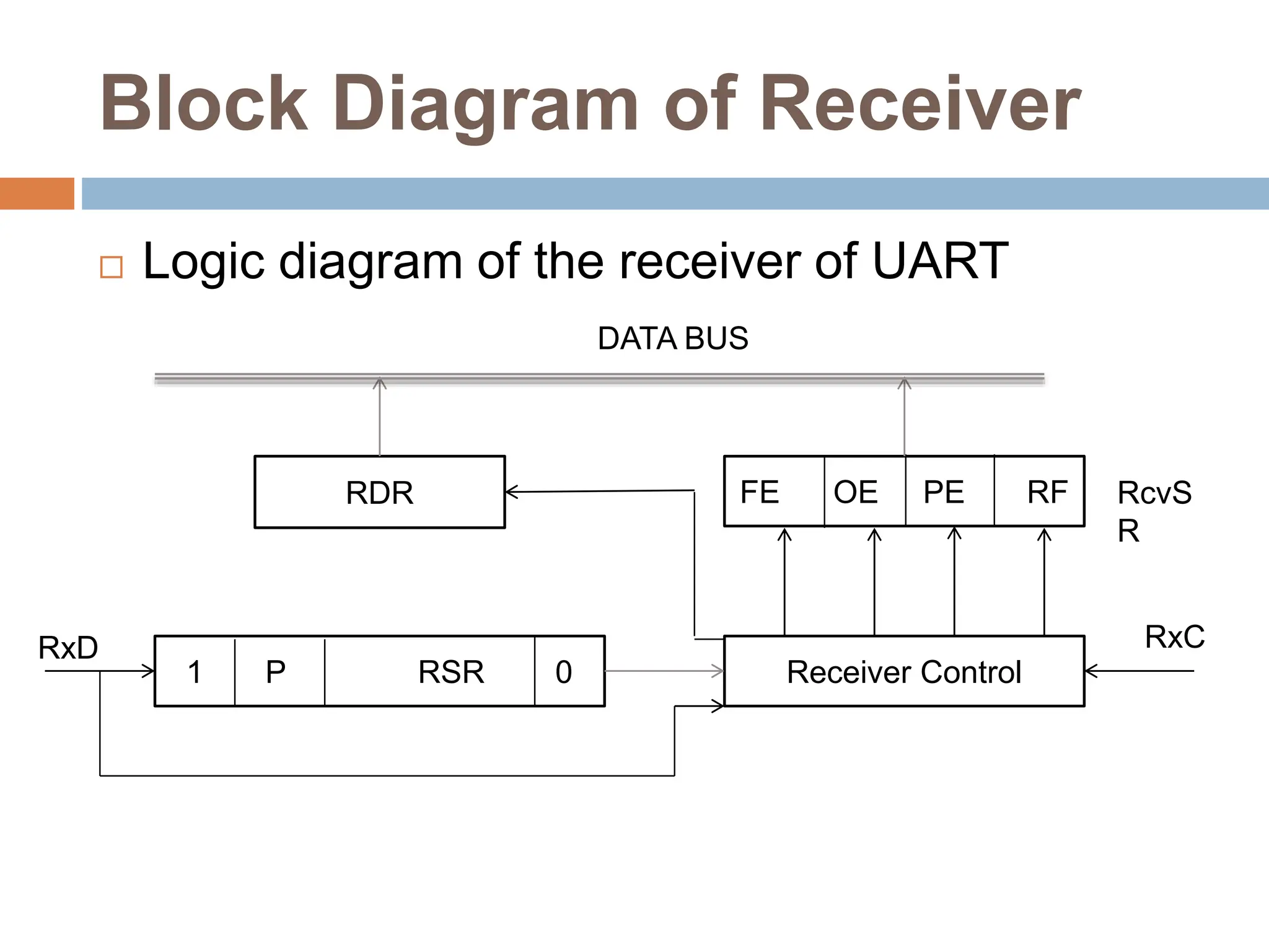
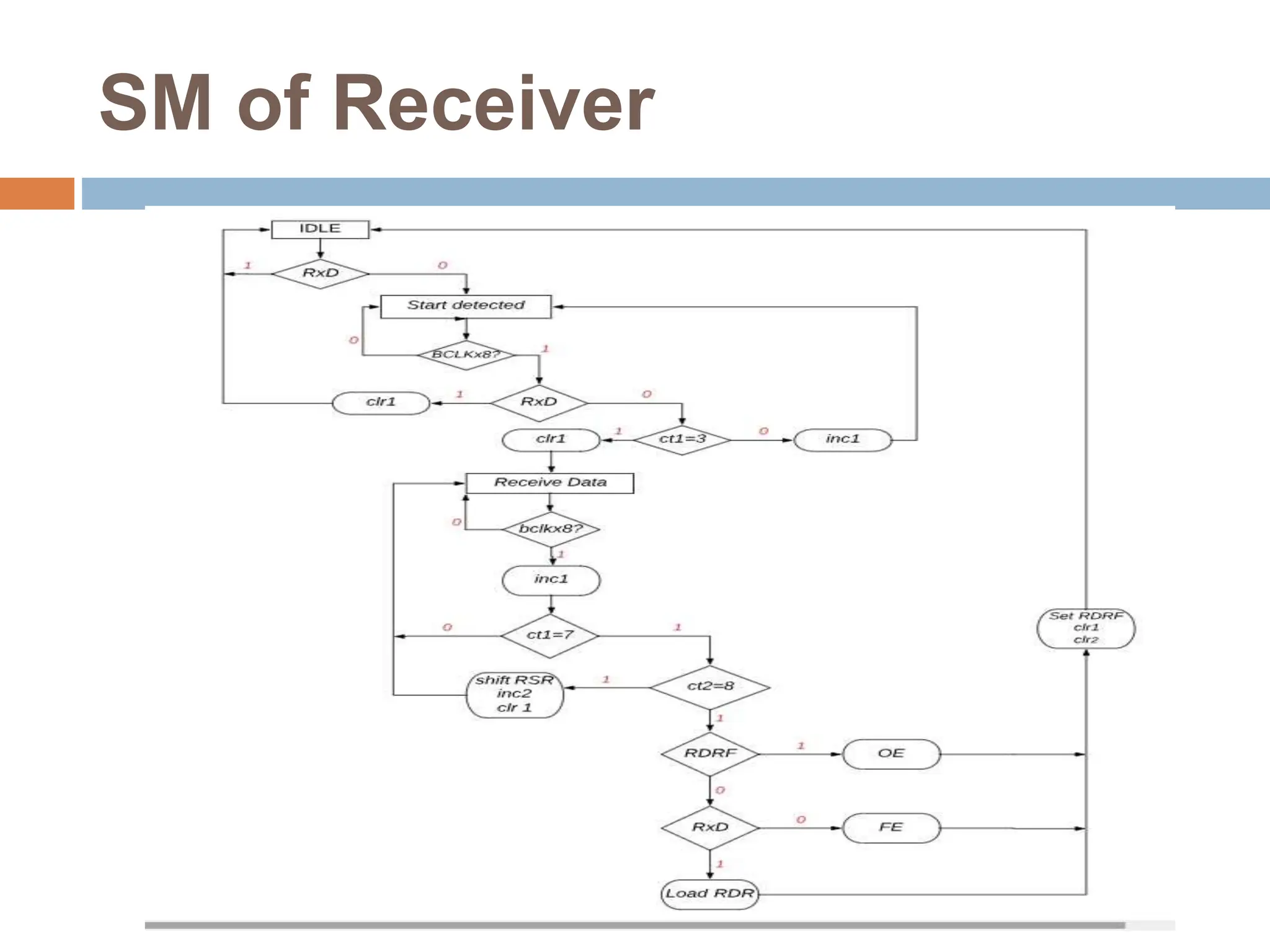
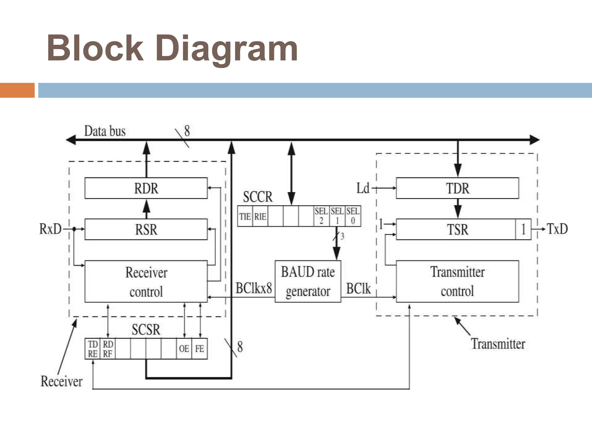
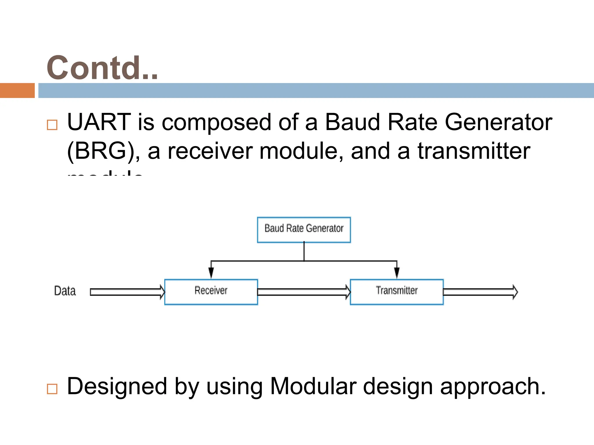
This document outlines the design of a Universal Asynchronous Receiver/Transmitter (UART) module using Verilog HDL. It describes the project flow, introduction to UARTs, design of the baud rate generator, transmitter, receiver, and block diagram. It also includes the simulation results, RTL schematic, technology schematic, utilization reports, and power reports from synthesis and implementation. The design is verified through simulation and the document concludes with discussing future work of verification on FPGA and references related work on UART design.


![RTL Code of Baud Rate
generator
module clk_div(input clk,rst,
output q)
reg [2:0]q1;
always@(posedge clk)
begin if(!rst)
q1<=3'b001;
else
q1<={q1[0],q1[2:1]};
end
assign q=q1[0];
endmodule
module counter_8(input clk,rst,
output reg [7:0]q);
always@(posedge clk)
begin
if(!rst)
q<=8'd0;
else
q<=q+1;
end
endmodule
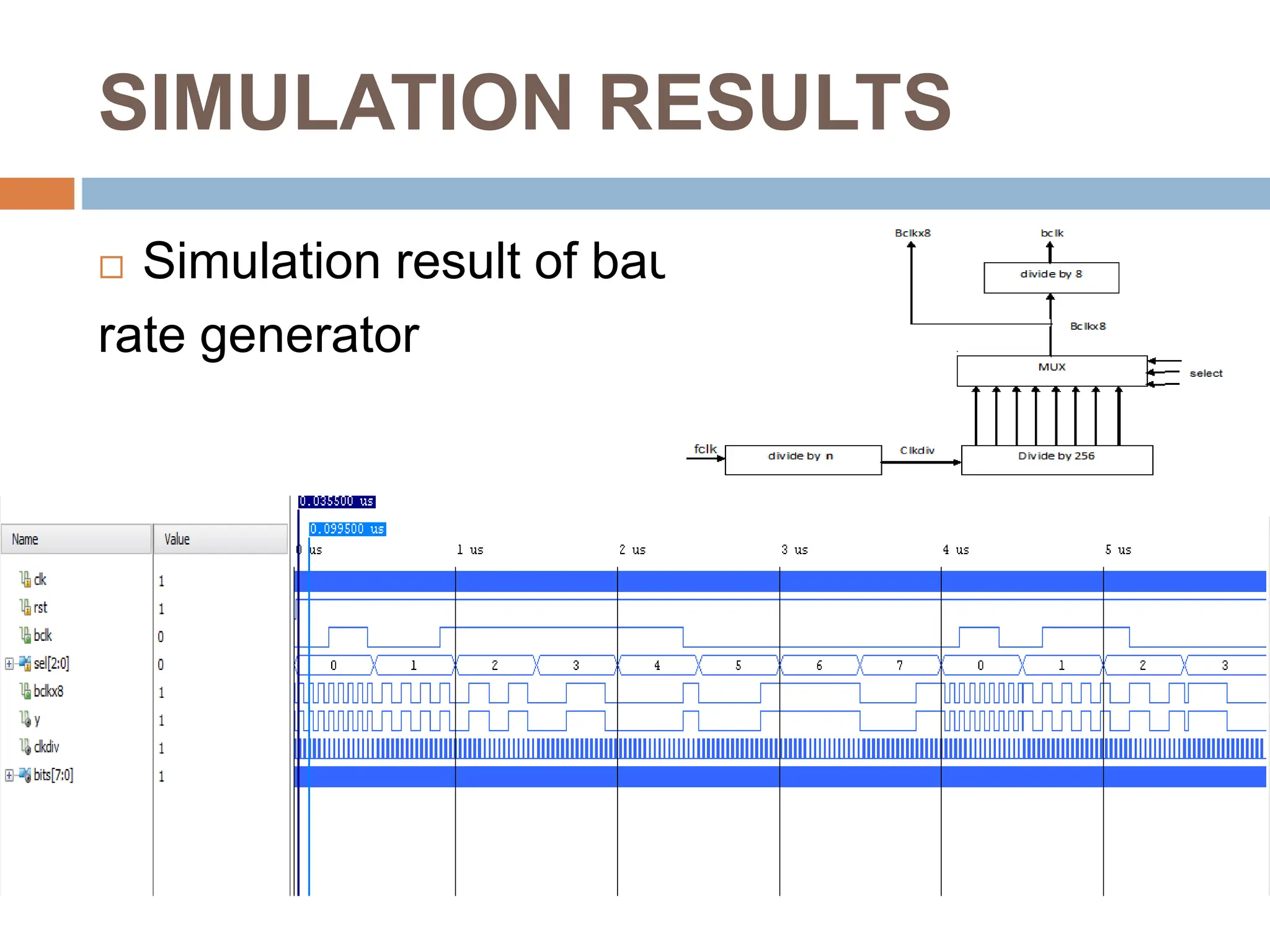
Clock divide by n Divide by 256](https://image.slidesharecdn.com/407841208-modular-uart-240303051111-b8ff3dbe/75/407841208-Modular-UART-pptx-design-and-architecture-9-2048.jpg)
![Contd..
module mux_8(input [7:0]d,
input [2:0]sel,
output reg y);
always@(d,sel)
begin case(sel)
3'b000:y=d[0];
3'b001:y=d[1];
3'b010:y=d[2];
3'b011:y=d[3];
3'b100:y=d[4];
3'b101:y=d[5];
3'b110:y=d[6];
3'b111:y=d[7];
endcase
end
endmodule
module divide_by_8(input clk,rst,
output q);
reg [2:0]count;
always@(posedge clk,negedge
rst)
begin
if(!rst)
count<=3'd0;
else
count<=count+1;
end
assign q=count[2];
endmodule
Multiplexer Divide by 8](https://image.slidesharecdn.com/407841208-modular-uart-240303051111-b8ff3dbe/75/407841208-Modular-UART-pptx-design-and-architecture-10-2048.jpg)