Download free for 30 days
Sign in
Upload
Language (EN)
Support
Business
Mobile
Social Media
Marketing
Technology
Art & Photos
Career
Design
Education
Presentations & Public Speaking
Government & Nonprofit
Healthcare
Internet
Law
Leadership & Management
Automotive
Engineering
Software
Recruiting & HR
Retail
Sales
Services
Science
Small Business & Entrepreneurship
Food
Environment
Economy & Finance
Data & Analytics
Investor Relations
Sports
Spiritual
News & Politics
Travel
Self Improvement
Real Estate
Entertainment & Humor
Health & Medicine
Devices & Hardware
Lifestyle
Change Language
Language
English
Español
Português
Français
Deutsche
Cancel
Save
EN
Uploaded by
marinetacticamary
PPTX, PDF
62 views
presentación de introducción a redes mpls de cisco
introducción a mpls de Cisco
Engineering
◦
Read more
0
Save
Share
Embed
Embed presentation
Download
Download to read offline
1
/ 101
2
/ 101
3
/ 101
4
/ 101
5
/ 101
6
/ 101
7
/ 101
8
/ 101
9
/ 101
10
/ 101
11
/ 101
12
/ 101
13
/ 101
14
/ 101
15
/ 101
16
/ 101
17
/ 101
18
/ 101
19
/ 101
20
/ 101
21
/ 101
22
/ 101
23
/ 101
24
/ 101
25
/ 101
26
/ 101
27
/ 101
28
/ 101
29
/ 101
30
/ 101
31
/ 101
32
/ 101
33
/ 101
34
/ 101
35
/ 101
36
/ 101
37
/ 101
38
/ 101
39
/ 101
40
/ 101
41
/ 101
42
/ 101
43
/ 101
44
/ 101
45
/ 101
46
/ 101
47
/ 101
48
/ 101
49
/ 101
50
/ 101
51
/ 101
52
/ 101
53
/ 101
54
/ 101
55
/ 101
56
/ 101
57
/ 101
58
/ 101
59
/ 101
60
/ 101
61
/ 101
62
/ 101
63
/ 101
64
/ 101
65
/ 101
66
/ 101
67
/ 101
68
/ 101
69
/ 101
70
/ 101
71
/ 101
72
/ 101
73
/ 101
74
/ 101
75
/ 101
76
/ 101
77
/ 101
78
/ 101
79
/ 101
80
/ 101
81
/ 101
82
/ 101
83
/ 101
84
/ 101
85
/ 101
86
/ 101
87
/ 101
88
/ 101
89
/ 101
90
/ 101
91
/ 101
92
/ 101
93
/ 101
94
/ 101
95
/ 101
96
/ 101
97
/ 101
98
/ 101
99
/ 101
100
/ 101
101
/ 101
More Related Content
PDF
MPLS Presentation
by
Unni Kannan VijayaKumar
PDF
mpls-lecture.pdf
by
YagneshDodiya2
PDF
MPLS Concepts and Fundamentals
by
Shawn Zandi
PPT
Mpls Services
by
Kristof De Brouwer
PDF
Implementing cisco mpls
by
Matiullah Jamil
PDF
QOS of MPLS
by
IOSR Journals
PDF
J010136172
by
IOSR Journals
PPT
MPLS-jpl.ppt
by
demon667714
MPLS Presentation
by
Unni Kannan VijayaKumar
mpls-lecture.pdf
by
YagneshDodiya2
MPLS Concepts and Fundamentals
by
Shawn Zandi
Mpls Services
by
Kristof De Brouwer
Implementing cisco mpls
by
Matiullah Jamil
QOS of MPLS
by
IOSR Journals
J010136172
by
IOSR Journals
MPLS-jpl.ppt
by
demon667714
Similar to presentación de introducción a redes mpls de cisco
PPT
Digital network lecturer3
by
Jumaan Ally Mohamed
PDF
mpls.pdf
by
Huynh MVT
PPSX
MPLS
by
Md Khaleduzzaman
PDF
VPN Using MPLS Technique
by
Ahmad Atta
PPT
Mpls
by
rahulvce07
PPT
MPLS_cisco.ppt
by
ssuserd0c720
PPTX
Presentation2 RAMPRASAD134.pptxhahshshshhs
by
newshunt535
PPTX
An introduction to MPLS networks and applications
by
Shawn Zandi
PPT
Mpls Traffic Engineering ppt
by
Nitin Gehlot
PDF
MPLS Lecture1(H)-102020.pdf
by
MulugetaTsehay1
PPT
Broadband Network Presentation
by
Muhammad Faisal
PDF
MPLS + BGP Presentation
by
Gino McCarty
PPTX
MPLS DWDM.pptxxxxxxxxxxxxxxxxxxxxxxxxxxc
by
1706khushiyadav
PDF
Advanced Topics and Future Directions in MPLS
by
Cisco Canada
PPT
Mpls by vidhu
by
CU
PDF
01 introduction to mpls
by
Achmad Mardiansyah
PPT
Mpls vpn
by
rel comm
PPTX
MPLS (Multi-Protocol Label Switching)
by
NetProtocol Xpert
PDF
cisco-mpls-tp-solutions-moustafa-kattan.pdf
by
Geneva Business School Myanmar Campus
PPT
MPLS.ppt
by
sridharsiva5
Digital network lecturer3
by
Jumaan Ally Mohamed
mpls.pdf
by
Huynh MVT
MPLS
by
Md Khaleduzzaman
VPN Using MPLS Technique
by
Ahmad Atta
Mpls
by
rahulvce07
MPLS_cisco.ppt
by
ssuserd0c720
Presentation2 RAMPRASAD134.pptxhahshshshhs
by
newshunt535
An introduction to MPLS networks and applications
by
Shawn Zandi
Mpls Traffic Engineering ppt
by
Nitin Gehlot
MPLS Lecture1(H)-102020.pdf
by
MulugetaTsehay1
Broadband Network Presentation
by
Muhammad Faisal
MPLS + BGP Presentation
by
Gino McCarty
MPLS DWDM.pptxxxxxxxxxxxxxxxxxxxxxxxxxxc
by
1706khushiyadav
Advanced Topics and Future Directions in MPLS
by
Cisco Canada
Mpls by vidhu
by
CU
01 introduction to mpls
by
Achmad Mardiansyah
Mpls vpn
by
rel comm
MPLS (Multi-Protocol Label Switching)
by
NetProtocol Xpert
cisco-mpls-tp-solutions-moustafa-kattan.pdf
by
Geneva Business School Myanmar Campus
MPLS.ppt
by
sridharsiva5
Recently uploaded
PPTX
ISO 13485.2016 Awareness's Training material
by
PrakashSivan
PPTX
Value engineering and cost analysis with case study
by
hp9879098082
PDF
Computer Graphics Fundamentals (v0p1) - DannyJiang
by
Danny Jiang
PDF
Chemical Hazards at Workplace – Types, Properties & Exposure Routes, CORE-EHS
by
CORE EHS
PPT
Momentum and collisions in physics or engineering
by
azizrahmanhakimi
PPT
Integer , Goal and Non linear Programming Model
by
OcheriCyril2
PDF
CME397 SURFACE ENGINEERING UNIT 2 FULL NOTES
by
karthi keyan
PDF
PROBLEM SLOVING AND PYTHON PROGRAMMING UNIT 3.pdf
by
A R SIVANESH M.E., QIP-PG (Cyber Security)., (Ph.D)
PPTX
Day 3 Module 5_Optical fiber Network (operation and management).pptx
by
SachayaG
PDF
Computer Network Lab Manual ssit -kavya r.pdf or Computer Network Lab Manual ...
by
kavya R
PDF
Decision-Support-Systems-and-Decision-Making-Processes.pdf
by
PatankarNikhil
PPTX
This Bearing Didn’t Fail Suddenly — How Vibration Data Predicts Failure Month...
by
MaintWiz Technologies Private Limited
PPTX
Fitting Infiltration Models to Infiltration using Excel (1).pptx
by
TomNickoRivera1
PPT
Cloud computing-1.ppt presentation preview
by
MohanaPriya780617
PDF
Infinite Sequence and Series: It Includes basic Sequence and Series
by
DynamicDomain1
PPTX
1.Module 4-Clamping of jigs and fixtures for manufacturing.pptx
by
condieki
PPTX
Introduction to AI and Applications Module-4.pptx
by
KalaiselviSubramania2
PDF
Model QP 2025 scheme Q &A- Module 1 and 2.pdf
by
SURESHA V
PPTX
Presentation-WPS Office.pptx afgouvhyhgfccf
by
EndaleTimerga
PPTX
Unit 1_Importance of modelling(Object oriented concepts).pptx
by
Vidyaranichougule
ISO 13485.2016 Awareness's Training material
by
PrakashSivan
Value engineering and cost analysis with case study
by
hp9879098082
Computer Graphics Fundamentals (v0p1) - DannyJiang
by
Danny Jiang
Chemical Hazards at Workplace – Types, Properties & Exposure Routes, CORE-EHS
by
CORE EHS
Momentum and collisions in physics or engineering
by
azizrahmanhakimi
Integer , Goal and Non linear Programming Model
by
OcheriCyril2
CME397 SURFACE ENGINEERING UNIT 2 FULL NOTES
by
karthi keyan
PROBLEM SLOVING AND PYTHON PROGRAMMING UNIT 3.pdf
by
A R SIVANESH M.E., QIP-PG (Cyber Security)., (Ph.D)
Day 3 Module 5_Optical fiber Network (operation and management).pptx
by
SachayaG
Computer Network Lab Manual ssit -kavya r.pdf or Computer Network Lab Manual ...
by
kavya R
Decision-Support-Systems-and-Decision-Making-Processes.pdf
by
PatankarNikhil
This Bearing Didn’t Fail Suddenly — How Vibration Data Predicts Failure Month...
by
MaintWiz Technologies Private Limited
Fitting Infiltration Models to Infiltration using Excel (1).pptx
by
TomNickoRivera1
Cloud computing-1.ppt presentation preview
by
MohanaPriya780617
Infinite Sequence and Series: It Includes basic Sequence and Series
by
DynamicDomain1
1.Module 4-Clamping of jigs and fixtures for manufacturing.pptx
by
condieki
Introduction to AI and Applications Module-4.pptx
by
KalaiselviSubramania2
Model QP 2025 scheme Q &A- Module 1 and 2.pdf
by
SURESHA V
Presentation-WPS Office.pptx afgouvhyhgfccf
by
EndaleTimerga
Unit 1_Importance of modelling(Object oriented concepts).pptx
by
Vidyaranichougule
presentación de introducción a redes mpls de cisco
1.
Santanu Dasgupta santanu@cisco.com Introduction to
MPLS
2.
Goals of this
Session 2 © 2010 Cisco and/or its affiliates. All rights reserved. Understand history and business drivers for MPLS Learn about MPLS customer and market segments Understand the problems MPLS is addressing Understand benefits of deploying MPLS Understand the major MPLS technology components Learn the basics of MPLS technology Understand typical applications of MPLS
3.
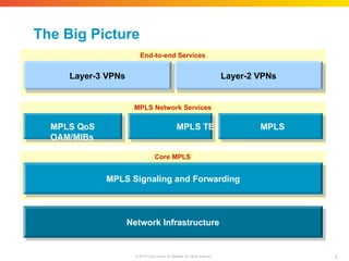
The Big Picture Core
Core dge Core Core MPLS Signaling a d Forwarding MPLS Network Services End-to-end MPLS VPN Services MPLS in Core Network End-to-end MPLS-enabled Services Edge E Edge Edge Layer-3 VPNs n Layer-2 VPNs Edge Edge MPLS QoS MPLS TE MPLS OAM/MIBs Edge Edge Network Infrastructure MPLS Signaling and Forwarding Layer-3 VPNs Layer-2 VPNs MPLS QoS MPLS TE MPLS OAM/MIBs End-to-end Services MPLS Network Services Core MPLS 3 © 2010 Cisco and/or its affiliates. All rights reserved.
4.
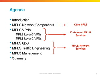
Agenda Introduction MPLS
Network Components MPLS VPNs MPLS Layer-3 VPNs MPLS Layer-2 VPNs MPLS QoS MPLS Traffic Engineering MPLS Management Summary Core MPLS End-to-end MPLS Services MPLS Network Services 4 © 2010 Cisco and/or its affiliates. All rights reserved.
5.
Cisco Public Presentation_ID ©
2010 Cisco and/or its affiliates. All rights reserved. 5 Introduction The business drivers for MPLS
6.
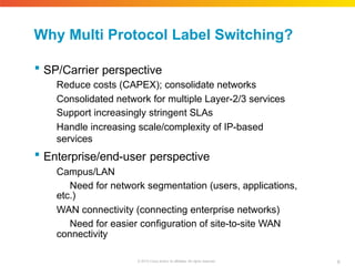
Why Multi Protocol
Label Switching? 6 © 2010 Cisco and/or its affiliates. All rights reserved. SP/Carrier perspective Reduce costs (CAPEX); consolidate networks Consolidated network for multiple Layer-2/3 services Support increasingly stringent SLAs Handle increasing scale/complexity of IP-based services Enterprise/end-user perspective Campus/LAN Need for network segmentation (users, applications, etc.) WAN connectivity (connecting enterprise networks) Need for easier configuration of site-to-site WAN connectivity
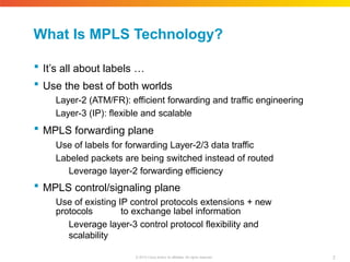
7.
What Is MPLS
Technology? 7 © 2010 Cisco and/or its affiliates. All rights reserved. It’s all about labels … Use the best of both worlds Layer-2 (ATM/FR): efficient forwarding and traffic engineering Layer-3 (IP): flexible and scalable MPLS forwarding plane Use of labels for forwarding Layer-2/3 data traffic Labeled packets are being switched instead of routed Leverage layer-2 forwarding efficiency MPLS control/signaling plane Use of existing IP control protocols extensions + new protocols to exchange label information Leverage layer-3 control protocol flexibility and scalability
8.
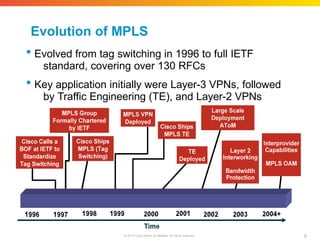
Evolution of MPLS
Evolved from tag switching in 1996 to full IETF standard, covering over 130 RFCs Key application initially were Layer-3 VPNs, followed by Traffic Engineering (TE), and Layer-2 VPNs 8 © 2010 Cisco and/or its affiliates. All rights reserved.
9.
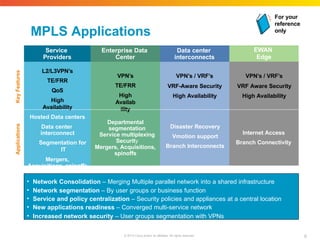
MPLS Applications EWAN Edge Service Providers Enterprise Data Center Data
center interconnects L2/L3VPN’s TE/FRR QoS High Availability VPN’s / VRF’s VRF-Aware Security High Availability Hosted Data centers Data center interconnect Segmentation for IT Mergers, Acquisitions, spinoffs Applications Key Features Departmental segmentation Service multiplexing Security Mergers, Acquisitions, spinoffs Disaster Recovery Vmotion support Branch Interconnects Internet Access Branch Connectivity VPN’s / VRF’s VRF Aware Security High Availability VPN’s TE/FRR High Availab ility • Network Consolidation – Merging Multiple parallel network into a shared infrastructure • Network segmentation – By user groups or business function • Service and policy centralization – Security policies and appliances at a central location • New applications readiness – Converged multi-service network • Increased network security – User groups segmentation with VPNs For your reference only 9 © 2010 Cisco and/or its affiliates. All rights reserved.
10.
Enterprise MPLS Customers 10 ©
2010 Cisco and/or its affiliates. All rights reserved. Two types of enterprise customers for MPLS technology MPLS indirectly used as subscribed WAN service Enterprise subscribes to WAN connectivity data service offered by external Service Provider Data connectivity service implemented by Service Provider via MPLS VPN technology (e.g., layer-2 and layer-3 VPNs) VPN Service can be managed or unmanaged MPLS used as part of self managed network Enterprise deploys MPLS in it’s own network Enterprise manages it’s own MPLS-based network
11.
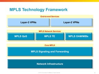
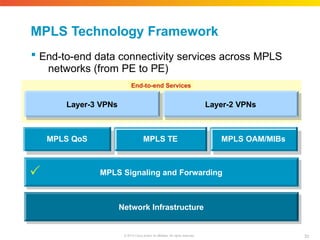
MPLS Technology Framework Network
Infrastructure MPLS Signaling and Forwarding Layer-3 VPNs Layer-2 VPNs MPLS QoS MPLS TE MPLS OAM/MIBs End-to-end Services MPLS Network Services Core MPLS 11 © 2010 Cisco and/or its affiliates. All rights reserved.
12.
Cisco Public Presentation_ID ©
2010 Cisco and/or its affiliates. All rights reserved. 12 MPLS Technology Components Basic building blocks of MPLS
13.
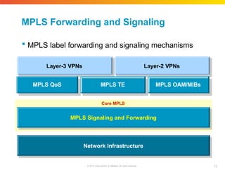
MPLS Forwarding and
Signaling MPLS label forwarding and signaling mechanisms Network Infrastructure MPLS Signaling and Forwarding Layer-3 VPNs Layer-2 VPNs MPLS QoS MPLS TE MPLS OAM/MIBs Core MPLS 13 © 2010 Cisco and/or its affiliates. All rights reserved.
14.
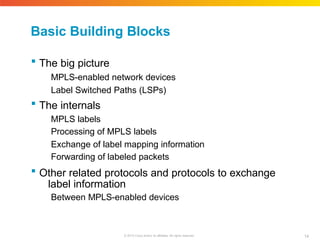
Basic Building Blocks 14 ©
2010 Cisco and/or its affiliates. All rights reserved. The big picture MPLS-enabled network devices Label Switched Paths (LSPs) The internals MPLS labels Processing of MPLS labels Exchange of label mapping information Forwarding of labeled packets Other related protocols and protocols to exchange label information Between MPLS-enabled devices
15.
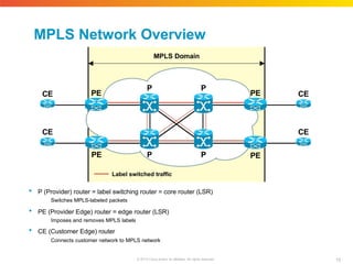
MPLS Domain MPLS Network
Overview CE CE CE CE Label switched traffic P (Provider) router = label switching router = core router (LSR) Switches MPLS-labeled packets PE (Provider Edge) router = edge router (LSR) Imposes and removes MPLS labels CE (Customer Edge) router Connects customer network to MPLS network P 15 © 2010 Cisco and/or its affiliates. All rights reserved. P P P PE PE PE PE
16.
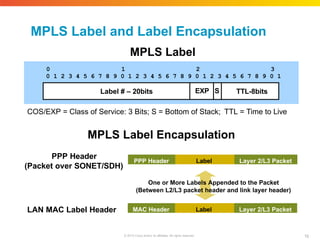
MPLS Label and
Label Encapsulation COS/EXP = Class of Service: 3 Bits; S = Bottom of Stack; TTL = Time to Live 0 1 2 3 0 1 2 3 4 5 6 7 8 9 0 1 2 3 4 5 6 7 8 9 0 1 2 3 4 5 6 7 8 9 0 1 Label # – 20bits EXP S TTL-8bits MPLS Label Label 16 © 2010 Cisco and/or its affiliates. All rights reserved. PPP Header Layer 2/L3 Packet PPP Header (Packet over SONET/SDH) MPLS Label Encapsulation One or More Labels Appended to the Packet (Between L2/L3 packet header and link layer header) LAN MAC Label Header Label MAC Header Layer 2/L3 Packet
17.
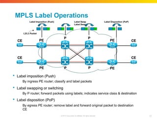
MPLS Label Operations Label
Imposition (Push) Label Swap Label Swap Label imposition (Push) By ingress PE router; classify and label packets Label swapping or switching By P router; forward packets using labels; indicates service class & destination Label disposition (PoP) By egress PE router; remove label and forward original packet to destination CE CE 17 © 2010 Cisco and/or its affiliates. All rights reserved. CE CE CE PE PE PE P P L1 L2/L3 Packet L1 L2 P L2 L3 PE L3 Label Disposition (PoP) P
18.
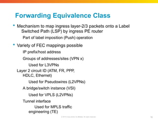
Forwarding Equivalence Class 18 ©
2010 Cisco and/or its affiliates. All rights reserved. Mechanism to map ingress layer-2/3 packets onto a Label Switched Path (LSP) by ingress PE router Part of label imposition (Push) operation Variety of FEC mappings possible IP prefix/host address Groups of addresses/sites (VPN x) Used for L3VPNs Layer 2 circuit ID (ATM, FR, PPP, HDLC, Ethernet) Used for Pseudowires (L2VPNs) A bridge/switch instance (VSI) Used for VPLS (L2VPNs) Tunnel interface Used for MPLS traffic engineering (TE)
19.
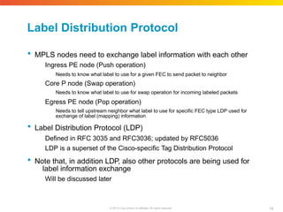
Label Distribution Protocol Will
be discussed later 19 © 2010 Cisco and/or its affiliates. All rights reserved. MPLS nodes need to exchange label information with each other Ingress PE node (Push operation) Needs to know what label to use for a given FEC to send packet to neighbor Core P node (Swap operation) Needs to know what label to use for swap operation for incoming labeled packets Egress PE node (Pop operation) Needs to tell upstream neighbor what label to use for specific FEC type LDP used for exchange of label (mapping) information Label Distribution Protocol (LDP) Defined in RFC 3035 and RFC3036; updated by RFC5036 LDP is a superset of the Cisco-specific Tag Distribution Protocol Note that, in addition LDP, also other protocols are being used for label information exchange
20.
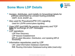
Some More LDP
Details Assigns, distributes, and installs (in forwarding) labels for prefixes advertised by unicast routing protocols OSPF, IS-IS, EIGRP, etc. Also used for Pseudowire/PW (VC) signaling Used for L2VPN control plane signaling Uses UDP (port 646) for session discovery and TCP (port 646) for exchange of LDP messages LDP operations LDP Peer Discovery LDP Session Establishment MPLS Label Allocation, Distribution, and Updating MPLS forwarding Information repositories used by LDP LIB: Label Information Database (read/write) RIB: Routing Information Database/routing table (read-only) For your reference only 20 © 2010 Cisco and/or its affiliates. All rights reserved.
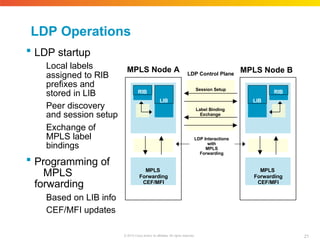
21.
LDP Control Plane MPLS
Node A LDP Operations LDP startup Local labels assigned to RIB prefixes and stored in LIB Peer discovery and session setup Exchange of MPLS label bindings Programming of MPLS forwarding Based on LIB info CEF/MFI updates MPLS Node B Session Setup Label Binding Exchange MPLS Forwarding CEF/MFI RIB LIB MPLS Forwarding CEF/MFI LDP Interactions with MPLS Forwarding LIB RIB 21 © 2010 Cisco and/or its affiliates. All rights reserved.
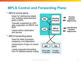
22.
MPLS Control and
Forwarding Plane MPLS control plane Used for distributing labels and building label-switched paths (LSPs) Typically supported by LDP; also supported via RSVP and BGP Labels define destination and service MPLS forwarding plane Used for label imposition, swapping, and disposition Independent of type of control plane Labels separate forwarding from IP address-based routing LIB Routing Updates/ Adjacencies MFI MPLS Traffic Forwarding FIB MPLS Process Routing Process RIB Label Binding Updates/ Adjacencies IP Traffic Forwarding 22 © 2010 Cisco and/or its affiliates. All rights reserved.
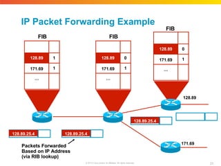
23.
IP Packet Forwarding
Example 128.89 171.69 128.89.25.4 128.89.25.4 128.89.25.4 Packets Forwarded Based on IP Address (via RIB lookup) 128.89 1 171.69 1 … 128.89 0 171.69 1 … 128.89 0 171.69 1 … 23 © 2010 Cisco and/or its affiliates. All rights reserved. FIB FIB FIB
24.
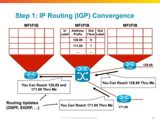
Step 1: IP
Routing (IGP) Convergence 128.89 171.69 In Label Address Prefix Out I’face Out Label 128.89 0 171.69 1 … … You Can Reach 171.69 Thru Me You Can Reach 128.89 and 171.69 Thru Me Routing Updates (OSPF, EIGRP, …) You Can Reach 128.89 Thru Me MFI/FIB MFI/FIB MFI/FIB 24 © 2010 Cisco and/or its affiliates. All rights reserved.
25.
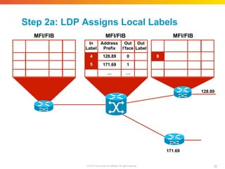
128.89 171.69 In Label Address Prefix Out I’face Out Label 4 5 128.89 0 171.69 1 …
… 25 © 2010 Cisco and/or its affiliates. All rights reserved. 9 Step 2a: LDP Assigns Local Labels MFI/FIB MFI/FIB MFI/FIB
26.
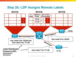
128.89 Use Label 9
for 128.89 Use Label 4 for 128.89 and Use Label 5 for 171.69 Label Distribution Protocol (LDP) (Downstream Allocation) 171.69 Use Label 7 for 171.69 4 5 In Label Address Prefix Out I’face Out Label 128.89 0 9 7 171.69 1 … … 26 © 2010 Cisco and/or its affiliates. All rights reserved. Step 2b: LDP Assigns Remote Labels MFI/FIB MFI/FIB MFI/FIB
27.
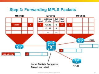
128.89.25.4 4 9 Label Switch
Forwards Based on Label 128.89 171.69 128.89 4 In Label Address Prefix Out I’face Out Label 4 128.89 0 9 171.69 1 … … 27 © 2010 Cisco and/or its affiliates. All rights reserved. 9 Step 3: Forwarding MPLS Packets MFI/FIB MFI/FIB MFI/FIB
28.
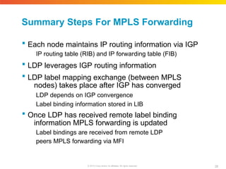
Summary Steps For
MPLS Forwarding 28 © 2010 Cisco and/or its affiliates. All rights reserved. Each node maintains IP routing information via IGP IP routing table (RIB) and IP forwarding table (FIB) LDP leverages IGP routing information LDP label mapping exchange (between MPLS nodes) takes place after IGP has converged LDP depends on IGP convergence Label binding information stored in LIB Once LDP has received remote label binding information MPLS forwarding is updated Label bindings are received from remote LDP peers MPLS forwarding via MFI
29.
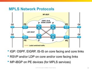
MPLS Network Protocols
IGP: OSPF, EIGRP, IS-IS on core facing and core links RSVP and/or LDP on core and/or core facing links MP-iBGP on PE devices (for MPLS services) Label switched traffic P 29 © 2010 Cisco and/or its affiliates. All rights reserved. P P P PE PE PE PE OSPF, IS-IS, EIGRP, EIGRP LDP, RSVP MP-iBGP CE CE CE CE
30.
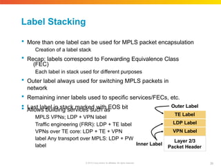
Label Stacking More
than one label can be used for MPLS packet encapsulation Creation of a label stack Recap: labels correspond to Forwarding Equivalence Class (FEC) Each label in stack used for different purposes Outer label always used for switching MPLS packets in network Remaining inner labels used to specific services/FECs, etc. Last label in stack marked with EOS bit Allows building services such as MPLS VPNs; LDP + VPN label Traffic engineering (FRR): LDP + TE label VPNs over TE core: LDP + TE + VPN label Any transport over MPLS: LDP + PW label Inner Label Outer Label TE Label LDP Label VPN Label Layer 2/3 Packet Header 30 © 2010 Cisco and/or its affiliates. All rights reserved.
31.
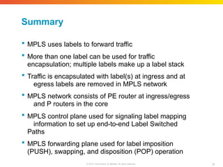
Summary 31 © 2010 Cisco
and/or its affiliates. All rights reserved. MPLS uses labels to forward traffic More than one label can be used for traffic encapsulation; multiple labels make up a label stack Traffic is encapsulated with label(s) at ingress and at egress labels are removed in MPLS network MPLS network consists of PE router at ingress/egress and P routers in the core MPLS control plane used for signaling label mapping information to set up end-to-end Label Switched Paths MPLS forwarding plane used for label imposition (PUSH), swapping, and disposition (POP) operation
32.
Cisco Public Presentation_ID ©
2010 Cisco and/or its affiliates. All rights reserved. 32 MPLS VPNs Overviews
33.
MPLS Technology Framework Network
Infrastructure MPLS Signaling and Forwarding Layer-3 VPNs Layer-2 VPNs MPLS QoS MPLS TE MPLS OAM/MIBs End-to-end Services 33 © 2010 Cisco and/or its affiliates. All rights reserved. End-to-end data connectivity services across MPLS networks (from PE to PE)
34.
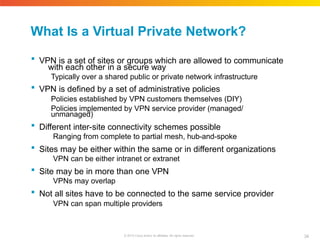
What Is a
Virtual Private Network? 34 © 2010 Cisco and/or its affiliates. All rights reserved. VPN is a set of sites or groups which are allowed to communicate with each other in a secure way Typically over a shared public or private network infrastructure VPN is defined by a set of administrative policies Policies established by VPN customers themselves (DIY) Policies implemented by VPN service provider (managed/ unmanaged) Different inter-site connectivity schemes possible Ranging from complete to partial mesh, hub-and-spoke Sites may be either within the same or in different organizations VPN can be either intranet or extranet Site may be in more than one VPN VPNs may overlap Not all sites have to be connected to the same service provider VPN can span multiple providers
35.
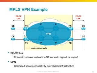
MPLS VPN Example
PE-CE link Connect customer network to SP network; layer-2 or layer-3 VPN Dedicated secure connectivity over shared infrastructure Label switched traffic P 35 © 2010 Cisco and/or its affiliates. All rights reserved. P P P PE PE PE PE CE CE CE CE VPN PE-CE Link PE-CE Link
36.
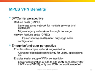
MPLS VPN Benefits 36 ©
2010 Cisco and/or its affiliates. All rights reserved. SP/Carrier perspective Reduce costs (CAPEX) Leverage same network for multiple services and customers Migrate legacy networks onto single converged network Reduce costs (OPEX) Easier service enablement; only edge node configuration Enterprise/end-user perspective Enables site/campus network segmentation Allows for dedicated connectivity for users, applications, etc. Enables easier setup of WAN connectivity Easier configuration of site-to-site WAN connectivity (for L3VPN and VPLS); only one WAN connection needed
37.
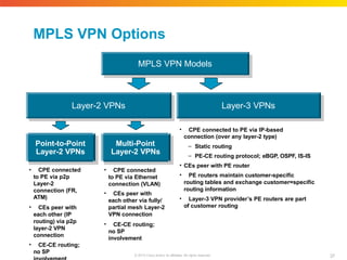
MPLS VPN Models MPLS
VPN Options • CPE connected to PE via IP-based connection (over any layer-2 type) – Static routing – PE-CE routing protocol; eBGP, OSPF, IS-IS • CEs peer with PE router • PE routers maintain customer-specific routing tables and exchange customer=specific routing information • Layer-3 VPN provider’s PE routers are part of customer routing Layer-3 VPNs Layer-2 VPNs Point-to-Point Layer-2 VPNs Multi-Point Layer-2 VPNs • CPE connected to PE via p2p Layer-2 connection (FR, ATM) • CEs peer with each other (IP routing) via p2p layer-2 VPN connection • CE-CE routing; no SP • CPE connected to PE via Ethernet connection (VLAN) • CEs peer with each other via fully/ partial mesh Layer-2 VPN connection • CE-CE routing; no SP involvement 37 © 2010 Cisco and/or its affiliates. All rights reserved.
38.
Cisco Public Presentation_ID ©
2010 Cisco and/or its affiliates. All rights reserved. 38 MPLS Layer-3 VPNs Technology Overview and Applications
39.
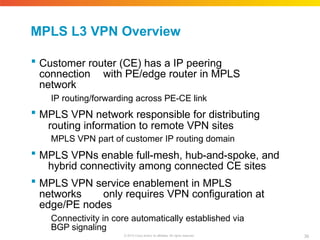
MPLS L3 VPN
Overview 39 © 2010 Cisco and/or its affiliates. All rights reserved. Customer router (CE) has a IP peering connection with PE/edge router in MPLS network IP routing/forwarding across PE-CE link MPLS VPN network responsible for distributing routing information to remote VPN sites MPLS VPN part of customer IP routing domain MPLS VPNs enable full-mesh, hub-and-spoke, and hybrid connectivity among connected CE sites MPLS VPN service enablement in MPLS networks only requires VPN configuration at edge/PE nodes Connectivity in core automatically established via BGP signaling
40.
MPLS L3 VPN
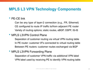
Technology Components 40 © 2010 Cisco and/or its affiliates. All rights reserved. PE-CE link Can be any type of layer-2 connection (e.g., FR, Ethernet) CE configured to route IP traffic to/from adjacent PE router Variety of routing options; static routes, eBGP, OSPF, IS-IS MPLS L3VPN Control Plane Separation of customer routing via virtual VPN routing table In PE router: customer I/Fs connected to virtual routing table Between PE routers: customer routes exchanged via BGP MPLS L3VPN Forwarding Plane Separation of customer VPN traffic via additional VPN label VPN label used by receiving PE to identify VPN routing table
41.
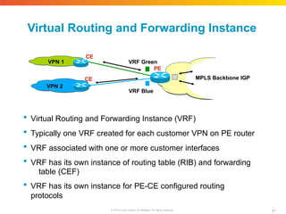
Virtual Routing and
Forwarding Instance VRF Blue Virtual Routing and Forwarding Instance (VRF) Typically one VRF created for each customer VPN on PE router VRF associated with one or more customer interfaces VRF has its own instance of routing table (RIB) and forwarding table (CEF) VRF has its own instance for PE-CE configured routing protocols CE VRF Green PE CE VPN 2 VPN 1 MPLS Backbone IGP 41 © 2010 Cisco and/or its affiliates. All rights reserved.
42.
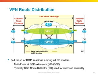
VPN Route Distribution P P P P PE PE
PE PE CE CE CE CE Customer Route Exchange Customer Route Exchange VPN Route Exchange BGP RR VRF VRF VPN 2 VRF VRF VPN 1 Label switched traffic MP- iBGP Session Full mesh of BGP sessions among all PE routers Multi-Protocol BGP extensions (MP-iBGP) Typically BGP Route Reflector (RR) used for improved scalability 42 © 2010 Cisco and/or its affiliates. All rights reserved.
43.
VPN Control Plane
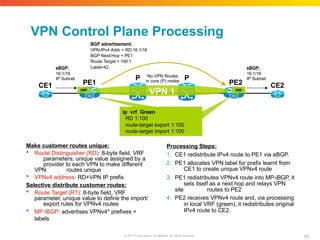
Processing Make customer routes unique: Route Distinguisher (RD): 8-byte field, VRF parameters; unique value assigned by a provider to each VPN to make different VPN routes unique VPNv4 address: RD+VPN IP prefix Selective distribute customer routes: Route Target (RT): 8-byte field, VRF parameter, unique value to define the import/ export rules for VPNv4 routes MP-iBGP: advertises VPNv4* prefixes + labels Processing Steps: 1. CE1 redistribute IPv4 route to PE1 via eBGP. 2. PE1 allocates VPN label for prefix learnt from CE1 to create unique VPNv4 route 3. PE1 redistributes VPNv4 route into MP-iBGP, it sets itself as a next hop and relays VPN site routes to PE2 4. PE2 receives VPNv4 route and, via processing in local VRF (green), it redistributes original IPv4 route to CE2. P P PE1 PE2 CE1 CE2 ip vrf Green RD 1:100 route-target export 1:100 route-target import 1:100 eBGP: 16.1/16 IP Subnet BGP advertisement: VPN-IPv4 Addr = RD:16.1/16 BGP Next-Hop = PE1 Route Target = 100:1 Label=42 eBGP: 16.1/16 IP Subnet VRF VRF No VPN Routes in core (P) nodes VPN 1 43 © 2010 Cisco and/or its affiliates. All rights reserved.
44.
VPN Forwarding Plane
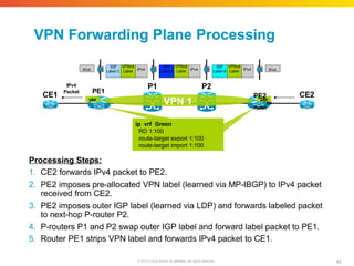
Processing P2 P1 CE1 CE2 ip vrf Green RD 1:100 route-target export 1:100 route-target import 1:100 Processing Steps: 1. CE2 forwards IPv4 packet to PE2. 2. PE2 imposes pre-allocated VPN label (learned via MP-IBGP) to IPv4 packet received from CE2. 3. PE2 imposes outer IGP label (learned via LDP) and forwards labeled packet to next-hop P-router P2. 4. P-routers P1 and P2 swap outer IGP label and forward label packet to PE1. 5. Router PE1 strips VPN label and forwards IPv4 packet to CE1. IPv4 Packet PE1 VRF VRF VPN 1 PE2 Packet I P v 4 IPv4 IGP Label A VPNv4 IPv4 Label IGP Label B VPNv4 IPv4 Label IGP Label C VPNv4 IPv4 Label IPv4 44 © 2010 Cisco and/or its affiliates. All rights reserved.
45.
Use Case 1:
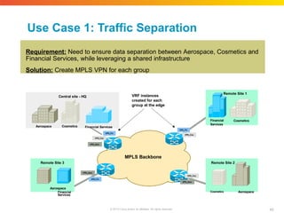
Traffic Separation Requirement: Need to ensure data separation between Aerospace, Cosmetics and Financial Services, while leveraging a shared infrastructure Solution: Create MPLS VPN for each group Aerospace Cosmetics Financial Services Central site - HQ Cosmetics Financial Services Remote Site 1 Remote Site 2 Cosmetics Aerospace Remote Site 3 Aerospace Financial Services VPN_Fin 45 © 2010 Cisco and/or its affiliates. All rights reserved. VPN_Fin VPN_Fin VPN_Cos VPN_Cos VPN_Cos VPN_Aero VPN_Aero VPN_Aero MPLS Backbone VRF instances created for each group at the edge
46.
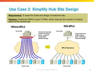
Use Case 2:
Simplify Hub Site Design Requirement: To ease the scale and design of head-end site Solution: Implement MPLS Layer 3 VPNs, which reduces the number of routing peers of the central site Central Site Remote Sites Central site has high number of routing peers – creates a complicated headend design Central Site Remote Sites Central site has a single routing peer – enhancing head-end design MPLS Backbone 46 © 2010 Cisco and/or its affiliates. All rights reserved.
47.
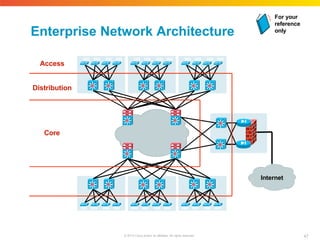
Enterprise Network Architecture Access Distribution Core Internet For
your reference only 47 © 2010 Cisco and/or its affiliates. All rights reserved.
48.
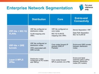
Enterprise Network Segmentation Distribution
Core End-to-end Connectivity VRF-lite + 802.1Q VLANs VRF lite configured on distribution nodes VLAN mapping onto VRFs VRF lite configured on core nodes 802.1Q VLAN ID mapping onto VRFs Device Separation: VRF Data Path Separation: 802.1Q VLAN ID VRF-lite + GRE tunnels VRF lite configured on distribution nodes VRFs associated with GRE tunnels Core nodes forward IP packets (GRE IP Packets) End-to-end GRE tunnels between distribution nodes Layer-3 MPLS VPNs Distribution nodes configured as PE routers with VRF(s) Core nodes forward MPLS packets (via LFIB) End-to-end label switched paths (LSPs) between distribution nodes (PE routers) For your reference only 48 © 2010 Cisco and/or its affiliates. All rights reserved.
49.
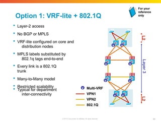
Option 1: VRF-lite
+ 802.1Q Layer-2 access No BGP or MPLS VRF-lite configured on core and distribution nodes MPLS labels substituted by 802.1q tags end-to-end Every link is a 802.1Q trunk Many-to-Many model Restricted scalability Typical for department inter-connectivity v v v v v Layer 3 L2 L2 v v v v Multi-VRF VPN1 VPN2 802.1Q For your reference only 49 © 2010 Cisco and/or its affiliates. All rights reserved.
50.
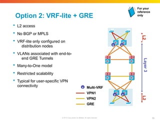
Option 2: VRF-lite
+ GRE L2 access No BGP or MPLS VRF-lite only configured on distribution nodes VLANs associated with end-to- end GRE Tunnels Many-to-One model Restricted scalability Typical for user-specific VPN connectivity v v v v v Layer 3 L2 L2 Multi-VRF VPN1 VPN2 GRE For your reference only 50 © 2010 Cisco and/or its affiliates. All rights reserved.
51.
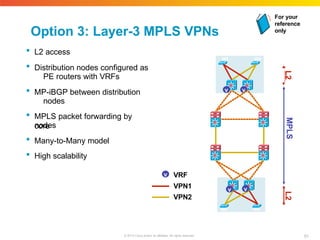
Option 3: Layer-3
MPLS VPNs L2 access Distribution nodes configured as PE routers with VRFs MP-iBGP between distribution nodes MPLS packet forwarding by core nodes Many-to-Many model High scalability v v v v v MPLS L2 L2 VRF VPN1 VPN2 For your reference only 51 © 2010 Cisco and/or its affiliates. All rights reserved.
52.
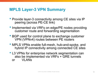
MPLS Layer-3 VPN
Summary 52 © 2010 Cisco and/or its affiliates. All rights reserved. Provide layer-3 connectivity among CE sites via IP peering (across PE-CE link) Implemented via VRFs on edge/PE nodes providing customer route and forwarding segmentation BGP used for control plane to exchange customer VPN (VPNv4) routes between PE routers MPLS VPNs enable full-mesh, hub-and-spoke, and hybrid IP connectivity among connected CE sites L3 VPNs for enterprise network segmentation can also be implemented via VRFs + GRE tunnels or VLANs
53.
Cisco Public Presentation_ID ©
2010 Cisco and/or its affiliates. All rights reserved. 53 MPLS Layer-2 VPNs Technology Overview and Applications
54.
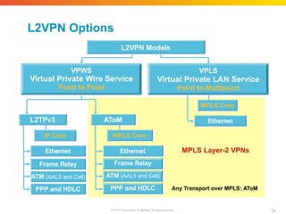
MPLS Layer-2 VPNs L2VPN
Options VPLS Virtual Private LAN Service Point to Multipoint VPWS Virtual Private Wire Service Point to Point L2VPN Models AToM L2TPv3 IP Core Frame Relay ATM (AAL5 and Cell) Ethernet PPP and HDLC MPLS Core Ethernet Frame Relay ATM (AAL5 and Cell) PPP and HDLC MPLS Core Ethernet Any Transport over MPLS: AToM 54 © 2010 Cisco and/or its affiliates. All rights reserved.
55.
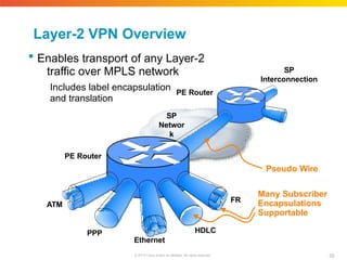
Layer-2 VPN Overview
Enables transport of any Layer-2 traffic over MPLS network Includes label encapsulation and translation Ethernet ATM HDLC PPP FR Pseudo Wire SP Networ k SP Interconnection PE Router PE Router 55 © 2010 Cisco and/or its affiliates. All rights reserved. Many Subscriber Encapsulations Supportable
56.
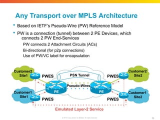
Any Transport over
MPLS Architecture Based on IETF’s Pseudo-Wire (PW) Reference Model PW is a connection (tunnel) between 2 PE Devices, which connects 2 PW End-Services PW connects 2 Attachment Circuits (ACs) Bi-directional (for p2p connections) Use of PW/VC label for encapsulation Pseudo-Wires Emulated Layer-2 Service PWES PWES PSN Tunnel PWES PWES Customer2 Site1 Customer1 Site1 Customer1 Site2 PE PE Customer2 Site2 56 © 2010 Cisco and/or its affiliates. All rights reserved.
57.
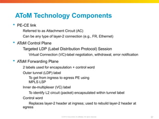
AToM Technology Components 57 ©
2010 Cisco and/or its affiliates. All rights reserved. PE-CE link Referred to as Attachment Circuit (AC) Can be any type of layer-2 connection (e.g., FR, Ethernet) AToM Control Plane Targeted LDP (Label Distribution Protocol) Session Virtual Connection (VC)-label negotiation, withdrawal, error notification AToM Forwarding Plane 2 labels used for encapsulation + control word Outer tunnel (LDP) label To get from ingress to egress PE using MPLS LSP Inner de-multiplexer (VC) label To identify L2 circuit (packet) encapsulated within tunnel label Control word Replaces layer-2 header at ingress; used to rebuild layer-2 header at egress
58.
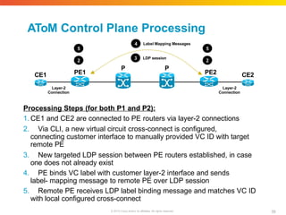
AToM Control Plane
Processing Processing Steps (for both P1 and P2): 1. CE1 and CE2 are connected to PE routers via layer-2 connections 2. Via CLI, a new virtual circuit cross-connect is configured, connecting customer interface to manually provided VC ID with target remote PE 3. New targeted LDP session between PE routers established, in case one does not already exist 4. PE binds VC label with customer layer-2 interface and sends label- mapping message to remote PE over LDP session 5. Remote PE receives LDP label binding message and matches VC ID with local configured cross-connect P P PE1 PE2 CE1 CE2 Layer-2 Connection Layer-2 Connection 3 LDP session 4 58 © 2010 Cisco and/or its affiliates. All rights reserved. Label Mapping Messages 2 2 5 5
59.
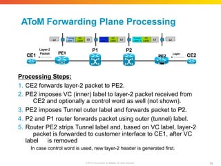
AToM Forwarding Plane
Processing Processing Steps: 1. CE2 forwards layer-2 packet to PE2. 2. PE2 imposes VC (inner) label to layer-2 packet received from CE2 and optionally a control word as well (not shown). 3. PE2 imposes Tunnel outer label and forwards packet to P2. 4. P2 and P1 router forwards packet using outer (tunnel) label. 5. Router PE2 strips Tunnel label and, based on VC label, layer-2 packet is forwarded to customer interface to CE1, after VC label is removed In case control word is used, new layer-2 header is generated first. P2 P1 CE1 CE2 Layer-2 Packet PE1 PE2 Layer- 2 P a c k e t L2 Tunnel Label A VC Label L2 Tunnel Label B VC Label L2 Tunnel Label C VC Label L2 L2 59 © 2010 Cisco and/or its affiliates. All rights reserved.
60.
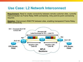
Use Case: L2
Network Interconnect Requirement: Need to create connectivity between remote customer sites, currently interconnected via Frame Relay WAN connectivity. Only point-to-point connectivity required. Solution: Interconnect AToM PW between sites, enabling transparent Frame Relay WAN connectivity. PE1 Backbone PE2 CPE Router, FRAD DLCI 101 DLCI 201 Directed LDP Label Exchange for VC1 – Label 10 60 © 2010 Cisco and/or its affiliates. All rights reserved. Neighbor LDP– Label 50 Neighbor LDP– Label 90 MPLS 101 10 50 101 10 90 VC1 – Connects DLCI 101 to DLCI 201 CPE Router, FRAD
61.
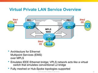
Virtual Private LAN
Service Overview PE1 PE2 MPLS WAN Site3 CE Architecture for Ethernet Multipoint Services (EMS) over MPLS Emulates IEEE Ethernet bridge; VPLS network acts like a virtual switch that emulates conventional L2 bridge Fully meshed or Hub-Spoke topologies supported Site2 CE Site1 CE 61 © 2010 Cisco and/or its affiliates. All rights reserved.
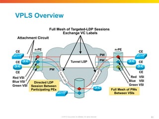
62.
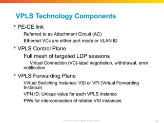
VPLS Technology Components 62 ©
2010 Cisco and/or its affiliates. All rights reserved. PE-CE link Referred to as Attachment Circuit (AC) Ethernet VCs are either port mode or VLAN ID VPLS Control Plane Full mesh of targeted LDP sessions Virtual Connection (VC)-label negotiation, withdrawal, error notification VPLS Forwarding Plane Virtual Switching Instance: VSI or VFI (Virtual Forwarding Instance) VPN ID: Unique value for each VPLS instance PWs for interconnection of related VSI instances
63.
VPLS Overview Directed LDP Session
Between Participating PEs n-PE n-PE PW PW PW CE CE CE CE Tunnel LSP CE Red VSI Blue VSI Green VSI CE Red VSI Blue VSI Green VSI Full Mesh of PWs Between VSIs Full Mesh of Targeted-LDP Sessions Exchange VC Labels Attachment Circuit 63 © 2010 Cisco and/or its affiliates. All rights reserved.
64.
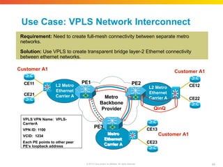
Use Case: VPLS
Network Interconnect Requirement: Need to create full-mesh connectivity between separate metro networks. Solution: Use VPLS to create transparent bridge layer-2 Ethernet connectivity between ethernet networks. Customer A1 Metro Ethernet Carrier A CE13 CE23 Metro Backbone Provider PE1 PE2 Customer A1 Customer A1 CE11 CE21 CE12 CE22 PE3 VPLS VPN Name: VPLS- CarrierA VPN ID: 1100 VCID: 1234 Each PE points to other peer PE’s loopback address QinQ 64 © 2010 Cisco and/or its affiliates. All rights reserved.
65.
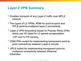
Layer-2 VPN Summary 65 ©
2010 Cisco and/or its affiliates. All rights reserved. Enables transport of any Layer-2 traffic over MPLS network Two types of L2 VPNs; AToM for point-to-point and VPLS point-to-multipoint layer-2 connectivity Layer-2 VPN forwarding based on Pseudo Wires (PW), which use VC label for L2 packet encapsulation LDP used for PW signaling AToM PWs suited for implementing transparent point-to- point connectivity between Layer-2 circuits VPLS suited for implementing transparent point-to- multipoint connectivity between Ethernet links/sites
66.
Cisco Public Presentation_ID ©
2010 Cisco and/or its affiliates. All rights reserved. 66 MPLS QoS Technology Overview and Applications
67.
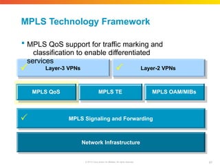
MPLS Technology Framework Network
Infrastructure MPLS Signaling and Forwarding Layer-3 VPNs Layer-2 VPNs MPLS QoS MPLS TE MPLS OAM/MIBs 67 © 2010 Cisco and/or its affiliates. All rights reserved. MPLS QoS support for traffic marking and classification to enable differentiated services
68.
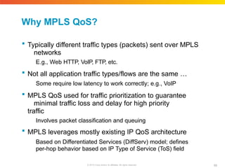
Why MPLS QoS? 68 ©
2010 Cisco and/or its affiliates. All rights reserved. Typically different traffic types (packets) sent over MPLS networks E.g., Web HTTP, VoIP, FTP, etc. Not all application traffic types/flows are the same … Some require low latency to work correctly; e.g., VoIP MPLS QoS used for traffic prioritization to guarantee minimal traffic loss and delay for high priority traffic Involves packet classification and queuing MPLS leverages mostly existing IP QoS architecture Based on Differentiated Services (DiffServ) model; defines per-hop behavior based on IP Type of Service (ToS) field
69.
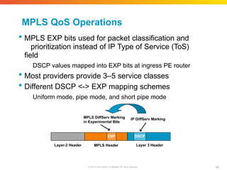
MPLS QoS Operations
MPLS EXP bits used for packet classification and prioritization instead of IP Type of Service (ToS) field DSCP values mapped into EXP bits at ingress PE router Most providers provide 3–5 service classes Different DSCP <-> EXP mapping schemes Uniform mode, pipe mode, and short pipe mode MPLS Header Layer-2 Header Layer 3 Header MPLS DiffServ Marking in Experimental Bits IP DiffServ Marking EXP DSCP 69 © 2010 Cisco and/or its affiliates. All rights reserved.
70.
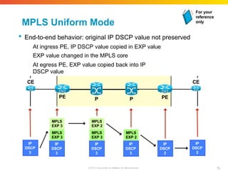
MPLS Uniform Mode
End-to-end behavior: original IP DSCP value not preserved At ingress PE, IP DSCP value copied in EXP value EXP value changed in the MPLS core At egress PE, EXP value copied back into IP DSCP value P P PE PE CE CE IP DSCP 3 IP DSCP 3 MPLS EXP 3 MPLS EXP 3 IP DSCP 2 IP DSCP 3 MPLS EXP 3 MPLS EXP 2 IP DSCP 3 MPLS EXP 2 IP DSCP 2 For your reference only 70 © 2010 Cisco and/or its affiliates. All rights reserved.
71.
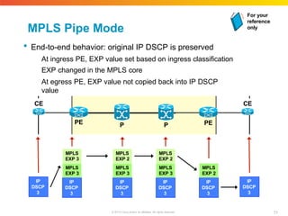
MPLS Pipe Mode
End-to-end behavior: original IP DSCP is preserved At ingress PE, EXP value set based on ingress classification EXP changed in the MPLS core At egress PE, EXP value not copied back into IP DSCP value P P PE PE CE CE IP DSCP 3 IP DSCP 3 MPLS EXP 3 MPLS EXP 3 IP DSCP 3 IP DSCP 3 MPLS EXP 3 MPLS EXP 2 IP DSCP 3 MPLS EXP 2 IP DSCP 3 MPLS EXP 3 MPLS EXP 2 For your reference only 71 © 2010 Cisco and/or its affiliates. All rights reserved.
72.
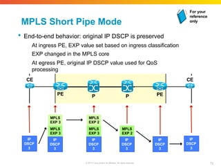
MPLS Short Pipe
Mode End-to-end behavior: original IP DSCP is preserved At ingress PE, EXP value set based on ingress classification EXP changed in the MPLS core At egress PE, original IP DSCP value used for QoS processing P P PE PE CE CE IP DSCP 3 IP DSCP 3 MPLS EXP 3 MPLS EXP 3 IP DSCP 3 IP DSCP 3 MPLS EXP 3 MPLS EXP 2 IP DSCP 3 MPLS EXP 2 IP DSCP 3 For your reference only 72 © 2010 Cisco and/or its affiliates. All rights reserved.
73.
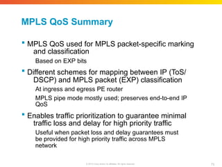
MPLS QoS Summary 73 ©
2010 Cisco and/or its affiliates. All rights reserved. MPLS QoS used for MPLS packet-specific marking and classification Based on EXP bits Different schemes for mapping between IP (ToS/ DSCP) and MPLS packet (EXP) classification At ingress and egress PE router MPLS pipe mode mostly used; preserves end-to-end IP QoS Enables traffic prioritization to guarantee minimal traffic loss and delay for high priority traffic Useful when packet loss and delay guarantees must be provided for high priority traffic across MPLS network
74.
Cisco Public Presentation_ID ©
2010 Cisco and/or its affiliates. All rights reserved. 74 MPLS Traffic Engineering Technology Overview and Applications
75.
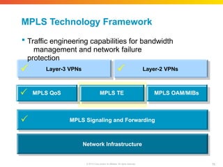
MPLS Technology Framework Network
Infrastructure MPLS Signaling and Forwarding Layer-3 VPNs Layer-2 VPNs MPLS QoS MPLS TE MPLS OAM/MIBs 75 © 2010 Cisco and/or its affiliates. All rights reserved. Traffic engineering capabilities for bandwidth management and network failure protection
76.
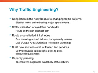
Why Traffic Engineering? 76 ©
2010 Cisco and/or its affiliates. All rights reserved. Congestion in the network due to changing traffic patterns Election news, online trading, major sports events Better utilization of available bandwidth Route on the non-shortest path Route around failed links/nodes Fast rerouting around failures, transparently to users Like SONET APS (Automatic Protection Switching) Build new services—virtual leased line services VoIP toll-bypass applications, point-to-point bandwidth guarantees Capacity planning TE improves aggregate availability of the network
77.
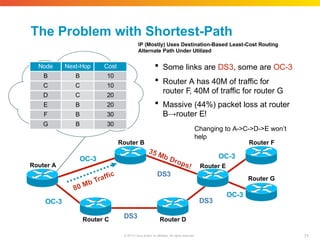
Router F 77 © 2010
Cisco and/or its affiliates. All rights reserved. Router C Router D Router A Router B OC-3 OC-3 DS3 DS3 DS3 OC-3 Some links are DS3, some are OC-3 Router A has 40M of traffic for router F, 40M of traffic for router G Massive (44%) packet loss at router B→router E! Changing to A->C->D->E won’t help OC-3 Router E Router G Node Next-Hop Cost B B 10 C C 10 D C 20 E B 20 F B 30 G B 30 The Problem with Shortest-Path IP (Mostly) Uses Destination-Based Least-Cost Routing Alternate Path Under Utilized
78.
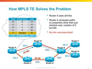
How MPLS TE
Solves the Problem Router A sees all links Router A computes paths on properties other than just shortest cost; creation of 2 tunnels No link oversubscribed! 78 © 2010 Cisco and/or its affiliates. All rights reserved. OC-3 OC-3 DS3 DS3 DS3 OC-3 Router F Router C Router D Router G Router A Router B OC-3 Router E 40 Mb Node Next-Hop Cost B B 10 C C 10 D C 20 E B 20 F Tunnel 0 30 G Tunnel 1 30
79.
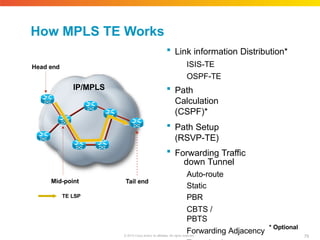
How MPLS TE
Works Link information Distribution* ISIS-TE OSPF-TE Path Calculation (CSPF)* Path Setup (RSVP-TE) Forwarding Traffic down Tunnel Auto-route Static PBR CBTS / PBTS Forwarding Adjacency * Optional IP/MPLS Head end Mid-point Tail end TE LSP 79 © 2010 Cisco and/or its affiliates. All rights reserved.
80.
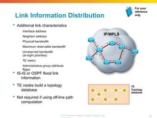
Link Information Distribution
Additional link characteristics Interface address Neighbor address Physical bandwidth Maximum reservable bandwidth Unreserved bandwidth (at eight priorities) TE metric Administrative group (attribute flags) IS-IS or OSPF flood link information TE nodes build a topology database Not required if using off-line path computation IP/MPLS TE Topology database For your reference only 80 © 2010 Cisco and/or its affiliates. All rhigtthpts://rweswewrv.ecdis.
81.
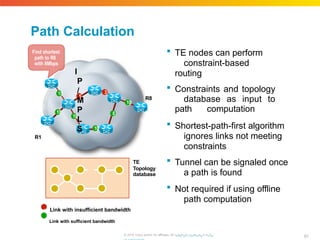
Path Calculation TE
nodes can perform constraint-based routing Constraints and topology database as input to path computation Shortest-path-first algorithm ignores links not meeting constraints Tunnel can be signaled once a path is found Not required if using offline path computation TE Topology database 5 3 10 15 10 10 8 10 R8 Find shortest path to R8 with 8Mbps I P / M P L S R1 n Link with insufficient bandwidth n Link with sufficient bandwidth 81 © 2010 Cisco and/or its affiliates. All rhigtthpts://rweswewrv.ecdis.
82.
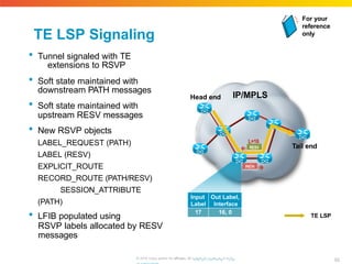
TE LSP Signaling
Tunnel signaled with TE extensions to RSVP Soft state maintained with downstream PATH messages Soft state maintained with upstream RESV messages New RSVP objects LABEL_REQUEST (PATH) LABEL (RESV) EXPLICIT_ROUTE RECORD_ROUTE (PATH/RESV) SESSION_ATTRIBUTE (PATH) LFIB populated using RSVP labels allocated by RESV messages IP/MPLS Head end Tail end TE LSP PATH RESV L=16 Input Out Label, Label Interface 17 16, 0 For your reference only 82 © 2010 Cisco and/or its affiliates. All rhigtthpts://rweswewrv.ecdis.
83.
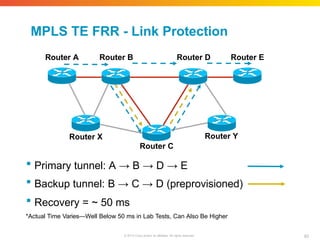
MPLS TE FRR
- Link Protection Router A Router B Router D Router E Router Y Router X Router C Primary tunnel: A → B → D → E Backup tunnel: B → C → D (preprovisioned) Recovery = ~ 50 ms *Actual Time Varies—Well Below 50 ms in Lab Tests, Can Also Be Higher 83 © 2010 Cisco and/or its affiliates. All rights reserved.
84.
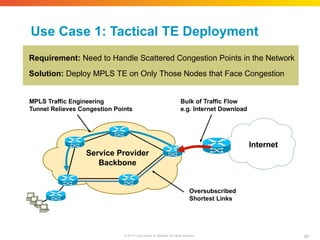
Use Case 1:
Tactical TE Deployment Requirement: Need to Handle Scattered Congestion Points in the Network Solution: Deploy MPLS TE on Only Those Nodes that Face Congestion Internet Service Provider Backbone Bulk of Traffic Flow e.g. Internet Download 84 © 2010 Cisco and/or its affiliates. All rights reserved. Oversubscribed Shortest Links MPLS Traffic Engineering Tunnel Relieves Congestion Points
85.
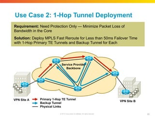
Use Case 2:
1-Hop Tunnel Deployment Requirement: Need Protection Only — Minimize Packet Loss of Bandwidth in the Core Solution: Deploy MPLS Fast Reroute for Less than 50ms Failover Time with 1-Hop Primary TE Tunnels and Backup Tunnel for Each Service Provider Backbone VPN Site A VPN Site B Primary 1-Hop TE Tunnel Backup Tunnel Physical Links 85 © 2010 Cisco and/or its affiliates. All rights reserved.
86.
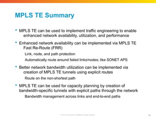
MPLS TE Summary 86 ©
2010 Cisco and/or its affiliates. All rights reserved. MPLS TE can be used to implement traffic engineering to enable enhanced network availability, utilization, and performance Enhanced network availability can be implemented via MPLS TE Fast Re-Route (FRR) Link, node, and path protection Automatically route around failed links/nodes; like SONET APS Better network bandwidth utilization can be implemented via creation of MPLS TE tunnels using explicit routes Route on the non-shortest path MPLS TE can be used for capacity planning by creation of bandwidth-specific tunnels with explicit paths through the network Bandwidth management across links and end-to-end paths
87.
Cisco Public Presentation_ID ©
2010 Cisco and/or its affiliates. All rights reserved. 87 MPLS Management Technology Overview and Applications
88.
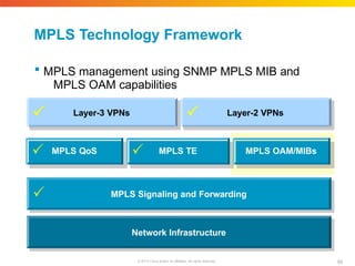
MPLS Technology Framework Network
Infrastructure MPLS Signaling and Forwarding Layer-3 VPNs Layer-2 VPNs MPLS QoS MPLS TE MPLS OAM/MIBs 88 © 2010 Cisco and/or its affiliates. All rights reserved. MPLS management using SNMP MPLS MIB and MPLS OAM capabilities
89.
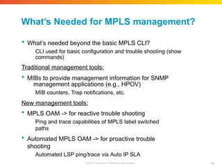
What’s Needed for
MPLS management? 89 © 2010 Cisco and/or its affiliates. All rights reserved. What’s needed beyond the basic MPLS CLI? CLI used for basic configuration and trouble shooting (show commands) Traditional management tools: MIBs to provide management information for SNMP management applications (e.g., HPOV) MIB counters, Trap notifications, etc. New management tools: MPLS OAM -> for reactive trouble shooting Ping and trace capabilities of MPLS label switched paths Automated MPLS OAM -> for proactive trouble shooting Automated LSP ping/trace via Auto IP SLA
90.
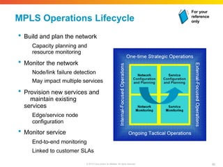
MPLS Operations Lifecycle
Build and plan the network Capacity planning and resource monitoring Monitor the network Node/link failure detection May impact multiple services Provision new services and maintain existing services Edge/service node configuration Monitor service End-to-end monitoring Linked to customer SLAs For your reference only 90 © 2010 Cisco and/or its affiliates. All rights reserved.
91.
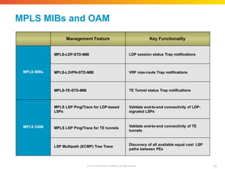
MPLS MIBs and
OAM Management Feature Key Functionality MPLS MIBs MPLS-LDP-STD-MIB LDP session status Trap notifications MPLS-L3VPN-STD-MIB VRF max-route Trap notifications MPLS-TE-STD-MIB TE Tunnel status Trap notifications MPLS OAM MPLS LSP Ping/Trace for LDP-based LSPs Validate end-to-end connectivity of LDP- signaled LSPs MPLS LSP Ping/Trace for TE tunnels Validate end-to-end connectivity of TE tunnels LSP Multipath (ECMP) Tree Trace Discovery of all available equal cost LSP paths between PEs 91 © 2010 Cisco and/or its affiliates. All rights reserved.
92.
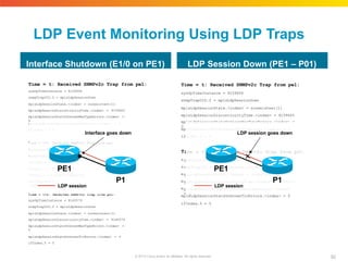
LDP Event Monitoring
Using LDP Traps Time = t: Received SNMPv2c Trap from pe1: sysUpTimeInstance = 8159606 snmpTrapOID.0 = mplsLdpSessionDown mplsLdpSessionState.<index> = nonexistent(1) mplsLdpSessionDiscontinuityTime.<index> = 8159605 mplsLdpSessionStatsUnknownMesTypeErrors.<index> = 0 m i T s s i i i l plsLdpSessionStatsUnknownTlvErrors.<index> = 0 fIndex.5 = 5 ime = t+1: Received SNMPv2c Trap from pe1: ysUpTimeInstance = 8159906 nmpTrapOID.0 = linkDown fIndex.5 = 5 fDescr.5 = Ethernet1/0 fType.5 = ethernetCsmacd(6) ocIfReason.5 = administratively down Time = t+2: Received SNMPv2c Trap from p01: sysUpTimeInstance = 8160579 snmpTrapOID.0 = mplsLdpSessionDown mplsLdpSessionState.<index> = nonexistent(1) mplsLdpSessionDiscontinuityTime.<index> = 8160579 mplsLdpSessionStatsUnknownMesTypeErrors.<index> = 0 mplsLdpSessionStatsUnknownTlvErrors.<index> = 0 ifIndex.5 = 5 Time = t: Received SNMPv2c Trap from pe1: sysUpTimeInstance = 8159606 snmpTrapOID.0 = mplsLdpSessionDown mplsLdpSessionState.<index> = nonexistent(1) mplsLdpSessionDiscontinuityTime.<index> = 8159605 mplsLdpSessionStatsUnknownMesTypeErrors.<index> = 0 m i T s s m m m plsLdpSessionStatsUnknownTlvErrors.<index> = 0 fIndex.5 = 5 ime = t+1: Received SNMPv2c Trap from p01: ysUpTimeInstance = 8160579 nmpTrapOID.0 = mplsLdpSessionDown plsLdpSessionState.<index> = nonexistent(1) plsLdpSessionDiscontinuityTime.<index> = 8160579 plsLdpSessionStatsUnknownMesTypeErrors.<index> = 0 mplsLdpSessionStatsUnknownTlvErrors.<index> = 0 ifIndex.5 = 5 Interface Shutdown (E1/0 on PE1) LDP Session Down (PE1 – P01) PE1 P1 LDP session Interface goes down PE1 P1 LDP session LDP session goes down 92 © 2010 Cisco and/or its affiliates. All rights reserved.
93.
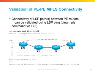
Validation of PE-PE
MPLS Connectivity Connectivity of LSP path(s) between PE routers can be validated using LSP ping (ping mpls command via CLI) pe1>ping mpls ipv4 10.1.2.249/32 Sending 5, 100-byte MPLS Echos to 10.1.2.249/32, Code 'L' 'D' 'M' 'P' 'R' 'X' timeout is 2 seconds, send interval is 0 msec: s: '!' - success, 'Q' - request not sent, '.' - timeout, - labeled output interface, 'B' - unlabeled output interface, - DS Map mismatch, 'F' - no FEC mapping, 'f' - FEC mismatch, - malformed request, 'm' - unsupported tlvs, 'N' - no label entry, - no rx intf label prot, 'p' - premature termination of LSP, - transit router, 'I' - unknown upstream index, - unknown return code, 'x' - return code 0 Type escape sequence to abort. !!!!! Success rate is 100 percent (5/5), round-trip min/avg/max = 284/294/300 ms PE1 P1 93 © 2010 Cisco and/or its affiliates. All rights reserved. P2 PE2
94.
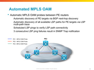
Automated MPLS OAM
Automatic MPLS OAM probes between PE routers Automatic discovery of PE targets via BGP next-hop discovery Automatic discovery of all available LSP paths for PE targets via LSP multi-path trace Scheduled LSP pings to verify LSP path connectivity 3 consecutive LSP ping failures result in SNMP Trap notification PE3 PE2 P2 P1 PE1 PE1 - MPLS OAM Probe PE2 - MPLS OAM Probe PE3 - MPLS OAM Probe 94 © 2010 Cisco and/or its affiliates. All rights reserved.
95.
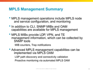
MPLS Management Summary 95 ©
2010 Cisco and/or its affiliates. All rights reserved. MPLS management operations include MPLS node and service configuration, and monitoring In addition to CLI, SNMP MIBs and OAM capabilities are available for MPLS management MPLS MIBs provide LDP, VPN, and TE management information, which can be collected by SNMP tools MIB counters, Trap notifications Advanced MPLS management capabilities can be implemented via MPLS OAM LSP path discovery and connectivity validation Proactive monitoring via automated MPLS OAM
96.
Cisco Public Presentation_ID ©
2010 Cisco and/or its affiliates. All rights reserved. 96 Summary Final Notes and Wrap Up
97.
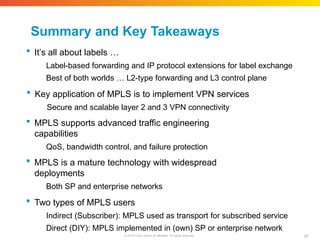
Summary and Key
Takeaways 97 © 2010 Cisco and/or its affiliates. All rights reserved. It’s all about labels … Label-based forwarding and IP protocol extensions for label exchange Best of both worlds … L2-type forwarding and L3 control plane Key application of MPLS is to implement VPN services Secure and scalable layer 2 and 3 VPN connectivity MPLS supports advanced traffic engineering capabilities QoS, bandwidth control, and failure protection MPLS is a mature technology with widespread deployments Both SP and enterprise networks Two types of MPLS users Indirect (Subscriber): MPLS used as transport for subscribed service Direct (DIY): MPLS implemented in (own) SP or enterprise network
98.
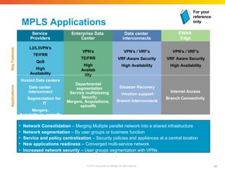
MPLS Applications EWAN Edge Service Providers Enterprise Data Center Data
center interconnects L2/L3VPN’s TE/FRR QoS High Availability VPN’s / VRF’s VRF-Aware Security High Availability Hosted Data centers Data center interconnect Segmentation for IT Mergers, Acquisitions, spinoffs Applications Key Features Departmental segmentation Service multiplexing Security Mergers, Acquisitions, spinoffs Disaster Recovery Vmotion support Branch Interconnects Internet Access Branch Connectivity VPN’s / VRF’s VRF Aware Security High Availability VPN’s TE/FRR High Availab ility • Network Consolidation – Merging Multiple parallel network into a shared infrastructure • Network segmentation – By user groups or business function • Service and policy centralization – Security policies and appliances at a central location • New applications readiness – Converged multi-service network • Increased network security – User groups segmentation with VPNs For your reference only 98 © 2010 Cisco and/or its affiliates. All rights reserved.
99.
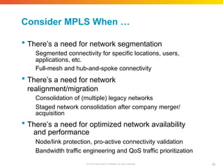
Consider MPLS When
… 99 © 2010 Cisco and/or its affiliates. All rights reserved. There’s a need for network segmentation Segmented connectivity for specific locations, users, applications, etc. Full-mesh and hub-and-spoke connectivity There’s a need for network realignment/migration Consolidation of (multiple) legacy networks Staged network consolidation after company merger/ acquisition There’s a need for optimized network availability and performance Node/link protection, pro-active connectivity validation Bandwidth traffic engineering and QoS traffic prioritization
100.
Cisco Public Presentation_ID ©
2010 Cisco and/or its affiliates. All rights reserved. 100 Q and A
101.
© 2010 Cisco
and/or its affiliates. All rights reserved. 101
Download