The document discusses the mechanics and advantages of MPLS VPNs, which utilize Multiprotocol Label Switching (MPLS) and Border Gateway Protocol (BGP) to enhance packet forwarding and create secure, cost-effective virtual private networks for enterprises. It outlines the architecture of MPLS, including the roles of label edge routers and label switch routers, and distinguishes MPLS VPNs from traditional WAN solutions. Furthermore, it elucidates various VPN models and implementations, highlighting the efficiency and scalability of MPLS-based services compared to older connection methods.

![a. Implementation
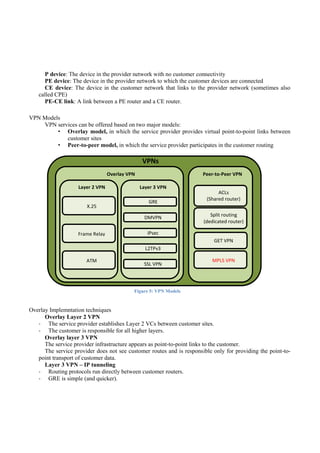
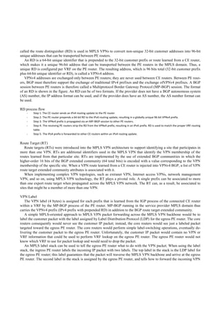
MPLS Architecture
In the MPLS VPN architecture, the edge routers carry customer routing information, providing optimal routing for
traffic that belongs to the customer for inter-site traffic. The MPLS-based VPN model also accommodates customers
who use overlapping address spaces, unlike the traditional peer-to-peer model, in which optimal routing of customer
traffic required the provider to assign IP addresses to each of its customers (or the customer to implement Network Ad-
dress Translation [NAT]) to avoid overlapping address spaces.
MPLS VPN is an implementation of the peer-to-peer model; the MPLS VPN backbone and customer sites exchange
Layer 3 customer routing information, and data is forwarded between customer sites using the MPLS-enabled service
provider IP backbone.
The MPLS VPN domain, like the traditional VPN, consists of the customer network and the provider network. The
MPLS VPN model is very similar to the dedicated provider edge (PE) router model in a peer-to-peer VPN implementa-
tion. However, instead of deploying a dedicated PE router per customer, customer traffic is isolated on the same PE rout-
er that provides connectivity into the service provider network for multiple customers.
In the MPLS VPN implementation, the PE router performs multiple functions. The PE router must first be capable of
isolating customer traffic if more than one customer is connected to the PE router. Each customer, therefore, is assigned
an independent routing table (virtual routing table or virtual routing and forwarding [VRF] table) similar to a dedicated
PE router in the initial peer-to-peer discussion. Routing across the service provider backbone is performed using a rout-
ing process in the global routing table. P routers provide label switching between PE routers and are unaware of VPN
routes. CE routers in the customer network are not aware of the P routers, and thus the internal topology of the service
provider network is transparent to the customer. And to enable scaling the networkto a large number of customer VPNs,
Multiprotocol Border Gateway Protocol (MP-BGP) isconfigured between PE routers to carry customer routes.
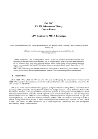
Figure 6: Simple VPN Architecture
The P routers are responsible only for label switching of packets. They do not carry VPN routes and do not participate
in MPLS VPN routing. The PE routers exchange IPv4 routes with connected CE routers using individual routing proto-
col contexts. To enable scaling the network to a large number of customer VPNs, Multiprotocol Border Gateway Proto-
col (MP-BGP) is configured between PE routers to carry customer routes.](https://image.slidesharecdn.com/report-180406165933/85/VPN-Using-MPLS-Technique-9-320.jpg)
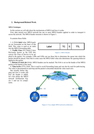
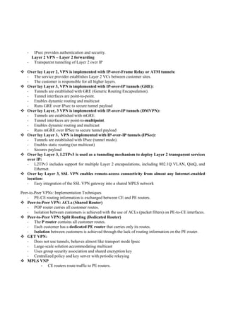
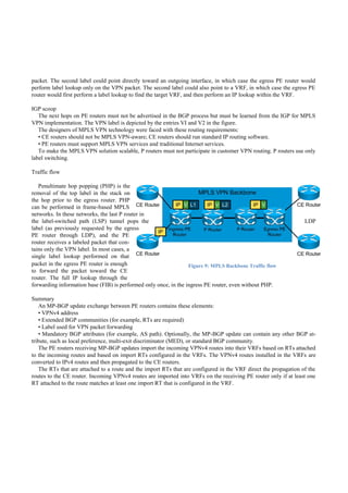
![Virtual Routing and Forwarding tables (VRFs)
The global routing table (or forwarding in case of
Layer 2 switching) is not the same as the VRF as the
global interface includes only the IPV4 or IPV6 infor-
mation (or MAC addresses per interface in case of
Layer 2 switching) and only one global
routing table can exist in a single router.
The VRFs instead can contain more infor-
mation as explained next and more than one
VRF can coexist in the same router.
The VRF contains an IP routing table that is analo- gous to the global IP
routing table, a Cisco Express Forwarding
table, a list of interfaces that are part of the
VRF, and a set of rules defining routing
protocol exchange with attached CE routers (routing protocol contexts). In addition, the VRF also contains VPN identifi-
ers and VPN membership information (route distinguisher [RD] and route target [RT] are covered in the next section).
The interface that is part of the VRF must support Cisco Express Forwarding switching. The number of interfaces that
can be bound to a VRF is limited only by the number of interfaces on the router, and a single interface (logical or physi-
cal) can be associated with only one VRF.
In the MPLS VPN routing model, the PE router provides isolation between customers using VRFs. However, this in-
formation must be carried between PE routers to enable data transfer between customer sites via the MPLS VPN back-
bone. The PE router must be capable of implementing processes that enable overlapping address spaces in connected
customer networks.
The PE router must also learn these routes from attached customer networks and propagate this information using the
shared provider backbone. This is done by the association of an RD per virtual routing table on a PE router.
MP-BGPV4
The next design decision to be made is the choice of the routing protocol running between PE routers. Given that the
total number of customer routes is expected to be very large, the only well-known protocol with the required scalability
is Border Gateway Protocol version 4 (BGP4). In fact, BGP4 is used in the MPLS VPN architecture to transport custom-
er routes directly between PE routers. MPLS VPN architecture differs in an important way from traditional peer-to-peer
VPN solutions: MPLS VPNs support overlapping customer address spaces.
MP-BGP is also responsible for the assignment of a VPN label. Packet forwarding in an MPLS VPN mandates that
the router specified as the next hop in the incoming BGP update is the same router that assigns the VPN label. An MP-
BGP session between PE routers in a single BGP AS is called a Multiprotocol Internal Border Gateway Protocol (MP-
IBGP) session and follows rules as in the implementation of IBGP with regards to BGP attributes. If the VPN extends
beyond a single AS, VPNv4 routes will be exchanged between autonomous systems at the AS boundaries using a Multi-
protocol External Border Gateway Protocol (MP-EBGP) session.
Route Distinguisher
With the deployment of a single routing protocol (that is, BGP4) exchang-
ing all customer routes between PE routers, an important issue arises: how
can BGP4 propagate several identical prefixes, belonging to different cus-
tomers, between PE routers? The only solution to this dilemma is the expan-
sion of customer IP prefixes with a unique prefix that makes them
unique even if they had previously overlapped. A 64- bit prefix
Figure 7: Explaining VRFs
Figure 8: RD Header](https://image.slidesharecdn.com/report-180406165933/85/VPN-Using-MPLS-Technique-10-320.jpg)
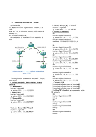
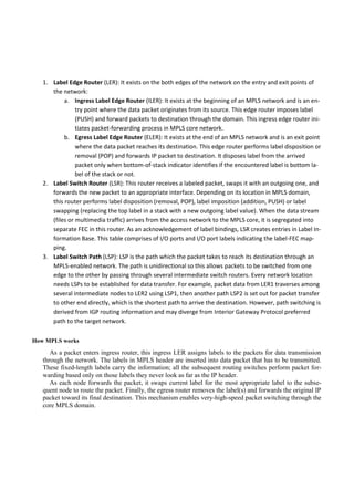
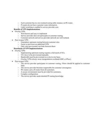
![4. Conclusions
The most scalable method of exchanging customer routes across a provider network is the use of an MP-BGP
between PE routers.
RDs transform non-unique 32-bit addresses into 96-bit unique addresses.
RTs are used to identify VPN membership in overlapping topologies.
• In MPLS VPNs:
CE routers run standard routing protocols to the PE routers.
PE routers provide the VPN routing and services via MP-BGP.
P routers do not participate in VPN routing, and only provide core IGP backbone routing to the PE routers.
• PE routers forward packets across the MPLS VPN backbone using label
5. Future Work
a. VPNv6 on the MPLS:
In this overview we only used the IPv4 of the traffic data, the implementation of IPv6 on the same way
can be more challenging
b. Layer 2 MPLS VPN:
We worked only on the Layer 3 MPLS VPN, and we look forward to see the results on the Layer 2
MPLS VPN.
c. Other vendors VPN MPLS:
At the start Cisco Studying material were available, so we only worked on the environment that is suit-
able for Cisco, also other vendors can be tricky to find academic material for, we are keen to see the
differences of other vendors in concept and implementation.
d. Security point of view:
We didn’t study the subject from the security perspective, so it would be a great benefit to study it se-
curity-wise.
6. References
[1] Cicso SPNGN1, SPNGN2, SPCORE material
[2] MPLS Enabled applications, Third edition.
[3] MPLS Virtual Private Networks, Luca Cittadini, Giuseppe Di Battista, Maurizio Patrignani..
[4] Implementation of MPLS L3VPN using GNS3, Akashy, Pooja Ahlawat](https://image.slidesharecdn.com/report-180406165933/85/VPN-Using-MPLS-Technique-15-320.jpg)