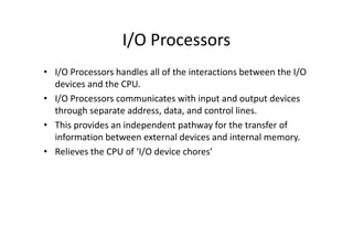
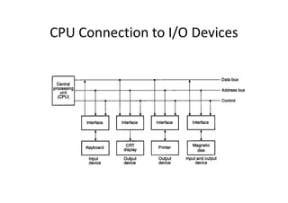
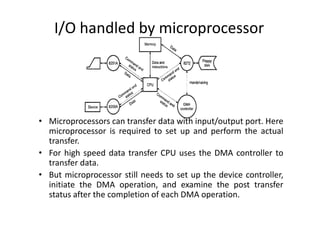
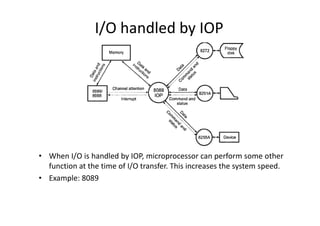
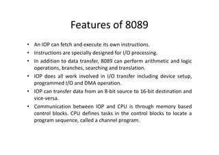
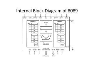
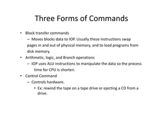
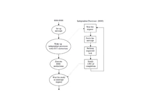
I/O Processor-8089
I/O Processors
• I/O Processors handles all of the interactions between the I/O
devices and the CPU.
• I/O Processors communicates with input and output devices
through separate address, data, and control lines.
• This provides an independent pathway for the transfer of
information between external devices and internal memory.
• Relieves the CPU of ‘I/O device chores’
CPU Connection to I/O Devices
I/O Processors
• Communicate directly with all I/O devices
– Fetch and execute its own instruction
• IOP instructions are specifically designed to facilitate I/O
transfer
• DMAC must be set up entirely by the CPU
– Designed to handle the details of I/O processing
• Used to address the problem of direct transfer after executing the
necessary format conversion or other instructions
• In an IOP-based system, I/O devices can directly access the memory
without intervention by the processor
I/O handled by microprocessor
• Microprocessors can transfer data with input/output port. Here
microprocessor is required to set up and perform the actual
transfer.
• For high speed data transfer CPU uses the DMA controller to
transfer data.
• But microprocessor still needs to set up the device controller,
initiate the DMA operation, and examine the post transfer
status after the completion of each DMA operation.
I/O handled by IOP
• When I/O is handled by IOP, microprocessor can perform some other
function at the time of I/O transfer. This increases the system speed.
• Example: 8089
Features of 8089
• An IOP can fetch and execute its own instructions.
• Instructions are specially designed for I/O processing.
• In addition to data transfer, 8089 can perform arithmetic and logic
operations, branches, searching and translation.
• IOP does all work involved in I/O transfer including device setup,
programmed I/O and DMA operation.
• IOP can transfer data from an 8-bit source to 16-bit destination and
vice-versa.
• Communication between IOP and CPU is through memory based
control blocks. CPU defines tasks in the control blocks to locate a
program sequence, called a channel program.
Internal Block Diagram of 8089
Pin Diagram
Registers of 8089
• GA- Points to source
• GB- Points to destination
• GC-Used as base address of a 256 byte translation table.
• TP-Task pointer
• PP-Parameter pointer
• IX –Index register
• BC
• MC- contains the it pattern to be compared and a mask in
bits 15 through 8
• CC-channel control
• PSW-Program status register
Channel control register
• Function control- b15 & b14
• Translation mode- b13
• Synchronization control-b12 & b11
• Source/ Destination indicator – b10
• Lock control- b9
• Lock control- b9
• Chaining control- b8
• Single transfer mode – b7
• Termination control – b0-b6
IOP Communication area
• SCPB(System Configuration pointer block)
– It contains three words:
– LS Byte specifies the width of system bus.
– Two words store the offset and segment address of the location
of the SCB.
• SCB
• SCB
– Offset and segment address of the beginning of two consecutive
channel control blocks in the system space.
• CBs
– CCW(channel Control word)
– Busy(FF/00)
– Parameter block’s offset and segment address.
Three Forms of Commands
• Block transfer commands
– Moves blocks data to IOP. Usually these instructions swap
pages in and out of physical memory, and to load programs from
disk memory.
• Arithmetic, logic, and Branch operations
– IOP uses ALU instructions to manipulate the data so the process
time for CPU is shorten.
• Control Command
– Controls hardware.
• Ex: rewind the tape on a tape drive or ejecting a CD from a
drive.
8089 microprocessor with diagram and analytical

8089 microprocessor with diagram and analytical

  • 1.
  • 2.
    I/O Processors • I/OProcessors handles all of the interactions between the I/O devices and the CPU. • I/O Processors communicates with input and output devices through separate address, data, and control lines. • This provides an independent pathway for the transfer of • This provides an independent pathway for the transfer of information between external devices and internal memory. • Relieves the CPU of ‘I/O device chores’
  • 3.
    CPU Connection toI/O Devices
  • 4.
    I/O Processors • Communicatedirectly with all I/O devices – Fetch and execute its own instruction • IOP instructions are specifically designed to facilitate I/O transfer • DMAC must be set up entirely by the CPU • DMAC must be set up entirely by the CPU – Designed to handle the details of I/O processing • Used to address the problem of direct transfer after executing the necessary format conversion or other instructions • In an IOP-based system, I/O devices can directly access the memory without intervention by the processor
  • 5.
    I/O handled bymicroprocessor • Microprocessors can transfer data with input/output port. Here microprocessor is required to set up and perform the actual transfer. • For high speed data transfer CPU uses the DMA controller to transfer data. • But microprocessor still needs to set up the device controller, initiate the DMA operation, and examine the post transfer status after the completion of each DMA operation.
  • 6.
    I/O handled byIOP • When I/O is handled by IOP, microprocessor can perform some other function at the time of I/O transfer. This increases the system speed. • Example: 8089
  • 7.
    Features of 8089 •An IOP can fetch and execute its own instructions. • Instructions are specially designed for I/O processing. • In addition to data transfer, 8089 can perform arithmetic and logic operations, branches, searching and translation. • IOP does all work involved in I/O transfer including device setup, • IOP does all work involved in I/O transfer including device setup, programmed I/O and DMA operation. • IOP can transfer data from an 8-bit source to 16-bit destination and vice-versa. • Communication between IOP and CPU is through memory based control blocks. CPU defines tasks in the control blocks to locate a program sequence, called a channel program.
  • 8.
  • 9.
  • 10.
    Registers of 8089 •GA- Points to source • GB- Points to destination • GC-Used as base address of a 256 byte translation table. • TP-Task pointer • PP-Parameter pointer • PP-Parameter pointer • IX –Index register • BC • MC- contains the it pattern to be compared and a mask in bits 15 through 8 • CC-channel control • PSW-Program status register
  • 11.
    Channel control register •Function control- b15 & b14 • Translation mode- b13 • Synchronization control-b12 & b11 • Source/ Destination indicator – b10 • Lock control- b9 • Lock control- b9 • Chaining control- b8 • Single transfer mode – b7 • Termination control – b0-b6
  • 12.
    IOP Communication area •SCPB(System Configuration pointer block) – It contains three words: – LS Byte specifies the width of system bus. – Two words store the offset and segment address of the location of the SCB. • SCB • SCB – Offset and segment address of the beginning of two consecutive channel control blocks in the system space. • CBs – CCW(channel Control word) – Busy(FF/00) – Parameter block’s offset and segment address.
  • 13.
    Three Forms ofCommands • Block transfer commands – Moves blocks data to IOP. Usually these instructions swap pages in and out of physical memory, and to load programs from disk memory. • Arithmetic, logic, and Branch operations • Arithmetic, logic, and Branch operations – IOP uses ALU instructions to manipulate the data so the process time for CPU is shorten. • Control Command – Controls hardware. • Ex: rewind the tape on a tape drive or ejecting a CD from a drive.