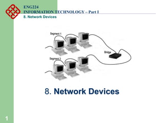
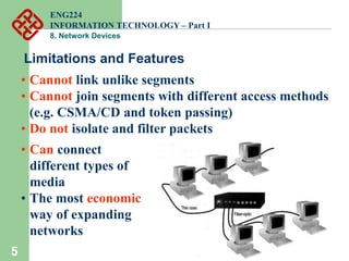
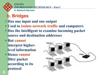
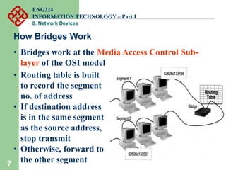
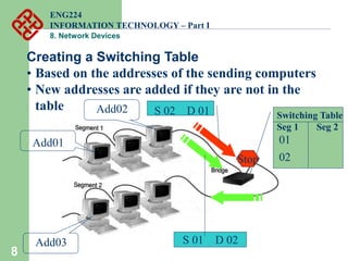
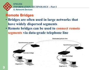
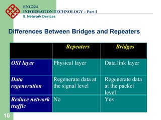
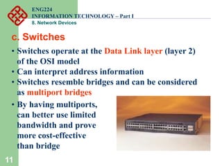
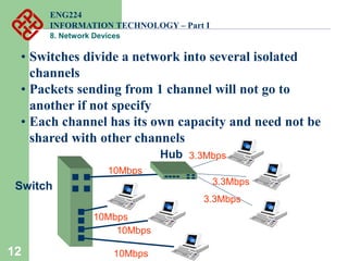
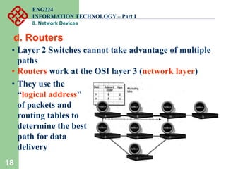
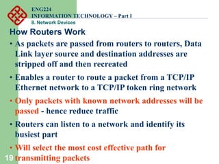
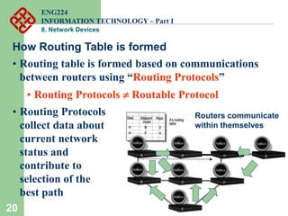
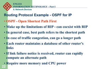
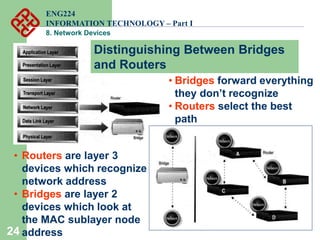
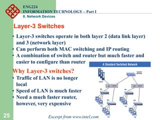
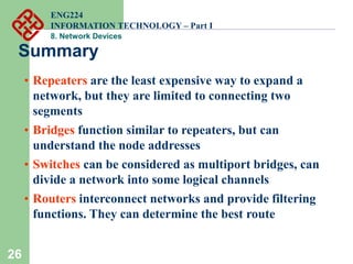
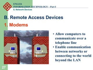
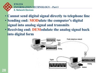
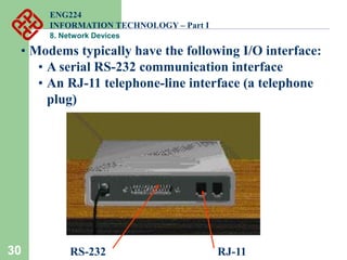
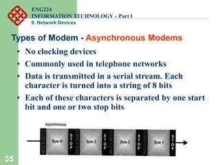
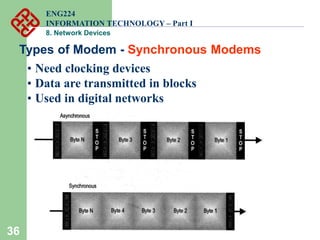
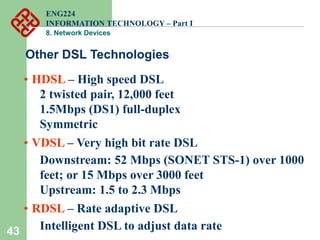
1
8. Network Devices
ENG224
INFORMATION TECHNOLOGY – Part I
8. Network Devices
2
Functions of network devices
• Separating (connecting) networks or
expanding network
• e.g. repeaters, hubs, bridges, routers,
brouters, switches, gateways
• Remote access
• e.g. 56K Modems and ADSL modems
ENG224
INFORMATION TECHNOLOGY – Part I
8. Network Devices
3
A. Expanding Network
• Networks cannot be made larger by simply
adding new computers and more cables
• Less efficient !!
• Can install components to
• segment (divide) large LAN to form smaller
LANs
• connect LANs
• Required components
• Repeaters, bridges, routers, brouters,
switches or gateways
ENG224
INFORMATION TECHNOLOGY – Part I
8. Network Devices
4
• Repeaters or hubs work at the OSI physical layer to
regenerate the network’s signal and resend them to
other segments
• Primitive hub can be viewed as a multiport repeater
• It regenerates data and broadcasts them to all
ports
a. Repeaters and Hubs
Hub
ENG224
INFORMATION TECHNOLOGY – Part I
8. Network Devices
5
Limitations and Features
• Cannot link unlike segments
• Cannot join segments with different access methods
(e.g. CSMA/CD and token passing)
• Do not isolate and filter packets
• Can connect
different types of
media
• The most economic
way of expanding
networks
ENG224
INFORMATION TECHNOLOGY – Part I
8. Network Devices
6
b. Bridges
• Has one input and one output
• Used to isolate network traffic and computers
• Has the intelligent to examine incoming packet
source and destination addresses
• But cannot
interpret higher-
level information
• Hence cannot
filter packet
according to its
protocol
ENG224
INFORMATION TECHNOLOGY – Part I
8. Network Devices
7
How Bridges Work
• Bridges work at the Media Access Control Sub-
layer of the OSI model
• Routing table is built
to record the segment
no. of address
• If destination address
is in the same segment
as the source address,
stop transmit
• Otherwise, forward to
the other segment
ENG224
INFORMATION TECHNOLOGY – Part I
8. Network Devices
8
Creating a Switching Table
• Based on the addresses of the sending computers
• New addresses are added if they are not in the
table
Add01
Add03
Add02
S 01 D 02
Switching Table
Seg 1 Seg 2
01
02
Stop
S 02 D 01
ENG224
INFORMATION TECHNOLOGY – Part I
8. Network Devices
9
Remote Bridges
• Bridges are often used in large networks that
have widely dispersed segments
• Remote bridges can be used to connect remote
segments via data-grade telephone line
ENG224
INFORMATION TECHNOLOGY – Part I
8. Network Devices
10
Differences Between Bridges and Repeaters
Repeaters Bridges
OSI layer Physical layer Data link layer
Data
regeneration
Regenerate data at
the signal level
Regenerate data
at the packet
level
Reduce network
traffic
No Yes
ENG224
INFORMATION TECHNOLOGY – Part I
8. Network Devices
11
c. Switches
Cisco Catalyst 2900 switch
• Switches operate at the Data Link layer (layer 2)
of the OSI model
• Can interpret address information
• Switches resemble bridges and can be considered
as multiport bridges
• By having multiports,
can better use limited
bandwidth and prove
more cost-effective
than bridge
ENG224
INFORMATION TECHNOLOGY – Part I
8. Network Devices
12
• Switches divide a network into several isolated
channels
• Packets sending from 1 channel will not go to
another if not specify
• Each channel has its own capacity and need not be
shared with other channels
10Mbps
10Mbps
10Mbps
10Mbps
Switch
Hub 3.3Mbps
3.3Mbps
3.3Mbps
ENG224
INFORMATION TECHNOLOGY – Part I
8. Network Devices
13
Advantages of Switches
• Switches divide a network into several isolated
channels (or collision domains)
• Reduce the possibility of collision
• Collision only occurs when two devices try to get access
to one channel
• Can be solved by buffering one of them for later access
• Each channel has its own network capacity
• Suitable for real-time applications, e.g. video
conferencing
• Since isolated, hence secure
• Data will only go to the destination, but not others
ENG224
INFORMATION TECHNOLOGY – Part I
8. Network Devices
14
Limitations of Switches
• Although contains buffers to accommodate bursts of
traffic, can become overwhelmed by heavy traffic
• Device cannot detect collision when buffer full
• CSMA/CD scheme will not work since the data
channels are isolated, not the case as in Ethernet
• Some higher level protocols do not detect error
• E.g. UDP
• Those data packets are continuously pumped to
the switch and introduce more problems
ENG224
INFORMATION TECHNOLOGY – Part I
8. Network Devices
15
Method of Switching - Cut Through Mode
Preamble Des. Add Sour. Add Length Data FCS
7
Bytes
2/6
Bytes
2/6
Bytes
2
Bytes
46 - 1500 Bytes 4
Bytes
1
Byte
• Read the first 14 bytes of each packet, then transmit
• Much faster
• Cannot detect corrupt packets
• Can propagate the corrupt packets to the network
• Best suited to small workgroups
ENG224
INFORMATION TECHNOLOGY – Part I
8. Network Devices
16
Method of Switching - Store and Forward Mode
• Read the whole packet before transmit
• Slower than the cut-through mode
• More accurate since corrupt packets can be detected
using the FCS
• More suit to large LAN since they will not propagate
error packets
10Mbps
DB
100Mbps
• Facilitate data
transfer between
segments of
different speed
ENG224
INFORMATION TECHNOLOGY – Part I
8. Network Devices
17
Using Switches to Create VLANs
• Switches can logically group together some ports to
form a virtual local area network (VLAN)
Switches can
be configured
to communicate
only within the
devices in the
group
Hub
Hub
Hub
SW1
SW2
SW3
VLAN1 VLAN2
ENG224
INFORMATION TECHNOLOGY – Part I
8. Network Devices
18
d. Routers
• Layer 2 Switches cannot take advantage of multiple
paths
• Routers work at the OSI layer 3 (network layer)
• They use the
“logical address”
of packets and
routing tables to
determine the best
path for data
delivery
ENG224
INFORMATION TECHNOLOGY – Part I
8. Network Devices
19
How Routers Work
• As packets are passed from routers to routers, Data
Link layer source and destination addresses are
stripped off and then recreated
• Enables a router to route a packet from a TCP/IP
Ethernet network to a TCP/IP token ring network
• Only packets with known network addresses will be
passed - hence reduce traffic
• Routers can listen to a network and identify its
busiest part
• Will select the most cost effective path for
transmitting packets
ENG224
INFORMATION TECHNOLOGY – Part I
8. Network Devices
20
How Routing Table is formed
• Routing table is formed based on communications
between routers using “Routing Protocols”
• Routing Protocols  Routable Protocol
• Routing Protocols
collect data about
current network
status and
contribute to
selection of the
best path
Routers communicate
within themselves
ENG224
INFORMATION TECHNOLOGY – Part I
8. Network Devices
21
Routing Protocol Example - RIP for IP Routing
• RIP (Routing Information Protocol) ― the oldest one
• Use no. of hops between nodes to determine best path
• Does not consider the network congestion condition
• Broadcast every 30 sec the routing table to
neighbouring routers to convey routing information
• RIP is limited to interpreting a maximum of 16 hops
• Not suitable for large network (e.g. Internet)
• Can create excessive network traffic due to
broadcasting
• May take a long time to reach the far reaches
ENG224
INFORMATION TECHNOLOGY – Part I
8. Network Devices
22
Routing Protocol Example - OSPF for IP
• OSPF - Open Shortest Path First
• Make up the limitations of RIP - can coexist with RIP
• In general case, best path refers to the shortest path
• In case of traffic congestion, can go a longer path
• Each router maintains a database of other router’s
links
• If link failure notice is received, router can rapidly
compute an alternate path
• Require more memory and CPU power
ENG224
INFORMATION TECHNOLOGY – Part I
8. Network Devices
23
Static and Dynamic Routers
Static Routers Dynamic Routers
Manual configuration
of routes
Manual configuration of the first
route. Automatic discovery of new
routes
Always use the same
route
Can select the best route
More secure Need manual configuration to
improve security
ENG224
INFORMATION TECHNOLOGY – Part I
8. Network Devices
24
• Routers are layer 3
devices which recognize
network address
• Bridges are layer 2
devices which look at
the MAC sublayer node
address
• Bridges forward everything
they don’t recognize
• Routers select the best
path
Distinguishing Between Bridges
and Routers
ENG224
INFORMATION TECHNOLOGY – Part I
8. Network Devices
25
Layer-3 Switches
• Layer-3 switches operate in both layer 2 (data link layer)
and 3 (network layer)
• Can perform both MAC switching and IP routing
• A combination of switch and router but much faster and
easier to configure than router
Why Layer-3 switches?
• Traffic of LAN is no longer
local
• Speed of LAN is much faster
• Need a much faster router,
however, very expensive
Excerpt from www.intel.com
ENG224
INFORMATION TECHNOLOGY – Part I
8. Network Devices
26
Summary
• Repeaters are the least expensive way to expand a
network, but they are limited to connecting two
segments
• Bridges function similar to repeaters, but can
understand the node addresses
• Switches can be considered as multiport bridges, can
divide a network into some logical channels
• Routers interconnect networks and provide filtering
functions. They can determine the best route
ENG224
INFORMATION TECHNOLOGY – Part I
8. Network Devices
27
• Allow computers to
communicate over a
telephone line
• Enable communication
between networks or
connecting to the world
beyond the LAN
B. Remote Access Devices
1. Modems
ENG224
INFORMATION TECHNOLOGY – Part I
8. Network Devices
28
• Cannot send digital signal directly to telephone line
• Sending end: MODulate the computer’s digital
signal into analog signal and transmits
• Receiving end: DEModulate the analog signal back
into digital form
ENG224
INFORMATION TECHNOLOGY – Part I
8. Network Devices
29
1 0 1 1 1
Amplitude
Modulation
Frequency
Modulation
Phase
Modulation
Normal
sine wave
ENG224
INFORMATION TECHNOLOGY – Part I
8. Network Devices
30 RS-232 RJ-11
• Modems typically have the following I/O interface:
• A serial RS-232 communication interface
• An RJ-11 telephone-line interface (a telephone
plug)
ENG224
INFORMATION TECHNOLOGY – Part I
8. Network Devices
31
Modem Standards
Standard bps Introduced Remarks
V.22bis 2,400 1984
V.32 9,600 1984
V.32bis 14,400 1991
V.32terbo 19,200 1993 Communicate only with
another V.32terbo
V.FastClass 28,800 1993 (V.FC)
V.34 28,800 1994 Improved V.FC
V.42bis 115,200 1995 With compression
V.90 56,000 1998 Resolved competition
between X2 and Flex56k
ENG224
INFORMATION TECHNOLOGY – Part I
8. Network Devices
32
• Baud rate - the number of symbol change per
second on the transmission line
• Bit per second (bps) - number of bits transmitted
per second
• In the past, they are identical
• With compression technique, a change of signal
can mean more than one bits
• 28.8kbaud can mean 115.2kbps when using
V.42bis
Modem Performance Measures
ENG224
INFORMATION TECHNOLOGY – Part I
8. Network Devices
33
How V.90 Works
• Modem speed is determined by channel noise level
• The noise level of traditional PSTN (public switch
telephone network) limits data rate to ~35kbps
• 56K modem technology assumes only one analog
link hence noise level is much lower
ENG224
INFORMATION TECHNOLOGY – Part I
8. Network Devices
34
Why V.90 cannot achieve 56kbps in practice?
• The actual data link is 64kbps
• To prevent interference and allow some overhead
data in communication, ITU recommends a lower
rate to 56 kbps
• However, 56 kbps is a theoretical number
• Depending on the quality and length of the analog
link, the actual data rate can range from 30kbps to
53kbps
ENG224
INFORMATION TECHNOLOGY – Part I
8. Network Devices
35
Types of Modem - Asynchronous Modems
• No clocking devices
• Commonly used in telephone networks
• Data is transmitted in a serial stream. Each
character is turned into a string of 8 bits
• Each of these characters is separated by one start
bit and one or two stop bits
ENG224
INFORMATION TECHNOLOGY – Part I
8. Network Devices
36
Types of Modem - Synchronous Modems
• Need clocking devices
• Data are transmitted in blocks
• Used in digital networks
ENG224
INFORMATION TECHNOLOGY – Part I
8. Network Devices
37
Comparison
• Asynchronous modems are relatively simple and
economic
• Large overhead - can be up to 20 to 27% of the
data traffic
• Error control is done by using parity bit or higher
layer protocols, e.g. MNP, V.42
• Synchronous modems are relatively complicated and
expensive
• Seldom use in home market
• Less overhead means higher efficiency
• More sophisticated error control protocol is
required
ENG224
INFORMATION TECHNOLOGY – Part I
8. Network Devices
38
2. ADSL
• ADSL stands for Asymmetric Digital Subscriber Line
• Particularly suitable for high speed multimedia
communications, general Internet applications
• Asymmetric - downstream 1.5 to 6.1Mbps
upstream 16 to 640kbps
• Digital - mainly for transmitting digital data
still require modulation and demodulation
• Subscriber line - make use of the analog connection
between household and CO
ENG224
INFORMATION TECHNOLOGY – Part I
8. Network Devices
39
Telephone
Company
2 to 3 miles
Splitter
normal
voice
data
high speed
low speed
ADSL Illustration
subscriber line
local loop
ENG224
INFORMATION TECHNOLOGY – Part I
8. Network Devices
40
Why Asymmetric?
• In general Internet applications, downstream often
requires a higher data rate than upstream
• Downstream - file download, video playback
• Upstream - click a link, send a form
• Reducing the
resource for
upstream can
provide more
resource for
downstream
ENG224
INFORMATION TECHNOLOGY – Part I
8. Network Devices
41
Why Subscriber Line?
• By better controlling the length and quality of the
analog connection between household and CO, a
higher data rate can be achieved
Data Rate Wire Gauge Distance Wire Size Distance
1.5 or 2 Mbps 24 AWG 18,000 ft 0.5 mm 5.5 km
1.5 or 2 Mbps 26 AWG 15,000 ft 0.4 mm 4.6 km
6.1 Mbps 24 AWG 12,000 ft 0.5 mm 3.7 km
6.1 Mbps 26 AWG 9,000 ft 0.4 mm 2.7 km
• More than 80% of the current installed subscriber
lines can fulfill this requirement
• Hence no extra cabling is required
ENG224
INFORMATION TECHNOLOGY – Part I
8. Network Devices
42
N
I
D
Modem
Telephone
Switch
Customer
Premises
Central Office
Copper
Loop
Telephony
Splitter
ADSL
Modem
T
N
I
Transport Network Link
(DSx; OCx; frame; ATM)
ISP POP
DNS
SNMP
DHCP
Internet
Firewall
Router
DSLAM
DSLAM - Digital subscriber
line access module (central
office ADSL modem pool)
Architecture of ADSL Services
ENG224
INFORMATION TECHNOLOGY – Part I
8. Network Devices
43
Other DSL Technologies
• HDSL – High speed DSL
2 twisted pair, 12,000 feet
1.5Mbps (DS1) full-duplex
Symmetric
• VDSL – Very high bit rate DSL
Downstream: 52 Mbps (SONET STS-1) over 1000
feet; or 15 Mbps over 3000 feet
Upstream: 1.5 to 2.3 Mbps
• RDSL – Rate adaptive DSL
Intelligent DSL to adjust data rate
ENG224
INFORMATION TECHNOLOGY – Part I
8. Network Devices

8 network devices

  • 1.
    1 8. Network Devices ENG224 INFORMATIONTECHNOLOGY – Part I 8. Network Devices
  • 2.
    2 Functions of networkdevices • Separating (connecting) networks or expanding network • e.g. repeaters, hubs, bridges, routers, brouters, switches, gateways • Remote access • e.g. 56K Modems and ADSL modems ENG224 INFORMATION TECHNOLOGY – Part I 8. Network Devices
  • 3.
    3 A. Expanding Network •Networks cannot be made larger by simply adding new computers and more cables • Less efficient !! • Can install components to • segment (divide) large LAN to form smaller LANs • connect LANs • Required components • Repeaters, bridges, routers, brouters, switches or gateways ENG224 INFORMATION TECHNOLOGY – Part I 8. Network Devices
  • 4.
    4 • Repeaters orhubs work at the OSI physical layer to regenerate the network’s signal and resend them to other segments • Primitive hub can be viewed as a multiport repeater • It regenerates data and broadcasts them to all ports a. Repeaters and Hubs Hub ENG224 INFORMATION TECHNOLOGY – Part I 8. Network Devices
  • 5.
    5 Limitations and Features •Cannot link unlike segments • Cannot join segments with different access methods (e.g. CSMA/CD and token passing) • Do not isolate and filter packets • Can connect different types of media • The most economic way of expanding networks ENG224 INFORMATION TECHNOLOGY – Part I 8. Network Devices
  • 6.
    6 b. Bridges • Hasone input and one output • Used to isolate network traffic and computers • Has the intelligent to examine incoming packet source and destination addresses • But cannot interpret higher- level information • Hence cannot filter packet according to its protocol ENG224 INFORMATION TECHNOLOGY – Part I 8. Network Devices
  • 7.
    7 How Bridges Work •Bridges work at the Media Access Control Sub- layer of the OSI model • Routing table is built to record the segment no. of address • If destination address is in the same segment as the source address, stop transmit • Otherwise, forward to the other segment ENG224 INFORMATION TECHNOLOGY – Part I 8. Network Devices
  • 8.
    8 Creating a SwitchingTable • Based on the addresses of the sending computers • New addresses are added if they are not in the table Add01 Add03 Add02 S 01 D 02 Switching Table Seg 1 Seg 2 01 02 Stop S 02 D 01 ENG224 INFORMATION TECHNOLOGY – Part I 8. Network Devices
  • 9.
    9 Remote Bridges • Bridgesare often used in large networks that have widely dispersed segments • Remote bridges can be used to connect remote segments via data-grade telephone line ENG224 INFORMATION TECHNOLOGY – Part I 8. Network Devices
  • 10.
    10 Differences Between Bridgesand Repeaters Repeaters Bridges OSI layer Physical layer Data link layer Data regeneration Regenerate data at the signal level Regenerate data at the packet level Reduce network traffic No Yes ENG224 INFORMATION TECHNOLOGY – Part I 8. Network Devices
  • 11.
    11 c. Switches Cisco Catalyst2900 switch • Switches operate at the Data Link layer (layer 2) of the OSI model • Can interpret address information • Switches resemble bridges and can be considered as multiport bridges • By having multiports, can better use limited bandwidth and prove more cost-effective than bridge ENG224 INFORMATION TECHNOLOGY – Part I 8. Network Devices
  • 12.
    12 • Switches dividea network into several isolated channels • Packets sending from 1 channel will not go to another if not specify • Each channel has its own capacity and need not be shared with other channels 10Mbps 10Mbps 10Mbps 10Mbps Switch Hub 3.3Mbps 3.3Mbps 3.3Mbps ENG224 INFORMATION TECHNOLOGY – Part I 8. Network Devices
  • 13.
    13 Advantages of Switches •Switches divide a network into several isolated channels (or collision domains) • Reduce the possibility of collision • Collision only occurs when two devices try to get access to one channel • Can be solved by buffering one of them for later access • Each channel has its own network capacity • Suitable for real-time applications, e.g. video conferencing • Since isolated, hence secure • Data will only go to the destination, but not others ENG224 INFORMATION TECHNOLOGY – Part I 8. Network Devices
  • 14.
    14 Limitations of Switches •Although contains buffers to accommodate bursts of traffic, can become overwhelmed by heavy traffic • Device cannot detect collision when buffer full • CSMA/CD scheme will not work since the data channels are isolated, not the case as in Ethernet • Some higher level protocols do not detect error • E.g. UDP • Those data packets are continuously pumped to the switch and introduce more problems ENG224 INFORMATION TECHNOLOGY – Part I 8. Network Devices
  • 15.
    15 Method of Switching- Cut Through Mode Preamble Des. Add Sour. Add Length Data FCS 7 Bytes 2/6 Bytes 2/6 Bytes 2 Bytes 46 - 1500 Bytes 4 Bytes 1 Byte • Read the first 14 bytes of each packet, then transmit • Much faster • Cannot detect corrupt packets • Can propagate the corrupt packets to the network • Best suited to small workgroups ENG224 INFORMATION TECHNOLOGY – Part I 8. Network Devices
  • 16.
    16 Method of Switching- Store and Forward Mode • Read the whole packet before transmit • Slower than the cut-through mode • More accurate since corrupt packets can be detected using the FCS • More suit to large LAN since they will not propagate error packets 10Mbps DB 100Mbps • Facilitate data transfer between segments of different speed ENG224 INFORMATION TECHNOLOGY – Part I 8. Network Devices
  • 17.
    17 Using Switches toCreate VLANs • Switches can logically group together some ports to form a virtual local area network (VLAN) Switches can be configured to communicate only within the devices in the group Hub Hub Hub SW1 SW2 SW3 VLAN1 VLAN2 ENG224 INFORMATION TECHNOLOGY – Part I 8. Network Devices
  • 18.
    18 d. Routers • Layer2 Switches cannot take advantage of multiple paths • Routers work at the OSI layer 3 (network layer) • They use the “logical address” of packets and routing tables to determine the best path for data delivery ENG224 INFORMATION TECHNOLOGY – Part I 8. Network Devices
  • 19.
    19 How Routers Work •As packets are passed from routers to routers, Data Link layer source and destination addresses are stripped off and then recreated • Enables a router to route a packet from a TCP/IP Ethernet network to a TCP/IP token ring network • Only packets with known network addresses will be passed - hence reduce traffic • Routers can listen to a network and identify its busiest part • Will select the most cost effective path for transmitting packets ENG224 INFORMATION TECHNOLOGY – Part I 8. Network Devices
  • 20.
    20 How Routing Tableis formed • Routing table is formed based on communications between routers using “Routing Protocols” • Routing Protocols  Routable Protocol • Routing Protocols collect data about current network status and contribute to selection of the best path Routers communicate within themselves ENG224 INFORMATION TECHNOLOGY – Part I 8. Network Devices
  • 21.
    21 Routing Protocol Example- RIP for IP Routing • RIP (Routing Information Protocol) ― the oldest one • Use no. of hops between nodes to determine best path • Does not consider the network congestion condition • Broadcast every 30 sec the routing table to neighbouring routers to convey routing information • RIP is limited to interpreting a maximum of 16 hops • Not suitable for large network (e.g. Internet) • Can create excessive network traffic due to broadcasting • May take a long time to reach the far reaches ENG224 INFORMATION TECHNOLOGY – Part I 8. Network Devices
  • 22.
    22 Routing Protocol Example- OSPF for IP • OSPF - Open Shortest Path First • Make up the limitations of RIP - can coexist with RIP • In general case, best path refers to the shortest path • In case of traffic congestion, can go a longer path • Each router maintains a database of other router’s links • If link failure notice is received, router can rapidly compute an alternate path • Require more memory and CPU power ENG224 INFORMATION TECHNOLOGY – Part I 8. Network Devices
  • 23.
    23 Static and DynamicRouters Static Routers Dynamic Routers Manual configuration of routes Manual configuration of the first route. Automatic discovery of new routes Always use the same route Can select the best route More secure Need manual configuration to improve security ENG224 INFORMATION TECHNOLOGY – Part I 8. Network Devices
  • 24.
    24 • Routers arelayer 3 devices which recognize network address • Bridges are layer 2 devices which look at the MAC sublayer node address • Bridges forward everything they don’t recognize • Routers select the best path Distinguishing Between Bridges and Routers ENG224 INFORMATION TECHNOLOGY – Part I 8. Network Devices
  • 25.
    25 Layer-3 Switches • Layer-3switches operate in both layer 2 (data link layer) and 3 (network layer) • Can perform both MAC switching and IP routing • A combination of switch and router but much faster and easier to configure than router Why Layer-3 switches? • Traffic of LAN is no longer local • Speed of LAN is much faster • Need a much faster router, however, very expensive Excerpt from www.intel.com ENG224 INFORMATION TECHNOLOGY – Part I 8. Network Devices
  • 26.
    26 Summary • Repeaters arethe least expensive way to expand a network, but they are limited to connecting two segments • Bridges function similar to repeaters, but can understand the node addresses • Switches can be considered as multiport bridges, can divide a network into some logical channels • Routers interconnect networks and provide filtering functions. They can determine the best route ENG224 INFORMATION TECHNOLOGY – Part I 8. Network Devices
  • 27.
    27 • Allow computersto communicate over a telephone line • Enable communication between networks or connecting to the world beyond the LAN B. Remote Access Devices 1. Modems ENG224 INFORMATION TECHNOLOGY – Part I 8. Network Devices
  • 28.
    28 • Cannot senddigital signal directly to telephone line • Sending end: MODulate the computer’s digital signal into analog signal and transmits • Receiving end: DEModulate the analog signal back into digital form ENG224 INFORMATION TECHNOLOGY – Part I 8. Network Devices
  • 29.
    29 1 0 11 1 Amplitude Modulation Frequency Modulation Phase Modulation Normal sine wave ENG224 INFORMATION TECHNOLOGY – Part I 8. Network Devices
  • 30.
    30 RS-232 RJ-11 •Modems typically have the following I/O interface: • A serial RS-232 communication interface • An RJ-11 telephone-line interface (a telephone plug) ENG224 INFORMATION TECHNOLOGY – Part I 8. Network Devices
  • 31.
    31 Modem Standards Standard bpsIntroduced Remarks V.22bis 2,400 1984 V.32 9,600 1984 V.32bis 14,400 1991 V.32terbo 19,200 1993 Communicate only with another V.32terbo V.FastClass 28,800 1993 (V.FC) V.34 28,800 1994 Improved V.FC V.42bis 115,200 1995 With compression V.90 56,000 1998 Resolved competition between X2 and Flex56k ENG224 INFORMATION TECHNOLOGY – Part I 8. Network Devices
  • 32.
    32 • Baud rate- the number of symbol change per second on the transmission line • Bit per second (bps) - number of bits transmitted per second • In the past, they are identical • With compression technique, a change of signal can mean more than one bits • 28.8kbaud can mean 115.2kbps when using V.42bis Modem Performance Measures ENG224 INFORMATION TECHNOLOGY – Part I 8. Network Devices
  • 33.
    33 How V.90 Works •Modem speed is determined by channel noise level • The noise level of traditional PSTN (public switch telephone network) limits data rate to ~35kbps • 56K modem technology assumes only one analog link hence noise level is much lower ENG224 INFORMATION TECHNOLOGY – Part I 8. Network Devices
  • 34.
    34 Why V.90 cannotachieve 56kbps in practice? • The actual data link is 64kbps • To prevent interference and allow some overhead data in communication, ITU recommends a lower rate to 56 kbps • However, 56 kbps is a theoretical number • Depending on the quality and length of the analog link, the actual data rate can range from 30kbps to 53kbps ENG224 INFORMATION TECHNOLOGY – Part I 8. Network Devices
  • 35.
    35 Types of Modem- Asynchronous Modems • No clocking devices • Commonly used in telephone networks • Data is transmitted in a serial stream. Each character is turned into a string of 8 bits • Each of these characters is separated by one start bit and one or two stop bits ENG224 INFORMATION TECHNOLOGY – Part I 8. Network Devices
  • 36.
    36 Types of Modem- Synchronous Modems • Need clocking devices • Data are transmitted in blocks • Used in digital networks ENG224 INFORMATION TECHNOLOGY – Part I 8. Network Devices
  • 37.
    37 Comparison • Asynchronous modemsare relatively simple and economic • Large overhead - can be up to 20 to 27% of the data traffic • Error control is done by using parity bit or higher layer protocols, e.g. MNP, V.42 • Synchronous modems are relatively complicated and expensive • Seldom use in home market • Less overhead means higher efficiency • More sophisticated error control protocol is required ENG224 INFORMATION TECHNOLOGY – Part I 8. Network Devices
  • 38.
    38 2. ADSL • ADSLstands for Asymmetric Digital Subscriber Line • Particularly suitable for high speed multimedia communications, general Internet applications • Asymmetric - downstream 1.5 to 6.1Mbps upstream 16 to 640kbps • Digital - mainly for transmitting digital data still require modulation and demodulation • Subscriber line - make use of the analog connection between household and CO ENG224 INFORMATION TECHNOLOGY – Part I 8. Network Devices
  • 39.
    39 Telephone Company 2 to 3miles Splitter normal voice data high speed low speed ADSL Illustration subscriber line local loop ENG224 INFORMATION TECHNOLOGY – Part I 8. Network Devices
  • 40.
    40 Why Asymmetric? • Ingeneral Internet applications, downstream often requires a higher data rate than upstream • Downstream - file download, video playback • Upstream - click a link, send a form • Reducing the resource for upstream can provide more resource for downstream ENG224 INFORMATION TECHNOLOGY – Part I 8. Network Devices
  • 41.
    41 Why Subscriber Line? •By better controlling the length and quality of the analog connection between household and CO, a higher data rate can be achieved Data Rate Wire Gauge Distance Wire Size Distance 1.5 or 2 Mbps 24 AWG 18,000 ft 0.5 mm 5.5 km 1.5 or 2 Mbps 26 AWG 15,000 ft 0.4 mm 4.6 km 6.1 Mbps 24 AWG 12,000 ft 0.5 mm 3.7 km 6.1 Mbps 26 AWG 9,000 ft 0.4 mm 2.7 km • More than 80% of the current installed subscriber lines can fulfill this requirement • Hence no extra cabling is required ENG224 INFORMATION TECHNOLOGY – Part I 8. Network Devices
  • 42.
    42 N I D Modem Telephone Switch Customer Premises Central Office Copper Loop Telephony Splitter ADSL Modem T N I Transport NetworkLink (DSx; OCx; frame; ATM) ISP POP DNS SNMP DHCP Internet Firewall Router DSLAM DSLAM - Digital subscriber line access module (central office ADSL modem pool) Architecture of ADSL Services ENG224 INFORMATION TECHNOLOGY – Part I 8. Network Devices
  • 43.
    43 Other DSL Technologies •HDSL – High speed DSL 2 twisted pair, 12,000 feet 1.5Mbps (DS1) full-duplex Symmetric • VDSL – Very high bit rate DSL Downstream: 52 Mbps (SONET STS-1) over 1000 feet; or 15 Mbps over 3000 feet Upstream: 1.5 to 2.3 Mbps • RDSL – Rate adaptive DSL Intelligent DSL to adjust data rate ENG224 INFORMATION TECHNOLOGY – Part I 8. Network Devices