
Recommended
Recommended
More Related Content
What's hot
What's hot (20)
Similar to CONTENT BASED IMAGE RETRIEVAL SYSTEM
Similar to CONTENT BASED IMAGE RETRIEVAL SYSTEM (20)
Recently uploaded
Recently uploaded (20)
CONTENT BASED IMAGE RETRIEVAL SYSTEM
- 1. CONTENT BASED IMAGE RETRIEVAL SYSTEM 1. INTRODUCTION 1.1 MOTIVATION: In many areas of commerce, government, academia, and hospitals, large collections of digital images are being created. Many of these collections are the product of digitizing existing collections of analogue photographs, diagrams, drawings, paintings, and prints. Usually, the only way of searching these collections was by keyword indexing, or simply by browsing. Digital images databases however, open the way to content-based searching. 1.2 PROBLEM DEFINITION: Since the 1970s Image Retrieval has become a very active research topic, with two major research communities, database management and computer vision. One is text-based and another is visual-based. Text-based image retrieval has become very popular since 1970s, which involves annotating the image with keywords, and use text-based database management systems (DBMS) to retrieve the images. In text- based image retrieval system, keywords of semantic information are attached to the images. They can be typed manually or by extracting the captions of the images. It is very efficient for simple and small image databases, since the whole database can be described by just few hundreds of keywords. But in the 1990s, several large leaps in development of processor, memory and storage made the size of image databases grow dramatically. As the image database and image size grow, there will be more images having different contents and the images having rich contents cannot be described by only several Semantic keywords. The demand of labor on annotating the images also rises dramatically. Retrieval image providing effective and efficient tool querying large image database. Information retrieval provides the textual representation of images. It requires the text descriptions to the respective images. Recent technology development in various fields has made large digital image databases practical. Well organized database and efficient browsing, storing, and 1
- 2. CONTENT BASED IMAGE RETRIEVAL SYSTEM retrieval algorithms are very important in such systems. Image retrieval techniques were developed to aid these components. Image Retrieval was originated from Information Retrieval, which has been very active research topic since 1940s. “We have huge amounts of information to which accurate and speedy access is becoming ever more difficult.” In principle, Information Retrieval is simple. It can be illustrated by a scene of a store of documents and a person (user of the store). He formulates a question to which the answer is a set of documents satisfying his question. He can obtain the set by reading all the documents in the store, retaining the relevant documents and discarding all the others. In this scene, it is a ’perfect’ retrieval. But in practice, we need to model the “read” process in both syntactic and semantic to extract useful information. The target of Information Retrieval is not only “how to extract useful information”, but also “how to measure relevance among documents”. These challenges also exist in Image Retrieval. Also the keywords are very dependent on the observer’s interest and they are subjective. Captions are not always precisely describing the picture. Indexing and searching a large image database via keywords are time- consuming and inefficient. Content Based Image Retrieval (CBIR) researches attempt to automate such complex process of retrieving images that are similar to the reference image or descriptions given. 1.3 OBJECTIVE OF PROJECT Content-based image retrieval also known as query by image content and content-based visual information retrieval problem of searching for digital images in large database. Content-based means the search will analyze the actual contents of image. The term content in this context might refer to colors, shapes, textures or any other information that can be derived from the image itself. The earliest use of the term Content Based Image Retrieval in the literature seems to be by Kato, was to describe his experiments in automatic retrieval of images from a database by color and shape features. The term has since been widely used to describe the process of retrieving desired images from a large collection on the basis 2
- 3. CONTENT BASED IMAGE RETRIEVAL SYSTEM of features (such as color,Texture and shape) that can be automatically extracted from the images themselves. The features used for retrieval can be either primitive or semantic, but the extraction process must be predominantly automatic. The ideal approach of querying an image database is using content semantics, which applies the human understanding about image. Unfortunately, extracting the semantic information in an image efficiently and accurately is still a question. Even with the most advanced implementation of computer vision, it is still not easy to identify an image of horses on a road. So, using low level features instead of semantics is still a more practical way. Until semantic extraction can be done automatically and accurately, image retrieval systems cannot be expected to find all correct images. They should select the most similar images to let the user choose the desired images. The number of images of retrieved set can be reduced by applying similarity measure that measures the perceptual similarity. A typical CBIR system consists of three major components and the variations of them depend on features used. • Feature extraction – Analyze raw image data to extract feature specific information. • Feature storage – Provide efficient storage for the extracted information, also help to improve searching speed. • Similarity measure – Measure the difference between images for determining the relevance between images. 3
- 4. CONTENT BASED IMAGE RETRIEVAL SYSTEM 2. LITERATURE SURVEY Literature survey is the most important step in software development process. Before developing the tool it is necessary to determine the time factor, economy n company strength. Once these things r satisfied, ten next step is to determine which operating system and language can be used for developing the tool. Once the programmers start building the tool the programmers need lot of external support. This support can be obtained from senior programmers, from book or from websites. Before building the system the above consideration r taken into account for developing the proposed system. 2.1 EXISTING SYSTEM In earlier days, image retrieving from large image database can be done by following ways. We will discuss briefly about the image retrieving of various steps • Automatic Image Annotation and Retrieval using Cross Media Relevance Models • Concept Based Query Expansion • Query System Bridging The Semantic Gap For Large Image Databases • Ontology-Based Query Expansion Widget for information Retrieval • Detecting image purpose in World-Wide Web documents 2.1.1 Automatic Image Annotation and Retrieval using Cross Media Relevance Models Libraries have traditionally used manual image annotation for indexing and then later retrieving their image collections. However, manual image annotation is an expensive and labor intensive procedure and hence there has been great interest in coming up with automatic ways to retrieve images based on content. Here, we propose an automatic approach to annotating and retrieving images based on a training set of images. We assume that regions in an image can be described using a small vocabulary of blobs. Blobs are generated from image features using clustering. Given a training 4
- 5. CONTENT BASED IMAGE RETRIEVAL SYSTEM set of images with annotations, we show that probabilistic models allow us to predict the probability of generating a word given the blobs in an image This may be used to automatically annotate and retrieve images given a word as a query. We show that relevance models. Allow us to derive these probabilities in a natural way. Experiments show that the annotation performance of this cross-media relevance model is almost six times as good (in terms of mean precision) than a model based on word-blob co-occurrence model and twice as good as a state of the art model derived from machine translation. Our approach shows the usefulness of using formal information retrieval models for the task of image annotation and retrieval. 2.1.2 Concept Based Query Expansion Query expansion methods have been studied for a long time - with debatable success in many instances. In this project we present a probabilistic query expansion model based on a similarity thesaurus which was constructed automatically. A similarity thesaurus reflects domain knowledge about the particular collection from which it is constructed. We address the two important issues with query expansion: the selection and the weighting of additional search terms. In contrast to earlier methods, our queries are expanded by adding those terms that are most similar to the concept of the query, rather than selecting terms that are similar to the query terms. Our experiments show that this kind of query expansion results in a notable improvement in the retrieval effectiveness when measured using both recall-precision and usefulness. 2.1.3 Query System Bridging the Semantic Gap for Large Image Databases We propose a novel system called HISA for organizing very large image databases. HISA implements the first known data structure to capture both the ontological knowledge and visual features for effective and efficient retrieval of images by either keywords, image examples, or both. HISA employs automatic image annotation technique, ontology analysis and statistical analysis of domain knowledge to precompile the data structure. Using these techniques, HISA is able to bridge the gap between the image semantics and the visual features, therefore providing more 5
- 6. CONTENT BASED IMAGE RETRIEVAL SYSTEM user-friendly and high performance queries. We demonstrate the novel data structure employed by HISA, the query algorithms, and the pre-computation process. 2.1.4 Ontology-Based Query Expansion Widget for information Retrieval In this project we present an ontology-based query expansion widget which utilizes the ontologies published in the ONKI Ontology Service. The widget can be integrated into a web page, e.g. a search system of a museum catalogue, enhancing the page by providing query expansion functionality. We have tested the system with general, domainspecic and spatiotemporal ontologies. 2.1.5 Detecting image purpose in World-Wide Web documents The number of World-Wide Web (WWW) documents available to users of the Internet is growing at an incredible rate. Therefore, it is becoming increasingly important to develop systems that aid users in searching, altering, and retrieving information from the Internet. Currently, only a few prototype systems catalog and index images in Web documents. To greatly improve the cataloging and indexing of images on the Web, we have developed a prototype rule-based system that detects the content images in Web documents [9]. Content images are images that are associated with the main content of Web documents, as opposed to a multitude of other images that exist in Web documents for different purposes, such as decorative, advertisement and logo images. We present a system that uses decision tree learning for automated rule induction for the content image detection system. The system uses visual features, text-related features and the document context of images in concert for fast and effective content image detection in Web documents. 2.2 DISADVANTAGES: • The performances of these systems are not satisfactory. • Time taking process. • Less iterative process. • No efficiency. 6
- 7. CONTENT BASED IMAGE RETRIEVAL SYSTEM 2.3 PROPOSED SYSTEM: Relevance feedback is an interactive process that starts with normal CBIR. The user input a query, and then the system extracts the image feature and measure the distance with images in the database. An initial retrieval list is then generated. User can choose the relevant image to further refine the query, and this process can be iterated many times until the user find the desired images. Digital images databases open the way for content-based searching. Content Based Image Retrieval occupies a well ranked position among the research areas as it provides the practical solution for narrowing the semantic gap between the image retrieval process and the human perception. The main objective of this paper is to propose a framework for region content based image retrieval based on a distributed clustered image dataset. The proposed framework introduces a new perspective to measure the similarity between the image query and the clustered dataset images. Moreover, a development by adopting three relevance feedback techniques is used to refine the results of the retrieval system which are the well known Query Point Movement and Query Expansion, besides to the proposed third technique which is Query Modified Re-Weighting technique. MODULES: • INDEXING: In Indexing module we are going to giving the numbering to all the images. According to the numbers this application is going to retrieving the images. • SEARCHING: In this module we are going search for the images whatever we selected for the search. 7
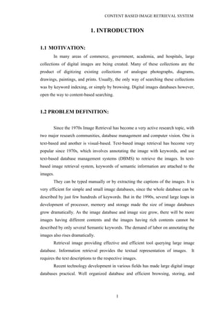
- 8. CONTENT BASED IMAGE RETRIEVAL SYSTEM Figure1: PROCESS DIAGRAM 8 Input Query Retrieval Result Feature Extractio n Similarit y measure Query update User’s Feedbac k Find all image s? Final Retrieval Result
- 9. CONTENT BASED IMAGE RETRIEVAL SYSTEM 3. ANALYSIS 3.1 PROBLEM STATEMENT: The problem involves entering an image as a query in a software application that is designed to employ CBIR techniques in extracting visual properties, and matching them. This is done to retrieve images in the database which are visually similar to query image. 3.2 APPROACH METHOD: The k-means algorithm Algorithm: k-means. The k-means algorithm for partitioning based on the mean value of the objects in the cluster. Input: The number of clusters k and a database containing n objects. Output: A set of k clusters that minimizes the squared-error criterion. Method: (1) arbitrarily choose k objects as the initial cluster centers: (2) repeat (3) (re)assign each object to the cluster to which the object is the most similar, based on the mean value of the objects in the cluster; (4) Update the cluster means, i.e., calculate the mean value of the objects for each cluster; (5) Until no change. 3.3 SOFTWARE REQUIREMENTS SPECIFICATION: Introduction: Software Requirements Specification plays an important role in creating quality software solutions. Specification is basically a representation process. Requirements are represented in a manner that ultimately leads to successful software implementation.The software requirements specification is produced at the culmination of the analysis task. The function and performance allocated to the 9
- 10. CONTENT BASED IMAGE RETRIEVAL SYSTEM software as a part of system engineering are refined by establishing a complete information description, a detailed functional and behavioral description, and indication of performance requirements and design constraints, appropriate validation criteria and other data pertinent to requirements. 3.3.1 SOFTWARE DEVELOPMENT LIFE CYCLE: The term software development life cycle model is a way of describing the planning, designing, coding, and testing of a software system, as well as the method in which these steps are implemented. A variety of life cycle models exist, but they all include the same constituent parts. All life cycle models take a project through several primary phases: a requirements-gathering phase, a design phase, a construction or implementation phase, and a testing phase. Each phase produces feedback that affects the next phase. For instance, the requirements gathered during the requirements phase influence the design, which is translated into working software code during the implementation phase. The software code is verified against the requirements during the testing phase. PROTOTYPE MODEL: The prototyping paradigm begins with requirements adhering. Developer and customer meet and dine the overall objectives for the software, identify whatever requirements are known, and outline areas where further definition is mandatory. A "quick design" then occurs. The quick design focuses on a representation of those aspects of the software that will be visible to the customer/user . The quick design leads to the construction of a prototype. The prototype is evaluated by the customer/user and used to refine requirements for the software to be developed. Iteration occurs as the prototype is tuned to satisfy the needs of the customer, while at the same time enabling the developer to better understand what needs to be done. Ideally, the prototype serves as a mechanism for identifying software requirements. If a working prototype is built, the developer attempts to use existing program fragments or applies tools that enable working programs to be generated quickly. 10
- 11. CONTENT BASED IMAGE RETRIEVAL SYSTEM RAD MODEL: Rapid application development (RAD) is an incremental software development process model that emphasizes an extremely short development cycle. The RAD model is a “high-speed” adaptation of the linear sequential model in which rapid development is achieved by using component-based construction. If requirements are well understood and project scope is constrained, the RAD process enables a development team to create a “fully functional system” within very short time periods (e.g., 60 to 90 days) . INCREMENTAL MODEL: The incremental model combines elements of the linear sequential model with the iterative philosophy of prototyping. Each linear sequence produces a deliverable “increment” of the software.When an incremental model is used, the first increment is often a core product. That is, basic requirements are addressed, but many supplementary features (some known, others unknown) remain undelivered. The core product is used by the customer (or undergoes detailed review). As a result of use and/or evaluation, a plan is developed for the next increment. The plan addresses the modification of the core product to better meet the needs of the customer and the delivery of additional features and functionality. This process is repeated following the delivery of each increment, until the complete product is produced. SPIRAL MODEL: The spiral model, originally proposed by Boehm , is an evolutionary software process model that couples the iterative nature of prototyping with the controlled and systematic aspects of the linear sequential model. It provides the potential for rapid development of incremental versions of the software. Using the spiral model, software is developed in a series of incremental releases. During early iterations, the incremental release might be a paper model or prototype. During later iterations,increasingly more complete versions of the engineered system are produced. 11
- 12. CONTENT BASED IMAGE RETRIEVAL SYSTEM CONCURRENT DEVELOPMENT MODEL: The concurrent process model can be represented schematically as a series of major technical activities, tasks, and their associated states. All activities exist concurrently but reside in different states. The concurrent process model defines a series of events that will trigger transitions from state to state for each of the software engineering activities. This generates the event analysis model correction which will trigger the analysis activity from the done state into the awaiting changes state. In reality, the concurrent process model is applicable to all types of software development and provides an accurate picture of the current state of a project. Rather than, confining software engineering activities to a sequence of events, it defines a network of activities. Each activity on the network exists simultaneously with other activities. Events generated within a given activity or at some other place in the activity network trigger transitions among the states of an activity WATER FALL MODEL: The model that is basically being followed is the WATER FALL MODEL, which states that the phases are organized in a linear order. First of all the feasibility study is done. Once that part is over the requirement analysis and project planning begins. If system exists one and modification and addition of new module is needed, analysis of present system can be used as basic model. The design starts after the requirement analysis is complete and the coding begins after the design is complete. Once the programming is completed, the testing is done. In this model the sequence of activities performed in a software development project are: - Requirement Analysis, Project Planning, System design, Detail design, Coding, Unit testing, System integration & testing, here the linear ordering of these activities is critical. End of the phase and the output of one phase is the input of other phase. The output of each phase is to be consistent with the overall requirement of the system. Some of the qualities of spiral model are also incorporated like after the 12
- 13. CONTENT BASED IMAGE RETRIEVAL SYSTEM people concerned with the project review completion of each of the phase the work done. WATER FALL MODEL was being chosen because all requirements were known beforehand and the objective of our software development is the computerization/automation of an already existing manual working system. 13
- 14. CONTENT BASED IMAGE RETRIEVAL SYSTEM Figure2: WATER FALL MODEL 14
- 15. CONTENT BASED IMAGE RETRIEVAL SYSTEM 3.3.2 Software Requirements: • Operating system :- Windows XP Professional • Front End :- JAVA, Swing • Tool :- Eclipse 3.3 3.3.3 Hardware Requirements: • System : Pentium IV 2.4 GHz. • Hard Disk : 40 GB. • Floppy Drive : 1.44 Mb. • Monitor : 15 VGA Colour. • Mouse : Logitech. • Ram : 256 Mb. 15
- 16. CONTENT BASED IMAGE RETRIEVAL SYSTEM 4. DESIGN INTRODUCTION: Software design sits at the technical kernel of the software engineering process and is applied regardless of the development paradigm and area of application. Design is the first step in the development phase for any engineered product or system. The designer’s goal is to produce a model or representation of an entity that will later be built. Beginning, once system requirement have been specified and analyzed, system design is the first of the three technical activities -design, code and test that is required to build and verify software. The importance can be stated with a single word “Quality”. Design is the place where quality is fostered in software development. Design provides us with representations of software that can assess for quality. Design is the only way that we can accurately translate a customer’s view into a finished software product or system. Software design serves as a foundation for all the software engineering steps that follow. Without a strong design we risk building an unstable system – one that will be difficult to test, one whose quality cannot be assessed until the last stage. During design, progressive refinement of data structure, program structure, and procedural details are developed reviewed and documented. System design can be viewed from either technical or project management perspective. From the technical point of view, design is comprised of four activities – architectural design, data structure design, interface design and procedural design. UNIFIED MODELING LANGUAGE: Building a model for a software system prior to its construction is as essential as having a blueprint for building a large building. Good models are essential for communication among project teams. As the complexity of the systems increases, so does the importance of good modeling techniques. • The unified modeling language allows the software engineer to express an analysis model using the modeling notation that is governed by a set of syntactic semantic and pragmatic rules. 16
- 17. CONTENT BASED IMAGE RETRIEVAL SYSTEM • A UML system is represented using five different views that describe the system from distinctly different perspective. Each view is defined by a set of diagram, which is as follows. 4.2 ARCHITTECTURAL VIEWS AND DIAGRAMS OF THE UML: The UML Meta model elements are organized into diagrams. Different diagrams are used for different purposes depending on the angle from which you are viewing the system. The different views are called “architectural views”. Architectural views facilitate the organization of knowledge, and diagrams enable the communication of knowledge. Then knowledge itself is within the model or set of models that focuses on the problem and solution. The architectural views and their diagrams are summarized below: • The “user model view” encompasses a problem and solution from the preservative of those individuals whose problem the solution addresses. The view presents the goals and objectives of the problem owners and their requirements of the solution. This view is composed of “use case diagrams”. These diagrams describe the functionality provided by a system to external integrators. These diagrams contain actors, use cases, and their relationships. 4.3 UML DIAGRAMS: Every complex system is best approached through a small set of nearly independent views of a model; no single viewer is sufficient. Every model may be expressed at different levels of fidelity. The best models are connected to reality. The UML defines nine graphical diagrams. 1. Class diagram 2. Object diagram 3. Use-case diagram 4. Sequence diagram 5. Collaboration diagram 6. Activity diagram 17
- 18. CONTENT BASED IMAGE RETRIEVAL SYSTEM 7. State Chart diagram 8. Component diagram 9. Deployment diagram CLASS DIAGRAM: Class diagrams are the most common diagrams found in modeling object- oriented systems. A class diagram shows a set of classes, interfaces, and collaborations and their relationships. Graphically, a class diagram is a collection of vertices and arcs. USE CASE DIAGRAM: Use Case diagrams are one of the five diagrams in the UML for modeling the dynamic aspects of systems(activity diagrams, sequence diagrams, state chart diagrams and collaboration diagrams are the four other kinds of diagrams in the UML for modeling the dynamic aspects of systems). Use Case diagrams are central to modeling the behavior of the system, a sub-system, or a class. Each one shows a set of use cases and actors and relationships. SEQUENCE DIAGRAM: A sequence diagram is an interaction diagram that emphasizes the time ordering of the messages. Graphically, a sequence diagram is a table that shows objects arranged along the X-axis and messages, ordered in increasing time, along the Y-axis. COLABORATION DIAGRAM: Collaboration diagrams render how behavior is realized by components with in a system. These diagrams contain classes, associations, and their message exchanges with in a collaboration to accomplish a purpose. In generic form, these diagrams describe a set of classes and associations involved in message exchange sequences. In instance form(scenarios), these diagrams describe a set of objects of those classes links confirming to the associations, and one actual 18
- 19. CONTENT BASED IMAGE RETRIEVAL SYSTEM message exchange sequence that inconsistent with the generic form and uses those objects and links ACTIVITY DIAGRAM: An Activity Diagram is essentially a flow chart showing flow of control from activity to activity. They are used to model the dynamic aspects of as system. They can also be used to model the flow of an object as it moves from state to state at different points in the flow of control. STATE CHART DIAGRAM: A state chart diagram shows a state machine. State chart diagrams are used to model the dynamic aspects of the system. For the most part this involves modeling the behavior of the reactive objects. A reactive object is one whose behavior is best characterized by its response to events dispatched from outside its context. A reactive object has a clear lifeline whose current behavior is affected by its past. Graphically a state chart diagram is a collection of vertices and arcs. COMPONENT DIAGRAM: A component diagram shows a set of components and their relationships. We use the component diagram to illustrate the static implementation view of a system. Component diagrams are related to class diagrams in that a component typically maps to one or more classes, interfaces, or collaborations. DEPLOYMENT DIAGRAM: A deployment diagram shows a set of nodes and their relationships. We use deployment diagrams to illustrate the static deployment view of architecture. Deployment diagrams are related to component diagrams in that a node typically encloses one or more components. 19
- 20. CONTENT BASED IMAGE RETRIEVAL SYSTEM 4.1 UML DIAGRAMS USE CASE DIAGRAM: 20
- 21. CONTENT BASED IMAGE RETRIEVAL SYSTEM CLASS DIAGRAM: 21
- 22. CONTENT BASED IMAGE RETRIEVAL SYSTEM SEQUENCE DIAGRAM: 22
- 23. CONTENT BASED IMAGE RETRIEVAL SYSTEM COLLABORATION DIAGRAM: 23
- 24. CONTENT BASED IMAGE RETRIEVAL SYSTEM STATE CHART DIAGRAM: 24
- 25. CONTENT BASED IMAGE RETRIEVAL SYSTEM COMPONENT DIAGRAM: 25
- 26. CONTENT BASED IMAGE RETRIEVAL SYSTEM DEPLOYMENT DIAGRAM: 26
- 27. CONTENT BASED IMAGE RETRIEVAL SYSTEM 5. IMPLEMENTATION SOFTWARE DESCRIPTION: JAVA: Java is a set of several computer software products and specifications from Sun Microsystems (which has since merged with Oracle Corporation), that together provide a system for developing application software and deploying it in a cross-platform computing environment. Java is used in a wide variety of computing platforms from embedded devices and mobile phones on the low end, to enterprise servers and supercomputers on the high end. While less common, Java applets are sometimes used to provide improved and secure functions while browsing the World Wide Web on desktop computers. Writing in the Java programming language is the primary way to produce code that will be deployed as Java bytecode. There are, however, bytecodecompilers available for other languages such as Ada, JavaScript, Python, and Ruby. Several new languages have been designed to run natively on theJava Virtual Machine (JVM), such as Scala, Clojure and Groovy. Java syntax borrows heavily from C and C++, but object-oriented features are modeled after Smalltalk and Objective-C.[6] Java eliminates certain low-level constructs such as pointers and has a very simple memory model where every object is allocated on the heap and all variables of object types are references. Memory management is handled through integrated automatic garbage collection performed by the JVM An edition of the Java platform is the name for a bundle of related programs from Sun that allow for developing and running programs written in the Java programming language. The platform is not specific to any one processor or operating system, but rather an execution engine (called a virtual machine) and a compiler with a set of libraries that are implemented for various hardware and operating systems so that Java programs can run identically on all of them. • Java Card: A technology that allows small Java-based applications (applets) to be run securely on smart cards and similar small-memory devices. • Java ME (Micro Edition): Specifies several different sets of libraries (known as profiles) for devices with limited storage, display, and power capacities. 27
- 28. CONTENT BASED IMAGE RETRIEVAL SYSTEM Often used to develop applications for mobile devices, PDAs, TV set-top boxes, and printers. • Java SE (Standard Edition): For general-purpose use on desktop PCs, servers and similar devices. • Java EE (Enterprise Edition): Java SE plus various APIs useful for multi- tier client–server enterprise applications. The Java platform consists of several programs, each of which provides a portion of its overall capabilities. For example, the Java compiler, which converts Java source code into Java byte code (an intermediate language for the JVM), is provided as part of the Java Development Kit (JDK). The Java Runtime Environment (JRE), complementing the JVM with a just-in-time (JIT) compiler, converts intermediate byte code into native machine code on the fly. An extensive set of libraries are also part of the Java platform. The essential components in the platform are the Java language compiler, the libraries, and the runtime environment in which Java intermediate byte code "executes" according to the rules laid out in the virtual machine specification. Java Virtual Machine: The heart of the Java platform is the concept of a "virtual machine" that executes Java byte code programs. This byte code is the same no matter what hardware or operating system the program is running under. There is a JIT(Just In Time) compiler within the Java Virtual Machine, or JVM. The JIT compiler translates the Java bytecode into native processor instructions at run-time and caches the native code in memory during execution. The use of bytecode as an intermediate language permits Java programs to run on any platform that has a virtual machine available. The use of a JIT compiler means that Java applications, after a short delay during loading and once they have "warmed up" by being all or mostly JIT-compiled, tend to run about as fast as native programs. Since JRE version 1.2, Sun's JVM implementation has included a just-in- time compiler instead of an interpreter. Although Java programs are cross-platform or platform independent, the code of the Java Virtual Machines (JVM) that execute these programs is not. Every supported operating platform has its own JVM. 28
- 29. CONTENT BASED IMAGE RETRIEVAL SYSTEM Class libraries: In most modern operating systems (OSs), a large body of reusable code is provided to simplify the programmer's job. This code is typically provided as a set of dynamically loadable libraries that applications can call at runtime. Because the Java platform is not dependent on any specific operating system, applications cannot rely on any of the pre-existing OS libraries. Instead, the Java platform provides a comprehensive set of its own standard class libraries containing much of the same reusable functions commonly found in modern operating systems. Most of the system library is also written in Java. For instance, Swing library paints the user interface and handles the events itself, eliminating many subtle differences between how different platforms handle even similar components. The Java class libraries serve three purposes within the Java platform. First, like other standard code libraries, the Java libraries provide the programmer a well- known set of functions to perform common tasks, such as maintaining lists of items or performing complex string parsing. Second, the class libraries provide an abstract interface to tasks that would normally depend heavily on the hardware and operating system. Tasks such as network access and file access are often heavily intertwined with distinctive implementations of each platform. The java.net andjava.io libraries implement an abstraction layer in native OS code, then provide a standard interface for the Java applications to perform those tasks. Finally, when some underlying platform does not support all of the features a Java application expects, the class libraries work to gracefully handle the absent components, either by emulation to provide a substitute, or at least by providing a consistent way to check for the presence of a specific feature Implementation is the stage of the project when the theoretical design is turned out into a working system. Thus it can be considered to be the most critical stage in achieving a successful new system and in giving the user, confidence that the new system will work and be effective. The implementation stage involves careful planning, investigation of the existing system and it’s constraints on implementation, designing of methods to achieve changeover and evaluation of changeover methods. 29
- 30. CONTENT BASED IMAGE RETRIEVAL SYSTEM 6. OUTPUT SCREENS Click on “open dir…” and select a folder 30
- 31. CONTENT BASED IMAGE RETRIEVAL SYSTEM First index a particular folder. So that retrieval will be fast. 31
- 32. CONTENT BASED IMAGE RETRIEVAL SYSTEM A folder is selected and it has been indexed 32
- 33. CONTENT BASED IMAGE RETRIEVAL SYSTEM The method of retrieval is selected. Here, edge histogram. 33
- 34. CONTENT BASED IMAGE RETRIEVAL SYSTEM Select a image to give as input 34
- 35. CONTENT BASED IMAGE RETRIEVAL SYSTEM After selecting the method of retrieval , searching is performed. 35
- 36. CONTENT BASED IMAGE RETRIEVAL SYSTEM An image have been opened to retrieve the resembling image. 36
- 37. CONTENT BASED IMAGE RETRIEVAL SYSTEM Resembling images have been retrieved. 37
- 38. CONTENT BASED IMAGE RETRIEVAL SYSTEM We can see number of files are indexed 38
- 39. CONTENT BASED IMAGE RETRIEVAL SYSTEM Color layout is selected for image retrieval. 39
- 40. CONTENT BASED IMAGE RETRIEVAL SYSTEM Select image to search for.. 40
- 41. CONTENT BASED IMAGE RETRIEVAL SYSTEM Similar Images have been retrieved 41
- 42. CONTENT BASED IMAGE RETRIEVAL SYSTEM Image is retrieved by index number 42
- 43. CONTENT BASED IMAGE RETRIEVAL SYSTEM Select a dimension to search 43
- 44. CONTENT BASED IMAGE RETRIEVAL SYSTEM Select a image to create a result 44
- 45. CONTENT BASED IMAGE RETRIEVAL SYSTEM 7. TESTING INTRODUCTION: Unit testing: Unit testing involves the design of test cases that validate that the internal program logic is functioning properly, and that program inputs produce valid outputs. All decision branches and internal code flow should be validated. It is the testing of individual software units of the application .it is done after the completion of an individual unit before integration. This is a structural testing, that relies on knowledge of its construction and is invasive. Unit tests perform basic tests at component level and test a specific business process, application, and/or system configuration. Unit tests ensure that each unique path of a business process performs accurately to the documented specifications and contains clearly defined inputs and expected results. Integration testing: Integration tests are designed to test integrated software components to determine if they actually run as one program. Testing is event driven and is more concerned with the basic outcome of screens or fields. Integration tests demonstrate that although the components were individually satisfaction, as shown by successfully unit testing, the combination of components is correct and consistent. Integration testing is specifically aimed at exposing the problems that arise from the combination of components. Functional testing: Functional tests provide systematic demonstrations that functions tested are available as specified by the business and technical requirements, system documentation, and user manuals. Functional testing is centered on the following items: 45
- 46. CONTENT BASED IMAGE RETRIEVAL SYSTEM Valid Input : identified classes of valid input must be accepted. Invalid Input : identified classes of invalid input must be rejected. Functions : identified functions must be exercised. Output : identified classes of application outputs must be exercised. Systems/Procedures: interfacing systems or procedures must be invoked. Organization and preparation of functional tests is focused on requirements, key functions, or special test cases. In addition, systematic coverage pertaining to identify Business process flows; data fields, predefined processes, and successive processes must be considered for testing. Before functional testing is complete, additional tests are identified and the effective value of current tests is determined. System Testing: System testing ensures that the entire integrated software system meets requirements. It tests a configuration to ensure known and predictable results. An example of system testing is the configuration oriented system integration test. System testing is based on process descriptions and flows, emphasizing pre-driven process links and integration points. White Box Testing: White Box Testing is a testing in which in which the software tester has knowledge of the inner workings, structure and language of the software, or at least its purpose. It is purpose. It is used to test areas that cannot be reached from a black box level. Black Box Testing: Black Box Testing is testing the software without any knowledge of the inner workings, structure or language of the module being tested. Black box tests, as most other kinds of tests, must be written from a definitive source document, such as specification or requirements document, such as specification or 46
- 47. CONTENT BASED IMAGE RETRIEVAL SYSTEM requirements document. It is a testing in which the software under test is treated, as a black box .you cannot “see” into it. The test provides inputs and responds to outputs without considering how the software works. 7.1 DESIGN OF TEST CASES AND SCENARIOS 7.2 VALIDATION: As per given Software Requirements and Hardware Requirements, project has been fulfilled all the Requirements and works efficiently. we validated by considering above Test Cases . 8. CONCLUSION TEST CASE NUMBER DESCRIPTION EXPECTED OUTPUT OUTPUT RESULT 1 Indexing a folder and searching other folder Invalid Retrieving Invalid Retrieving success 2 Searching without Indexing Invalid Retrieving Invalid Retrieving success 3 Indexing and Searching same folder Similarity images are retrieved Similarity images are retrieved success 4 Browsing with invalid Index number Invalid retrieving Invalid Retrieving success 47
- 48. CONTENT BASED IMAGE RETRIEVAL SYSTEM Among the objectives of this paper performed to design, implement and test a sketch-based image retrieval system. Two main aspects were taken into account. The retrieval process has to be unconventional and highly interactive. The robustness of the method is essential in some degree of noise, which might also be in case of simple images. The drawn image without modification cannot be compared with color image, or its edge representation. Alternatively a distance transform step was introduced. The simple smoothing and edge detection based method was improved, which had a similar importance as the previous step. FUTURE SCOPE: At the tests the effectiveness of EHD and the dynamically parameterized HOG implementation was compared. It was examined with more databases. In our experience the HOG in more cases was much better than the EHD based retrieval. However, the situation is not so simple. The edge histogram descriptor can mainly look better for information poor sketches, while in other case better results can be achieved for more detailed. This is due to the sliding window solution of HOG. REFERENCES 48
- 49. CONTENT BASED IMAGE RETRIEVAL SYSTEM [1] Multimedia Content Description Interface – Part 3: Visual, ISO/IEC JTC1/SC29/WG11/N4062, 2008. [2] J. Wang and G. Wiederhold, “SIMPLIcity: Semantics-Sensitive Integrated Matching for Picture Libraries,” IEEE Transactions On Pattern Analysis And Machine Intelligence, vol. 23, no. 8, pp. 1-17, September 2008. [3] M. Swain and D. Ballard, “Color indexing,” International Journal of Computer Vision, vol.. 7, no.1, pp. 11-32, 2008. [4] K. Hirata and T. Kato, "Query by visual example, content based image retrieval," Advances in Database Technology-EDBT'92, vol. 580, pp. 56-71, A. Pirotte, C.Delobel, and G. Gottlob, Eds., 2006, Springer-Verlag. [5] J. Jeon, V. Lavrenko, and R. Manmatha, “Automatic Image Annotation and Retrieval Using Cross-Media Relevance Models,” Proc. 26th Ann. Int’l ACM SIGIR Conf. Research and Development in Information Retrieval (SIGIR ’03), pp. 119-126, 2003. [6] J. Kalervo, K. Jaana, and N. Timo, “ExpansionTool: Concept-Based Query Expansion and Construction,” Information Retrieval, vol. 4, no. 3, pp. 231- 255, 2001. [7] G. Chen, X. Li, L. Shou, J. Dong, and C. Chen, “HISA: A Query System Bridging the Semantic Gap for Large Image Databases (Demo),” Proc. 32nd Int’l Conf. Very Large Data Bases (VLDB ’06), pp. 1187-1190, 2006. [8] X.Y. Li, L.D. Shou, G. Chen, and K.-L. Tan, “An Image-Semantic Ontological Framework for Large Image Databases (Poster),” Proc. 12th Int’l Conf. Database Systems for Advanced Applications (DASFAA ’07), pp. 1050-1053, 2007. [9] J.R. Paek and S. Smith, “Detecting Image Purpose in World-Wide Web Documents,” Proc. IS&T/SPIE Symp. Electronic Imaging: Science and Technology— Document Recognition, vol. 3305, pp. 151- 158, Jan. 1998. [10] A.W.M. Smeulders, M. Worring, S. Santini, A. Gupta, and R. Jain, “Content- Based Image Retrieval at the End of the Early Years,” IEEE Trans. Pattern Analysis and Machine Intelligence, vol. 22, no. 12, pp. 1349-1380, Dec. 2000. APPENDIX SAMPLE CODE: 49
- 50. CONTENT BASED IMAGE RETRIEVAL SYSTEM public class MainFrame extends JFrame { private Color highlightHoverColor = Color.decode("#dddddd"); private Color highlightSelectColor = Color.decode("#eeeeee"); private SearchResultsTableModel tableModel = new SearchResultsTableModel(); private IndexReader browseReader = null; public MainFrame() { try { UIManager.setLookAndFeel(UIManager.getSystemLookAndFeelClassName( )); } catch (Exception e) { } initComponents(); try { Image icon = ImageIO.read(getClass().getResource("/resources/viewmag16.png")); if (icon!=null) setIconImage(icon); } catch (IOException ex) { Logger.getLogger(MainFrame.class.getName()).log(Level.SEVERE, null, ex); } selectboxDocumentBuilder.setSelectedIndex(5); buttonSwitchIndex.setBackground(highlightSelectColor); DropTarget t = new DropTarget(searchPanel, new DropTargetListener() { public void dragEnter(DropTargetDragEvent dtde) { } public void dragOver(DropTargetDragEvent dtde) { 50
- 51. CONTENT BASED IMAGE RETRIEVAL SYSTEM } public void dropActionChanged(DropTargetDragEvent dtde) { } public void dragExit(DropTargetEvent dte) { } public void drop(DropTargetDropEvent dtde) { try { Transferable tr = dtde.getTransferable(); DataFlavor[] flavors = tr.getTransferDataFlavors(); for (int i = 0; i < flavors.length; i++) { System.out.println("Possible flavor: " + flavors[i].getMimeType()); if (flavors[i].isFlavorJavaFileListType()) { dtde.acceptDrop(DnDConstants.ACTION_COPY_OR_MOVE); java.util.List list = (java.util.List) tr.getTransferData(flavors[i]); textfieldSearchImage.setText(list.get(0).toString()); dtde.dropComplete(true); return; } } } catch (Exception e) { e.printStackTrace(); } } }); } textfieldIndexDir.setEditable(false); textfieldIndexDir.addActionListener(new java.awt.event.ActionListener() { 51
- 52. CONTENT BASED IMAGE RETRIEVAL SYSTEM public void actionPerformed(java.awt.event.ActionEvent evt) { textfieldIndexDirActionPerformed(evt); } }); buttonOpenDir.setText(bundle.getString("button.open.indexdirectory")); // NOI18N buttonOpenDir.addActionListener(new java.awt.event.ActionListener() { public void actionPerformed(java.awt.event.ActionEvent evt) { buttonOpenDirActionPerformed(evt); } }); buttonStartIndexing.setText(bundle.getString("button.start.indexing")); // NOI18N buttonStartIndexing.addActionListener(new java.awt.event.ActionListener() { public void actionPerformed(java.awt.event.ActionEvent evt) { buttonStartIndexingActionPerformed(evt); } }); progressBarIndexing.setFocusable(false); progressBarIndexing.setName(bundle.getString("progressbar.indexing.name")); / / NOI18N progressBarIndexing.setString(bundle.getString("progressbar.indexing.name")); // NOI18N progressBarIndexing.setStringPainted(true); textfieldSearchImage.setEditable(false); buttonOpenImage.setText(bundle.getString("button.open.searchimage")); // NOI18N buttonOpenImage.setActionCommand(bundle.getString("openImageButton")); // NOI18N buttonOpenImage.addActionListener(new java.awt.event.ActionListener() { 52
- 53. CONTENT BASED IMAGE RETRIEVAL SYSTEM public void actionPerformed(java.awt.event.ActionEvent evt) { buttonOpenImageActionPerformed(evt); } }); buttonStartSearch.setText(bundle.getString("button.start.search")); // NOI18N buttonStartSearch.addActionListener(new java.awt.event.ActionListener() { public void actionPerformed(java.awt.event.ActionEvent evt) { buttonStartSearchActionPerformed(evt); } }); progressSearch.setString("Search state ..."); progressSearch.setStringPainted(true); buttonStartMosaicing.setText(bundle.getString("button.start.search")); // NOI18N buttonStartMosaicing.setToolTipText(bundle.getString("mosaic.startButton.toolt ip")); // NOI18N buttonStartMosaicing.addActionListener(new java.awt.event.ActionListener() { public void actionPerformed(java.awt.event.ActionEvent evt) { buttonStartMosaicingActionPerformed(evt); } }); progressMosaic.setToolTipText(bundle.getString("mosaic.progress.tooltip")); // NOI18N progressMosaic.setString(bundle.getString("progressbar.mosaic.name")); // NOI18N progressMosaic.setStringPainted(true); labelMosaicTitle.setFont(new java.awt.Font("Tahoma", 1, 18)); labelMosaicTitle.setText("Select image to create Mosaic:"); mosaicTileCountSlider.setPaintLabels(true); 53
- 54. CONTENT BASED IMAGE RETRIEVAL SYSTEM mosaicTileCountSlider.setToolTipText(bundle.getString("mosaic.slider.tooltip") ); // NOI18N mosaicTileCountSlider.addChangeListener(new javax.swing.event.ChangeListener() { public void stateChanged(javax.swing.event.ChangeEvent evt) { mosaicTileCountSliderStateChanged(evt); } }); jLabel12.setText("Number of tiles:"); jLabel12.setVerticalAlignment(javax.swing.SwingConstants.BOTTOM); mosaicImageLable.setBackground(new java.awt.Color(255, 255, 255)); mosaicImageLable.setHorizontalAlignment(javax.swing.SwingConstants.CENT ER); mosaicImageLable.setBorder(new javax.swing.border.LineBorder(new java.awt.Color(0, 0, 0), 1, true)); mosaicImageLable.setDoubleBuffered(true); mosaicImageLable.setHorizontalTextPosition(javax.swing.SwingConstants.CEN TER); mosaicImageLable.setMinimumSize(new java.awt.Dimension(260, 260)); buttonMosaicSave.setText("Save result ...."); buttonMosaicSave.setToolTipText(bundle.getString("mosaic.saveButton.tooltip" )); private void vieMenuStartPageActionPerformed(java.awt.event.ActionEvent evt) {//GEN-FIRST:event_vieMenuStartPageActionPerformed ((CardLayout) topPane.getLayout()).first(topPane); } public static void main(String args[]) { java.awt.EventQueue.invokeLater(new Runnable() { public void run() { new MainFrame().setVisible(true); 54
- 55. CONTENT BASED IMAGE RETRIEVAL SYSTEM } }); } 55