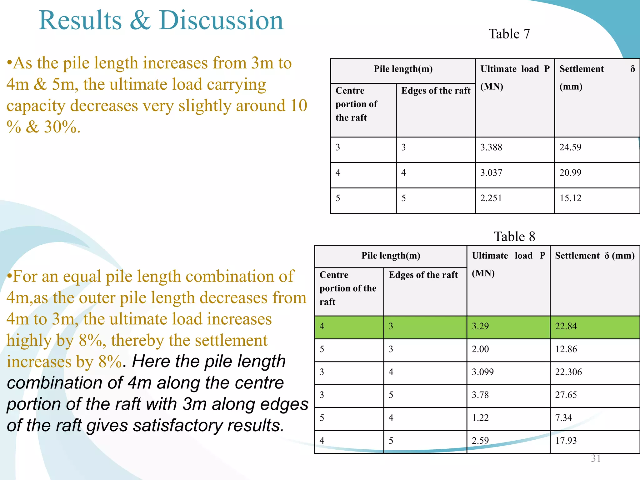
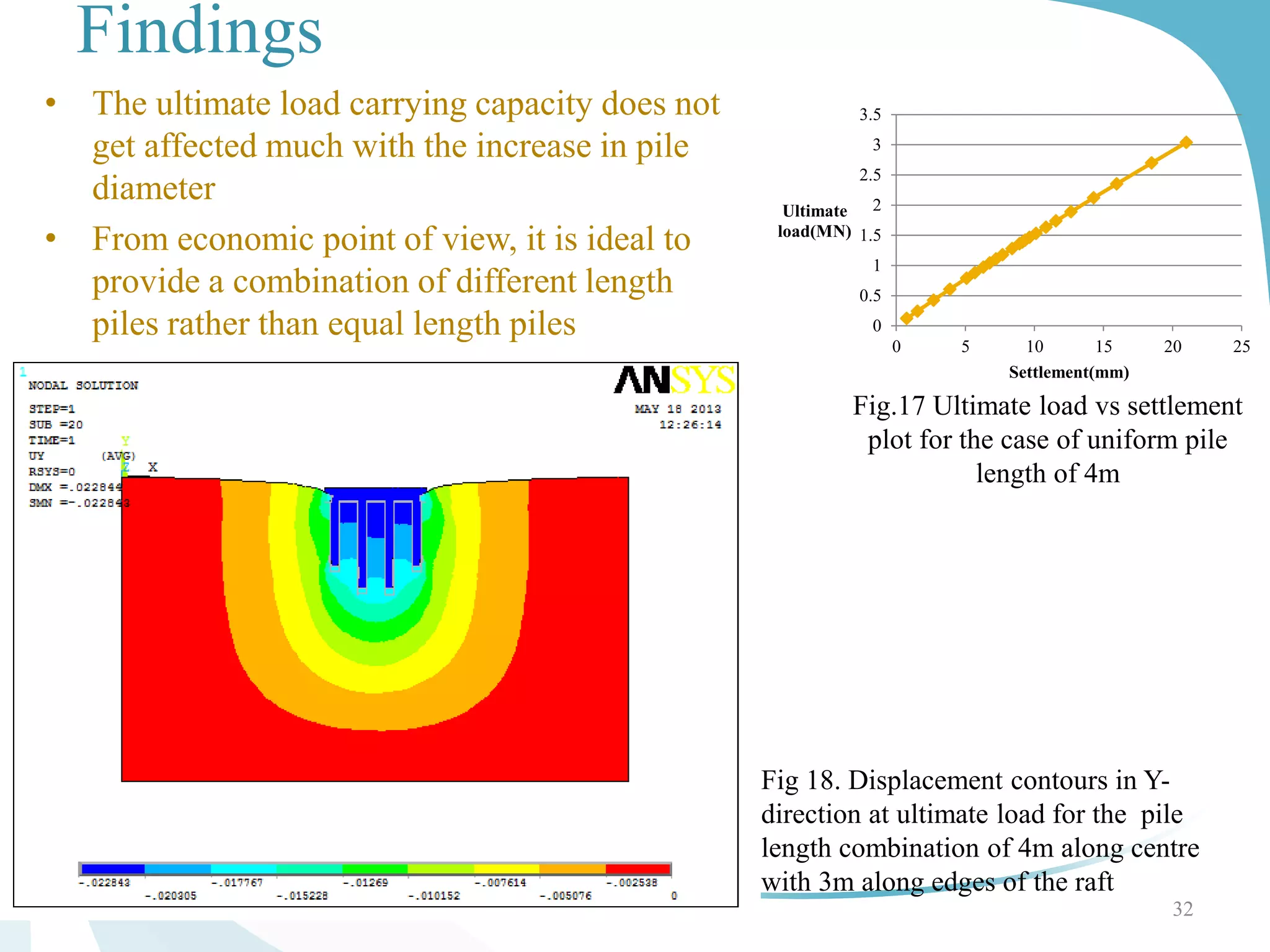
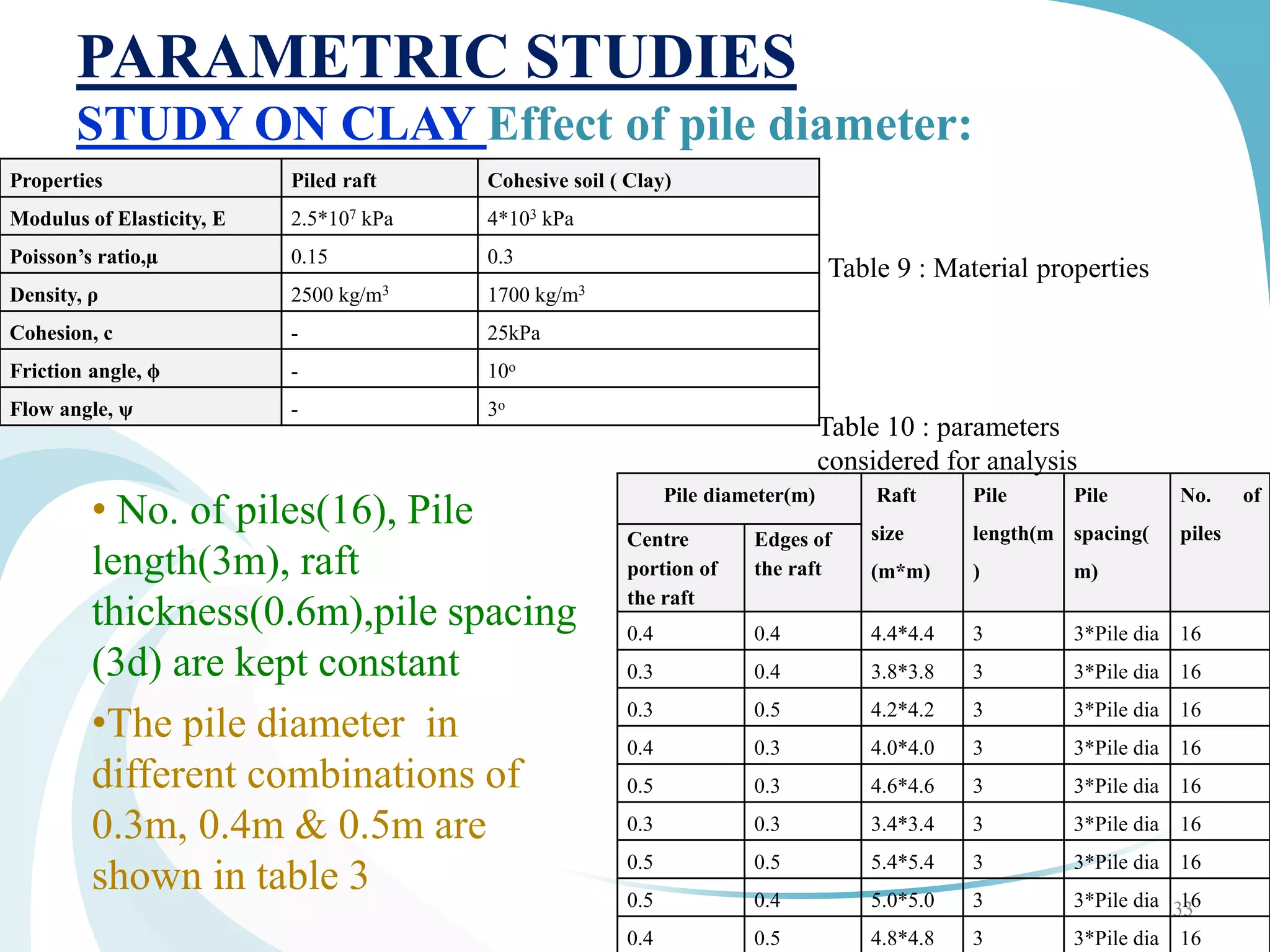
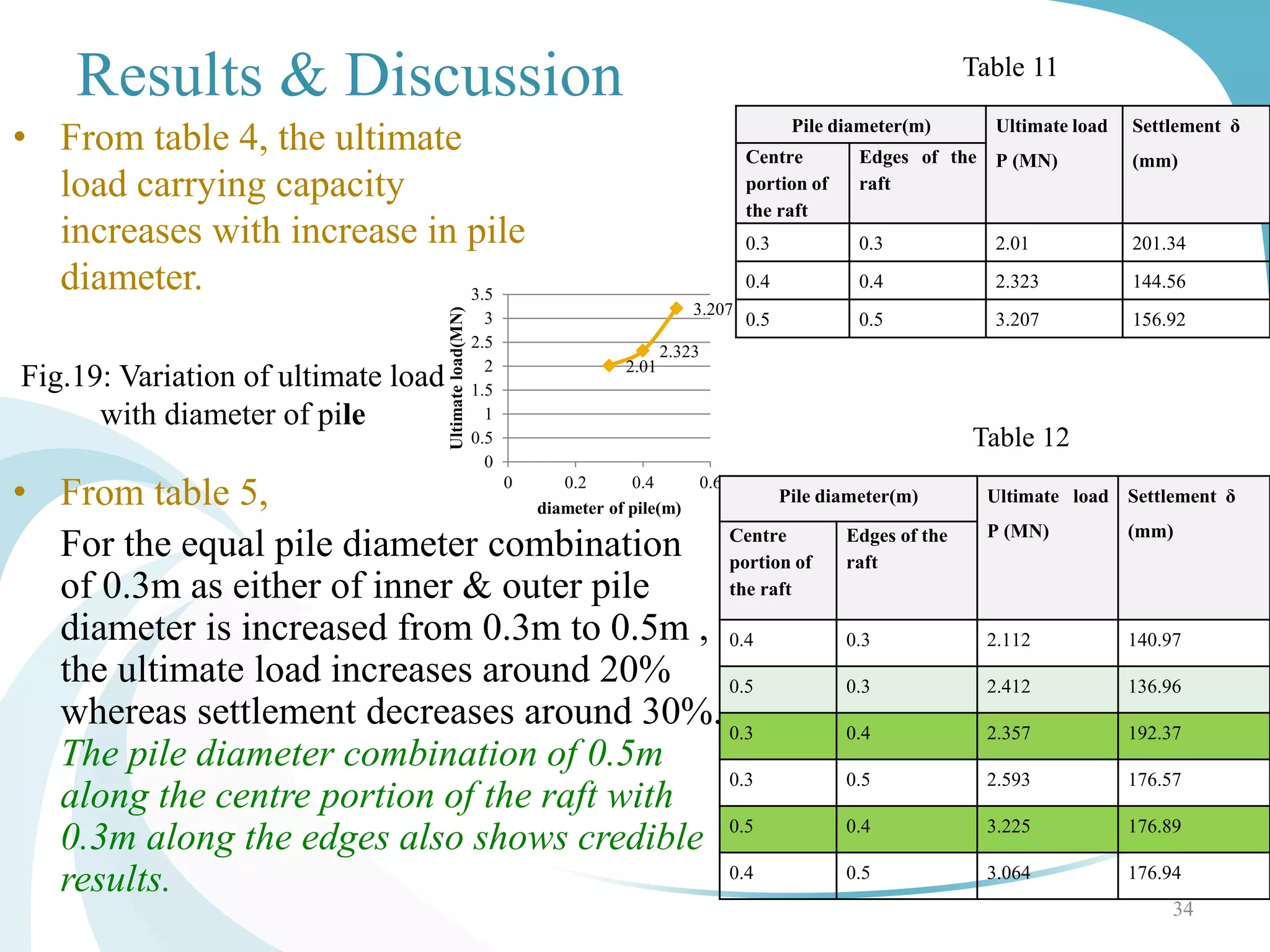
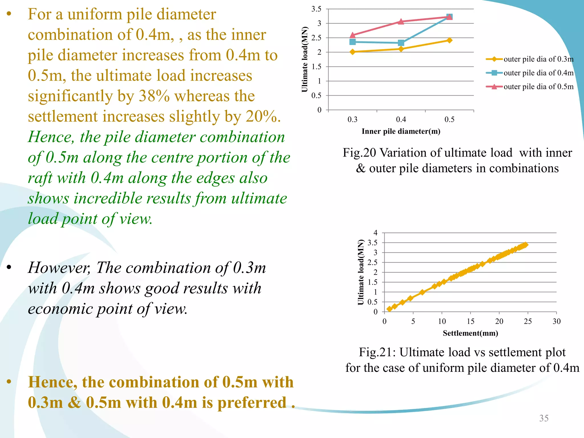
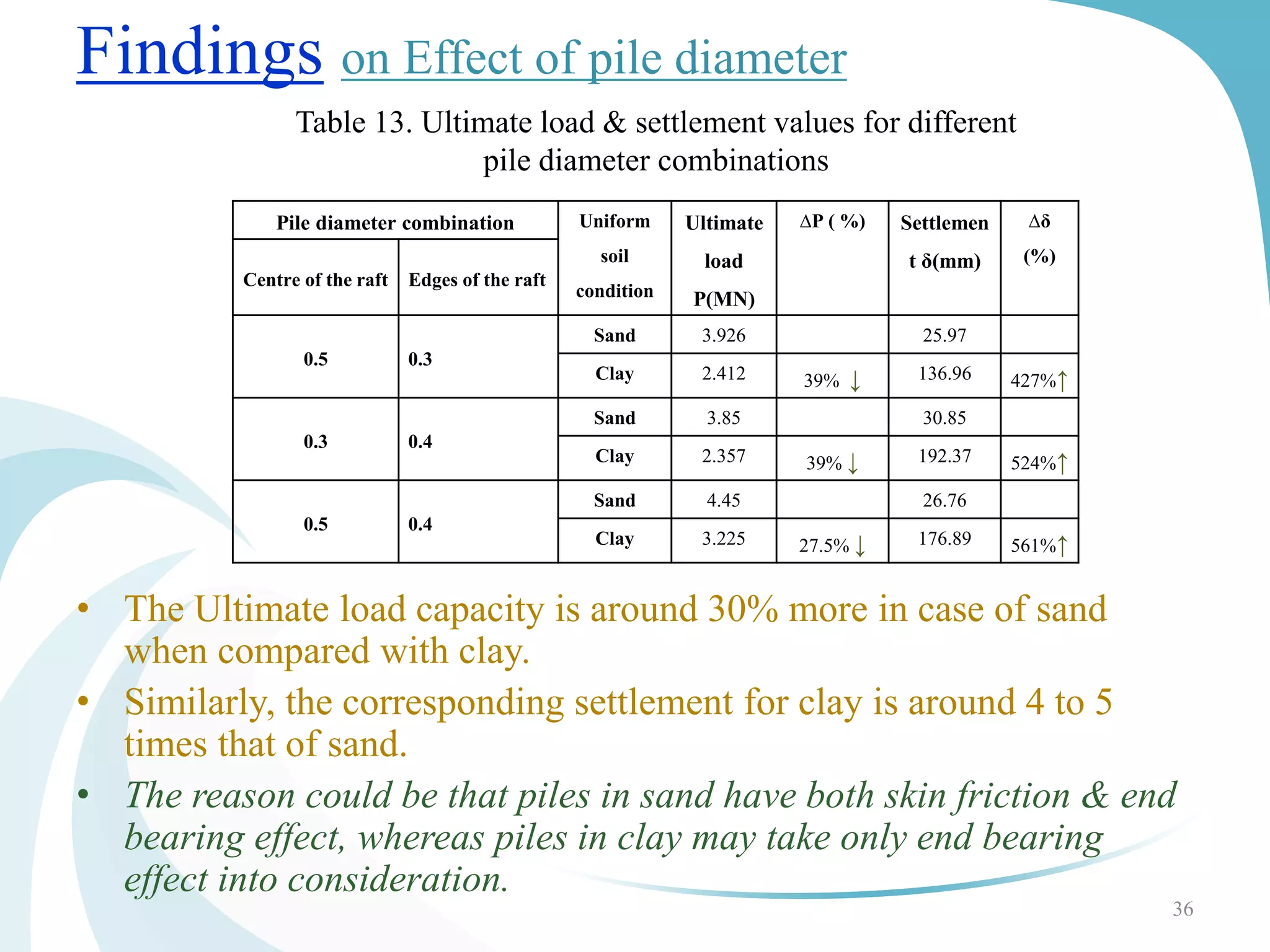
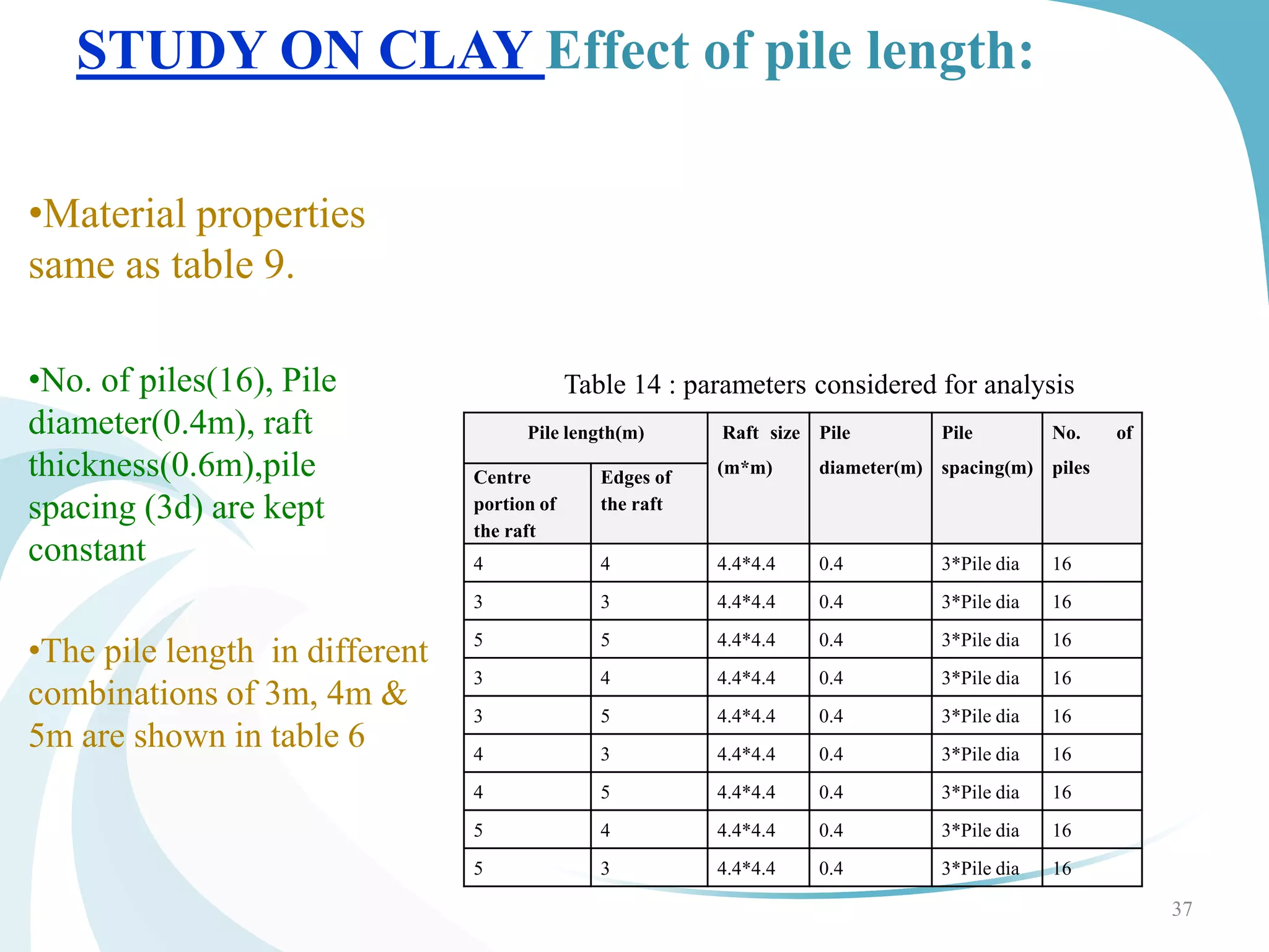
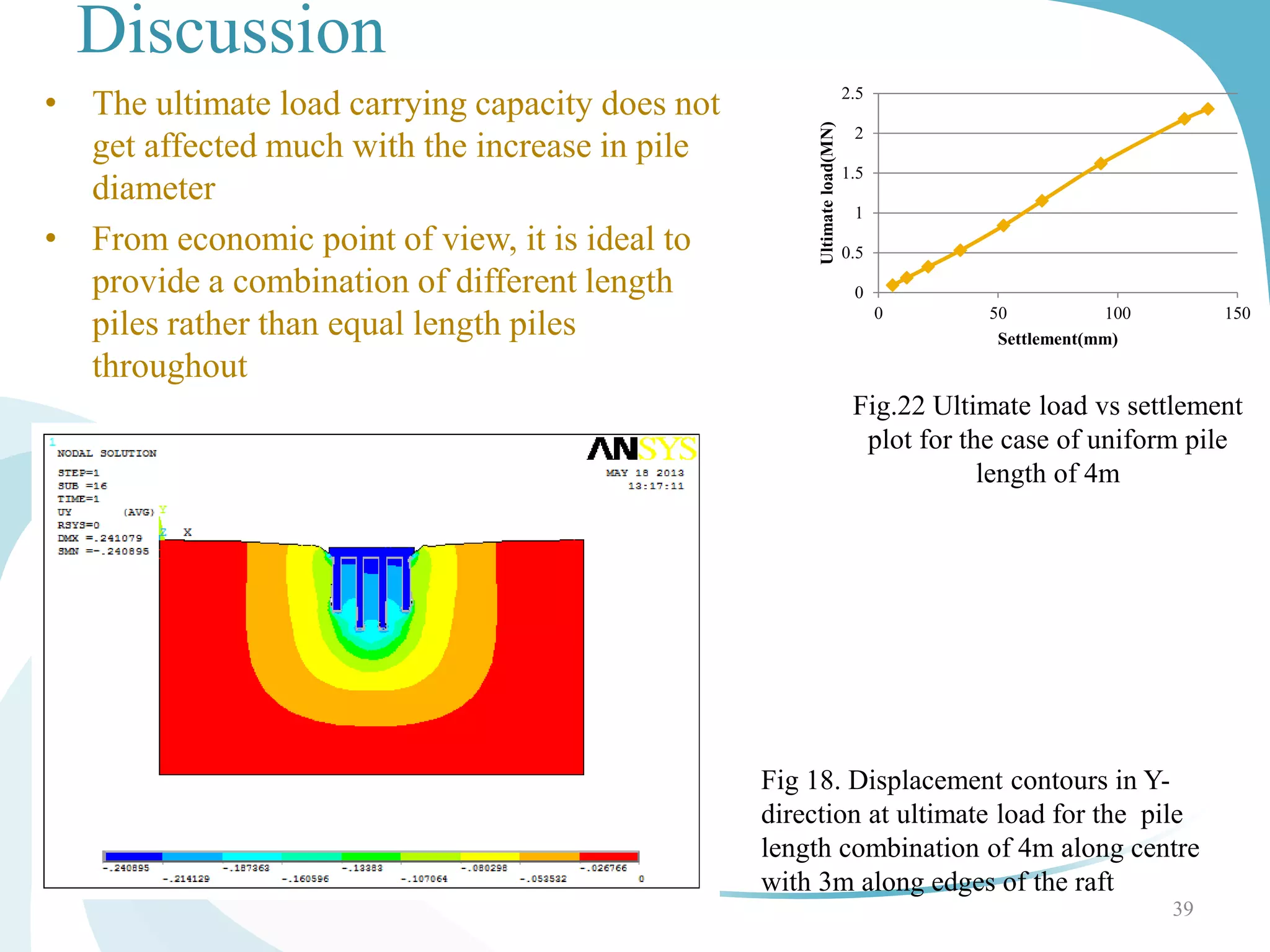
This document outlines a study on analyzing piled raft foundations using finite element analysis in ANSYS. It begins with an introduction to different types of foundations and focuses on piled raft foundations. The document discusses the methodology, which includes defining elements, material properties, meshing, boundary conditions, and nonlinear static analysis. It then validates the ANSYS model against theoretical calculations and literature findings. Finally, it presents parametric studies on the effects of pile diameter and length combinations on the ultimate load capacity and settlement of piled raft foundations in sand. The key findings are that using larger diameter piles in the center of the raft and smaller diameters at the edges provides higher load capacities with less settlement.

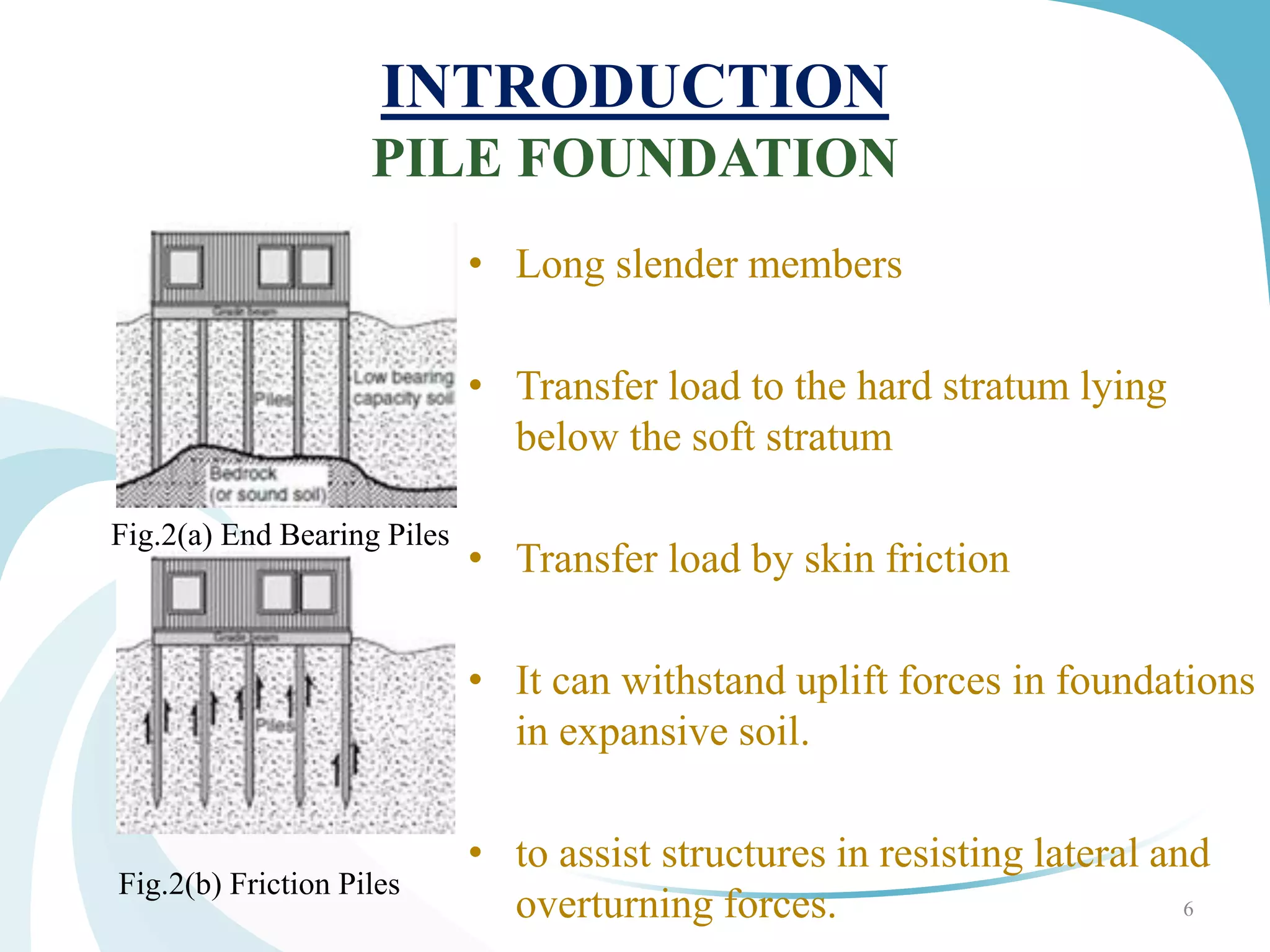
![LITERATURE STUDY
[3] Oh. et.al.(2008) FINITE ELEMENT MODELING OF PILED RAFT IN SAND
using PLAXIS.
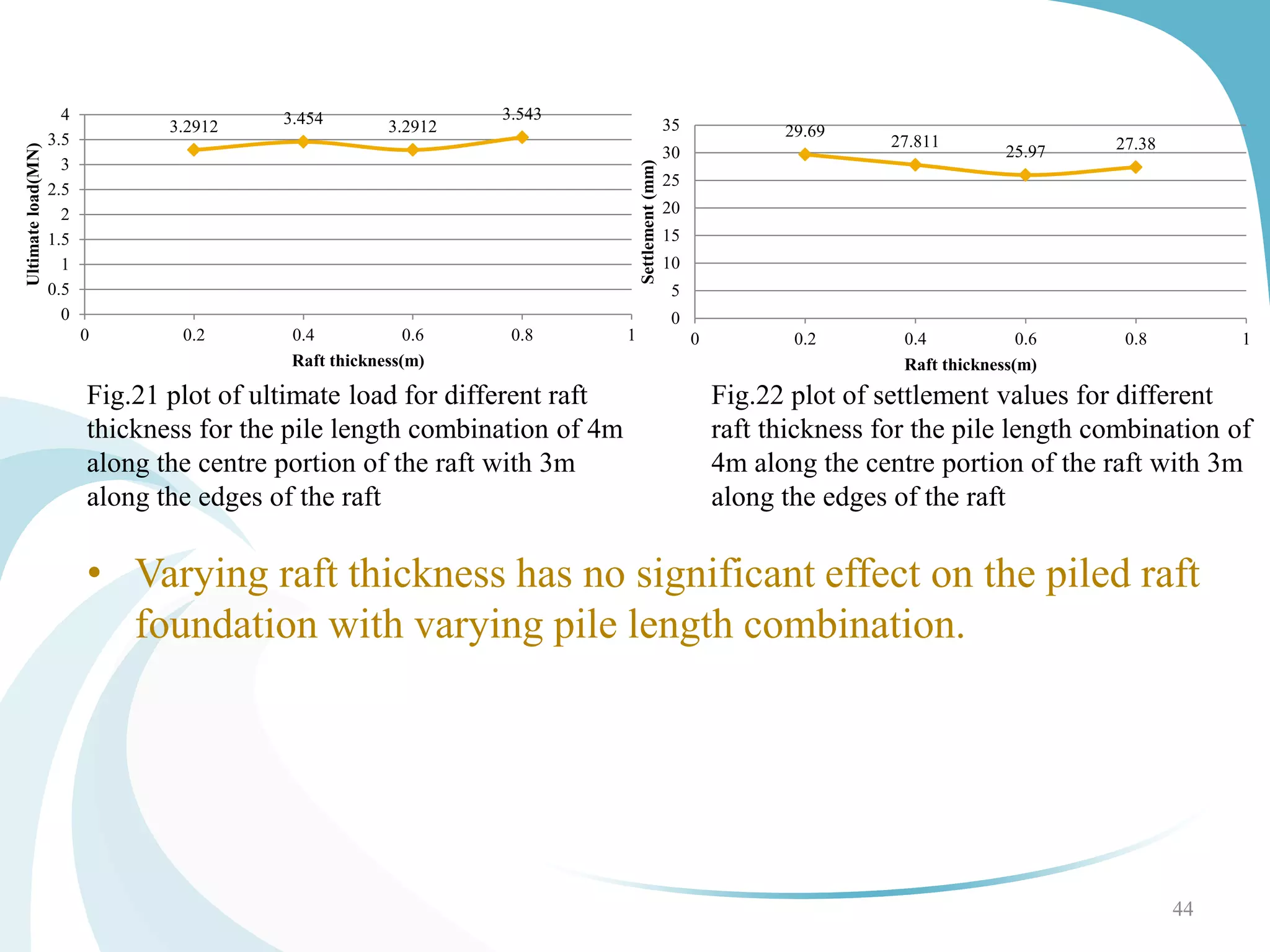
Raft thickness doesn’t affect the load carrying capacity of foundation
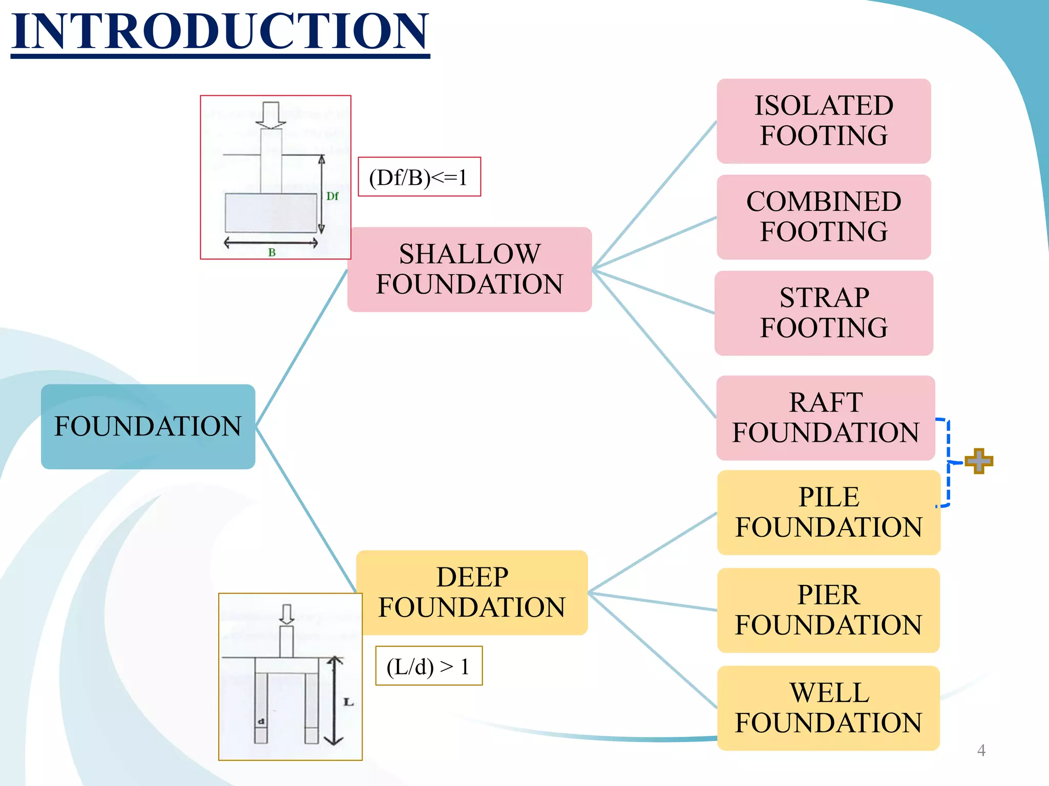
[17] Ningobham Thoiba Singh & Baleshwar Singh studied INTERACTION
ANALYSIS FOR PILED RAFTS IN COHESIVE SOILS (2008) using Ansys
Increase in raft thickness hasn’t improved the foundation behavior
greater raft thickness is not generally advantageous in reducing overall
or maximum settlement, provide optimum raft thickness
Addition of piles increases the load carrying capacity of a raft with
reduction in settlement.
Axial load is maximum at top portion of pile and is minimum at the tip.
[5] Srilakshmi & Chetan Gowda suggested that raft thickness does not have
influence on unifrom settlement & ultimate load capacity of foundatiom 14](https://image.slidesharecdn.com/33c5a03a-ceef-44ee-856a-b5c7a71e333c-160819021238/75/Mtech-Project_2013_ppt-14-2048.jpg)
![LITERATURE STUDY
Poulos et al.[7] Piled Raft Foundations for Tall
Buildings (2011) have used PLAXIS-3D to study
proposed piled raft foundation for INCHEON Tower at
S.Korea using the concept of Base embedment of Raft
with & without Soil for cases under horizontal &
vertical loading
• the bending down of rafts at corners and centre is
reduced in the case of basement wall embedment .
They have found out that Piled raft behaves
safely in high raised buildings when subjected to
horizontal & vertical loads.
15
Fig.6 Foundation layout
172 piles of 2.5m dia
lengths varying from
36m to 66m
Raft thickness of 5.5m
vertical basement of
the raft 14.6m(9.1+5.5)
below ground surface
level and 1.2m in
thickness
Fig.6](https://image.slidesharecdn.com/33c5a03a-ceef-44ee-856a-b5c7a71e333c-160819021238/75/Mtech-Project_2013_ppt-15-2048.jpg)
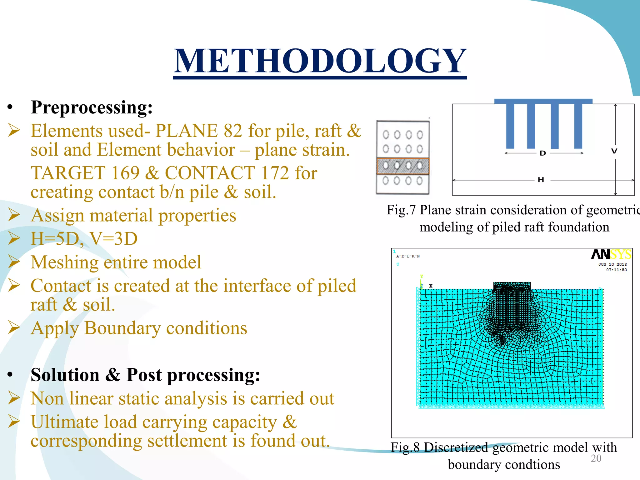
![VALIDATION OF ANSYS
VALIDATION 1 using formula
• Unpiled Raft foundation of size 5m×5m ×0.5m
[3,5,6,11,16,29,30,31]on a single layer soil.
The calculated settlement was 94.3mm.
22
Fig.9: Settlement contours for a
raft foundation
Here, from 2D
analysis, the
Settlement is found
out to be 95.4mm.](https://image.slidesharecdn.com/33c5a03a-ceef-44ee-856a-b5c7a71e333c-160819021238/75/Mtech-Project_2013_ppt-21-2048.jpg)
![24
Fig.11: Displacement contours along y-
direction
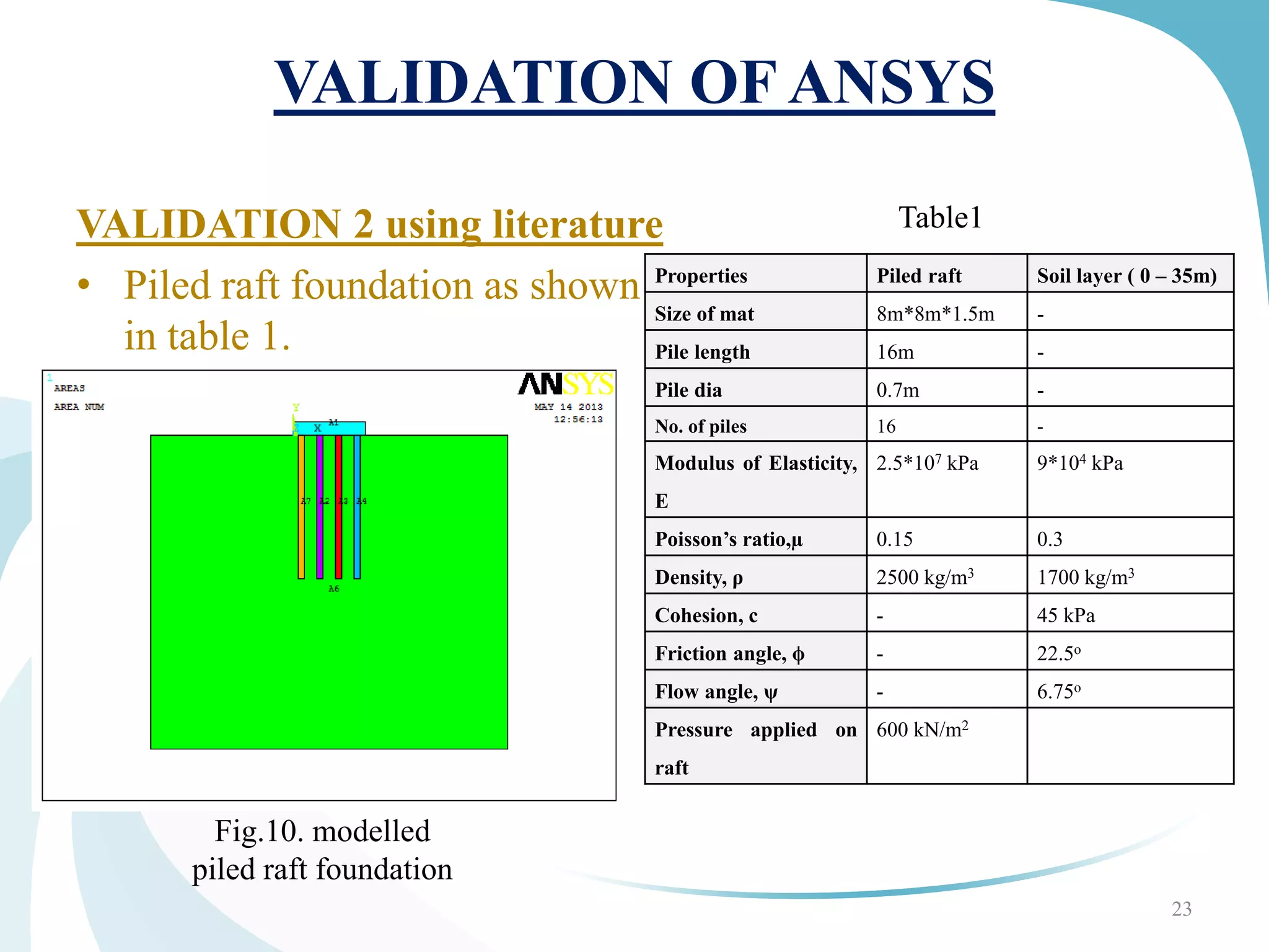
VALIDATION 2 using literature
From the literature[3], the
settlement was found out to be
64.3mm.
From ANSYS, the settlement
obtained was 69.414mm.
Hence, the results obtained from ANSYS are compatible with the
calculated theoretical results.](https://image.slidesharecdn.com/33c5a03a-ceef-44ee-856a-b5c7a71e333c-160819021238/75/Mtech-Project_2013_ppt-23-2048.jpg)


![Geotechnical Engineering-II [Lec #9+10: Westergaard Theory]](https://cdn.slidesharecdn.com/ss_thumbnails/9-181020124827-thumbnail.jpg?width=640&height=640&fit=bounds)


