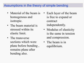
• Material ofthe beam is
homogenous and
isotropic.
• The beam material is
stressed within its
elastic limit.
• The transverse
sections which were
plane before bending ,
remains plane after
bending also.
• Each layer of the beam
is free to expand or
contract
independently.
• Modulus of elasticity
is the same in tension
and compression.
• The beam is in
equilibrium.
Assumptions in the theory of simple bending
4.
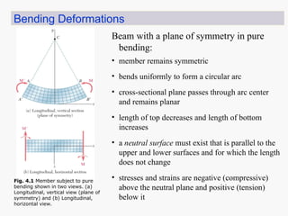
Bending Deformations
• bendsuniformly to form a circular arc
• cross-sectional plane passes through arc center
and remains planar
• length of top decreases and length of bottom
increases
• a neutral surface must exist that is parallel to the
upper and lower surfaces and for which the length
does not change
• stresses and strains are negative (compressive)
above the neutral plane and positive (tension)
below it
Beam with a plane of symmetry in pure
bending:
• member remains symmetric
Fig. 4.1 Member subject to pure
bending shown in two views. (a)
Longitudinal, vertical view (plane of
symmetry) and (b) Longitudinal,
horizontal view.
5.
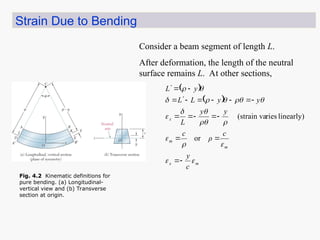
Strain Due toBending
Consider a beam segment of length L.
After deformation, the length of the neutral
surface remains L. At other sections,
m
x
m
m
x
c
y
c
ρ
c
y
y
L
y
y
L
L
y
L
or
linearly)
ries
(strain va
Fig. 4.2 Kinematic definitions for
pure bending. (a) Longitudinal-
vertical view and (b) Transverse
section at origin.
6.
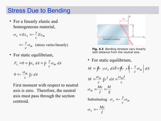
Stress Due toBending
• For a linearly elastic and
homogeneous material,
• For static equilibrium,
dA
y
c
dA
c
y
dA
F
m
m
x
x
0
0
First moment with respect to neutral
axis is zero. Therefore, the neutral
axis must pass through the section
centroid.
• For static equilibrium,
I
My
c
y
S
M
I
Mc
c
I
dA
y
c
M
dA
c
y
y
dA
y
M
x
m
x
m
m
m
m
x
ng
Substituti
2
linearly)
varies
(stress
m
m
x
x
c
y
E
c
y
E
Fig. 4.3 Bending stresses vary linearly
with distance from the neutral axis.
7.
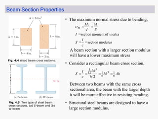
Beam Section Properties
•The maximum normal stress due to bending,
modulus
section
inertia
of
moment
section
c
I
S
I
S
M
I
Mc
m
A beam section with a larger section modulus
will have a lower maximum stress
• Consider a rectangular beam cross section,
Ah
bh
h
bh
c
I
S 6
1
3
6
1
3
12
1
2
Between two beams with the same cross
sectional area, the beam with the larger depth
h will be more effective in resisting bending.
• Structural steel beams are designed to have a
large section modulus.
Fig. 4.4 Wood beam cross sections.
Fig. 4.5 Two type of steel beam
cross sections. (a) S-beam and (b)
W-beam
8.
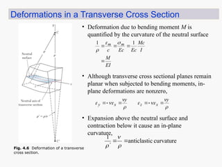
Deformations in aTransverse Cross Section
• Deformation due to bending moment M is
quantified by the curvature of the neutral surface
EI
M
I
Mc
Ec
Ec
c
m
m
1
1
• Although transverse cross sectional planes remain
planar when subjected to bending moments, in-
plane deformations are nonzero,
y
y
x
z
x
y
• Expansion above the neutral surface and
contraction below it cause an in-plane
curvature,
curvature
c
anticlasti
1
Fig. 4.6 Deformation of a transverse
cross section.
9.
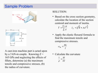
Sample Problem
SOLUTION:
• Basedon the cross section geometry,
calculate the location of the section
centroid and moment of inertia.
2
d
A
I
I
A
A
y
Y x
• Apply the elastic flexural formula to
find the maximum tensile and
compressive stresses.
I
Mc
m
• Calculate the curvature
EI
M
1
A cast-iron machine part is acted upon
by a 3 kN-m couple. Knowing E =
165 GPa and neglecting the effects of
fillets, determine (a) the maximum
tensile and compressive stresses, (b)
the radius of curvature.
10.
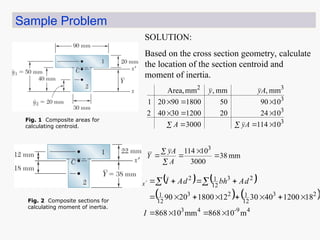
Sample Problem
SOLUTION:
Based onthe cross section geometry, calculate
the location of the section centroid and
moment of inertia.
mm
38
3000
10
114 3
A
A
y
Y
3
3
3
3
2
10
114
3000
10
4
2
20
1200
30
40
2
10
90
50
1800
90
20
1
mm
,
mm
,
mm
Area,
A
y
A
A
y
y
4
9
-
4
3
2
3
12
1
2
3
12
1
2
3
12
1
2
m
10
868
mm
10
868
18
1200
40
30
12
1800
20
90
I
d
A
bh
d
A
I
Ix
Fig. 1 Composite areas for
calculating centroid.
Fig. 2 Composite sections for
calculating moment of inertia.
11.
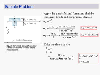
Sample Problem
• Applythe elastic flexural formula to find the
maximum tensile and compressive stresses.
4
9
4
9
m
10
868
m
038
.
0
m
kN
3
m
10
868
m
022
.
0
m
kN
3
I
c
M
I
c
M
I
Mc
B
B
A
A
m
MPa
0
.
76
A
MPa
3
.
131
B
• Calculate the curvature
4
9
-
m
10
868
GPa
165
m
kN
3
1
EI
M
m
7
.
47
m
10
95
.
20
1 1
-
3
Fig. 3 Deformed radius of curvature
is measured to the centroid of the
cross sections.