This document describes a new class of substituted cyclopentyl compounds useful for therapeutic purposes. Specifically, it describes cyclopentyl acetic acid amides containing substituents that are obtainable by condensing cyclopentyl acetic acid or derivatives with ammonia, amines or ureas. The document provides an example for synthesizing cyclopentyl-bromo-acetamide in three steps: 1) brominating cyclopentyl acetic acid, 2) converting it to the acetylchloride derivative, and 3) reacting it with aqueous ammonia. These compounds have sedative properties and can be used as intermediates for producing other therapeutic agents or used directly as therapeutics.
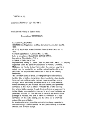
This document is a patent for a self-loading semiautomatic pistol filed by Marion W. Yale on February 3, 1950. It includes detailed diagrams and descriptions of the pistol's components and operating mechanisms. The pistol has an enclosed action with no outside moving parts except an operating rod. It is designed to be simple in construction, easy to dismantle and clean, and capable of being quickly reassembled to provide a well-balanced weapon.
1. A pistol includes a firing pin safety in the form of a resilient tongue attached to the breech part. The tongue has a hook that engages a shoulder on the striker when cocked. It also has a downward web that interacts with the trigger arm.
2. When the trigger is pulled, the trigger arm moves longitudinally and its finger pushes the resilient tongue's web outward, disengaging the hook from the striker shoulder.
3. The resilient tongue is integrally formed with an ejector spring that acts on an ejector claw, providing a simple, combined spring mechanism.
This document describes a patent for a target firearm with a blowback breech bolt mechanism and safety latch. It consists of a frame with a barrel mounted at the front and a tubular receiver at the back. A recoil spring operated breech bolt moves between a forward firing position and rearward loading positions. A safety latch holds the breech bolt in the loading position, while a trigger actuated sear holds it in the cocked position. The design uses few parts and allows for quick reloading without manually opening the chamber.
This document describes patent GB785273 for a holder for electronic devices like thermionic valves that have projecting terminal prongs. The holder has insulating material with contacts mounted on it. Each contact has a terminal portion extending beyond the body of the holder and formed with an attaching portion at the outer end. The attaching portion includes a resilient reverse-bend end portion adapted to be inserted into apertures in a supporting panel to electrically connect to circuits on the panel. The holder allows for easy assembly and connection of electronic devices to circuits printed on a supporting panel.
This document provides a 3-sentence summary of GB784603 (A) which describes a fuel feeding apparatus for pressure burners. The apparatus includes a valve body with passages that selectively connect a mixture tube, air passage, and fuel passages. A stationary rubber disk member and rotatable disk valve member control the connections between passages for starting, running, and shutting off the burner. The valve members and passages allow the burner to be supplied with an air-fuel mixture for starting and then operated with vaporized liquid fuel from the fuel tank.
This document describes a patent application for improvements to a rotary electric switch. Specifically, it describes a switch housing with fixed contacts on inclined surfaces connected by steps, and a rotary contact member that can complete electrical circuits by engaging the fixed contacts. Narrow grooves between the fixed contacts help extinguish any arcs that form when the circuit is opened to improve the switch's electrical rating and lifespan. The housing design allows for easy assembly of all switch components.
This document describes a patent for a composite refractory rail used in pusher-type furnaces. The rail is made of multiple sections with each section composed of a material suited to withstand the stresses of its corresponding temperature zone in the furnace. This eliminates the need for water cooling inside the furnace. Preferably there are three sections: steel up to 600°C, silicon carbide from 600°C to 900°C, and fused metal oxides above 900°C. The rail allows withstanding high temperatures and fluctuations without losses from water cooling.
This document describes improvements to magnetic separators and radial flow compressors. It discusses magnetic separator filter elements with slots and walls extending perpendicular from the slots. It also discusses a method of manufacturing radial flow compressors with different characteristics by using interchangeable rotor and insertion sets, including open and closed rotor types.
This document describes improvements to self-supporting containers made of carbon or graphite. It discusses how prior containers used ceramic linings that had poor thermal conductivity. The new containers described are built from interlocking carbon or graphite plates that form a self-supporting inner structure. This allows the container to be spaced within an outer metal or concrete vessel, improving heat transfer and accommodating different expansion rates of the materials. Diagrams show how the plates interlock at joints and are held together with cement.
This document describes improvements to ventilators and provides details of GB785218(A). It contains the following key information:
1) GB785218(A) relates to a ventilator with one or more groups of parallel pivoted louvres that are connected for parallel movement. The louvres are arcuate in cross-section and rotate to open and close the ventilator.
2) Each louvre is mounted on a pivot rod and connected to a control linkwork so that all louvres in a group rotate through the same angle simultaneously. This provides smooth air flow and directs air flow when open.
3) The ventilator can be made weather
[Writing Sample] USPTO Office Action Response by Bryan Johnsonimpekable
This document contains amendments to a patent application for a muffler pipe storage rack. It includes amendments to 15 paragraphs of the specification to clarify descriptions of the rack and its dimensions. It also includes amendments to 14 claims, clarifying language around dimensions of slots and clearances for accommodating muffler pipes of various sizes. One claim is withdrawn.
This document describes a patent for an earth-leakage indicating device. It consists of three star-connected sliding contact resistances that create an artificial neutral point. Voltages from each resistance charge a condenser through rectifiers, providing a direct current. If an insulation failure occurs, this direct current passes through an ohmmeter, allowing the degree of insulation to be determined based on the ohmmeter reading. The device is connected to a three-phase power network through fuses and a push button, and operates by detecting fault currents to earth.
This document describes a patent for improvements to transformers. It discusses how distribution transformers need to withstand short circuits of currents 25-40 times the rated current without the coils moving relative to each other. This can cause insulation breakdown over time. The invention aims to provide an improved arrangement for anchoring the transformer coils to prevent relative movement when subjected to powerful electromagnetic forces from short circuits many times the rated capacity.
The document describes two embodiments of a mechanical gland seal for preventing liquid leakage along rotor shafts of rotary pumps. The first embodiment uses a spring bellows to apply pressure to a carbon ring, sealing it against the shaft flange. An O-ring additionally seals the interior from the exterior of the housing. The second embodiment uses a spring-loaded header ring compressing an H-section seal between the header and a carrier holding the carbon ring, sealing both the interior and along the shaft flange.
This document describes improvements to a fluid mixing device that maintains the temperature of a fluid mixture. The device comprises an adjustable valve with a hollow liner and rotatable sleeve that have radial ports to supply and mix two fluid streams. The sleeve is rotated by a thermally sensitive unit to control the proportions of the streams and maintain the mixture at a predetermined temperature. The valve can be dismantled without damaging the unit and ensures correct reassembly. The device provides close temperature control even at low flow rates in an economical and compact design.
This document describes a spray booth patent from 1957. Key features include:
1) The spray booth uses exhausted ventilation air to pneumatically convey water droplets from the bottom basin to retainers in an exhaust duct above overflow devices, allowing the water to flow back by gravity.
2) This eliminates the need for a circulation pump and reduces clogging from paint in the water compared to pump circulation.
3) The spray booth operates by exhausting air through the operating chamber, which pulls water droplets up from the bottom basin to collectors above before exiting through the exhaust duct.
This patent document describes improvements to bolting means where one side of a joint is inaccessible during assembly. It involves using setscrews with eccentric heads that can be inserted into holes and rotated so the heads are trapped in grooves, preventing withdrawal from the holes. Nuts are then tightened on the setscrews to clamp parts together at the joint. The invention avoids using studs and reduces weight and manufacturing costs compared to prior bolting methods for inaccessible joints.
This document describes two British patents from 1957:
1) GB784929(A) describes aircraft doors for a bomb bay that open by sliding up the outside of the aircraft rather than swinging downward to reduce drag.
2) GB784930(A) describes a movable platform in an aircraft bomb bay that can lower a bomb/missile below the bay opening while largely closing the opening to further reduce drag when bombing. The platform is operated by lever arms connected to jacks.
This document describes patent GB785178 (A) relating to improvements in steam irons. It includes a U-shaped heating element with a flash boiler adjacent to one limb. Steam ports extend through the sole plate and a steam passage leads from the boiler alongside the heating element to superheat the steam before it exits the ports. The steam is generated in a zone of concentrated heat near the boiler and heating element and passes through the long steam passage where it remains in contact with the heating element to be fully superheated before exiting.
1) The document describes a split metal sleeve for protecting drill pipes during oil drilling.
2) The sleeve consists of two resilient metal segments that interlock at side edges to form a continuous circumference when installed on the drill pipe.
3) The segments are curved more than 180 degrees so they must be sprung over the pipe diameter, and their interlocking edges ensure a tight, secure fit that can withstand stresses during drilling.
This document describes patent GB786114 (A) for a split metal sleeve. It involves:
1) Providing a length of metallic tubing with an inner radius smaller than the object it will embrace.
2) Heat treating the tubing to make it resilient.
3) Flame-cutting the tubing into two segments with interlocking side edges that have a total arc length exceeding 180 degrees.
This document describes British patent GB785368 (A) filed in 1957 regarding improvements to metal structures. It involves a framework of tubular members interconnected by junction members that fit into the bores of the tubular members. Sheet metal forms the skin of the structure. The framework comprises spaced horizontal and inclined tubular members joined by T-shaped, cruciform, and other specially shaped junction members. At assembly, sheet metal panelling is applied and secured to the frame with bolts or rivets to lock the joints. This allows for simple, inexpensive and readily assemblable metal framed structures like portable buildings.
This document describes a new class of organic compounds called diamines and their salts. It defines the general chemical formula for these compounds and describes methods for synthesizing them, including forming Schiff bases and then reducing the Schiff bases. It provides three examples of synthesizing specific diamines by reacting an aldehyde with a primary amine to form a Schiff base, then reducing the Schiff base over a catalyst. The resulting diamines are then converted to salts by reaction with acids. The diamines produced in this way are described as being useful intermediates for producing substances with therapeutic activity.
This document describes a patent application filed by Allen & Hanburys Limited for new diamine compounds and salts thereof. The compounds have a general formula shown, where a, b, and c can be integers from 1 to 3, and R is hydrogen or an alkyl group. The compounds are described as new organic bases that may have pharmaceutical applications.
This document describes a water softening device that uses ion exchange to soften water from mains before it reaches domestic or industrial premises. It contains a cartridge holding the ion exchange medium that is detachably mounted to a frame. The frame can be fixed to a wall. Water enters the bottom of the cartridge, passes through the ion exchange medium, and exits the top, now softened. The cartridge design makes the water softener inexpensive enough to use with water heaters.
This document describes British patent GB780011 (A) for improvements to water softening devices. Specifically, it describes a water softening device that uses a cation exchange process and incorporates a cartridge containing the softening medium. The cartridge is detachably mounted to a frame-like structure that can be fixed to a wall. The device is designed to be lower cost than previous water softening equipment in order to be used in conjunction with water heaters.
El documento describe la gerencia de proyectos y el ciclo de vida de un proyecto. Explica que la gerencia de proyectos implica organizar y administrar recursos como tiempo, dinero y personal para garantizar que un proyecto se complete dentro del alcance, tiempo y costo planificados. También define el ciclo de vida de un proyecto como las fases que conectan el inicio y fin de un proyecto, incluyendo fases inicial, intermedia y final. Finalmente, señala que la planificación estratégica es importante para garantizar un ciclo de vida
El documento habla sobre la gerencia de proyectos y el ciclo de vida de un proyecto. Explica que la gerencia de proyectos se encarga de sugerir áreas de necesidad, planificar estratégicamente y garantizar el ciclo de vida de un proyecto para conectar la visión del proyecto con el futuro. También describe que el ciclo de vida de un proyecto define las fases que van desde el inicio hasta el fin de un proyecto, incluyendo fases inicial, intermedia y final.
El documento describe el ciclo de vida de los proyectos y el rol del gestor del proyecto. El ciclo de vida de un proyecto incluye tres fases: la fase inicial de estudios y análisis, la fase intermedia de implementación de la solución, y la fase final de generación del producto o servicio. El gestor del proyecto debe poseer habilidades como la detección de asunciones, resolución de conflictos, reconocimiento y mitigación de riesgos, y comunicación abierta. Los interesados en el proyecto
La situación actual en varias áreas como reuniones, proyectos, acceso a expertos, cultivo de comunidad y participación individual está por debajo del nivel deseado. Se necesita mejorar el acceso a expertos, los proyectos en curso, y aumentar la participación individual y comunitaria para alcanzar los objetivos deseados.
This short document contains a link and encourages the reader to click on it to access some unspecified content or offer. No other context or details are provided about what would be obtained by clicking the link.
The Quattrocento was an important period in 15th century European art, known as the early Renaissance. Centered in Florence under the patronage of the Medici family, art of this era focused on accurately depicting the human figure and applying techniques like perspective. Sculptors like Donatello and Ghiberti represented the human body realistically, while painters such as Masaccio, Botticelli, and Piero della Francesca applied perspective to their paintings. Architects including Brunelleschi and Alberti introduced simple design elements to better define space in their buildings.
La marca personal describe el proceso por el cual individuos y empresarios se diferencian y destacan entre una multitud, identificando y expresando su propuesta de valor único, ya sea profesional o personal que después promocionan en distintas plataformas, con un mensaje y una imagen consistentes que les permita alcanzar una meta específica. De este modo, los individuos pueden conseguir que se los reconozca cada vez más como expertos en su terreno, labrarse una reputación y credibilidad, fomentar su carrera y mejorar la confianza en sí mismos.
Casi de la noche a la mañana, la revolución digital le ha dado la vuelta a las leyes sobre las marcas. Lo que importa ahora no es el tamaño, sino la actitud: flexible, ágil, transparente en su actuación, global en su perspectiva.
El documento analiza las proyecciones de crecimiento de la población mundial realizadas por la ONU. Se prevé que la población alcance los 9,000 millones en 2050 y posiblemente los 16,600 millones hacia el 2100, concentrado principalmente en países en desarrollo de África y Asia. Adicionalmente, se espera que la proporción de personas mayores de 60 años aumente del 23% actual al 32% en 2050, debido al envejecimiento de la población.
Having confidence in one's own abilities is important. Self-belief helps people achieve their goals and dreams. With self-belief, one feels empowered to take on challenges and overcome obstacles.
1. This document describes a method for insulating individual sector-shaped conductors using an extrusion process to form multi-core cables.
2. The key steps of the method include twisting the conductor, feeding it non-rotatably through a rotatable guide with a matching outlet shape, which causes the guide to rotate in sync with the conductor lay, and finally feeding the conductor through a coupled die head where plastic insulation is applied.
3. The guide and die are driven together in rotation to maintain the proper orientation between the conductor's cross-sectional shape and the guide outlet as the conductor passes through.
1. This document describes a method for insulating individual sector-shaped conductors using an extrusion process to form multi-core cables.
2. The key steps are twisting the conductor, feeding it non-rotatably through a rotatable guide conforming to the conductor's shape, which causes the guide to rotate, and finally feeding the conductor through a coupled die head where plastic insulation is applied.
3. The guide and die rotate together in synchronization with the spiral lay of the pre-twisted conductor to properly orient the conductor's cross-sectional shape.
This document describes a patent for improvements to food mixers. It discloses a mixer with an elongated spinner shaft that carries a spinner on one end and connects detachably to the power take-off of the mixer on the other end. A stationary guide receives and steadies the spinner shaft near the spinner to prevent whipping. The spinner shaft connects to the power take-off shaft through a longitudinally movable connector urged away by a spring to form a combined journal and thrust bearing and running seal.
This document describes a patent for a method of conditioning web-like materials in a closed chamber using a gaseous medium containing water vapor. The method involves dividing the conditioning process into separate treatment steps where the material is cooled between steps. The relative humidity is successively increased in each step. This allows for more even moisture distribution compared to previous single-step methods. Diagrams and figures show the multi-step apparatus used to perform this conditioning process.
This patent document describes a mechanism for producing and securing a tear strip to packaging. It involves cutting a narrow strip from the end of a wide band, using suction to hold the strip, and pressing it against the packaging while heating to seal it in place. The mechanism aims to provide a simpler alternative to existing methods that use narrow tape reels.
This document summarizes British patent GB785929 (A) which relates to improvements in fabric tentering and drying machines. Specifically, it describes a machine that has upper and lower nozzle boxes for blowing heated air onto a fabric web to dry it. The machine features filters with automatic cleaning means to remove dust and fibers. It also allows the upper nozzle box and nozzles to be hinged upward along with a lid, providing easy access for examination, repairs and cleaning of the machine parts.
This document describes a patent for an automatic control system for a vehicle's variable-speed transmission mechanism. The system uses electromagnets to actuate the gear-changing components and relays to control the electromagnets. A moving coil actuates switches that control the relays based on vehicle speed. As speed increases, it causes the gears to change automatically from first to second to third. This allows for fully automatic shifting of the vehicle's transmission based on speed.
This document summarizes a patent for testing compressors, particularly refrigerant compressors. It describes a new testing method and apparatus that can quickly and accurately test compressors. The key aspects are:
1) It measures the time required for a compressor to build up a predetermined discharge pressure against a fixed restrictor, rather than maximum pressure, providing a faster and more accurate measurement.
2) The apparatus includes a fixed restrictor connected to the compressor discharge, a pressure switch, and a solenoid valve.
3) During a test, the compressor initially operates unrestricted to build pressure, then the valve closes and timing begins when a predetermined pressure is reached, providing a quick measurement of compressor performance.
This document describes an apparatus for extracting air from fiber suspensions used in papermaking. It discusses how air in fiber suspensions can cause issues in paper quality and discusses prior methods for air extraction. The invention aims to improve prior methods by including a vacuum chamber and means for vibrating the fiber suspension within the chamber to facilitate separation of air bubbles from the fibers. It provides various examples of configurations for the vibrating means and discusses how the invention allows for highly effective air removal from fiber suspensions.
This document describes a self-loading transport vehicle. It includes a shovel and trough that are pivoted to crowd material into the transport body. A dump gate at the bottom of the body opens and closes through connection to power means used to manipulate the shovel and trough. When the trough is moved toward its loading position, it causes the dump gate to close through this connection, with the gate held shut by a latch. The transport allows material to be loaded through use of the shovel and trough weights during opening and closing of the dump gate.
This document describes a mounting arrangement for an axial flow fan. It discloses a fan mounting that includes a plurality of curved arms to mount the fan to a structure defining a circular passage. The mounting arrangement is designed to improve acoustic noise performance and minimize packaging while maintaining efficiency. The document provides details of the fan design, including its hub, blades, and electric motor connection. It also references other prior art fan mounting arrangements.
The document describes improvements to ventilators provided with caps or covers. It discusses prior art issues with accessing motors for inspection and repair when the fan is located down the ventilator or with large access doors. The invention addresses this by arranging the fan and motor in the upper, conical part of the ventilator under the cap. This allows the cap to be displaced to provide top access to the motor without needing to be hinged or counterweighted, which would increase the cap's weight significantly. The objective is to enable easy displacement of the cap to access the motor from the top without additional heavy components.
This document describes a starting switch for internal combustion engines comprising electrical contacts in a housing and a rotor mounted in the housing. The rotor is operatively connected to an actuating shaft to close the contacts. A suction responsive ball is adapted to move to an effective position by engine suction to block rotation of the rotor and prevent closing of the contacts after the engine starts. The starting switch utilizes a spherical suction responsive member and provides initial positive actuation of the member to keep it from sticking, making the switch self-cleaning and unaffected by dirt or impurities.
This document describes a patent for an electric starting switch for internal combustion engines. The starting switch uses a rotor mounted in a housing connected to the throttle shaft. A suction-responsive ball is moved into position by engine vacuum to prevent the rotor from closing the electrical contacts and energizing the starting motor after the engine starts. The relatively compact design uses a minimum number of parts and a self-cleaning ball to remain unaffected by dirt or impurities.
This document describes improvements to control means for electric current converters. It discusses providing control of discharge paths through respective control electrodes over a wide range, from rectifier to inverter operation. Each control electrode is connected to two inductive members (transformers or chokes) supplied with phase-displaced operating currents/voltages from AC busbars. There are means for imparting a commonly variable direct current premagnetization and means for imparting independently pre-settable direct current premagnetizations, allowing control of each electrode's feed to provide a control voltage during a portion of the converter's total control range.
This document describes a steam trap patent from 1957. The steam trap uses a rotary member controlled by a bimetallic strip to vary the size of the discharge opening and allow condensate to drain while preventing steam from escaping. It provides a constantly open minimum opening, and the bimetallic strip automatically enlarges the opening when more condensate is present, such as during startup. The rotary member design allows for rapid response to temperature changes and a compact design that can be installed directly in a pipe line.
This document summarizes a patent for a machine that applies rubber caps to containers. It describes a machine with fingers arranged in an annular form that can place a cap, and pistons that impart radial movement to the fingers. It also includes a rotary table to carry containers, a head carrying the fingers that can slide, and a piston to actuate the head. The machine applies caps by extending the fingers to stretch the cap over the container, then retracting the fingers to leave the cap in place.
This document describes a fire extinguisher comprising a flat circular tank containing liquid and a foaming agent cartridge. It has a central discharge nozzle and a rotatable tubular arm that can cut through the cartridge to mix the foaming agent into the liquid. The arm is connected to the nozzle and has branches that ensure the mixture can be discharged regardless of the extinguisher's orientation. Rotation of a handle slides the nozzle and arm, breaking a seal and allowing the arm to cut the cartridge and discharge the foaming mixture through the nozzle.
This document summarizes a patent for manufacturing oximes of cycloaliphatic ketones. It describes a process where salts of thiosulphuric acid or polythionic acids are used as reducing agents in aqueous solution to produce oximes from water-soluble salts of secondary nitro-compounds in the cycloaliphatic series. The ratio used is 1 mole of nitro-compound to 1-1.5 moles of reducing agent salt. Examples provided demonstrate producing cyclohexanone oxime from nitrocyclohexane using sodium thiosulphate or sodium trithionate as the reducing agent. Yields of up to 92% of the oxime product are achieved.
This document describes glyoxalidine corrosion inhibitors for use in hydrocarbon liquids like gasoline and diesel fuel. Specifically, it describes new chemical compounds that are salts of a glyoxalidine and an organic aliphatic dicarboxylic acid with at least 10 carbon atoms. These compounds are effective corrosion inhibitors for ferrous metals in contact with hydrocarbon liquids that contain small amounts of water. Test results show that reactions products of sebacic acid and certain glyoxalidines can inhibit corrosion in gasoline-water systems at low concentrations.
This document describes a patent for improvements in the production of the antibiotic griseofulvin under deep culture conditions. It finds that griseofulvin can be produced on a large scale through submerged aerobic culture of suitable organisms, such as Penicillium patulum, if the available nitrogen level in the culture medium is carefully controlled between 0.04-0.3% nitrogen. Optimum yields are obtained at nitrogen levels of 0.075-0.25%, with the specific optimum depending on factors like inoculum type and fermenter size.
The document describes new disazo dyes and copper complexes of those dyes. The dyes correspond to general formula 1, where R1 is the residue of an oxybenzene-ortho-carboxylic acid, R2 and R3 are benzene residues with the carbon atoms bound to the azo linkage and carboxamide group separated by at least one carbon atom, and R4 is a benzene residue containing a sulphonic acid, carboxylic acid, or carboxymethoxy group. The dyes can be prepared by coupling a diazo compound of an aminoazo dye with a phenylamino-8-oxynaphthalene compound. The resulting dyes and their copper complexes are
The document describes improvements to the "oxo process" for producing oxygenated organic compounds from olefins using carbon monoxide, hydrogen, and a carbonylation catalyst. Specifically, it involves using a catalyst combination that is particularly effective for catalyzing the reaction. The oxo process typically involves three stages - an initial reaction of the olefin with carbon monoxide and hydrogen over a cobalt catalyst to produce aldehydes, removal of soluble metal compounds from the product, and then hydrogenation of the aldehydes to alcohols. The invention relates to improving the catalyst used in the first stage of the reaction.
1) The document describes improvements to packaging containers that provide reinforcement and strength.
2) The containers have a non-metallic shell and bottom each with a corrosion-resistant thin inner lining that is partly inside and partly outside the container.
3) The shell has an outer reinforcing metal covering that is folded together with the outer parts of the linings to seal the container while keeping the bottom and shell unfolded.
This document summarizes a patent for recovering cooking liquor from spent soda pulping liquors. It describes how traditional soda pulping processes are expensive and wasteful due to the loss of sodium hydroxide in washings and stack gases. The invention provides a practical method for regenerating the soda with minimal loss, eliminating hazards and allowing recovery of soda cooking liquor from waste liquors containing it.
This document describes a multi-tray clarifier system for clarifying liquids containing suspended solids. The system uses multiple compartments and a central feedwell system to evenly distribute incoming feed between compartments. This even distribution allows for simplification of the clarifier design by reducing the number of intermediate compartments needed compared to previous clarifier designs.
The document describes improvements to a storage device for cylindrical objects like barrels. The storage device features an inclined rack with a gate at the lower end that retains the cylindrical objects. The gate has two angular portions - a first portion with an upstanding stop member, and a second portion that acts as a positive stop as long as an object is resting on the first portion. This allows objects to be released individually from the storage device when the gate is opened.
This document summarizes an invention for improvements in single-sideband radio transmission systems. It describes a system that uses band compression at the transmitter and band expansion at the receiver to transmit a single-sideband signal while reducing the required bandwidth. The system detects the signal envelope and uses it to amplitude modulate the compressed single-sideband signal before transmission. At the receiver, the system uses the detected envelope to reconstruct the original single-sideband signal from the received compressed signal. The document provides detailed descriptions and diagrams of transmitter and receiver embodiments.
This document summarizes a patent for an improved paper pattern that can be temporarily bonded to fabric. The pattern is made of thin, flexible paper with markings on top. The underside has a heat-sealable, lubricous resin that is non-adhesive at room temperature but becomes adhesive when heated. This allows the pattern to be temporarily bonded to fabric to facilitate needlework while maintaining lubricity for easy needle passage. The resin may be an ethylene polymer, vinyl chloride polymer, or other specified thermoplastic. Figures show applying multiple patterns to fabric with an iron, an enlarged cross-section, and joining cut fabric pieces with attached patterns.
This document describes improvements to gyroscope apparatus. It summarizes two different gyroscope designs that use air bearings to support a rotating gyroscope rotor. In the first design, the rotor is supported within a concentric casing on a spherical air bearing. The casing is driven by a tubular drive shaft connected to conventional bearings. In the second design, a wheel-shaped rotor is supported within a spherical casing on an air bearing. The casing is driven by electric motor integrated with the lower casing portion and supported by ball bearings. Both designs use pickoffs and electromagnetic means to apply torques to the rotor and counteract precession forces to keep the rotor axis aligned with the casing rotation axis.
This document describes improvements to telephone systems, specifically regarding private automatic branch exchanges (PABX) serving large numbers of subscribers across multiple locations. It details a system with a parent PABX connected via two-wire tie-lines to satellite automatic exchanges. The parent PABX operator can set up calls to subscribers on satellite exchanges and receive visual supervisory indications of call progress over the tie-lines. This is achieved through signals sent on a non-speaking conductor and distinctive signals involving potential reversals at the tie-line conductors.
This document describes a patent for improvements in reciprocating motors that are actuated by a fluid supplied at constant pressure. It involves a piston valve that moves alternately into two positions, connecting one side of the piston to the pressure fluid supply and the other side to exhaust. Plungers on each side of the piston can enter cylindrical spaces at the end of the piston's working stroke to build up pressure and cause the valve to switch positions for the return stroke. Optional features include non-return valves in ducts connecting the valve cavities to the spaces to control fluid flow. The invention is intended for hydraulic motors but not limited to that application or liquid as the working fluid.
This document provides details of GB784673 (A) and GB784674 (A), which are patent specifications for two inventions. GB784673 (A) describes a method of producing printed circuit master drawings by removing portions of a black layer on a board to define a circuit pattern. GB784674 (A) describes a mending plug for tubeless tires, specifically a hollow rubber cylindrical plug inserted into punctures using an insertion tool. The document outlines the techniques and provides figures to illustrate the methods.
This document describes a process for dyeing or printing textiles or foils made of cellulose esters or linear aromatic polyesters. Specifically, it involves using acid dyestuffs from the anthraquinone series that have a sulphonic acid group that can be split off by a reducing agent. This causes the dyestuff to become insoluble and bond to the textile or foil substrate. Examples are provided of dyeing various materials like polyester fibers, acetate rayon and cellulose triacetate fibers using different dyestuffs and reducing agents. The dyed materials exhibit good light and wash fastness according to the document.
This document describes a patent for articles made of boron nitride and refractory oxide. The articles have unexpected combinations of refractory properties that make them valuable for uses requiring novel property combinations. These properties include high temperature resistance without degradation, thermal shock resistance, strength at high and room temperatures, chemical inertness, oxidation resistance, and controllable density and hardness for different applications. The invention provides refractory bodies with optimized balances of key properties sought for different industrial uses.
The document describes improvements to velocity modulated discharge tubes. It includes an elongated evacuated envelope with an electron gun at one end and a collector electrode at the other end. Cavity resonator portions are disposed transversely between spaced metal tube sections to form gaps. Each resonator portion includes parallel disk-shaped metal end walls mounted on adjacent tube sections and extending outwardly, with a cylinder of insulating material sealed between the end walls.
This document describes British patent GB784713 (A) from 1957 regarding improvements to fire alarms for combustible materials. It involves using continuous detector tubes made of fusible or thermally plastic material arranged in the combustible material. If a fire causes the temperature to rise, it will melt or soften the tube and reduce pressure, triggering an alarm. The tubes can have a sinuous shape and there can be multiple tubes to help locate an incipient fire. The document also provides details on the diagram and functioning of the alarm system using these fusible detector tubes.
This document describes an improvement to devices that measure torsional forces or oscillations in rotating bodies. It aims to eliminate the use of slip rings, which introduce contact resistance issues. The device inductively couples a rotating bridge, mounted on the rotating body, to a stationary generator and amplifier using two pairs of coils. One coil of each pair rotates with the bridge while the other is stationary. This allows electrical connection without slip rings. The coils are arranged and spaced to maintain coupling during any relative movement from bearings.
Joker Wigs has been a one-stop-shop for hair products for over 26 years. We provide high-quality hair wigs, hair extensions, hair toppers, hair patch, and more for both men and women.
Gemma Wean- Nutritional solution for Artemiasmuskaan0008
GEMMA Wean is a high end larval co-feeding and weaning diet aimed at Artemia optimisation and is fortified with a high level of proteins and phospholipids. GEMMA Wean provides the early weaned juveniles with dedicated fish nutrition and is an ideal follow on from GEMMA Micro or Artemia.
GEMMA Wean has an optimised nutritional balance and physical quality so that it flows more freely and spreads readily on the water surface. The balance of phospholipid classes to- gether with the production technology based on a low temperature extrusion process improve the physical aspect of the pellets while still retaining the high phospholipid content.
GEMMA Wean is available in 0.1mm, 0.2mm and 0.3mm. There is also a 0.5mm micro-pellet, GEMMA Wean Diamond, which covers the early nursery stage from post-weaning to pre-growing.
Unlocking the Secrets to Safe Patient Handling.pdfLift Ability
Furthermore, the time constraints and workload in healthcare settings can make it challenging for caregivers to prioritise safe patient handling Australia practices, leading to shortcuts and increased risks.
Comprehensive Rainy Season Advisory: Safety and Preparedness Tips.pdfDr Rachana Gujar
The "Comprehensive Rainy Season Advisory: Safety and Preparedness Tips" offers essential guidance for navigating rainy weather conditions. It covers strategies for staying safe during storms, flood prevention measures, and advice on preparing for inclement weather. This advisory aims to ensure individuals are equipped with the knowledge and resources to handle the challenges of the rainy season effectively, emphasizing safety, preparedness, and resilience.
About this webinar: This talk will introduce what cancer rehabilitation is, where it fits into the cancer trajectory, and who can benefit from it. In addition, the current landscape of cancer rehabilitation in Canada will be discussed and the need for advocacy to increase access to this essential component of cancer care.
TEST BANK FOR Health Assessment in Nursing 7th Edition by Weber Chapters 1 - ...rightmanforbloodline
TEST BANK FOR Health Assessment in Nursing 7th Edition by Weber Chapters 1 - 34.
Healthy Eating Habits:
Understanding Nutrition Labels: Teaches how to read and interpret food labels, focusing on serving sizes, calorie intake, and nutrients to limit or include.
Tips for Healthy Eating: Offers practical advice such as incorporating a variety of foods, practicing moderation, staying hydrated, and eating mindfully.
Benefits of Regular Exercise:
Physical Benefits: Discusses how exercise aids in weight management, muscle and bone health, cardiovascular health, and flexibility.
Mental Benefits: Explains the psychological advantages, including stress reduction, improved mood, and better sleep.
Tips for Staying Active:
Encourages consistency, variety in exercises, setting realistic goals, and finding enjoyable activities to maintain motivation.
Maintaining a Balanced Lifestyle:
Integrating Nutrition and Exercise: Suggests meal planning and incorporating physical activity into daily routines.
Monitoring Progress: Recommends tracking food intake and exercise, regular health check-ups, and provides tips for achieving balance, such as getting sufficient sleep, managing stress, and staying socially active.
The best massage spa Ajman is Chandrima Spa Ajman, which was founded in 2023 and is exclusively for men 24 hours a day. As of right now, our parent firm has been providing massage services to over 50,000+ clients in Ajman for the past 10 years. It has about 8+ branches. This demonstrates that Chandrima Spa Ajman is among the most reasonably priced spas in Ajman and the ideal place to unwind and rejuvenate. We provide a wide range of Spa massage treatments, including Indian, Pakistani, Kerala, Malayali, and body-to-body massages. Numerous massage techniques are available, including deep tissue, Swedish, Thai, Russian, and hot stone massages. Our massage therapists produce genuinely unique treatments that generate a revitalized sense of inner serenely by fusing modern techniques, the cleanest natural substances, and traditional holistic therapists.
Let's Talk About It: Breast Cancer (What is Mindset and Does it Really Matter?)bkling
Your mindset is the way you make sense of the world around you. This lens influences the way you think, the way you feel, and how you might behave in certain situations. Let's talk about mindset myths that can get us into trouble and ways to cultivate a mindset to support your cancer survivorship in authentic ways. Let’s Talk About It!
2024 HIPAA Compliance Training Guide to the Compliance OfficersConference Panel
Join us for a comprehensive 90-minute lesson designed specifically for Compliance Officers and Practice/Business Managers. This 2024 HIPAA Training session will guide you through the critical steps needed to ensure your practice is fully prepared for upcoming audits. Key updates and significant changes under the Omnibus Rule will be covered, along with the latest applicable updates for 2024.
Key Areas Covered:
Texting and Email Communication: Understand the compliance requirements for electronic communication.
Encryption Standards: Learn what is necessary and what is overhyped.
Medical Messaging and Voice Data: Ensure secure handling of sensitive information.
IT Risk Factors: Identify and mitigate risks related to your IT infrastructure.
Why Attend:
Expert Instructor: Brian Tuttle, with over 20 years in Health IT and Compliance Consulting, brings invaluable experience and knowledge, including insights from over 1000 risk assessments and direct dealings with Office of Civil Rights HIPAA auditors.
Actionable Insights: Receive practical advice on preparing for audits and avoiding common mistakes.
Clarity on Compliance: Clear up misconceptions and understand the reality of HIPAA regulations.
Ensure your compliance strategy is up-to-date and effective. Enroll now and be prepared for the 2024 HIPAA audits.
Enroll Now to secure your spot in this crucial training session and ensure your HIPAA compliance is robust and audit-ready.
https://conferencepanel.com/conference/hipaa-training-for-the-compliance-officer-2024-updates
At Apollo Hospital, Lucknow, U.P., we provide specialized care for children experiencing dehydration and other symptoms. We also offer NICU & PICU Ambulance Facility Services. Consult our expert today for the best pediatric emergency care.
For More Details:
Map: https://cutt.ly/BwCeflYo
Name: Apollo Hospital
Address: Singar Nagar, LDA Colony, Lucknow, Uttar Pradesh 226012
Phone: 08429021957
Opening Hours: 24X7
Exploring the Benefits of Binaural Hearing: Why Two Hearing Aids Are Better T...Ear Solutions (ESPL)
Binaural hearing using two hearing aids instead of one offers numerous advantages, including improved sound localization, enhanced sound quality, better speech understanding in noise, reduced listening effort, and greater overall satisfaction. By leveraging the brain’s natural ability to process sound from both ears, binaural hearing aids provide a more balanced, clear, and comfortable hearing experience. If you or a loved one is considering hearing aids, consult with a hearing care professional at Ear Solutions hearing aid clinic in Mumbai to explore the benefits of binaural hearing and determine the best solution for your hearing needs. Embracing binaural hearing can lead to a richer, more engaging auditory experience and significantly improve your quality of life.
LGBTQ+ Adults: Unique Opportunities and Inclusive Approaches to CareVITASAuthor
This webinar helps clinicians understand the unique healthcare needs of the LGBTQ+ community, primarily in relation to end-of-life care. Topics include social and cultural background and challenges, healthcare disparities, advanced care planning, and strategies for reaching the community and improving quality of care.
International Cancer Survivors Day is celebrated during June, placing the spotlight not only on cancer survivors, but also their caregivers.
CANSA has compiled a list of tips and guidelines of support:
https://cansa.org.za/who-cares-for-cancer-patients-caregivers/
CANSA support - Caring for Cancer Patients' Caregivers
5726 5730.output
1. * GB786134 (A)
Description: GB786134 (A) ? 1957-11-13
Improvements relating to clothes driers
Description of GB786134 (A)
PATENT SPECIFICATION
7869134 Date of Application and filing Complete Specification: Jan 10,
1956.
of 078 j/ Application made in United States of America on Jan 14,
1955.
Complete Specification Published: Nov 13, 1957.
Index at acceptance:-Class 34 ( 2), Q( 1 K:2 C 11 B).
International Classification:-F 26 b.
COMPLETE SPECIFICATION
Improvements relating to Clothes Driers We, HOOVER LIMITED, a Company
registered under the Laws of Great Britain, of Perivale, Greenford,
Middlesex, do hereby declare the invention, for which we pray that a
patent may be granted to us, and the method by which it is to be
performed, to be particularly described in and by the following
statement:-
This invention relates to driers According to the present invention a
tumbler drier for clothes comprising a drum mounted to rotate about a
horizontal axis within an outer casing is characterised by a turbine
arranged within the casing to receive a flow of air under pressure
from a remote source, for instance, a suction cleaner, and operatively
connected to the drum to rotate it Preferably the air after passing
the turbine blades passes through the drum In one arrangement the
turbine blades are mounted on the drum, in which case the blades are
preferably mounted on one end wall of the drum and an annular air
passage is included, one end of which is connected to a pipe
connection on the outer casing, and the other end of which lies
adjacent the turbine blades.
In an alternative arrangement the turbine is operatively connected to
the drum through a reduction drive The reduction drive may include one
or more pairs of friction pulleys.
2. The invention may be carried into practice in a number of ways but two
specific embodiments will now be described by way of example with
reference to the accompanying drawings in which: Fig 1 is a sectional
side elevation of a drier incorporating the present invention, Fig 2
is a sectional end elevation on the line 2-2 of Fig 1; Fig 3 is a part
S 6 ctional end elevation on the line 3-3 of Fig 1; Fig 4 is a
sectional side elevation of a modified form of the invention, and Fig
5 is a sectional view of a detail of a turbine of the drier of Fig 4.
lPrice In the embodiment shown in Figs I to 3 the drier comprises a
sheet metal casing 10 formed in lower and upper sections 11 and 12, of
which the latter forms a cover for the drier and rests on an inwardly
offset edge 50 13 of the rim of the lower section 11 A pair of handles
14 secured at opposite ends of the upper section 12 enable the
complete drier to be carried with ease As shown in Fig 3 the lower
section 11 of the casing 55 carries toggle latches 15 which engage
integral hooks 16 on the upper section 12 in order to hold it down.
In one wall of the casing, on the right as viewed in Fig 1, herein
referred to for con 60 venience as the front wall, is a centrally
disposed air inlet 17 within which is situated a short tubular conduit
18 which in turn is provided with an annular latch engaging lip 19 The
end of a cleaning tool hose 20 can 65 be fitted into the conduit 18
and retained by means of diametrically opposite spring latches 21
engaging the lip 19 In this way a suction cleaner, for instance, of
the canister type, can be connected to the drier to pro 70 vide a
source of air under pressure The opposite or rear wall of the lower
section 11 of the casing is provided with an air outlet 22 affording
diffuser louvres.
Secured to the lower wall of the lower cas 75 ing 11 by means of
rivets 26 is a U-shaped frame 25 having upstanding rear and front legs
27 and 29 respectively carrying ball bearings 28 and 30 for a rotary
drying drum or cage 31 The drum has a circular front 80 end 32 from
which are punched out a number of large area turbine blades 33 leaving
openings 24 for the passage of air The end 32 has a central recess 34
in which is welded a nut 35 into which is screwed a stub shaft 85 36
carried by the ball bearing 30, to support this end of the drum.
The drum also has a circular rear end 37 having a stub shaft 38
secured to its centre by a nut 39 and carried by the ball bearing 90
No 890/56.
786,134 28 to support this end of the drum The rear end 37 of the drum
has in it a number of openings 40 for the passage of air.
The ends 32 and 37 of the drum are joined by a cylindrical wall 41 of
rigid wire mesh having sufficient strength to support a load of wet
clothes when placed within the drum.
At one point an oblong portion of the wire mesh is cut away to afford
3. an opening by which access may be had to the drum for filling and
emptying This opening is bounded by a flanged rim 42 and closed by a
door 43 having a flanged frame 44 to which is secured wire mesh
material of the same character as that forming the cylindrical wall 41
In this way the whole of the drum forms a unitary wire cage The door
43 is provided with hinges 45 secured to the rim 42 of the opening in
the drum 31 As shown in Fig 3 on the opposite side from the hinges the
door is provided with a sliding latch 46 engaging a hook 47 integrally
formed on the rim 42 of the opening in the drum In this way the latch
46 secures the door 43 in the closed position and the drum can
accordingly be rotated without any danger of wet articles falling out
of it At its forward end immediately behind the turbine blades 33 the
drum is provided with a frame 48 having a transverse wire mesh endwall
49 mounted on it to prevent clothes obstructing the turbine blades 33.
Between the turbine blades 33 and the front wall of the outer casing
10 a flaring annular air passage 50 is afforded by conical outer and
inner walls 51 and 54 The smaller end of the conical outer wall 51
surrounds the short air inlet conduit 18 while its larger end
terminates in a vertical wall 52 secured by a screw 53 to the front
upstanding leg 29 of the U-shaped frame 25 The inner conical wall 54
is also secured to the upstanding leg 29, by means of a screw 55.
Thus it will be seen that the annular air passage 50 opens opposite
the turbine blades 33 in the front end wall 32 of the drum 31.
In this way air blown into the drier through the pipe 20 is directed
on to the turbine blades 33.
It is believed that the operation of this embodiment will be apparent
from the drawings and foregoing description A load of damp clothes is
placed in the wire drum 31 by removing the upper section 12 of the
outer casing and opening the door 43 of the drum.
After the clothes are inserted the door is closed and the upper
section of the casing replaced An outside source of air under
pressure, such as a suction cleaner, is then connected to the inlet
conduit 18 whereupon the air will be directed by means of the annular
passage 50 on to the turbine blades 33, causing the drum to rotate and
tumble the clothes After passing through the turbine blades the air is
directed through the clothes within the drum and out through the
outlet louvres 22 at the rear end of the outer casing.
The air from a suction cleaner is often warm due to cooling of the
suction cleaner motor, and in this case the drying of the clothes will
70 be assisted.
A second embodiment of the invention is shown in Figs 4 and 5 Certain
parts of this embodiment are identical with corresponding parts in the
embodiment of Figs l to 3 and 75 these parts bear the same reference
numerals.
4. In this arrangement the tumbler drum 31 is similar in many respects to
that of the first embodiment but the front end of the wire cage is
gripped between a pair of flanged 80 rings 65, whilst its front wall
66 comprises a disc of wire mesh material the periphery of which is
also gripped between the flanged rings 65 The centre of the front wall
66 is provided with a socket 67 within which a 85 bearing 68 is
mounted to receive one end of a short shaft 69 to rotatably support
the drum The other end of the shaft has a reduced diameter portion 70
which is received ip an upstanding post 71 to which it is 90 secured
by a nut 72 A lock-waslher 73 prevents the shaft 69 from rotating A
ball thrust bearing 74 is press fitted to the shaft 69 with its outer
race press fitted within a cup 74 ' secured adjacent the inner side of
the 95 post 71 The ball thrust bearing 74 supports the thrust of a
collar 75 mounted on the shaft around a bearing 76 The collar 75 is
rotatable on the shaft 69 and has a sheet metal turbine 77 secured to
it The turbine has 100 blades 78 against which a stream of warm air
front an external source may be directed to drive it by means of an
air inlet 79 mounted in the upper section of the casing 12 and having
a restricted nozzle 80 for increasing the 105 velocity of the incoming
air stream The disposition of the air inlet 79 and nozzle 80, with
respect to the turbine blades 78, is arranged so that the air stream
will impinge efficiently on the turbine blades, which are 110
illustrated in detail in Fig 5.
The collar 75 on which the turbine is mounted has a tapered rearwardly
extending portion 75 ' having a frusto conical friction pulley 81
mounted on it The pulley 81 115 bears on a second conical or
dish-shaped pulley 82 having a central bearing 83 mounted on the
forward end 84 of a stub shaft 85 slidably mounted within a bushing 86
which is in turn bolted to an upstanding post 87 120 secured to the
bottom of the outer casing 11.
A leaf spring 88 has one end secured to the post 87 and the other end
bearing on the free end of the stub shaft 85 to bias it to the right
as viewed in Fig 4 and to force the pulley 125 82 into engagement with
the friction pulley 81 on the turbine.
The pulley 82 constitutes an idler pulley between the conical friction
pulley 81 and a similar conical friction pulley 93 mounted on 130
786,134 a frusto-conical sleeve 89 secured to a lay shaft 90 by means
of a transverse pin 91 The lay shaft 90 has its front end mounted
within a thrust bearing 92 which in turn is mounted within a cup 92 '
secured to the upstanding post 71 The other end 94 of the lay shaft 90
is of reduced diameter and is mounted in a bearing 95 secured to a
bracket 96 mounted on the lower wall of the casing 11.
Also mounted on the lay shaft 90 is a further conical friction pulley
100 mounted on a conical sleeve 97 which is secured against rotation
5. relative to the shaft 90 by means of a key 99 The key 99 is mounted
within a keyway 98 so that the pulley 100 can slide longitudinally
relatively to the lay shaft 90.
Surrounding the lay shaft between the pulleys 93 and 100 is a coil
spring 101 which biases the pulley 97 into frictional engagement with
the outer flanged ring 65 of the end of the tumbler drum 31.
Thus it will be appreciated that there is a frictional pulley drive
between the turbine 77 and the tumbler drum 31 By virtue of the
conical pulleys and the thrust bearings, automatic compensation for
wear is obtained and a constant frictional engagement between the
pulleys is always maintained, the leaf spring 88 biasing the idler
pulley 82 into engagement with pulleys 81 and 93 and the coil spring
101 biasing the pulley 100 into engagement with the annular member 65
With the exception of the different drive to the tumbler drum, the
operation of this embodiment is identical with that of Figs 1 to 3.
* Sitemap
* Accessibility
* Legal notice
* Terms of use
* Last updated: 08.04.2015
* Worldwide Database
* 5.8.23.4; 93p
* GB786135 (A)
Description: GB786135 (A) ? 1957-11-13
Substituted cyclopentyl compounds
Description of GB786135 (A)
Translate this text into Tooltip
[75][(1)__Select language]
Translate this text into
The EPO does not accept any responsibility for the accuracy of data
and information originating from other authorities than the EPO; in
particular, the EPO does not guarantee that they are complete,
up-to-date or fit for specific purposes.
6. COMPLETE SPECIFICATION
Substituted'Cyclopentyl'Compounds
We, CASSELLA FARBWERKE MAINKUR AKTIENGESELLSCHAFT, a body Corporate
organised under the laws of Germany, of 16
Frankfuri / M. - Fechenheim, Germany, do hereby declare the invention,
for which we pray that a patent may be granted to us, and the method
by which it is ta be performed, to be particularly described in and by
the following statement:
This invention comprises new substituted cyclopentyl compounds useful
for therapeutical purposes, and a process for their manufacture.
According to the invention the new compounds are cyclopentyl acetic
acid amides, containing substituents, obtainable by condensing
compound of the general formula :
<img class="EMIRef" id="026415659-00010001" />
wherein R is hydrogen, alkyl (including aralkyl and cycloalkyl) or
aryl, and X is halogen, hydroxy or alkoxy, with NH-compounds, such as
ammoniacs primary or secondary amines or ureas.
The new compound are valable intermediatesX especially for the
manufacture of therapeutical agents, but they may also be used
themselves as therapeuticals owing to their good sedative action.
The following Examples are given for the purpose of illusrating the
invention, the temperatures being in degree Centigrade.
EXAMPLE 1.
(CYCLOPENTYL-BROMO-ACETAMIDE) a) Cyclopentyl-bromo-acetic acid.
384 grams = 3 moles of cyclopentyl acetic
acidi (boiling point at a pres
sure of 18 millimetres of mer
cury : 125-127 ; index of refraction nb2l =1. 4539) are
intimately mixed with
31grams=1 mole of red phosphorus,
and
680 grams = 8. 5 gram atoms of bromine
are added dropwise.
The temperature of the reaction mixture rises spontaneously with the
liberation of hydrogen bromide. The mass is subsequently heated in a
boiling water bath. The reaction is completed when no more vapour of
bromine is to be found in the condenser. The mass is poured iMi twot
litres of water and ! the whole is alowed to stand for two hours. The
cyclopentyl-bromo-acetic acid, separated in ghe form of a
bright-yellow heavy oil, is taken up in 500 millilitres of ether,
washed thrice with 250 nitres of water each time, and is dried over
calcined sodium sulphate. After removing the ether by distillation,
the residue is distilled in the vacuum. The cyclopentylbromo-acetic
7. acid distils over at a pressure of 0.8 millimetre of mercury at 115 as
a colour less oil which soon crystallises. Melting point: 46-47 . b)
Cyclopentyl-bromo-acetylchloride.
207 grams = 1 mole of cyclopentyl-bromo
acetic acid are boiled with
179 grams = 1.5 moles of thionylchooride
for 5 hours unde reflux.
Upon cooling, the excess of thionylchoride is removed by distillation
in vacuo at 40 and the residue is fractionated. The
cyclopentylbromic-acetylchloride distils over at a pressure of 8
millimetres of mercury at 90-92 as a colourless liquid. c).
Cyclopentyl-bromo-acetamide.
225 grams = 1 mole of cyclopentyl-bromo
acetylchoride are added drop
wise during 2 hours at room
temperature, whilst stirring,
into
800 millilitres of a concentrated aqueous solution of ammonia. The
mass is stirred for another hour, and the cyclopentyl-bromoacetamide,
separated as white crystals, is filtered by suction. It is washed
several times with water and crystallised from water or ben, zene. The
cyclopenftyl-bromo'-aoetamide cry- stallisss in the form of beautiful,
white, felted needles of melting point of 123-125 .
The cycopentyl-bromcacetamide has a good sedative action. Its
therapeutical index is 22.50 whereas that of the known
diethylbromoWacetureide is anly 10. 05.
In an analogous manner there is obtained from
cyclopentyl-chloro-acetic acid, with the intermediate formation of
acid chlroide or of an ester, cyclopentyl-chloro-acetamide which
possesses analogous properties.
EXAMPLE 2.
(CYCLOPENTYL-BROMO-ACETYL-UREA)
112.5 grams=0.5 mole of cyclopentyl
bromo - acetylchloride are
added dropwise to a suspen
sion of f
33grams=0. 55 mole of fin ; Iy pulverised
urea in
500 millilitres of absolute benzene and the mass is boiled for 8 hours
under reflux. Upon cooling, the crystallised cyclopentyl-bromo-
acetylurea is filtered by suction and washed with benzene. It
crystallises from benzene in the form of white prisms of a melting
point of 145-146 .
EXAMPLE 3.
8. (CYCLOPENTYL-YL-BUTYL-BROMOACETAMIDE) a)
Cyclopentyl-n-butyl-bromo-acetic acid
55. 2 grams = 0. 3 mole of cyclopentyl-n
butyl-acetic acid (boiling
point at a pressure of 15 milli-
metres of mercury: 155 ;
index of refrction nD20 =
1. 4583) are intimately mixed
3. 1 grams =0. 1 mole of red phosphorus
and reacted as described in
Example 1 a) with
68 grams = 0.85 gram atom of bromine.
After pouring the mass into 200 millilitres of wter, the
cyclopentyl-n-butyl-bromo-acetic acid, separated as a bright-yellow
heavy oil, is taken up in ether, which is dried over calcined sodium
sulphate and then completely removed by distillation in vacuo. The
residue is further processed without an additional purification. b)
Cyclopentyl-n-butyl-bromo-acetyl
chloride
52.6 grams=0.2 mole of cyclopentyl-n
butyl - bromo - acetic acid
(crude product) are boiled
with
36 grams=0.3 mole of thionylchloride
for 3 hours under reflux.
The further processing is
carried out according to
Example 1 b).
The cyclopentyl-K-butyl-bromo-acetyl chloride distifs over a pressure
of 9 millimetres of mercury at 133-138 as a colourless liquid. c)
Cyclopentyl-n-butyl-bromo-acetamide
56 grams=0.2 mole of cyclopentyl-n
butyl - bromo - acetyl - chlor
ide are added dropwisc at room
temperature, with stirring, to
150 millilitres cf a concentratcd aqueous solution of ammonia. After
stirring for 1 hour, the cyclopentyl-n-butyl-bromo-acetamide, which
has at first separated as a coluorless oil, is taken up in ether. The
ether solution is washed with water until neutral, and dried over
calcinez sodium sulphate. After remov- ing the ether by distillation,
a colourless oil remains, which crystallises after being placed in
ice. Recrystallised from a little ether, the
cyclopentyl-n-butyl-bromo-acetamide melts at 46-47 .
In an analobous manner there may be obtained, for instance:
9. cyclopentyl-n-propyl-bromo-acetamide,
di-(cyclopentyl)-bromo-acetamide (melt
ing point : 59-60 ), cyclopentyl-benzyl-bromo-acetamide
(meeting point : 134 ), and cyclopentyl-phenyl-bromo-acetamide.
EXAMPLE 4.
(CYCLOPENTYL-BROMO-DIBUTYL-
ACETAMIDE)
<img class="EMIRef" id="026415659-00020001" />
25.8 g=0.2 mole of dibutylamide are dissolved in 300 ccm of absoute
ether. 22.6 g=0.1 mole of cyclopentylbromo-acetyl-chloride are allowed
to drop^ in, the mass being cooled with ice and stirred at the same
time. The dropping in of all of the cyclopeWyl-bromo-acetyl- chloride
having been finished, the mass is stirred under reflux for 2 hours.
When the mass has been cooled, exhaustion by suction from the
precipitated dibutylamine-hydrochloride takes place, the ether is
washed with water, a little diluted hydrochloric acid, then again with
water and is dried over calcine sodium sulphate. The ether is then
distilled and the residus is fractionated in vacuo. The
cyclopentyl-bromo-dibutylacetamide at boiling point 0.5 140 -150
distils as a colourless oil.
nD20 = 1. 4356 sg. = 1. 025
The calculated molar refraction was 80. 894.
The found molar refraction was 81. 09.
* Sitemap
* Accessibility
* Legal notice
* Terms of use
* Last updated: 08.04.2015
* Worldwide Database
* 5.8.23.4; 93p
* GB786136 (A)
Description: GB786136 (A) ? 1957-11-13
Improvements in shuttering for casting beams, columns, walls, etc. in situ
Description of GB786136 (A)
10. PATENT SPECIFICATION
Inventor: PETER WILLIAM CHRISTENSEN 786136 e Date of Application and
filing Complete Specification Jan 24, 1956.
No 2282156.
Complete Specification Published Nov 13, 1957.
Index at Acceptance:-Class 20 ( 2), C 4 (A: G: K).
International Classification: -E 04 g.
COMPLETE SPECIFICATION
Improvements in Shuttering for Casting Beams, Columns, Walls, Etc in
Situ We, UNION JOINERY AND IMPORTING COMPANY LIMITED, of SA, Steele
Street, Steeledale, Johannesburg, Union of South Africa, a company
incorporated in the Union of South Africa, do hereby declare the
invention, for which we pray that a patent may be granted to us, and
the method by which it is to be performed, to be particularly
described in and by the following statement:-
This invention relates to shuttering for casting beams, columns,
walls, etc in situ and has especial utility in the construction of
beams and columns.
In the construction of shuttering for casting in situ concrete beams
or columns, it is usual to build up the shuttering from panels each of
which itself provides the full width of one of the moulding faces
Either the panels are tailored to the job, or standard panels, wider
than they need be, are assembled edge to face to define between them a
moulding space 6 f the required dimensions.
Both of these procedures have disadvantages The object of the present
invention is to provide a shuttering system which avoids such
disadvantages.
According to the invention, a method of erecting shuttering for
casting in situ a concrete beam, column, etc, the width of a face or
faces of which is an element or elements of the arithmetical
progression a, a+d, a+ 2 d, a + 3 d consists in building up, in
respect of each flat face of the beam, column, etc, a shutter of the
correct width by selecting units from a set of panels consisting of or
including a units of two standard widths, viz and 2 a -Ad, assembling
them edge to edge to pro2 vide collectively the moulding face of the
shutter; and securing together the several panels to define the
moulding space between lPrce 3 s 6 d l them If a= 6 and d= 1, the
panel widths be 3 and 4 units, any shutter can be produced in the
ordered set 6, 7, 8, 9, 10, If the unit be one inch then any column or
beam the widths of the faces of which are to be integers of 6 " or
above can be cast by selection of panels of the set.
To enable the panels to be assembled side by side each is made
channel-shaped, the outerface of the web constituting the moulding
11. face and the flanges being formed with a standard pattern of holes
through which bolts are passed to secure adjacent panels together.
At the corners the meeting edges of the composite panels may be
connected by bolting their outer flanges to angle irons.
The assembled shuttering is secured against distortion by the bursting
pressure of the concrete fill by being clamped at spaced intervals
around its periphery To locate the clamps, the angle irons at the
corners may be edgenotched to engage the clamps.
Further to stabilise the assembly, cross ties may be provided which
extend through the panels.
An embodiment of apparatus according to the invention for the casting
of columns is shown in the accompanying drawings in which:Fig 1 is an
elevation of one form of shuttering for casting a column; Fig 2 is a
plan view of Fig 1; Fig 3 is an elevation of a stay for supporting the
column; Fig 4 is a fragmentary plan view of an alternative
construction drawn to an enlarged scale; and Fig 5 is a perspective
view of a typical panel.
The basic shuttering units illustrated are a set of narrow panels 10,
11, of sheet metal, those 10 being 3 " and those 11 being 4 " in width
Each panel is channel-shaped, the outer face 12 of the web
constituting the so moulding face The flanges 13 may have short return
flanges 13 x to stiffen the panels.
The flanges 13 are formed with a uniformly spaced series of holes 14
through some of which bolts 15 are passed to secure adjacent panels
together The panels are formed with slotted holes 16 to pass hoop iron
cross ties 17 (see Fig 42 which serve to tie the opposed shutter walls
18, 19 and 20, 21 together.
The several panels 10 and/or 11 which are assembled together to form
the walls 18, 19, and 21 are selected from the set of panels
collectively to provide a wall of correct width.
Any girder or beam may be catered for provided it is an integral
number of inches in both width and depth.
The meeting edges of the walls 18-21 are secured together by bolting
their outer flanges 13 a to angle irons 22 which may have limbs joined
by an oblique base 22 X as shown in Fig 2, and which are preformed
with a standard pattern of holes 24 to register with the holes 14 of
the flanges 13 a.
Chamfered corners may be formed on the beam or column as illustrated
in Figs 1 and 2 or square corners may be formed by substituting
appropriately shaped corner irons 22 a for the angle irons, 22, as
shown in Fig 4.
In so far as the lengthwise dimension of the shuttering is concerned,
it is desirable to stagger the lateral joints 25 To this end the
panels 10, 11 are provided in two lengths; one preferably twice that
12. of the other, say 3 feet and 6 feet, so that, two lengths of panel are
alternated, in the lateral direction of the shuttering, at the top and
bottom of the shuttering.
Additional stability is imparted to the shuttering assembly by
clamping it around its periphery at spaced intervals along its length,
for instance by means of clamps consisting in a rectangular structure
made up of bars 26, each bar slidable within an eye 26 a on a
neighbouring bar and providing an eye for the other neighbour; the
bars being forced around the shuttering to wedge the bars in the eyes
To facilitate location of the clamps the edges of the irons 22 or 22 a
may be notched along their length as shown at 27.
Stays 28 for supporting the shuttering may be provided These are
preferably easily adjustable in length, for instance by being composed
of two or more telescoping tubes, 29, 30 connected together by cross
bolts 31 through registering holes of a series of holes 32, 33 in the
tubes; the final adjustments being made by plumbing screws 34.
The stays are conveniently connected to the shuttering by providing at
the upper end of each stay a hook or eye 35 which is clamped by one of
the bolts 36 that connects a flange 13 a to the iron 22 or 22 a.
* Sitemap
* Accessibility
* Legal notice
* Terms of use
* Last updated: 08.04.2015
* Worldwide Database
* 5.8.23.4; 93p
* GB786137 (A)
Description: GB786137 (A) ? 1957-11-13
Improvements in wheeled carriers for baskets and like holders
Description of GB786137 (A)
_: =
PATENT SP-ECIFICATION Inventor: BENJAIN JOYN STANS Bl E 78
f i Date of Application and filing Complete Specification: Feb 1,
13. 1956.
No 3213/56.
Complete Specification Published: Nov 13, 1957.
Index at acceptance:-Class 108 ( 1), E 4.
International Classification:-B 62 b.
COMPLETE SPECIFICATION
Improvements in Wheeled Carriers for Baskets and like Holders We, B J
S CASTINGS i(BIRMINGHAM) LIMITED, a British Company of 3, Lozells
Road, Birmingham, 1 '9, in the County of Warwick, do hereby declare
the invention, for which we pray that a Patent may be granted to us,
and the method by which it is to be performed, lo be particularly
described in and by the following statement: -
This invention relates to wheeled carriers adapted to support baskets
or like holders, such as for example fishing or shopping or picnic
baskets, to enable their baskets and their contents to be easily moved
from place to place.
It is an object of the present invention to provide a wheeled carrier
for baskets or the like and which 'can be dismantled for storage or
other purposes.
According to the present invention a wheeled carrier for baskets and
like carriers comprises a rigid body or frame providing a surface
adapted to support one side of a holder and also providing a platform
disposed transversely to said surface and adapted to support the base
of the holder, the body or frame being arranged so as not to present
restriction to the width of the holder in a plane parallel with said
surface 'of the body or frame and which latter is provided with means
whereby the holder can be secured thereto, and the body or frame being
arranged to support la pair of axles disposed parallel with said
surface of the body or frame and each carrying a ground engaging
wheel, the axles being supported by the body or frame in a manner
enabling the width of the track of the wheels to be adjusted to suit
different sizes of holders and enabling the axles and wheels to be
removed from 'the body or frame, and said body or frame being adapted
to receive a handle for propelling the carrier.
The body or frame is preferably of considerably smaller dimensions in
thickness as viewed in side elevation than in front elevation so that
when ia basket or holder is attached to the carrier from which the
wheels have been removed the body or frame does not project to any
significant degree from the basket or holder.
The invention will now be more particularly described with reference
to the accompanying 50 drawings in which, Figure 1 is a perspective
view of a wheeled carrier showing one wheel and stub axle in dotted
lines to indicate that these parts are removable and showing also a
basket and 55 handle in dotted lines:
14. Figure 2 is a fragmentary sectional view taken on the lines 2-2, of
Figure 1: and Figure 3 is a fragmentary sectional view taken on the
lines 3-3 of Figure 1 60 The wheeled carrier, generally indicated at
10, has secured' thereto a, rectangular basket 11 having a lid at its
upper end and four legs 12 A handle 13 ' is mounted on the wheeled
carrier so that said carrier and the 65 basket lcan be propelled from
place to place.
The wheeled carrier includes a frame which may conveniently be cast in
one-piece and comprises a base bar 14, two spaced apart side bars 15
which converge (and are connected 70 at their upper ends in the
vicinity of a lug 16, and a central bar 1,7, and said bars are
conveniently ribbed for strengthening purposes.
Secured in the lug 116 is a screw-threaded 75 stud 18 to which can be
attached the handle 13 and conveniently when the basket 11 is of the
kind used by fishermen the handle 13 may be formed by the handle of 'a
landing net as 'commonly used by fishermen 80 Projecting forwardly of
and integrally with the base bar 14 is a platform'19 which extends $or
the length of the base bar and at right jngles to the plane containing
the bars of the frame, said platform being arranged so that 85 the
base of the basket 11 may rest thereon with the back of the basket
lying against the frame The platform 19 and 'the 'converging parts of
the side bars 15 are provided with holes 20 for attachment screws 2:1
which are 90 adapted to pass through the base and rear wall of the
basket and have nuts applied thereto to clamp the basket to the frame
If desired the holes 20 may be elongated to enable the attachment
screws 21 to be positioned to suit 95 the construction of the basket.
64137 At each end of the base bar 14 there is integrally formed with
said bar a boss 22 which is bored at 23 to receive a stub axle 24 The
bores 23 are co-axially and horizontally disposed and are circular in
crosssection to receive the stub axles 24 which are also circular in
cross-section, and a screwthreaded set pin 25 is mounted within each
boss 22 so that its inner end enters the bore 23 to impinge upon the
stub axle 24 and lock said axle in position.
On one end of each stub axle 24 is mounted a ground engaging wheel 26
and the ground engaging wheels of the two axles are of such diameter
as to elevate the legs 12 of the basket above the ground when the
carrier is in a substantially upright position.
In use when it is desired to put the carrier into use a basket is
secured to the frame by the attachment screws 20 and the two stub
axles are then inserted into the bosses 22 each to an extent such that
the wheels 26 are disposed adjacent the ends of the basket and the
axles are locked in these two positions by tightening the set pins 25
on to the axles A handle 13 such as before described is mounted on the
stud 1 i 8 and the carrier and basket can then be wheeled in an easy
15. manner to the desired place Upon reaching the desired location which
may for example be a position from which a fisherman desires to
operate, the wheels 26 and the stub axles can be removed from the
frame after releasingthe set pins 25 and said wheels and axles can
then be placed within the basket The legs 12 ef the basket then rest
upon the ground and this prevents any accidental movement of the
basket or easy unwarranted removal by a person other than the owner It
will be appreciated that in this dismantled condition of the carrier,
said carrier and the basket can be easily carried from place to place
such as when the user is making bus or train journeys, in a more
convenient manner than if the carrier were assembled.
To protect the stud 18 when the handle 13 is not applied thereto a cap
nut, not shown, may be screwed on to said stud 18.
* Sitemap
* Accessibility
* Legal notice
* Terms of use
* Last updated: 08.04.2015
* Worldwide Database
* 5.8.23.4; 93p
* GB786138 (A)
Description: GB786138 (A) ? 1957-11-13
New ergot alkaloid derivatives and process of making same
Description of GB786138 (A)
Translate this text into Tooltip
[75][(1)__Select language]
Translate this text into
The EPO does not accept any responsibility for the accuracy of data
and information originating from other authorities than the EPO; in
particular, the EPO does not guarantee that they are complete,
up-to-date or fit for specific purposes.
PATENT SPECIFICATION
16. 7863138 go Date of Application and filing Complete Specification: Feb
3, 1956.
No 3537156.
Application made in Switzerland on Feb 4, 1955.
Complete Specification Published: Nov 13, 1957.
Index at acceptance:-Class 2 ( 3), C 2 821, C 2 B 37 (C 1: C 3: I: L).
International Classification:-CO 7 d.
COMPLETE SPECIFICATION
New Ergot Alkaloid Derivatives and process of making slame We, SANDOZ
LTD, of Lichtstrasse 35, Basle, Switzerland, a Swiss Body Corporate,
do hereby declare the invention, for which we pray that a patent may
be granted to us, and the method by which it isq to be performed, to
be particularly described in and by the following statement: -
The present invention relates to process for the production of
derivatives of ergot alkaloids.
It has been found that hitherto unknown derivatives of ergot alkaloids
may be obtained by exposing an aqueous solution of ergot alkaloids or
their derivatives having a double bond in 9,10-position of the
lysergic acid radical to light.
It has been known for some time that the alkaloids of ergot are
extremely sensitive substances which by the action of chemical agents
as well as under the influence of light undergo changes; these changes
reduce their physiological effect or even result in decomposition of
the substance However, the decomposition products of ergot alkaloids
and their above mentioned derivatives resulting by the action of light
have not been isolated or described hitherto.
It has now been found that by exposing aqueous solutions of ergot
alkaloids and other derivatives of lysergic or iso-lysergic acid to
light there may be obtained well defined derivatives which differ from
the starting materials in that they have one double bond less It has
further been found that the double bond present in the starting
material has disappeared owing to the substitution of a hydrogen atom
on one carbon atom and of a hydroxyl group on a neighbouring carbon
atom, said two carbon atoms having previously been linked by said
double bond.
Thus in accordance with the present invention a process for the
production of hitherto unkmown derivatives of ergot alkaloids is
characterized in that the aqueous solutions of ergot alkaloids or
other derivatives of lysergic or isolysergic acid containing a group
-CON< and having a double bond in the 9,10-position of the lysergic
acid radical are lnca exposed to light for a period of time and at a
temperature such that the said double bond in at least some of the
molecules of the starting material is replaced by water, and the
resulting reaction products are recovered by methods known for, the
17. recovery of alkaloids.
The word " known " designates methods described in the literature on
the subject or in actual use.
The temperature at which the reaction should be effected is 2-60 C;
below 2 C.
the reaction proceeds at a very slow rate and above 60 C the reaction
products may be adversely affected.
The invention also includes the compounds obtained by the said
process, especially the compounds produced in the examples and the
table given hereinafter.
The process may be carried out, for example, in the following manner:
A solution of ergotamine in glacial acetic acid is diluted with water
and exposed to light for a prolonged time, e g 3-40 hours The solution
is made alkaline with ammonia and then extracted with chloroform, and
the residue resulting from evaporation of the chloroform extract is
chromatographed on aluminium oxide.
The new compounds are solid crystalline bases at room temperature On
account of the manner of the production of the new compounds they have
been designated lumiderivatives, e g lumi-ergotamine,
lumi-ergotaminine and lumi-lysergic acid diethylamide.
Whereas solutions of natural ergot alkaloids and their dextro-rotatory
isomers exhibit blue fluorescence in ultra-violet light, this
phenomenon is reduced or disappears with the lumi-derivatives In this
respect, they are very similar to the derivatives of the
dihydrolysergic and dihydro-isolysergic acid series.
The lumi-derivatives give a characteristic colour-reaction with
concentrated sulphuric acid: A deep violet-blue colour is instantly
produced which fades after about 2 minutes.
In Keller's colour-reaction the lumi-derivatives give the same deep
violet-blue colour as the starting materials The fastness to light of
the lumi-derivatives is particularly good.
The following examples illustrate the invention without limiting it
The lumi-derivatives produced in the examples have therapeutically
useful pharmacodynamic properties; they have a contracting effect on
the uterus and show a sympathicolytic action greater than the starting
materials and may be used in the treatment of mental disturbances.
EXAMPLE 1.
A solution of 4 g of ergotamine in 50 cc of glacial acetic acid is
diluted with 450 cc of distilled water and exposed to direct sunlight
in a thin-walled transparent vessel for 30 hours whereby the
temperature rises to about 30 C.
The black-brown solution which is no longer blue-fluorescent in the
ultra-violet light is made alkaline with concentrated ammonia and
exhaustively extracted with chloroform The chloroform extract after
18. drying with sodium sulphate is evaporated to dryness and a S 6 luticn
of the residue in 30 cc of chloroform containing 1 per cent of ethanol
is chromatographed on a column of 300 g of aluminium C 3,,H 70,N, Calc
C 66 09 ( 599 67) Found 65 76 lAD 20 = + 14 KELLER'S COLOUR REACTION:
0 1 rug of substance dissolved in 1 cc of glacial acetic acid
containing a trace of ferric chloride shows on introduction of 1 cc of
concentrated sulphuric acid underneath the substance and shaking a
fast intensely blue colour.
COLOUR REACTION WITH CONCENTRATED SULG,,H,,0,N, Calc C 66 09 ( 599 67)
Found 65 74 lA 20 = + 20 KELLER'S COLOUR REACTION: deep blue.
COLOUR REACTION WITH CONCENTRATED SULPHURIC ACID: violet, rapidly
fading.
EXAMPLE 2.
A solution of 2 4 g of ergotaminine in 24 cc of glacial acetic acid is
diluted with 215 cc of distilled water and exposed to the light of a
mercury vapour lamp in a thin-walled transparent vessel at a
temperature of 26 ' C for 31 hours From the bluish green solution
which in ultra-violet light exhibits only slight greyish blue
fluorescence, the alkaloids are precipitated by the addition of
concentrated ammonia and exhaustively extracted with chloroform The
chloroform extract is dried with sodium sulphate and evaporated to
dryoxide; the chromatogram is developed with more solvent having the
same composition.
After a total of 200 mg of substance has been eluted, chromatography
is interrupted and the chromatogram is then divided into zones.
from the upper two-thirds, 3 2 g of a brownred substance is eluted
which yield, after being taken up in methanol, 2 6 g of crude
crystalline lumi-ergotamine (I) having a melting point of 233-237 C
lCl = + 13 ' (c= 0 3 in pyridine) the lower third of the column yields
on elution 100 rug of substance from which, after being taken up in a
small quantity of acetone, 65 mg of crude crystalline lumiergotamine
(II) are isolated The filtrate of the column yields a further 140 mg
of crude crystalline lumi-ergotamine (II).
From the solution of the crude lumi-ergotarmine (I) in
chloroform/methanol (ratio= 1:1), after evaporation of the chloroform,
pure lumi-ergotamine (I) crystallises in strongly refractive wedge
shaped prisms; melting point 247 ' C The product is barely soluble in
commonly used organic solvents and a little more readily soluble in
pyridine and glacial acetic acid.
H 6 22 O 16 01 N 6.20 16 20 (c = 0 4 in pyridine) 11.68 % 11.40 %
PHURIC ACID: 0 1 mg of very finely pulverised substance with 0 5 cc of
concentrated sulphuric acid immediately produces a deep violet blue
shade which fades within 2 minutes Lumi 65 ergotamine (I) crystallises
from acetone in polyhedra containing solvent of crystallisation,
19. melting point 192 ' C.
H 6 22 O 16 01 N 6.25 15 72 (c = 0 6 in pyridine).
11.68 % 11.26 % ness and the solution of a residue in 50 cc of
chloroform containing 1 per cent of ethanol is chromatographed on a
column of 300 g of 90 aluminium oxide; the chromatogram is developed
with more solvent having the same composition whereby several zones
are formed which show blue, yellow, red and green fluorescence in
ultra-violet light Chromato 95 graphy is interrupted as soon as the
first traces of alkaloid can be detached in the filtrate and the
chromatogram is then divided into zones.
From a homogeneous zone of the lower third of the column 500 mg of
brown substance are l Or eluted which yield from methanol 390 mg of
crude crystalline lumi-ergotaminine (I) with the specific rotation l 4
J' = + 60 ' (c = 0 5 in pyridina) The eluate of the lowest blue786,138
786,138 3 fluorescent zone yields 185 mg of residue from which, after
being taken up in methanol, 90 mg of unchanged ergotaminine
crystallises out.
From the upper third of the column which exhibits a greyish blue
fluorescence in ultraviolet light 540 mg of dark brown
lumi-ergotaminine (II) are eluted which, after being taken up in
methanol and after the addition of water, crystallise in flat plates
having a specific rotation laclD 2 = 11 ' (c= 0 4 % in pyridine).
From the solution of the crude lumi-ergotaminine (I) in
chloroform/methanol (ratio 1: 1) there crystallises after evaporation
of the chloroform the substance containing i mol of chloroform of
crystallisation in the form of colourless polyhedra, melting point 217
' C.
C,,H,,0,N, CHCI, Calc C 61 02 H 5 73 O 14 56 N 10 62 % ( 659 36) Found
61 15 5 77 14 81 10 28 % The chlorine content was not determined.
llD 20 = + 68 (c = 0 4 in pyridine).
KELLER'S COLOUR REACTION: deep blue.
COLOUR REACTION WITH CONCENTRATED SULPH 1 URIC ACID: violet, rapidly
fading.
Lumi-ergotaminine (II) crystallises from a C,,H,706 N, Calc C 66 09 H
6 22 ( 59 67) Found 65 76 6 01 ll 20 = 12 ' (c = O 6 KELLER'S COLOUR
REACTION: deep blue.
COLOUR REACTION WITH CONCENTRATED SULPHURIC ACID: violet, rapidly
fading.
EXAMPLE 3.
A solution of 1 4 g of ergometrine in 14 cc of glacial acetic acid is
diluted with 130 cc of distilled water and exposed to the light of a
mercury vapour lamp in a thin-walled transparent vessel at a
temperature of 250 C for hours The resulting bluish green solution
which does not exhibit any longer a blue C 1,,10,N, Calc C 66 45 ( 343
20. 41) Found 66 12 lAD 2 = 28 lD 2 = 18 KELLER'S COLOUR REACTION: deep
blue.
COLOUR REACTION WITH CONCENTRATED SULPHURIC ACID: violet, rapidly
fading.
EXAMPLE 4.
A solution of 2 g of lysergic acid diethylamide in 200 cc of glacial
acetic acid is diluted with 1800 cc of distilled water and exposed to
the light of a mercury vapour lamp in a thin-walled transparent vessel
for 6 hours.
The resulting slightly yellowish brown solution which does not any
longer exhibit fluorescence in ultra-violet light, is made alkaline
with concentrated ammonia and C 20 H 270,N, Calc C 70 36 ( 341 44)
Found 70 44 l 90 O 29 la 20 = _ 2930 lAD 20 = _ 23 c I 7 34 7.29 :c =
0 5 c 05 iol solution of the crude product, after dition of water, in
the form of colourexagonal plates containing crystal solhaving a
melting point of 2280 C.
O 16 01 N 11 68 % 16.01 11 46 % in pyridine).
scence in ultra-violet light, is made alkawith an aqueous sodium
hydroxide soluand, after being saturated with common exhaustively
extracted with chloroform.
drying, the chloroform solution yields uaporation 810 mg of crude
crystalline -rgometrine having a melting point of C., l-l-= -27 " (c=
0 4 in pyridine).
compound crystallises from methanol on, after the addition of water,
in the of colourless oblique prisms having a ng point of 156 C.
o 13 98 N 12 24 % 13.59 12 09 % in pyridine) in methanol).
exhaustively extracted with chloroform The chloroform solution is
dried and leaves a residue after evaporation, the solution of which in
chloroform containing 0 5 per cent of ethanol, is chromatographed on a
column of 300 g of aluminium oxide At first, traces of unchanged
fluorescent starting material pass through the column whereupon a zone
containing 1 7 g of colourless non-fluorescent substance enters the
filtrate This crude product yields on re-crystallisation from boiling
benzene 1 g of crystalline lumi-lysergic acid diethylamide (I) having
a melting point of 2230 C.
H 7 97 8.10 (c = 0 3 (c = 0 4 O 9 37 N 12 30 % 9.48 12 27 % in
pyridine) in chloroform) 786,138 KELLER'S COLOUR REACTION: deep blue.
COLOUR REACTION WITH CONCENTRATED SULPHURIC ACID: violet, rapidly
fading.
From a non-fluorescent zone of the upper part of the chromategram
there are obtained C 2,H 27,0 N, Calc C 70 36 ( 341 44) Found 70 45
lal 20 = _ 750 KELLER'S COLOUR REACTION: deep blue.
COLOUR REACTION WITH CONCENTRATED SULPHURIC ACID: violet, rapidly
fading.
21. mg of crude lumi-lysergic acid diethylamide (II) The compound
crystallises from a chloroform-methanol mixture (ratio 2: 1) in the
form of long thin prisms having a melting point 256 C 10 H 7 97 7.80
(c = 0 2 O 9 37 N 12 30,' 9.57 12 12 % in pyridine).
The following table shows further lumiderivatives of lysergic acid
which were produced in manner similar to the one described above: Type
of crystals Substance and melting point after crystallisation
empirical (with decom lal 20 D in from the solvent formula position)
pyridine stated Lumi-lysergic 2410 C + 20 prisms from acid (I)
methanol hydrazide (c = 0 5) C 16 H 2002 N 4 Lumi-isolysergic 2440 C
540 polyhedra acid (I) from hydrazide (c = O 2) methanol C 16 H 2002 N
4 Lumi-methyl 1950 C -32 long prisms ergometrife (I) from ethyl
lalternative name-: lumilysergic acid-butanolamide -2 (I)6 l acetate
(c = 0 5) C 20 H 2703 N 3 Lumi-ergosine 2050 C + 300 needle shaped (I)
crystals from (c = 0 4) ethyl acetate C 30 H 3906 N 5 Lumi-ergo 2020 C
+ 32 polyhedra cornine (I) from ethyl (c = O 6) acetate C 31 H 4106 N
5 Lumi-ergo 1953 C + 18 prisms having cristine (I) two pointed (c = O
6) ends from benzene C 35 H 4106 N 5 Lumi-ergocryp 2010 C + 390
polyhedra tine (I) from ethyl (c = O 8) acetate C 32 H 4306 NS 786,138
taining acetone as solvent of crystallisation after crystallisation
from acetone.
7 Dextro rotatory lumi-ergotamine (I) having the empirical formula
CQSH 3,0 N, and having a melting point of 2470 C when crystallised
from a mixture of chloroform/ methanol in the proportion 1:1.
8 Laevo'rctatorylumi-ergotaminine (II) have ing the empirical formula
C,3 H 07 06 N, and having a melting point of 2280 C when containing
methanol as solvent of crystallisation after crystallisation from
methanol.
9 Dextro rotatory lurmi-ergotaminine (I) having the empirical formula
CH,,0,74 N, and having a melting point of 2170 C when containing a
half molecule of chloroform as solvent of crystallisation after
crystallisation from a mixture of chloroform/methanol in the
proportion 1: 1.
Laevo rotatory lumi-ergometrine having the empirical formula C,,H
20,QN, and having a melting point of 1560 C after crystallisation from
methanol.
11 Laevo rotatory lumi-lysergic acid diethylamide (I) having the
empirical formula C 20 H 2702 N, and having a melting point of 2230 C
after crystallisation from boiling benzene.
12 Laevo rotatory lumi-lysergic acid diethylamide (II) having the
empirical formula Cf O HIO 2 N, and having a melting point of 2560 C
after crystallisation from a mixture of chloroform/methanol in the
proportion 2:1.
13 The compounds set out in the table given herein having the
22. empirical formulae stated in said table and having the melting points
(with decomposition) stated in said table after crystallisation from
the solvents stated in said table.
MEWBURN, ELLIS & CO, & 72, Chancery Lane, London, W C 2, Chartered
Patent Agents.
* Sitemap
* Accessibility
* Legal notice
* Terms of use
* Last updated: 08.04.2015
* Worldwide Database
* 5.8.23.4; 93p