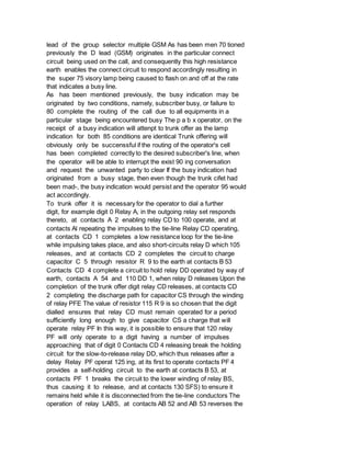
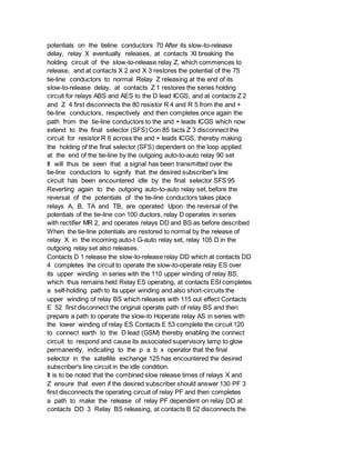
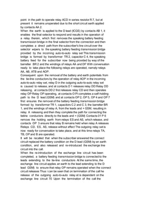
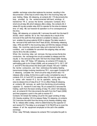
This document describes improvements to telephone systems, specifically regarding private automatic branch exchanges (PABX) serving large numbers of subscribers across multiple locations. It details a system with a parent PABX connected via two-wire tie-lines to satellite automatic exchanges. The parent PABX operator can set up calls to subscribers on satellite exchanges and receive visual supervisory indications of call progress over the tie-lines. This is achieved through signals sent on a non-speaking conductor and distinctive signals involving potential reversals at the tie-line conductors.


![vessels, storerooms, or delivery vans.
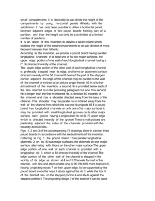
When boards of equal length or used for the walls and for the
intermediate shelves, 80 it may often be advantageous to use the
boards in accordance with the invention for the shelves Only a single
type of board is then necessary, which avoids confusion between the
wall-b)oards and special 85 shelving-boards.
The brackets on which the shelvingboards are laid may be extruded
sections, or they may be of sufficient width so as to form the shelves
themselves Various go lengths of bracket are possible, for example,
short brackets or those of length approximately equal to the boards.
Pound boards in accordance with the invention may be conveniently
produced by 95 the extrusion of a light metal, e g, aluminium alloy.
* Sitemap
* Accessibility
* Legal notice
* Terms of use
* Last updated: 08.04.2015
* Worldwide Database
* 5.8.23.4; 93p
* GB784680 (A)
Description: GB784680 (A) ? 1957-10-16
New disinfectants and preservatives
Description of GB784680 (A)
Translate this text into Tooltip
[75][(1)__Select language]
Translate this text into
The EPO does not accept any responsibility for the accuracy of data
and information originating from other authorities than the EPO; in
particular, the EPO does not guarantee that they are complete,
up-to-date or fit for specific purposes.
PATENT SPECIFICATION
784,680 Date of Application and filing Complete Specification: Aug 7,](https://image.slidesharecdn.com/kpxhzagru2y5r5brcqd9-signature-c3db1d2fb3b39700448b24acaf24871da612fc689ba188497e58593871c899ae-poli-160303210712/85/4271-4275-output-24-320.jpg)

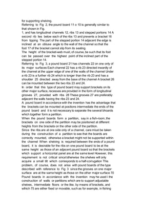
![Improvements in and relating to the production of aromatic oxygen-containing
compounds
Description of GB784681 (A)
Translate this text into Tooltip
[75][(1)__Select language]
Translate this text into
The EPO does not accept any responsibility for the accuracy of data
and information originating from other authorities than the EPO; in
particular, the EPO does not guarantee that they are complete,
up-to-date or fit for specific purposes.
COMPLETE SPECIFICATION
Improvements in and relating to the Production of Aromatic
Oxygen-Containing Compound
We, We, IMPERIAL CHEMICAL INDUSTRIES LIMITE, a British. Company of
Imperial
Chemical House, Millbank, London, S. W. 1, do hereby declare the
invention, for which we pray that a patent may be granted to us, and)
the method by which it is to be performed, to be particularly
described in and by the following statement:
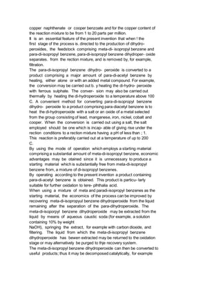
This invention relates to the production of para-di-acetyl bienzene.
According to the present invention there is provided a process for the
production of para-di-acetyl benzene in which feedstock comprising
para-di-isopropyl benzene is subjected under substantially anhydrous
conditions to oxidation with a gas comprising free oxygen at elevated
temperatures and in which the oxidation is: either conducted directly
in the substantial absence of meta-di-isopropyl benzene to give a
product comprising a substantial amount of para-di-acetyl benzene,
using a catalyst comprising a saltor oxide of a metal selected from
the group consisting of lead, manganese, iron, nickel, cobalt and
copper, at a temperature above 100 C; or the feedstock contains at
least 5% by volume of meta-di-isopropyl benzene and the oxidation is
carried out to give para-di-iso-propyl benzene dihydroperoxide and is
conducted in the presence of two alkaline stabilizing agents, one of
which is a carbonate of an alkali metal or of an alkaline earch metal
or magnesium and the second of which is an alkali metal or an alkaline
earch metal or magnesium salt of a weak organic acid, as hereinafter
defined, at a temperature of up to 125 C., the resulting
paradi-isopropyl benzene dihydroperoxide being separated off and
heated so that it decomposes to give para-di-acetyl benzene as a major](https://image.slidesharecdn.com/kpxhzagru2y5r5brcqd9-signature-c3db1d2fb3b39700448b24acaf24871da612fc689ba188497e58593871c899ae-poli-160303210712/85/4271-4275-output-28-320.jpg)


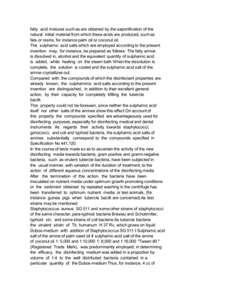
![FR1098383 (A)
FR1098383 (A) less
Translate this text into Tooltip
[79][(1)__Select language]
Translate this text into
The EPO does not accept any responsibility for the accuracy of data
and information originating from other authorities than the EPO; in
particular, the EPO does not guarantee that they are complete,
up-to-date or fit for specific purposes.
COMPLETE SPECIFICATION
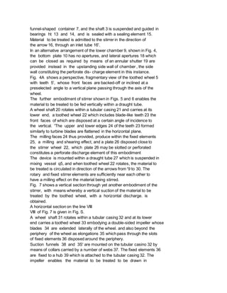
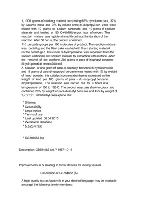
Improvements in or relating to Stirrer Devices for Mixing Vessels
I, ERNST ALFRED REIFFEN, a German
National, of 6, Kirchstrasse, Kassel-Wilhelmshoehe, Germany, do hereby
declare the invention, for which I pray that a patent may be granted
to me, and the method by which it is to be performed, to be
particularly described in and by the following statement:
The present invention concerns stirrers which are used in stationary
mixing vessels and employ as the means for mixing, toothed wheels
whose teeth, when in rotation, pass through the slots of stationary
comb-like bodies disposed free-standing at a distance from each other.
One embodiment of such a mixing device is described, for instance, in
the Specification of British Patent No.
680,309,
According to the present invention a stirring device comprises a
vertically disposed shaft and driving means therefor, a rotary
stirring wheel, having peripheral teeth or blades, mounted on said
shaft, a plurality of radially disposed fixed elements free standing
at a distance from one another, and presenting slots to the stirring
wheel, through which slots the teeth or blades of the stirring wheel
can pass so as to provide a grinding and shearing action, and a
perforate discharge element disposed close to the wheel whereby, in
use, the teeth or blades of the wheel cause a continuous flow of
material being treated in an axial or radial direction through said
discharge element.
The arrangement may be modified and disposed in various manners. There
may be, for example a funnel-shaped container whose lower end is
attached to a lower chamber in which the stirring wheel is disposed.
Either in the bottom or in the upstanding side wall of the lower
chamber, discharge apertures may be provided whose cross-sectional
area is adjustable by means of a shutter. With this controlling
shutter the residence time of the material to be treated within the](https://image.slidesharecdn.com/kpxhzagru2y5r5brcqd9-signature-c3db1d2fb3b39700448b24acaf24871da612fc689ba188497e58593871c899ae-poli-160303210712/85/4271-4275-output-34-320.jpg)