This document summarizes a patent for an improved paper pattern that can be temporarily bonded to fabric. The pattern is made of thin, flexible paper with markings on top. The underside has a heat-sealable, lubricous resin that is non-adhesive at room temperature but becomes adhesive when heated. This allows the pattern to be temporarily bonded to fabric to facilitate needlework while maintaining lubricity for easy needle passage. The resin may be an ethylene polymer, vinyl chloride polymer, or other specified thermoplastic. Figures show applying multiple patterns to fabric with an iron, an enlarged cross-section, and joining cut fabric pieces with attached patterns.


![FR1105635 (A) US2756434 (A) less
Translate this text into Tooltip
[81][(1)__Select language]
Translate this text into
The EPO does not accept any responsibility for the accuracy of data
and information originating from other authorities than the EPO; in
particular, the EPO does not guarantee that they are complete,
up-to-date or fit for specific purposes.
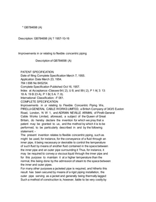
PATENT SPECIFICATION
7849700 Date of Application and filing Complete Specification: May 28,
1954.
Application mode in United States of America on June 2, 1953.
Complete Specification Published: Oct 16, 1957.
Index at acceptance:-Classes 112, F 5; 140, El A; and 141, C 3.
Internatiknal Clessification:-f 41 lh.
COMPLETE SPECIFICATION
Improvements in or relating to Paper Patterns I, RICHARD Ricic, a
Citizen of the United States of America, of Livingston Road, Bellport,
State of New York, United States of America, do hereby declare the
invention, for which I pray that a patent may be granted to me, and
the method by which it is to be performed, to be particularly
described in and by the following statement:-
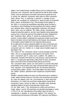
The present invention relates to a paper pattern for manufacturing
garments or the like for embroidering a decorative design on a fabric
or garment.
According to the present invention there is provided a paper pattern,
adapted to be temporarily bonded to a fabric and to readily permit the
passage of a needle and thread therethrough while bonded to said
fabric in manufacture of a garment or in embroidery of a decorative
design on said fabric, comprising a thin, flexible paper having
appropriate indicia, including sewing indicia, marked on its top
surface and having on the undersurface a lubricous, thermoplastic,
heat-sealable resin which is non-adhesive in nature at normal room
temperature, and which becomes plastic and adhesive in nature on the
application of heat, whereby said pattern may be temporarily bonded to
a fabric, said resin remaining lubricous after the application of heat
to permit and facilitate the passage of a needle and thread
therethrough while said pattern is bonded to a fabric, said resin
being selected from the group consisting of ethylene polymers, vinyl
chloride polymers, vinylidene chloride polymers, copolymers of vinyl
chloride and vinyl acetate, polyvinyl acetals, thermoplastic](https://image.slidesharecdn.com/crjp675rouvnjcjuvjxq-signature-c3db1d2fb3b39700448b24acaf24871da612fc689ba188497e58593871c899ae-poli-160303210712/85/4291-4295-output-7-320.jpg)

![present Application,
* Sitemap
* Accessibility
* Legal notice
* Terms of use
* Last updated: 08.04.2015
* Worldwide Database
* 5.8.23.4; 93p
* GB784701 (A)
Description: GB784701 (A) ? 1957-10-16
Improvements in or relating to method of manufacturing garments using paper
patterns
Description of GB784701 (A)
A high quality text as facsimile in your desired language may be available
amongst the following family members:
FR1105635 (A) US2756434 (A)
FR1105635 (A) US2756434 (A) less
Translate this text into Tooltip
[81][(1)__Select language]
Translate this text into
The EPO does not accept any responsibility for the accuracy of data
and information originating from other authorities than the EPO; in
particular, the EPO does not guarantee that they are complete,
up-to-date or fit for specific purposes.
PATENT SPECIFICATION
7349701 Date of Applica Lion and filing Complete ___ i
Specification: May 28, 1954 No 14134/56.
Application made in United States of America on June 2, 1953.
(Divided out of No 784,700).
Complete Specification Published: Oct 16, 1957.](https://image.slidesharecdn.com/crjp675rouvnjcjuvjxq-signature-c3db1d2fb3b39700448b24acaf24871da612fc689ba188497e58593871c899ae-poli-160303210712/85/4291-4295-output-13-320.jpg)


![Improvements in or relating to moulded or cast products and the making of
moulds therefor
Description of GB784702 (A)
Translate this text into Tooltip
[75][(1)__Select language]
Translate this text into
The EPO does not accept any responsibility for the accuracy of data
and information originating from other authorities than the EPO; in
particular, the EPO does not guarantee that they are complete,
up-to-date or fit for specific purposes.
PATENT SPECIFICATION
Inventor: FREDERICK LEWIS DAVIS Date of filing Complete Specification
Dec 20, 1955.
Application Date Nov 25, 1954.
Complete Specification Published Oct 16, 1957.
784,702 No 34219/54.
Index at Acceptance:-Class 87 ( 2), A 1 R( 14 C 2: 20: 68 73), A 7 (A:
CX).
International Classification: -B 29 c, d, g.
COMPLETE SPECIFICATION
Improvements in or relating to Moulded or Cast Products and the making
of Moulds therefor We, LONDON RUBBER COMPANY LIMITED, a British
Company, of Hall Lane, Chingford, London, E 4 do hereby declare the
invention, for which we pray that a patent may be granted to us, and
the method by which it is to be performed, to be particularly
described in and by the following statement:-
This invention relates to moulded or cast products and to the making
of moulds therefor, and has for its primary object to provide an
improved method of producing moulds.
According to the invention, a mould for a moulded or cast product is
produced by forming a thin flexible envelope having the shape of the
mould cavity, filling the said envelope with an easily removable
filling material, applying plaster or other material to the exterior
of the said envelope to form the mould, and removing the filling
material with or without the envelope to leave a cavity in the mould
of the required shape.
in a modification of the method according to the invention, the
filling material is a lowmelting point material poured into the](https://image.slidesharecdn.com/crjp675rouvnjcjuvjxq-signature-c3db1d2fb3b39700448b24acaf24871da612fc689ba188497e58593871c899ae-poli-160303210712/85/4291-4295-output-20-320.jpg)


![[Writing Sample] USPTO Office Action Response by Bryan Johnson](https://cdn.slidesharecdn.com/ss_thumbnails/writingsampleptoofficeactionresponsebjohnson-140103143821-phpapp02-thumbnail.jpg?width=640&height=640&fit=bounds)


