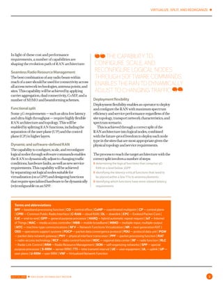
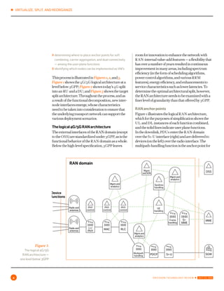
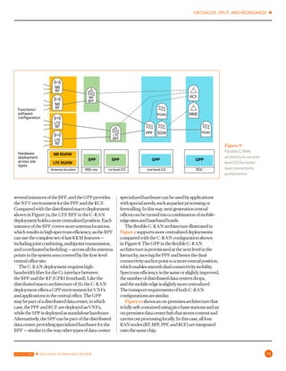
VIRTUALIZE, SPLIT, AND REORGANIZE ✱
JULY 22, 2016 ✱ ERICSSON TECHNOLOGY REVIEW 1
ERICSSON
TECHNOLOGY
RF
RF
BPF
RCF
PPF
C H A R T I N G T H E F U T U R E O F I N N O V A T I O N V O L U M E 9 3 | # 6 ∙ 2 0 1 6
4G/5GRANARCHITECTURE:
HOWASPLITCANMAKE
THEDIFFERENCE
✱ VIRTUALIZE, SPLIT, AND REORGANIZE
2 ERICSSON TECHNOLOGY REVIEW ✱ JULY 22, 2016
ERIK WESTERBERG
As 5g evolves, many innovative services like extreme mobile broadband and
long-range massive mtc will come into play. In line with the evolution of 4g and
the introduction of 5g, ran architecture is undergoing a transformation: to
increase deployment flexibility and network dynamicity, enabling networks to
meet increasing performance requirements, while at the same time keeping
a lid on the total cost of ownership. The proposed future-proof software-
configurable split architecture will be able to support new services, deployed
on general-purpose and specialized hardware, with functions ideally placed to
maximize scalability, spectrum, and energy efficiency, all while supporting the
concept of network slicing.
t h e r e q u i r e m e n t s created by
extreme mbb, the IoT, and massive mtc call
for an alternative to today’s deployment
architectures. The changes to architecture
include the capability to place selected
functions closer to the network edge, for
example, and the ability to increase ran
resilience. Cost is naturally a factor, as
spectrum availability and site infrastructure
continue to dominate operator expenditure
for wide-area systems. The evolution of
ran architecture therefore needs to include
measures for enhanced spectrum efficiency
that are harmonized with other improvements
in the areas of hardware performance and
energy efficiency.
4G/5GRAN
HOW A SPLIT CAN MAKE THE DIFFERENCE
architecture
VIRTUALIZE, SPLIT, AND REORGANIZE ✱
JULY 22, 2016 ✱ ERICSSON TECHNOLOGY REVIEW 3
In light of these cost and performance
requirements, a number of capabilities are
shaping the evolution path of ran architecture:
SeamlessRadioResourceManagement
Thebestcombinationofanyradiobeamwithin
reachofausershouldbeusedforconnectivityacross
allaccessnetworktechnologies,antennapoints,and
sites.Thiscapabilitywillbeachievedbyapplying
carrieraggregation,dualconnectivity,comp,anda
numberofmimo andbeamformingschemes.
Functionalsplit
Some5g requirements—suchasultra-lowlatency
andultra-highthroughput—requirehighlyflexible
ran architectureandtopology.Thiswillbeenabled
bysplittingran functions,includingtheseparation
oftheuserplane(up)andthecontrolplane(cp)in
higherlayers.
Dynamicandsoftware-definedran
Thecapabilitytoconfigure,scale,andreconfigure
logicalnodesthroughsoftwarecommandsenables
theran todynamicallyadjusttochangingtraffic
conditions,hardwarefaults,aswellasnewservice
requirements.Thiscapabilitywillbeachieved
byseparatingoutlogicalnodessuitablefor
virtualization(onagpp)anddesigningfunctions
thatrequirespecializedhardwaretobedynamically
(re)configurableonanspp.
Deploymentflexibility
Deploymentflexibilityenablesanoperatortodeploy
andconfiguretheran withmaximumspectrum
efficiencyandserviceperformanceregardlessofthe
sitetopology,transportnetworkcharacteristics,and
spectrumscenario.
Thisisachievedthroughacorrectsplitoftheran
architectureintologicalnodes,combinedwiththe
future-prooffreedomtodeployeachnodetypein
thesitesthataremostappropriategiventhephysical
topologyandservicerequirements.
Theprocesstoreachthetargetarchitecturewiththe
correctsplitinvolvesanumberofsteps:
〉〉 determining the logical functions that comprise 5g ran
on a level below 3gpp
〉〉 identifying the latency-critical functions that need to
be placed within a few ttis to antenna elements
〉〉 identifying which functions have more relaxed latency
requirements
Terms and abbreviations
bpf — baseband processing function | co — central office | comp — coordinated multipoint | cp — control plane
| cpri — Common Public Radio Interface | c-ran — cloud RAN | dl — downlink | epc — Evolved Packet Core |
e2e — end-to-end | gpp — general purpose processor | harq — hybrid automatic repeat request | iot — Internet
of Things | mac — media access controller | mbb — mobile broadband | mimo — multiple-input, multiple-output |
mtc — machine-type communications | nfv — Network Functions Virtualization | nr — next generation rat | oss
— operations support systems | pdcp — packet data convergence protocol | pdu — protocol data unit | pgw —
packet data network gateway | phy — physical interface transceiver | ppf — packet processing function | rat —
radio-access technology | rcf — radio control function | rdc — regional data center | rf — radio function | rlc —
Radio Link Control | rrm — Radio Resource Management | son — self-organizing networks | spp — special purpose
processor | s-rrm — server rrm | tti — time transmit interval | ue — user equipment | ul — uplink | up — user
plane | u-rrm — user rrm | vnf — Virtualized Network Function
THE CAPABILITY TO
CONFIGURE, SCALE, AND
RECONFIGURE LOGICAL NODES
THROUGH SOFTWARE COMMANDS
ENABLES THE RAN TO DYNAMICALLY
ADJUST TO CHANGING TRAFFIC
✱ VIRTUALIZE, SPLIT, AND REORGANIZE
4 ERICSSON TECHNOLOGY REVIEW ✱ JULY 22, 2016
RAN domain
Device
functions
OSS
MME
SGW
Radioand
antennas
PHY
control
PHY
control
PHY
control
L1/
PHY
MAC RLC
SysArea
handling
UE
handling
Frame
handling
Multipath
handling
PDCP S1-U
S1-
MME
Radioand
antennas
Mgmtand
analytics
Mgmtand
analytics
Mgmtand
analytics
Mgmt
andSON
Figure 1:
The logical 4g/5g
ran architecture —
one level below 3gpp
〉〉 determining where to place anchor points for soft
combining, carrier aggregation, and dual connectivity
— among the user-plane functions
〉〉 identifying which nodes can be implemented as vnfs
ThisprocessisillustratedinFigures 1,2,and3.
Figure 1showsthe4g/5g logicalarchitectureata
levelbelow3gpp;Figure 2showstoday’s4g split
intoan ru andadu;andFigure 3showsthetarget
splitarchitecture.Throughouttheprocess,andas
aresultofthefunctionaldecomposition,newinter-
nodeinterfacesemerge,whosecharacteristics
needtobetakenintoconsiderationtoensurethat
theunderlyingtransportnetworkcansupportthe
variousdeploymentscenarios.
Thelogical4g/5g ran architecture
Theexternalinterfacesoftheran domain(except
totheoss)arestandardizedunder3gpp,asisthe
functionalbehavioroftheran domainasawhole.
Belowthehigh-levelspecification,3gpp leaves
roomforinnovationtoenhancethenetworkwith
ran-internalvalue-addfeatures—aflexibilitythat
hasoveranumberofyearsresultedincontinuous
improvementinmanyareas,includingspectrum
efficiency(intheformofschedulingalgorithms,
powercontrolalgorithms,andvariousrrm
features),energyefficiency,andenhancementsto
servicecharacteristicssuchaslowerlatencies.To
determinetheoptimalarchitecturalsplit,however,
theran architectureneedstobeexaminedwitha
finerlevelofgranularitythanthatofferedby3gpp.
ran anchorpoints
Figure1illustratesthelogicalran architecture,
whichforthepurposesofsimplificationshowsthe
ul and dl instancesofeachfunctioncombined,
andthesolidlinesindicateuserplanefunctions.
Inthedownlink,pdus entertheran domain
overthes1-u interface(right)andaredeliveredto
devices(ontheleft)overtheradiointerface.The
multipath-handlingfunctionistheanchorpointfor
VIRTUALIZE, SPLIT, AND REORGANIZE ✱
JULY 22, 2016 ✱ ERICSSON TECHNOLOGY REVIEW 5
Baseband
processing
function
Radio
function
Radio
control
function
RF
RCF
Device
functions
OSS
MME
SGW
Radioand
antennas
PHY
control
PHY
control
PHY
control
L1/
PHY
MAC RLC
SysArea
handling
UE
handling
Frame
handling
Multipath
handling
PDCP S1-U
S1-
MME
Mgmtand
analytics
Mgmtand
analytics
Mgmtand
analytics
Mgmt
andSON
Radioand
antennas
Packet
processing
functionPPF
BPF
Fast
S-RRM
Fasy
U-RRM
Device
functions
OSS
MME
SGW
Radioand
antennas
PHY
control
L1/
PHY
MAC RLC
SysArea
handling
UE
handling
Frame
handling
Multipath
handling
PDCP S1-U
S1-
MME
Mgmtand
analytics
Mgmtand
analytics
Mgmtand
analytics
Mgmt
andSON
Radioand
antennas
DU functionRU
function
RF
BPF
Figure 2:
Logical ran
architecture —
present split into an
ru function and a du
function
Figure 3:
Logical ran
architecture —
target split into the
functions rf, bpf,
ppf, and rcft
✱ VIRTUALIZE, SPLIT, AND REORGANIZE
6 ERICSSON TECHNOLOGY REVIEW ✱ JULY 22, 2016
dualconnectivity,whichschedulesindividualpdcp
pdus inthesameuser-datastreamtodifferentrlc
instances,possiblyondifferentrats.Inthisway,
asingle ue cansimultaneouslyreceiveandsend
dataoverdifferentradiochannels—forexample,
one nr andonelte channel—thatareconnected
todifferentsites.Themac functionistheanchor
pointforcarrieraggregation,whichschedules
mac pdus toeachuseroveramultitudeof4g or
5g carriers.Themac functionhandlescomp and
multi-beamtransmissions.Intheuplink,thel1/phy
functionperformssoftcombining,themac function
aggregates ul dataincarrieraggregation,and
multipathhandlingaggregatesdatareceivedfrom
dualconnectivity ul datastreams.
Theharq loop
3gpp specifiesretransmissionperiodsandresponse
timesattheradiolevelbetweenthe ue andthe
networkastheharq loop,whichincludes:theair-
interfacetransmissiontime,completiontimesfor
rf-l1/phy-mac functions,andrf-l1/phy-mac
functionsintheue.
Theloopresultsinastandardizedround-trip
latencybudgetof3msforlte,anddownto200µs
fornr.Theran functionsparticipatingintheloop
worksynchronouslywiththeair-interfacetti,while
thepdcp andmultipathhandlingfunctionfeedand
receivepacketstravelingtoandfromtherlc layer
asynchronously—whichhasimplicationsforthe
splitarchitecture.
Controlplanefunctions
Runtimecontrolfunctionscangenerallybedivided
intothreecategories,dependingonwhetherthey:
actonaper-userbasis(u-rrm),controlspectrum
onasystemlevel(s-rrm),ormanageinfrastructure
andothercommonresources.
Theu-rrm functionsincludemeasurement
reporting,selectionofmodulationandcoding
schemes,per-ue bearerhandling,andhandover
execution.Thefunctionsinfastu-rrm actwithin
theharq loopandservetheschedulerwith
processedreal-timeper-ue information.Incontrast,
theu-rrm function(ue-handling)worksonatime
scaleof10msandabove,includingbearerhandling,
per-ue policyhandling,handoffcontrol,andmore.
Functionsthatcontrolspectrumonthesystem
levelincluderadioscheduling,distributionof
thepowerbudgetacrossactiveues,andsystem-
initiatedload-sharinghandovers.Thefasts-rrm
operatingwithintheharq loopisresponsiblefor
radioschedulingandfunctionsintightcoordination
withthemac andrlc.System-areahandlers—such
asloadsharing,systeminformationcontrol,and
dual-connectivitycontrol—controlspectrumona
10mstimescale,orslower.
Functionsthatcontrolinfrastructureand
commonresources—otherthanspectrum—
includehandlingoftransport,connectivity,
hardware,andenergy.Byallowingthecontrol
functionsforspectrum,transport,infrastructure,
andconnectivitytointeract,aholisticcontrolsystem
forran resourcescanbebuilt.
 
Interfacecharacteristics
Theran harq looptimebudgetofthreettisis
dividedintotimeforprocessing,andtimeforsignals
anddatatotraversethevariousinter-function
interfaces.Thelesstimespentoninterfacesignaling,
themoretimeisavailableforprocessing,which
translatesintolowercostforhardwareandfor
energyconsumption.Tominimizesignalinglatency,
andthusmaximizehardwareefficiency,themac,
rlc,andfast-u/s-rrm functionsshouldrunonthe
samehardwareinstance.Astrafficmovestotheright
inFigure 4,therequirementoninterfacelatency
graduallyrelaxes.
Thecpri scaleswitheffectivecarrierbandwidth
andthenumberofantennaelements.Aninter-site
cpri interfacewithjointcombiningatthecentral
office(co)can,inmanydeployments,resultinagain
inuplinkspectrum.Forlte,thecpri canbeinter-
site(afewgbps),butin nr —withwidercarriersand
moreantennaelements—aninter-sitecpri would
bechallengingfrombothalatencyandbandwidth
perspective.
Theinterfacebetweentherlc andthemultipath
handlerscaleswithuserdataandhasalatency
toleranceintheorderofseveralmilliseconds.This
interfaceislimitedbytheperformanceofthedual
connectivityfeature,whichdegradesgracefullyas
VIRTUALIZE, SPLIT, AND REORGANIZE ✱
JULY 22, 2016 ✱ ERICSSON TECHNOLOGY REVIEW 7
RAN domain
Device
functions
CPRI
Control interfaces, RTT 10-100ms, moderate data volumes
Interfaces contributing to the RAN HARQ loop latency budget
User-plane interfaces, latency tolerance 3–5ms
Mobile backhaul, delay tolerant up to service requirements
OSS
MME
SGW
Radioand
antennas
PHY
control
PHY
control
PHY
control
L1/
PHY
MAC RLC
SysArea
handling
UE
handling
Frame
handling
Multipath
handling
PDCP S1-U
S1-
MME
Mgmtand
analytics
Mgmtand
analytics
Mgmtand
analytics
Mgmt
andSON
Radioand
antennas
Figure 4:
The logical interfaces in the
ran architecture and their
characteristics requirements
theinterfacelatencyincreases.Thisinterfacecan,
therefore,eitherbenodeinternaloranetworked
interfacebetweennodesandevenbetweensitesthat
arenotmorethan3-5msapart.
TheremaininginterfacesinFigure4carryeither
slowcontroldata(indicatedbythebluelines)oruser
databetweentheran andtheepc (s1-u interface).
Atover10ms,thelatencyrequirementsonthese
interfacesarequiterelaxed.
Hardwarerequirements
Controlfunctionsthatareasynchronoustotheradio
interfacetendtobesuitableforvirtualizationand
vnf deployments,astheyaretransactionbasedand
donotinvolveheavypacketprocessing.
Ontheotherhand,functionslikemultipath
handling,pdcp,ands1-u terminationinvolvepacket
processing(encapsulation,headerreading/creation,
encryption/decryption,androuting)andcanbe
challengingtovirtualize.However,iftheunderlying
hardwarecontainscipheringoffloadandpacket-
processingaccelerators,virtualizationispossible
withoutperformancedegradation,andsothese
functionscanbevirtualizedanddeployedinannfv
environment.
Mostran processingcyclesoccurintheharq
synchronousfunctions.Taskslikeuplinkradio
decodingandschedulingare,forexample,highly
processingintense.Andso,themoreprocessingthat
canbecarriedoutintheuplinkdecoding,thebetter
theuplinksensitivity,andthemoreprocessingthat
canbeallocatedtothescheduler,thebettertheuse
ofspectruminboththeuplinkandthedownlink.
Reducingprocessingintheharq synchronous
✱ VIRTUALIZE, SPLIT, AND REORGANIZE
8 ERICSSON TECHNOLOGY REVIEW ✱ JULY 22, 2016
RUHW SPP GPP
Device
functions
Radioand
antennas
PHY
control
Fast
S-RRM
Fast
U-RRM
L1/
PHY
MAC RLC
OSS
MME
SGW
SysArea
handling
UE
handling
Frame
handling
Multipath
handling
PDCP S1-U
S1-
MME
Mgmtand
analytics
Mgmtand
analytics
Mgmt
andSON
Radioand
antennas
Mgmtand
analytics
Figure 5:
Preferred execution
environments for
the various ran
functions
Figure 6:
Hierarchy,
instantiation, and
inter-node interfaces
in the ran split
architecture
Sys area 4Sys area 3Sys area 2
OSS
RCF
MME
RF RF RF RF RF RF
Sys area 1
S1-MME
S1-U CC-IBB-CI
BB-II
BB-UI
C1
RF RF RF RF
BPF1 BPF2 BPF3 BPF4
PPF1 PPF2
SGW
VIRTUALIZE, SPLIT, AND REORGANIZE ✱
JULY 22, 2016 ✱ ERICSSON TECHNOLOGY REVIEW 9
functionsisnotagoodideaifspectrumefficiency
istobemaintainedorimproved.Special-purpose
multi-corehardwareisbestsuitedtothistype
ofprocessing,asitsprice-performanceratiois
presentlyfivetimesthatofsingle-corehardware.
Andso,harq synchronousfunctionsarelikelyto
continuetorunonspecialpurposeprocessor(spp)
hardwareforatleastoneortwomoregenerationsof
ran hardware.
Toavoidflowcontrolissuesbetweenthemac and
therlc —andgiventhelevelofinteractionbetween
theschedulerandrlc —themac,rlc,andthefast
rrm shouldrunonthesamehardwareinstance.
Theresultinghardwareenvironmentisshownin
Figure 5.
Thefunctionsontherightintheillustration(blue
area)runongeneralpurposeprocessors(gpps)that
includehardwareacceleratorsandcipheringoffload
formultipathhandlingandpdcp.Thefunctions
inthemiddle(greenarea)runonsppswithmulti-
corehardwaresuitableforsupportingfunctionsin
theharq loop,andtheradiohardwareisontheleft
(yellowarea).
 
Resultingsplitarchitecture
Basedonfunctionandinterfacecharacteristics,
preferredexecutionenvironment,andspectrum
efficiency,thetargetfunctionalcomposition,which
isshowninFigure 6,includesthefollowinglogical
ran nodes:
Packetprocessingfunction—ppf
Theppf,whichissuitableforvirtualization,contains
user-planefunctionsthatareasynchronoustothe
harq loop,andincludesthepdcp layer—suchas
encryption—andthemultipathhandlingfunction
forthedualconnectivityanchorpointanddata
scheduling.
Basebandprocessingfunction—bpf
Giventhestringentrequirementsforspectrum
efficiency,thebpf benefitsfrombeingplacedonan
spp.Thebpf includesuser-planefunctionsthatare
synchronoustotheharq loop,includingtherlc,
mac,andl1/phy,anditisalsotheanchorpointfor
carrieraggregation(mac)andsoftcombining(l1/
phy).Thebpf containstheper-tti rrm (fastradio
scheduler),andisalsoresponsibleforthecomp,for
theselectionofthemimo scheme,andforbeamand
antennaelements.
Radiofunction—rf
The rf requiresspecialradiohardwareand
includesfunctionssuchasmodulation,d/a
conversion,filtering,andsignalamplification.
Radiocontrolfunction—rcf
Thercf handlesloadsharingamongsystemareas
anddifferentradiotechnologies,aswellastheuse
ofpoliciestocontroltheschedulersinthebpfsand
ppfs.Attheuserandbearerlevel,thercf negotiates
qos andotherpolicieswithotherdomains,andis
responsiblefortheassociatedsla enforcement
intheran.Thercf controlstheoverallran
performancerelativetotheservicerequirement,
createsandmanagesanalyticsdata,andis
responsiblefortheran son functions.Liketheppf,
thercf issuitableforvirtualization.
Thelogicalinterfacesare:
〉〉 	c1—anevolutionofthecpri interface,thisinterface
scaleswitheffectivecarrierbandwidth(carrier
bandwidth×numberofantennastreams)withalatency
requirementofaroundonetti (1msforlte anddownto
67µsfornr).
〉〉 	bb-ui —theuser-planeinterfacebetweentheppf and
thebpf,itcarriespdcp pdus,whichscaleaccordingto
theamountofuserdatasentbythebpf instancetothe
systemarea.
〉〉 bb-ii—theinterfacebetweentwobpf instances,it
carriesuserdataforscenariosthatuseinter-bpf carrier
aggregation(carrieraggregationovertwocarriers
controlledbytwodifferentbpf instances).Thisinterface
alsocarriescontroldatafortheinter-bpf comp,scales
inlinewiththeamountofuserdatatransmitted,andthe
latencyrequirementisthesameasforc1.
〉〉 	bb-ci —thecontrol-planeinterfaceforthebpfs,which
carriescontrolandanalyticsdatafromthebpf tothe
rcf.Thisinterfaceprimarilyscaleswiththevolume
ofanalyticsdata,andat10msormore,thelatency
requirementsarequiterelaxed.
〉〉 	cc-i —thecontrol-planeinterfacefortheppfs,which
✱ VIRTUALIZE, SPLIT, AND REORGANIZE
10 ERICSSON TECHNOLOGY REVIEW ✱ JULY 22, 2016
RCF
RUHW SPP GPP GPP
Antenna
location RBS site
Functions/
software
configuration
Hardware
deployment
across site
types
1 st level CO 2nd level CO RDC
RF
RF
BPF PPF
MME
SGW PGW
Figures 7a and 7b:
Deployment of
hardware and nodes
across site types in a
classic main-remote
deployment — valid
for both lte and nr
RCF
RUHW SPP GPP GPP
Antenna
location RBS site
Functions/
software
configuration
1st level CO 2nd level CO RDC
RF
RF
BPF
PPF
MME
SGW
PGW
VIRTUALIZE, SPLIT, AND REORGANIZE ✱
JULY 22, 2016 ✱ ERICSSON TECHNOLOGY REVIEW 11
carriescontrolandanalyticsdatafromtheppf to
thercf.Likebb-ci,thisinterfacescalesprimarily
accordingtothevolumeofanalyticsdatatransmitted,
andhasrelaxedlatencyrequirementsof10msormore.
Inadeployment,eachfunction(rf,bpf,ppf,
andrfc)isinstantiated.Aninstanceoftheradio
functionswillbeassociatedwithanumberof
antennaelementsatanantennasite,andasetofn rf
instancesareconnectedtooneinstanceofthebpf.
Eachantennaelement(rf)isassociatedwith
onebpf.Hence,abpf instancehandlesthecells
correspondingtothe rf antennaelementsitis
associatedwith.Thesetofcellsunderthecontrol
ofabpf instanceisreferredtoasasystemarea.
Bydefinition,onebpf instancehandlestheradio
transmissionandreceptionoftrafficinitssystem
area.Withinitssystemarea,abpf instance
alsocontrolsbeamforming,power,spectrum,
scheduling,loadsharing,andfastu/s-rrm.
Mobilitywithinasystemareaishiddenunder
thebpf andnotvisibletotheppf ortheepc.A
multitudeofbpf instancesareconnectedtoone
instanceoftheppf.Oneppf instanceistherefore
associatedwithalargenumberofbpfs,aswellas
thetrafficsenttoandbyusersinalargesetofsystem
areas.Asthes1-u terminatesintheppf,ausercan
movearoundwithinthissetofsystemareasorcells
withoutcausingans1orx2handover.Eachinstance
ofthercf canhandleasmalloralargesetofppfs—
andalltheassociatedbpfs.Inthisway,thercf can
keepaholisticviewofanareathatisjustasinglecell,
uptoanareaconsistingofthousandsofcells.With
thisarchitecture,rrm coordinationandspectrum
efficiencywithinasystemareacanbemaximized,
usingthefullsuiteofrrm featuresavailable,which
laysthefoundationfortheapplicationoffuture
innovationsandrrm technologies.
Deploymentalternativesandexamples
Havingdefinedthesplitran architecture,it
ispossibletodescribesomeofthedeployment
alternativesitsupportsandtheassociateddynamics
ofthesoftware-definedradionetwork.Figures 7a
and7bshowadistributedmain-remotemacrosite.
Thehardwaredeployedateachsiteisshownin
thebottomhalfofeachfigure,whilethetoppart
showstheconfigurationofnetworkfunctionsacross
thathardware.Thehardwaredeploymentissemi-
static,butthenetworkfunctionsare(re)configured
usingcommandsormachineinstructions,andare
thereforesoftwaredefined.
Theantennalocationcontainsradiounit
hardwarethathoststherfs.Inthedistributed
main-remotedeployment,afiberlinkconnectsthe
antennalocationtotherbs mainsiteoveracpri
(c1interface).Therbs siteisconfiguredwithan
spp forthebpf,andagpp fortheppf andrcf,and
isconnectedovers1mobilebackhaultransportto
epc gatewaysresidinginamorecentrallylocated
regionaldatacenter(rdc).Inadditiontoproviding
anexecutionenvironmentfortheppf andrcf,the
gpp hardwareoffersavirtualizationenvironment
forvnfsandapplications.
Thisdeploymentenablescomputingatthe
mobileedgeforselectedapplications,users,ordata
streamstobemovedtotherbs sitebymeansofa
systemreconfiguration—orevenautomatically
basedonpoliciesandtraffictriggers.InFigure7b,
avirtualpacketgateway—deployedasavnf —is
locatedattherbs siterunninginthevirtualization
environmentofthegpp.WhileFigures7aand
7bdescribethesamehardwareinstallations,the
configurationof7bsupportscomputingatthe
mobileedgeintherbs site—duetotheabilityto
breakouttrafficinthelocalpacketgatewayfunction.
In7a,allthetrafficisbackhauledtothegatewayin
therdc.Asthehardwaredeploymentsin7aand
7barethesame,theradio-networkarchitecture
differenceiscreatedthroughdynamicsoftware
commands.Inthisway,thenetworkarchitecture
canadaptaccordingtopoliciesandvaryingtraffic
conditions,eitherthroughsoftwareconfigurationor
automatically(automationandson)—whichisthe
basisforsoftware-definedran.
Asecondexample,illustratedinFigure 8,shows
atypicallte c-ran deploymentextendedwith
main-remotenr.AsFigure 8aillustrates,theradio
unithardwareislocatedattheantennalocation,
whilethespp andgpp aredeployedinthecentral
officesites.Thespp hardwarerunsoneorseveral
instancesofthebpf,andthegpp providesthenfv
✱ VIRTUALIZE, SPLIT, AND REORGANIZE
12 ERICSSON TECHNOLOGY REVIEW ✱ JULY 22, 2016
Figure 8a and 8b:
c-ran deployment
with (instance
a) a centralized
packet gateway
and (instance b) a
second instance of
the pgw distributed
to the co site for
local breakout of
selected traffic
NR RUHW
LTE RUHW
SPP SPP GPP GPP
Antenna location RBS site 1st level CO 2nd level CO RDC
NR
RF
NR
RF
LTE
RF
LTE
RF
NR
BPF
LTE
BPF
PPF
RCF
MME
SGW PGW
Functions/
software
configuration
Hardware
deployment
across site
types
NR RUHW
LTE RUHW
SPP SPP GPP GPP
Antenna location RBS site
Functions/
software
configuration
1stlevel CO 2nd level CO RDC
NR
RF
NR
RF
LTE
RF
LTE
RF
NR
BPF
LTE
BPF
PPF
RCF
MME
SGW PGW
1
PGW
2
Hardware
deployment
across site
types
VIRTUALIZE, SPLIT, AND REORGANIZE ✱
JULY 22, 2016 ✱ ERICSSON TECHNOLOGY REVIEW 13
environmentfortheppf andthercf.Compared
withthedistributedmacrodeploymentshownin
Figure 7a,thelte bpf inthec-ran deployment
holdsamorecentralizedposition.Eachinstance
ofthebpf coversmoreantennalocations,which
resultsinhighspectrumefficiency,asthebpf can
usethecompletesetoffastrrm features—including
jointcombining,multipointtransmission,and
coordinatedscheduling—acrossalltheantenna
pointsinthesystemareacoveredbythefirst-level
centralofficesite.
Thec-ran deploymentrequireshigh-bandwidth
fiberforthec1interfacebetweenthebpf andthe
rf (cpri fronthaul).Likethedistributedmacro
architectureof7b,thec-ran deploymentoffersa
gpp environmentforvnfsandapplicationsinthe
centraloffice.Thegpp maybepartofadistributed
datacenter,inwhichcase,theppf andrcf are
deployedasvnfs,whilethespp isdeployedas
standalonehardware.Alternatively,thespp can
bepartofthedistributeddatacenter,providing
specializedhardwareforthebpf —similartothe
wayothertypesofdata-centerspecializedhardware
canbeusedbyapplicationswithspecialneeds,
suchaspacketprocessingorfirewalling.Inthisway,
nextgenerationcentralofficescanbeturnedinto
acombinationofmobile-edgesitesandbaseband
hotels.
Theflexiblec-ran architectureillustratedin
Figure 9supportsmorecentralizeddeployments
comparedwiththec-ran configurationshownin
Figure8.Thegpp intheflexiblec-ran architecture
isprovisionedatthenextlevelinthehierarchy,
movingtheppf andhencethedual-connectivity
anchorpointtoamorecentralposition,which
enablessmoothdualconnectivitymobility.
Spectrumefficiencyisthesameorslightlyimproved,
thenumberofdistributeddatacentersdrops,
andthemobileedgeisslightlymorecentralized.
Thetransportrequirementsofbothc-ran
configurationsaresimilar.
Figure 10showsanon-premisesarchitecturethat
isfullyself-containedusingpicobasestationsandan
on-premisesdatacenterhubthatstorescontentand
carriesoutprocessinglocally.Inthiscase,allfour
ran nodes(rf,bpf,ppf,andrcf)areintegrated
ontothesamechip.
Theidealsplitarchitecturecontainspoolsof
NR RUHW
LTE RUHW
SPP SPP GPP GPP
Antenna location RBS site
Functions/
software
configuration
1st level CO 2nd level CO RDC
NR
RF
NR
RF
LTE
RF
LTE
RF
NR
BPF
LTE
BPF
PPF
RCF
MME
SGW PGW1
PGW2
Hardware
deployment
across site
types
Figure 9:
Flexible c-ran
architecture second-
level co for better
dual connectivity
performance
✱ VIRTUALIZE, SPLIT, AND REORGANIZE
14 ERICSSON TECHNOLOGY REVIEW ✱ JULY 22, 2016
hardware(anspp andgpp)strategicallydeployed
inselectedrbs and co sites.Instancesofthethree
functiontypesbpf,ppf,andrcf —andanyvnfs
inthemobilenetwork—aredynamicallycreated,
modified,scaled,andterminatedbasedonneedand
operatorpolicies.Buildingmobilenetworksinthis
software-definedwayresultsinanarchitecturethat:
〉〉 isreliableandresilient—asitenablesfunctionsto
relocatefollowingahardware,site,orlinkfailure
〉〉 isflexibleandenergyefficient—asitautomatically
adaptstopeaksandtroughsintrafficpatternsand
serviceusage
〉〉 reducestimetomarketfornewservicesandnetwork
features
〉〉 canmaximizespectrumefficiency(minimizecost
forspectrumandsites)giventhegeographyand
sitetopologyofthenetwork,throughitsflexibility
todynamicallydistributethehubpointsforjoint
combining,multipointtransmission,comp,carrier
aggregation,anddualconnectivity
Conclusions
Thedesignofthe4g/5g splitran architecture
focusesonincreasedspectrumefficiency,full
deploymentflexibility,andelasticity;processing
iscarriedoutwhereresourcesareavailableand
needed.Thesplitran architectureconsistsof
thetwouser-planenetworkfunctions:apacket
processingfunction(ppf)andabaseband
processingfunction(bpf),togetherwiththe
antenna-nearradiofunction(rf),andthecontrol-
planeradiocontrolfunction(rcf).
Theppfsandrcfscaneachbedeployedeitherin
classicalpre-integratednodesorinfullyvirtualized
environmentsasvnfsoranycombinationthereof.
Bothfunctionsaresuitableforvirtualizationwith
existingtechnology,withbenefitstotheppf brought
bypacketacceleratorsandcipheringsupportinthe
underlyinghardware.
Inprinciple,thebpf canalsobevirtualized.
However,special-purposehardwareisstillabout
fivetoseventimesmoreefficientthangeneral-
purposehardwareforthetypeofprocessingthebpf
performs,andsoitisexpectedthatthebpf willbe
deployedonanspp foroneortwomoregenerations
ofhardware.
Thercf takesholisticresponsibilityforRadio
ResourceManagement,ran analyticsandson,
itmaintainspolicyandbearerinformation,and
interworkswithnon-ran domainssuchastheepc
Pico site
Functions/
software
deployment
On-premises hub 2nd level CO RDC
RF
RF
BPF
SGW
PGW
Local
cloud
RCF
MME
PPF
PGW
Hardware
deployment
across site
types
Figure 10:
Factory deployment
examples using pico
4g/5g base stations
(green) and with on-
premises breakout
possibility
VIRTUALIZE, SPLIT, AND REORGANIZE ✱
JULY 22, 2016 ✱ ERICSSON TECHNOLOGY REVIEW 15
Erik Westerberg
◆ joined Ericsson from mit,
Massachusetts, the us, in
1996 and is a senior expert
in system and network
architecture. During his
first 10 years at Ericsson, he
worked with development
of the mobile broadband
systems before broadening
his field to include the full
network architecture. He
presently holds the position
of chief network architect
in Ericsson's Business Unit
Network Products. He holds
a Ph.D. in quantum physics
from Stockholm University,
Sweden.
author
andresourceorchestrationlayers.Thercf canbe
centralizedordistributedinaclosedon-premises
factorynetwork,forexample.Deployingtheuser-
planebpf (processingsynchronoustothetti)
andppf (asynchronouspacketprocessing)canbe
achievedinavarietyofways,aslongasthebpf is
withinonetotwottis fromtheantennapoints.The
ppf,ontheotherhand,canbemorecentralized,with
adistanceofupto5-7msfromtheradiofunctions.
Andsouser-planefunctionscanbedeployedto
matchservicerequirements,andmaximizespectrum
efficiencyaccordingtothespectrum,transport,
andsiteavailability,aswellastheparticularlocal
geography.
Thesplitarchitectureresultsinthenecessary
scalingdimensionstosupport5g usecasesand
trafficstructuresinacost-efficientway.Itsflexibility
anddecouplingofhardwarefromsoftwareenables
asoftware-definedelasticresilientran.Italso
guaranteesthatran architectureisfuture-proof.
Asanevolutionof 4g ran,thesplitcanbegradually
introducedinlinewithbusinessneeds.
✱ VIRTUALIZE, SPLIT, AND REORGANIZE
16 ERICSSON TECHNOLOGY REVIEW ✱ JULY 22, 2016
ISSN 0014-0171
284 23-3283 | Uen
© Ericsson AB 2016
Ericsson
SE-164 83 Stockholm, Sweden
Phone: +46 10 719 0000

4G/5G RAN architecture: how a split can make the difference

  • 1.
    VIRTUALIZE, SPLIT, ANDREORGANIZE ✱ JULY 22, 2016 ✱ ERICSSON TECHNOLOGY REVIEW 1 ERICSSON TECHNOLOGY RF RF BPF RCF PPF C H A R T I N G T H E F U T U R E O F I N N O V A T I O N V O L U M E 9 3 | # 6 ∙ 2 0 1 6 4G/5GRANARCHITECTURE: HOWASPLITCANMAKE THEDIFFERENCE
  • 2.
    ✱ VIRTUALIZE, SPLIT,AND REORGANIZE 2 ERICSSON TECHNOLOGY REVIEW ✱ JULY 22, 2016 ERIK WESTERBERG As 5g evolves, many innovative services like extreme mobile broadband and long-range massive mtc will come into play. In line with the evolution of 4g and the introduction of 5g, ran architecture is undergoing a transformation: to increase deployment flexibility and network dynamicity, enabling networks to meet increasing performance requirements, while at the same time keeping a lid on the total cost of ownership. The proposed future-proof software- configurable split architecture will be able to support new services, deployed on general-purpose and specialized hardware, with functions ideally placed to maximize scalability, spectrum, and energy efficiency, all while supporting the concept of network slicing. t h e r e q u i r e m e n t s created by extreme mbb, the IoT, and massive mtc call for an alternative to today’s deployment architectures. The changes to architecture include the capability to place selected functions closer to the network edge, for example, and the ability to increase ran resilience. Cost is naturally a factor, as spectrum availability and site infrastructure continue to dominate operator expenditure for wide-area systems. The evolution of ran architecture therefore needs to include measures for enhanced spectrum efficiency that are harmonized with other improvements in the areas of hardware performance and energy efficiency. 4G/5GRAN HOW A SPLIT CAN MAKE THE DIFFERENCE architecture
  • 3.
    VIRTUALIZE, SPLIT, ANDREORGANIZE ✱ JULY 22, 2016 ✱ ERICSSON TECHNOLOGY REVIEW 3 In light of these cost and performance requirements, a number of capabilities are shaping the evolution path of ran architecture: SeamlessRadioResourceManagement Thebestcombinationofanyradiobeamwithin reachofausershouldbeusedforconnectivityacross allaccessnetworktechnologies,antennapoints,and sites.Thiscapabilitywillbeachievedbyapplying carrieraggregation,dualconnectivity,comp,anda numberofmimo andbeamformingschemes. Functionalsplit Some5g requirements—suchasultra-lowlatency andultra-highthroughput—requirehighlyflexible ran architectureandtopology.Thiswillbeenabled bysplittingran functions,includingtheseparation oftheuserplane(up)andthecontrolplane(cp)in higherlayers. Dynamicandsoftware-definedran Thecapabilitytoconfigure,scale,andreconfigure logicalnodesthroughsoftwarecommandsenables theran todynamicallyadjusttochangingtraffic conditions,hardwarefaults,aswellasnewservice requirements.Thiscapabilitywillbeachieved byseparatingoutlogicalnodessuitablefor virtualization(onagpp)anddesigningfunctions thatrequirespecializedhardwaretobedynamically (re)configurableonanspp. Deploymentflexibility Deploymentflexibilityenablesanoperatortodeploy andconfiguretheran withmaximumspectrum efficiencyandserviceperformanceregardlessofthe sitetopology,transportnetworkcharacteristics,and spectrumscenario. Thisisachievedthroughacorrectsplitoftheran architectureintologicalnodes,combinedwiththe future-prooffreedomtodeployeachnodetypein thesitesthataremostappropriategiventhephysical topologyandservicerequirements. Theprocesstoreachthetargetarchitecturewiththe correctsplitinvolvesanumberofsteps: 〉〉 determining the logical functions that comprise 5g ran on a level below 3gpp 〉〉 identifying the latency-critical functions that need to be placed within a few ttis to antenna elements 〉〉 identifying which functions have more relaxed latency requirements Terms and abbreviations bpf — baseband processing function | co — central office | comp — coordinated multipoint | cp — control plane | cpri — Common Public Radio Interface | c-ran — cloud RAN | dl — downlink | epc — Evolved Packet Core | e2e — end-to-end | gpp — general purpose processor | harq — hybrid automatic repeat request | iot — Internet of Things | mac — media access controller | mbb — mobile broadband | mimo — multiple-input, multiple-output | mtc — machine-type communications | nfv — Network Functions Virtualization | nr — next generation rat | oss — operations support systems | pdcp — packet data convergence protocol | pdu — protocol data unit | pgw — packet data network gateway | phy — physical interface transceiver | ppf — packet processing function | rat — radio-access technology | rcf — radio control function | rdc — regional data center | rf — radio function | rlc — Radio Link Control | rrm — Radio Resource Management | son — self-organizing networks | spp — special purpose processor | s-rrm — server rrm | tti — time transmit interval | ue — user equipment | ul — uplink | up — user plane | u-rrm — user rrm | vnf — Virtualized Network Function THE CAPABILITY TO CONFIGURE, SCALE, AND RECONFIGURE LOGICAL NODES THROUGH SOFTWARE COMMANDS ENABLES THE RAN TO DYNAMICALLY ADJUST TO CHANGING TRAFFIC
  • 4.
    ✱ VIRTUALIZE, SPLIT,AND REORGANIZE 4 ERICSSON TECHNOLOGY REVIEW ✱ JULY 22, 2016 RAN domain Device functions OSS MME SGW Radioand antennas PHY control PHY control PHY control L1/ PHY MAC RLC SysArea handling UE handling Frame handling Multipath handling PDCP S1-U S1- MME Radioand antennas Mgmtand analytics Mgmtand analytics Mgmtand analytics Mgmt andSON Figure 1: The logical 4g/5g ran architecture — one level below 3gpp 〉〉 determining where to place anchor points for soft combining, carrier aggregation, and dual connectivity — among the user-plane functions 〉〉 identifying which nodes can be implemented as vnfs ThisprocessisillustratedinFigures 1,2,and3. Figure 1showsthe4g/5g logicalarchitectureata levelbelow3gpp;Figure 2showstoday’s4g split intoan ru andadu;andFigure 3showsthetarget splitarchitecture.Throughouttheprocess,andas aresultofthefunctionaldecomposition,newinter- nodeinterfacesemerge,whosecharacteristics needtobetakenintoconsiderationtoensurethat theunderlyingtransportnetworkcansupportthe variousdeploymentscenarios. Thelogical4g/5g ran architecture Theexternalinterfacesoftheran domain(except totheoss)arestandardizedunder3gpp,asisthe functionalbehavioroftheran domainasawhole. Belowthehigh-levelspecification,3gpp leaves roomforinnovationtoenhancethenetworkwith ran-internalvalue-addfeatures—aflexibilitythat hasoveranumberofyearsresultedincontinuous improvementinmanyareas,includingspectrum efficiency(intheformofschedulingalgorithms, powercontrolalgorithms,andvariousrrm features),energyefficiency,andenhancementsto servicecharacteristicssuchaslowerlatencies.To determinetheoptimalarchitecturalsplit,however, theran architectureneedstobeexaminedwitha finerlevelofgranularitythanthatofferedby3gpp. ran anchorpoints Figure1illustratesthelogicalran architecture, whichforthepurposesofsimplificationshowsthe ul and dl instancesofeachfunctioncombined, andthesolidlinesindicateuserplanefunctions. Inthedownlink,pdus entertheran domain overthes1-u interface(right)andaredeliveredto devices(ontheleft)overtheradiointerface.The multipath-handlingfunctionistheanchorpointfor
  • 5.
    VIRTUALIZE, SPLIT, ANDREORGANIZE ✱ JULY 22, 2016 ✱ ERICSSON TECHNOLOGY REVIEW 5 Baseband processing function Radio function Radio control function RF RCF Device functions OSS MME SGW Radioand antennas PHY control PHY control PHY control L1/ PHY MAC RLC SysArea handling UE handling Frame handling Multipath handling PDCP S1-U S1- MME Mgmtand analytics Mgmtand analytics Mgmtand analytics Mgmt andSON Radioand antennas Packet processing functionPPF BPF Fast S-RRM Fasy U-RRM Device functions OSS MME SGW Radioand antennas PHY control L1/ PHY MAC RLC SysArea handling UE handling Frame handling Multipath handling PDCP S1-U S1- MME Mgmtand analytics Mgmtand analytics Mgmtand analytics Mgmt andSON Radioand antennas DU functionRU function RF BPF Figure 2: Logical ran architecture — present split into an ru function and a du function Figure 3: Logical ran architecture — target split into the functions rf, bpf, ppf, and rcft
  • 6.
    ✱ VIRTUALIZE, SPLIT,AND REORGANIZE 6 ERICSSON TECHNOLOGY REVIEW ✱ JULY 22, 2016 dualconnectivity,whichschedulesindividualpdcp pdus inthesameuser-datastreamtodifferentrlc instances,possiblyondifferentrats.Inthisway, asingle ue cansimultaneouslyreceiveandsend dataoverdifferentradiochannels—forexample, one nr andonelte channel—thatareconnected todifferentsites.Themac functionistheanchor pointforcarrieraggregation,whichschedules mac pdus toeachuseroveramultitudeof4g or 5g carriers.Themac functionhandlescomp and multi-beamtransmissions.Intheuplink,thel1/phy functionperformssoftcombining,themac function aggregates ul dataincarrieraggregation,and multipathhandlingaggregatesdatareceivedfrom dualconnectivity ul datastreams. Theharq loop 3gpp specifiesretransmissionperiodsandresponse timesattheradiolevelbetweenthe ue andthe networkastheharq loop,whichincludes:theair- interfacetransmissiontime,completiontimesfor rf-l1/phy-mac functions,andrf-l1/phy-mac functionsintheue. Theloopresultsinastandardizedround-trip latencybudgetof3msforlte,anddownto200µs fornr.Theran functionsparticipatingintheloop worksynchronouslywiththeair-interfacetti,while thepdcp andmultipathhandlingfunctionfeedand receivepacketstravelingtoandfromtherlc layer asynchronously—whichhasimplicationsforthe splitarchitecture. Controlplanefunctions Runtimecontrolfunctionscangenerallybedivided intothreecategories,dependingonwhetherthey: actonaper-userbasis(u-rrm),controlspectrum onasystemlevel(s-rrm),ormanageinfrastructure andothercommonresources. Theu-rrm functionsincludemeasurement reporting,selectionofmodulationandcoding schemes,per-ue bearerhandling,andhandover execution.Thefunctionsinfastu-rrm actwithin theharq loopandservetheschedulerwith processedreal-timeper-ue information.Incontrast, theu-rrm function(ue-handling)worksonatime scaleof10msandabove,includingbearerhandling, per-ue policyhandling,handoffcontrol,andmore. Functionsthatcontrolspectrumonthesystem levelincluderadioscheduling,distributionof thepowerbudgetacrossactiveues,andsystem- initiatedload-sharinghandovers.Thefasts-rrm operatingwithintheharq loopisresponsiblefor radioschedulingandfunctionsintightcoordination withthemac andrlc.System-areahandlers—such asloadsharing,systeminformationcontrol,and dual-connectivitycontrol—controlspectrumona 10mstimescale,orslower. Functionsthatcontrolinfrastructureand commonresources—otherthanspectrum— includehandlingoftransport,connectivity, hardware,andenergy.Byallowingthecontrol functionsforspectrum,transport,infrastructure, andconnectivitytointeract,aholisticcontrolsystem forran resourcescanbebuilt.   Interfacecharacteristics Theran harq looptimebudgetofthreettisis dividedintotimeforprocessing,andtimeforsignals anddatatotraversethevariousinter-function interfaces.Thelesstimespentoninterfacesignaling, themoretimeisavailableforprocessing,which translatesintolowercostforhardwareandfor energyconsumption.Tominimizesignalinglatency, andthusmaximizehardwareefficiency,themac, rlc,andfast-u/s-rrm functionsshouldrunonthe samehardwareinstance.Astrafficmovestotheright inFigure 4,therequirementoninterfacelatency graduallyrelaxes. Thecpri scaleswitheffectivecarrierbandwidth andthenumberofantennaelements.Aninter-site cpri interfacewithjointcombiningatthecentral office(co)can,inmanydeployments,resultinagain inuplinkspectrum.Forlte,thecpri canbeinter- site(afewgbps),butin nr —withwidercarriersand moreantennaelements—aninter-sitecpri would bechallengingfrombothalatencyandbandwidth perspective. Theinterfacebetweentherlc andthemultipath handlerscaleswithuserdataandhasalatency toleranceintheorderofseveralmilliseconds.This interfaceislimitedbytheperformanceofthedual connectivityfeature,whichdegradesgracefullyas
  • 7.
    VIRTUALIZE, SPLIT, ANDREORGANIZE ✱ JULY 22, 2016 ✱ ERICSSON TECHNOLOGY REVIEW 7 RAN domain Device functions CPRI Control interfaces, RTT 10-100ms, moderate data volumes Interfaces contributing to the RAN HARQ loop latency budget User-plane interfaces, latency tolerance 3–5ms Mobile backhaul, delay tolerant up to service requirements OSS MME SGW Radioand antennas PHY control PHY control PHY control L1/ PHY MAC RLC SysArea handling UE handling Frame handling Multipath handling PDCP S1-U S1- MME Mgmtand analytics Mgmtand analytics Mgmtand analytics Mgmt andSON Radioand antennas Figure 4: The logical interfaces in the ran architecture and their characteristics requirements theinterfacelatencyincreases.Thisinterfacecan, therefore,eitherbenodeinternaloranetworked interfacebetweennodesandevenbetweensitesthat arenotmorethan3-5msapart. TheremaininginterfacesinFigure4carryeither slowcontroldata(indicatedbythebluelines)oruser databetweentheran andtheepc (s1-u interface). Atover10ms,thelatencyrequirementsonthese interfacesarequiterelaxed. Hardwarerequirements Controlfunctionsthatareasynchronoustotheradio interfacetendtobesuitableforvirtualizationand vnf deployments,astheyaretransactionbasedand donotinvolveheavypacketprocessing. Ontheotherhand,functionslikemultipath handling,pdcp,ands1-u terminationinvolvepacket processing(encapsulation,headerreading/creation, encryption/decryption,androuting)andcanbe challengingtovirtualize.However,iftheunderlying hardwarecontainscipheringoffloadandpacket- processingaccelerators,virtualizationispossible withoutperformancedegradation,andsothese functionscanbevirtualizedanddeployedinannfv environment. Mostran processingcyclesoccurintheharq synchronousfunctions.Taskslikeuplinkradio decodingandschedulingare,forexample,highly processingintense.Andso,themoreprocessingthat canbecarriedoutintheuplinkdecoding,thebetter theuplinksensitivity,andthemoreprocessingthat canbeallocatedtothescheduler,thebettertheuse ofspectruminboththeuplinkandthedownlink. Reducingprocessingintheharq synchronous
  • 8.
    ✱ VIRTUALIZE, SPLIT,AND REORGANIZE 8 ERICSSON TECHNOLOGY REVIEW ✱ JULY 22, 2016 RUHW SPP GPP Device functions Radioand antennas PHY control Fast S-RRM Fast U-RRM L1/ PHY MAC RLC OSS MME SGW SysArea handling UE handling Frame handling Multipath handling PDCP S1-U S1- MME Mgmtand analytics Mgmtand analytics Mgmt andSON Radioand antennas Mgmtand analytics Figure 5: Preferred execution environments for the various ran functions Figure 6: Hierarchy, instantiation, and inter-node interfaces in the ran split architecture Sys area 4Sys area 3Sys area 2 OSS RCF MME RF RF RF RF RF RF Sys area 1 S1-MME S1-U CC-IBB-CI BB-II BB-UI C1 RF RF RF RF BPF1 BPF2 BPF3 BPF4 PPF1 PPF2 SGW
  • 9.
    VIRTUALIZE, SPLIT, ANDREORGANIZE ✱ JULY 22, 2016 ✱ ERICSSON TECHNOLOGY REVIEW 9 functionsisnotagoodideaifspectrumefficiency istobemaintainedorimproved.Special-purpose multi-corehardwareisbestsuitedtothistype ofprocessing,asitsprice-performanceratiois presentlyfivetimesthatofsingle-corehardware. Andso,harq synchronousfunctionsarelikelyto continuetorunonspecialpurposeprocessor(spp) hardwareforatleastoneortwomoregenerationsof ran hardware. Toavoidflowcontrolissuesbetweenthemac and therlc —andgiventhelevelofinteractionbetween theschedulerandrlc —themac,rlc,andthefast rrm shouldrunonthesamehardwareinstance. Theresultinghardwareenvironmentisshownin Figure 5. Thefunctionsontherightintheillustration(blue area)runongeneralpurposeprocessors(gpps)that includehardwareacceleratorsandcipheringoffload formultipathhandlingandpdcp.Thefunctions inthemiddle(greenarea)runonsppswithmulti- corehardwaresuitableforsupportingfunctionsin theharq loop,andtheradiohardwareisontheleft (yellowarea).   Resultingsplitarchitecture Basedonfunctionandinterfacecharacteristics, preferredexecutionenvironment,andspectrum efficiency,thetargetfunctionalcomposition,which isshowninFigure 6,includesthefollowinglogical ran nodes: Packetprocessingfunction—ppf Theppf,whichissuitableforvirtualization,contains user-planefunctionsthatareasynchronoustothe harq loop,andincludesthepdcp layer—suchas encryption—andthemultipathhandlingfunction forthedualconnectivityanchorpointanddata scheduling. Basebandprocessingfunction—bpf Giventhestringentrequirementsforspectrum efficiency,thebpf benefitsfrombeingplacedonan spp.Thebpf includesuser-planefunctionsthatare synchronoustotheharq loop,includingtherlc, mac,andl1/phy,anditisalsotheanchorpointfor carrieraggregation(mac)andsoftcombining(l1/ phy).Thebpf containstheper-tti rrm (fastradio scheduler),andisalsoresponsibleforthecomp,for theselectionofthemimo scheme,andforbeamand antennaelements. Radiofunction—rf The rf requiresspecialradiohardwareand includesfunctionssuchasmodulation,d/a conversion,filtering,andsignalamplification. Radiocontrolfunction—rcf Thercf handlesloadsharingamongsystemareas anddifferentradiotechnologies,aswellastheuse ofpoliciestocontroltheschedulersinthebpfsand ppfs.Attheuserandbearerlevel,thercf negotiates qos andotherpolicieswithotherdomains,andis responsiblefortheassociatedsla enforcement intheran.Thercf controlstheoverallran performancerelativetotheservicerequirement, createsandmanagesanalyticsdata,andis responsiblefortheran son functions.Liketheppf, thercf issuitableforvirtualization. Thelogicalinterfacesare: 〉〉 c1—anevolutionofthecpri interface,thisinterface scaleswitheffectivecarrierbandwidth(carrier bandwidth×numberofantennastreams)withalatency requirementofaroundonetti (1msforlte anddownto 67µsfornr). 〉〉 bb-ui —theuser-planeinterfacebetweentheppf and thebpf,itcarriespdcp pdus,whichscaleaccordingto theamountofuserdatasentbythebpf instancetothe systemarea. 〉〉 bb-ii—theinterfacebetweentwobpf instances,it carriesuserdataforscenariosthatuseinter-bpf carrier aggregation(carrieraggregationovertwocarriers controlledbytwodifferentbpf instances).Thisinterface alsocarriescontroldatafortheinter-bpf comp,scales inlinewiththeamountofuserdatatransmitted,andthe latencyrequirementisthesameasforc1. 〉〉 bb-ci —thecontrol-planeinterfaceforthebpfs,which carriescontrolandanalyticsdatafromthebpf tothe rcf.Thisinterfaceprimarilyscaleswiththevolume ofanalyticsdata,andat10msormore,thelatency requirementsarequiterelaxed. 〉〉 cc-i —thecontrol-planeinterfacefortheppfs,which
  • 10.
    ✱ VIRTUALIZE, SPLIT,AND REORGANIZE 10 ERICSSON TECHNOLOGY REVIEW ✱ JULY 22, 2016 RCF RUHW SPP GPP GPP Antenna location RBS site Functions/ software configuration Hardware deployment across site types 1 st level CO 2nd level CO RDC RF RF BPF PPF MME SGW PGW Figures 7a and 7b: Deployment of hardware and nodes across site types in a classic main-remote deployment — valid for both lte and nr RCF RUHW SPP GPP GPP Antenna location RBS site Functions/ software configuration 1st level CO 2nd level CO RDC RF RF BPF PPF MME SGW PGW
  • 11.
    VIRTUALIZE, SPLIT, ANDREORGANIZE ✱ JULY 22, 2016 ✱ ERICSSON TECHNOLOGY REVIEW 11 carriescontrolandanalyticsdatafromtheppf to thercf.Likebb-ci,thisinterfacescalesprimarily accordingtothevolumeofanalyticsdatatransmitted, andhasrelaxedlatencyrequirementsof10msormore. Inadeployment,eachfunction(rf,bpf,ppf, andrfc)isinstantiated.Aninstanceoftheradio functionswillbeassociatedwithanumberof antennaelementsatanantennasite,andasetofn rf instancesareconnectedtooneinstanceofthebpf. Eachantennaelement(rf)isassociatedwith onebpf.Hence,abpf instancehandlesthecells correspondingtothe rf antennaelementsitis associatedwith.Thesetofcellsunderthecontrol ofabpf instanceisreferredtoasasystemarea. Bydefinition,onebpf instancehandlestheradio transmissionandreceptionoftrafficinitssystem area.Withinitssystemarea,abpf instance alsocontrolsbeamforming,power,spectrum, scheduling,loadsharing,andfastu/s-rrm. Mobilitywithinasystemareaishiddenunder thebpf andnotvisibletotheppf ortheepc.A multitudeofbpf instancesareconnectedtoone instanceoftheppf.Oneppf instanceistherefore associatedwithalargenumberofbpfs,aswellas thetrafficsenttoandbyusersinalargesetofsystem areas.Asthes1-u terminatesintheppf,ausercan movearoundwithinthissetofsystemareasorcells withoutcausingans1orx2handover.Eachinstance ofthercf canhandleasmalloralargesetofppfs— andalltheassociatedbpfs.Inthisway,thercf can keepaholisticviewofanareathatisjustasinglecell, uptoanareaconsistingofthousandsofcells.With thisarchitecture,rrm coordinationandspectrum efficiencywithinasystemareacanbemaximized, usingthefullsuiteofrrm featuresavailable,which laysthefoundationfortheapplicationoffuture innovationsandrrm technologies. Deploymentalternativesandexamples Havingdefinedthesplitran architecture,it ispossibletodescribesomeofthedeployment alternativesitsupportsandtheassociateddynamics ofthesoftware-definedradionetwork.Figures 7a and7bshowadistributedmain-remotemacrosite. Thehardwaredeployedateachsiteisshownin thebottomhalfofeachfigure,whilethetoppart showstheconfigurationofnetworkfunctionsacross thathardware.Thehardwaredeploymentissemi- static,butthenetworkfunctionsare(re)configured usingcommandsormachineinstructions,andare thereforesoftwaredefined. Theantennalocationcontainsradiounit hardwarethathoststherfs.Inthedistributed main-remotedeployment,afiberlinkconnectsthe antennalocationtotherbs mainsiteoveracpri (c1interface).Therbs siteisconfiguredwithan spp forthebpf,andagpp fortheppf andrcf,and isconnectedovers1mobilebackhaultransportto epc gatewaysresidinginamorecentrallylocated regionaldatacenter(rdc).Inadditiontoproviding anexecutionenvironmentfortheppf andrcf,the gpp hardwareoffersavirtualizationenvironment forvnfsandapplications. Thisdeploymentenablescomputingatthe mobileedgeforselectedapplications,users,ordata streamstobemovedtotherbs sitebymeansofa systemreconfiguration—orevenautomatically basedonpoliciesandtraffictriggers.InFigure7b, avirtualpacketgateway—deployedasavnf —is locatedattherbs siterunninginthevirtualization environmentofthegpp.WhileFigures7aand 7bdescribethesamehardwareinstallations,the configurationof7bsupportscomputingatthe mobileedgeintherbs site—duetotheabilityto breakouttrafficinthelocalpacketgatewayfunction. In7a,allthetrafficisbackhauledtothegatewayin therdc.Asthehardwaredeploymentsin7aand 7barethesame,theradio-networkarchitecture differenceiscreatedthroughdynamicsoftware commands.Inthisway,thenetworkarchitecture canadaptaccordingtopoliciesandvaryingtraffic conditions,eitherthroughsoftwareconfigurationor automatically(automationandson)—whichisthe basisforsoftware-definedran. Asecondexample,illustratedinFigure 8,shows atypicallte c-ran deploymentextendedwith main-remotenr.AsFigure 8aillustrates,theradio unithardwareislocatedattheantennalocation, whilethespp andgpp aredeployedinthecentral officesites.Thespp hardwarerunsoneorseveral instancesofthebpf,andthegpp providesthenfv
  • 12.
    ✱ VIRTUALIZE, SPLIT,AND REORGANIZE 12 ERICSSON TECHNOLOGY REVIEW ✱ JULY 22, 2016 Figure 8a and 8b: c-ran deployment with (instance a) a centralized packet gateway and (instance b) a second instance of the pgw distributed to the co site for local breakout of selected traffic NR RUHW LTE RUHW SPP SPP GPP GPP Antenna location RBS site 1st level CO 2nd level CO RDC NR RF NR RF LTE RF LTE RF NR BPF LTE BPF PPF RCF MME SGW PGW Functions/ software configuration Hardware deployment across site types NR RUHW LTE RUHW SPP SPP GPP GPP Antenna location RBS site Functions/ software configuration 1stlevel CO 2nd level CO RDC NR RF NR RF LTE RF LTE RF NR BPF LTE BPF PPF RCF MME SGW PGW 1 PGW 2 Hardware deployment across site types
  • 13.
    VIRTUALIZE, SPLIT, ANDREORGANIZE ✱ JULY 22, 2016 ✱ ERICSSON TECHNOLOGY REVIEW 13 environmentfortheppf andthercf.Compared withthedistributedmacrodeploymentshownin Figure 7a,thelte bpf inthec-ran deployment holdsamorecentralizedposition.Eachinstance ofthebpf coversmoreantennalocations,which resultsinhighspectrumefficiency,asthebpf can usethecompletesetoffastrrm features—including jointcombining,multipointtransmission,and coordinatedscheduling—acrossalltheantenna pointsinthesystemareacoveredbythefirst-level centralofficesite. Thec-ran deploymentrequireshigh-bandwidth fiberforthec1interfacebetweenthebpf andthe rf (cpri fronthaul).Likethedistributedmacro architectureof7b,thec-ran deploymentoffersa gpp environmentforvnfsandapplicationsinthe centraloffice.Thegpp maybepartofadistributed datacenter,inwhichcase,theppf andrcf are deployedasvnfs,whilethespp isdeployedas standalonehardware.Alternatively,thespp can bepartofthedistributeddatacenter,providing specializedhardwareforthebpf —similartothe wayothertypesofdata-centerspecializedhardware canbeusedbyapplicationswithspecialneeds, suchaspacketprocessingorfirewalling.Inthisway, nextgenerationcentralofficescanbeturnedinto acombinationofmobile-edgesitesandbaseband hotels. Theflexiblec-ran architectureillustratedin Figure 9supportsmorecentralizeddeployments comparedwiththec-ran configurationshownin Figure8.Thegpp intheflexiblec-ran architecture isprovisionedatthenextlevelinthehierarchy, movingtheppf andhencethedual-connectivity anchorpointtoamorecentralposition,which enablessmoothdualconnectivitymobility. Spectrumefficiencyisthesameorslightlyimproved, thenumberofdistributeddatacentersdrops, andthemobileedgeisslightlymorecentralized. Thetransportrequirementsofbothc-ran configurationsaresimilar. Figure 10showsanon-premisesarchitecturethat isfullyself-containedusingpicobasestationsandan on-premisesdatacenterhubthatstorescontentand carriesoutprocessinglocally.Inthiscase,allfour ran nodes(rf,bpf,ppf,andrcf)areintegrated ontothesamechip. Theidealsplitarchitecturecontainspoolsof NR RUHW LTE RUHW SPP SPP GPP GPP Antenna location RBS site Functions/ software configuration 1st level CO 2nd level CO RDC NR RF NR RF LTE RF LTE RF NR BPF LTE BPF PPF RCF MME SGW PGW1 PGW2 Hardware deployment across site types Figure 9: Flexible c-ran architecture second- level co for better dual connectivity performance
  • 14.
    ✱ VIRTUALIZE, SPLIT,AND REORGANIZE 14 ERICSSON TECHNOLOGY REVIEW ✱ JULY 22, 2016 hardware(anspp andgpp)strategicallydeployed inselectedrbs and co sites.Instancesofthethree functiontypesbpf,ppf,andrcf —andanyvnfs inthemobilenetwork—aredynamicallycreated, modified,scaled,andterminatedbasedonneedand operatorpolicies.Buildingmobilenetworksinthis software-definedwayresultsinanarchitecturethat: 〉〉 isreliableandresilient—asitenablesfunctionsto relocatefollowingahardware,site,orlinkfailure 〉〉 isflexibleandenergyefficient—asitautomatically adaptstopeaksandtroughsintrafficpatternsand serviceusage 〉〉 reducestimetomarketfornewservicesandnetwork features 〉〉 canmaximizespectrumefficiency(minimizecost forspectrumandsites)giventhegeographyand sitetopologyofthenetwork,throughitsflexibility todynamicallydistributethehubpointsforjoint combining,multipointtransmission,comp,carrier aggregation,anddualconnectivity Conclusions Thedesignofthe4g/5g splitran architecture focusesonincreasedspectrumefficiency,full deploymentflexibility,andelasticity;processing iscarriedoutwhereresourcesareavailableand needed.Thesplitran architectureconsistsof thetwouser-planenetworkfunctions:apacket processingfunction(ppf)andabaseband processingfunction(bpf),togetherwiththe antenna-nearradiofunction(rf),andthecontrol- planeradiocontrolfunction(rcf). Theppfsandrcfscaneachbedeployedeitherin classicalpre-integratednodesorinfullyvirtualized environmentsasvnfsoranycombinationthereof. Bothfunctionsaresuitableforvirtualizationwith existingtechnology,withbenefitstotheppf brought bypacketacceleratorsandcipheringsupportinthe underlyinghardware. Inprinciple,thebpf canalsobevirtualized. However,special-purposehardwareisstillabout fivetoseventimesmoreefficientthangeneral- purposehardwareforthetypeofprocessingthebpf performs,andsoitisexpectedthatthebpf willbe deployedonanspp foroneortwomoregenerations ofhardware. Thercf takesholisticresponsibilityforRadio ResourceManagement,ran analyticsandson, itmaintainspolicyandbearerinformation,and interworkswithnon-ran domainssuchastheepc Pico site Functions/ software deployment On-premises hub 2nd level CO RDC RF RF BPF SGW PGW Local cloud RCF MME PPF PGW Hardware deployment across site types Figure 10: Factory deployment examples using pico 4g/5g base stations (green) and with on- premises breakout possibility
  • 15.
    VIRTUALIZE, SPLIT, ANDREORGANIZE ✱ JULY 22, 2016 ✱ ERICSSON TECHNOLOGY REVIEW 15 Erik Westerberg ◆ joined Ericsson from mit, Massachusetts, the us, in 1996 and is a senior expert in system and network architecture. During his first 10 years at Ericsson, he worked with development of the mobile broadband systems before broadening his field to include the full network architecture. He presently holds the position of chief network architect in Ericsson's Business Unit Network Products. He holds a Ph.D. in quantum physics from Stockholm University, Sweden. author andresourceorchestrationlayers.Thercf canbe centralizedordistributedinaclosedon-premises factorynetwork,forexample.Deployingtheuser- planebpf (processingsynchronoustothetti) andppf (asynchronouspacketprocessing)canbe achievedinavarietyofways,aslongasthebpf is withinonetotwottis fromtheantennapoints.The ppf,ontheotherhand,canbemorecentralized,with adistanceofupto5-7msfromtheradiofunctions. Andsouser-planefunctionscanbedeployedto matchservicerequirements,andmaximizespectrum efficiencyaccordingtothespectrum,transport, andsiteavailability,aswellastheparticularlocal geography. Thesplitarchitectureresultsinthenecessary scalingdimensionstosupport5g usecasesand trafficstructuresinacost-efficientway.Itsflexibility anddecouplingofhardwarefromsoftwareenables asoftware-definedelasticresilientran.Italso guaranteesthatran architectureisfuture-proof. Asanevolutionof 4g ran,thesplitcanbegradually introducedinlinewithbusinessneeds.
  • 16.
    ✱ VIRTUALIZE, SPLIT,AND REORGANIZE 16 ERICSSON TECHNOLOGY REVIEW ✱ JULY 22, 2016 ISSN 0014-0171 284 23-3283 | Uen © Ericsson AB 2016 Ericsson SE-164 83 Stockholm, Sweden Phone: +46 10 719 0000