Download as PDF, PPTX
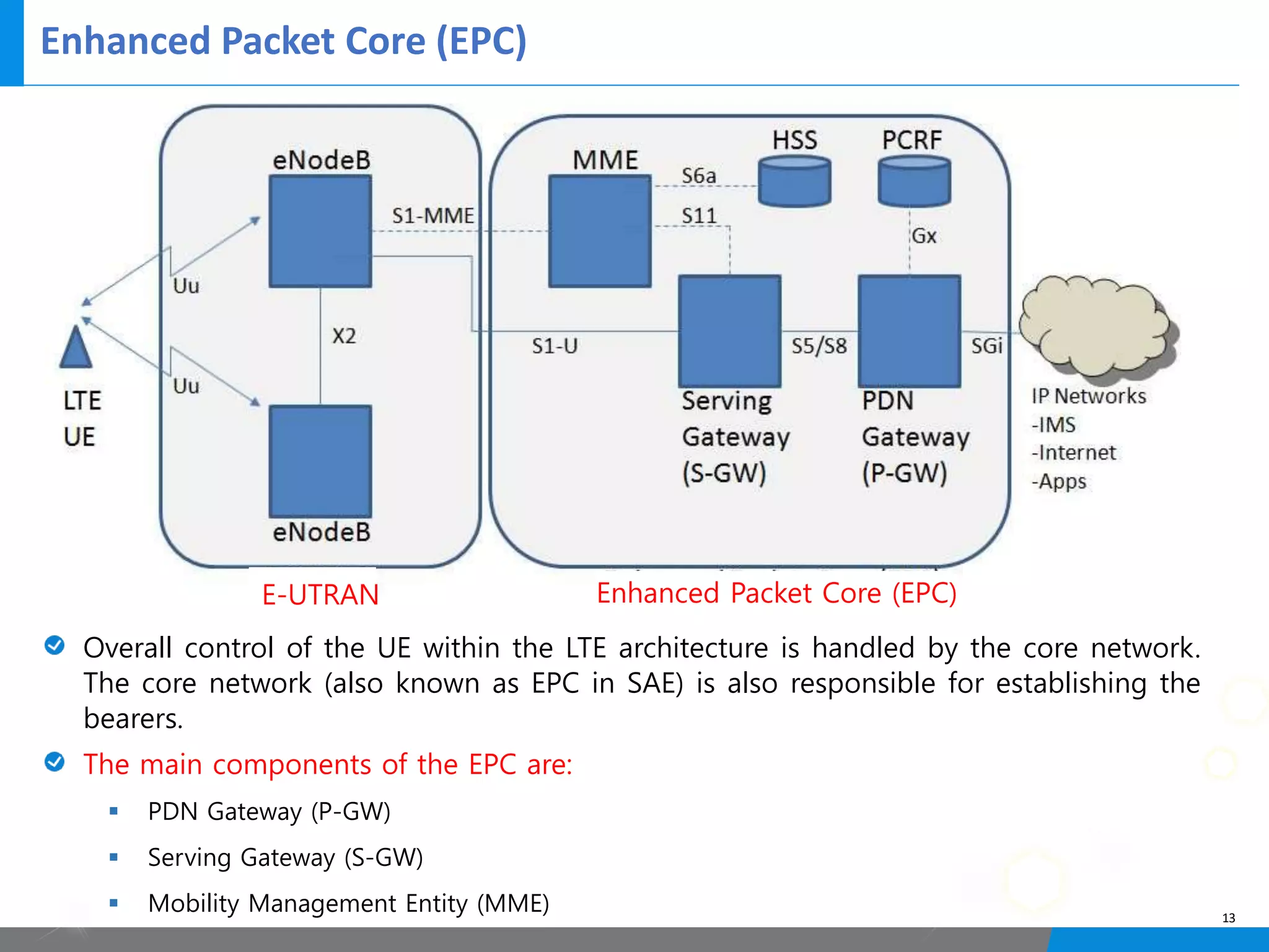
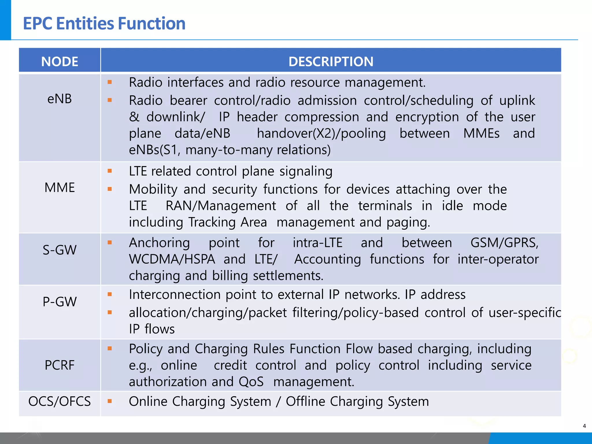
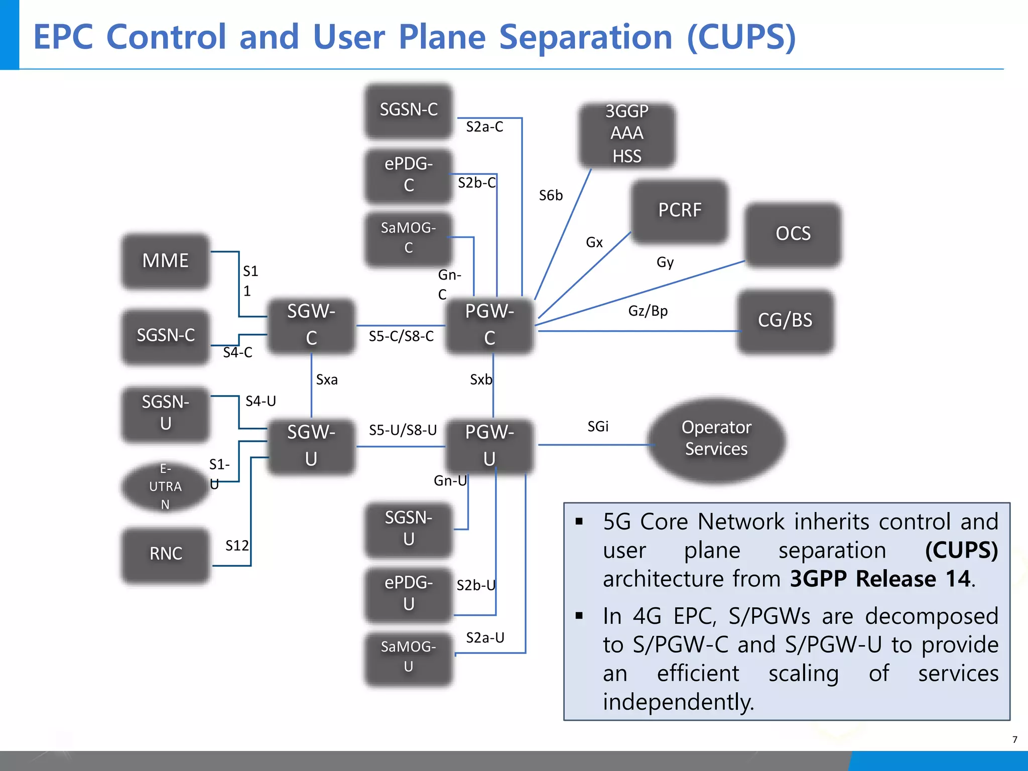
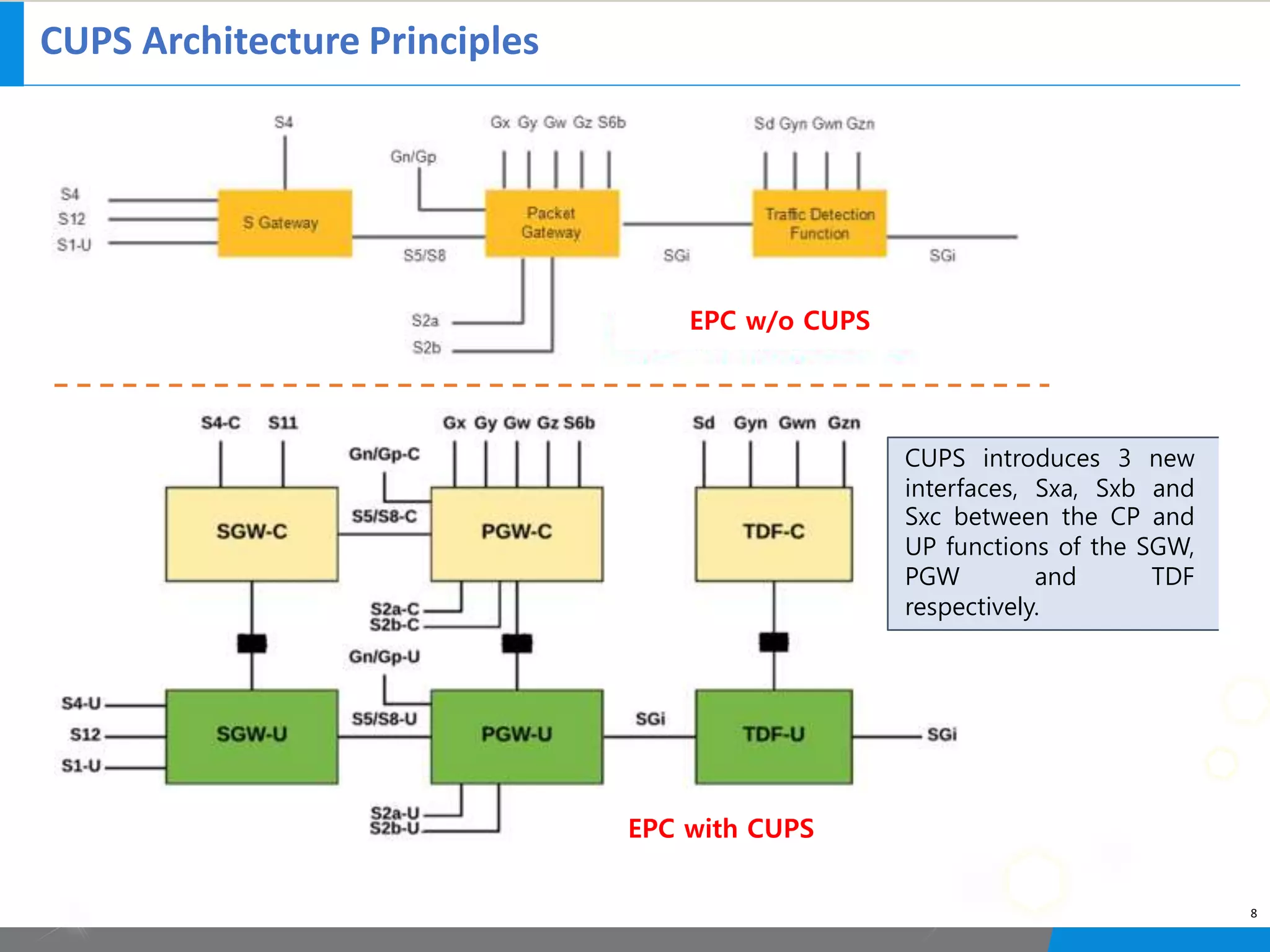
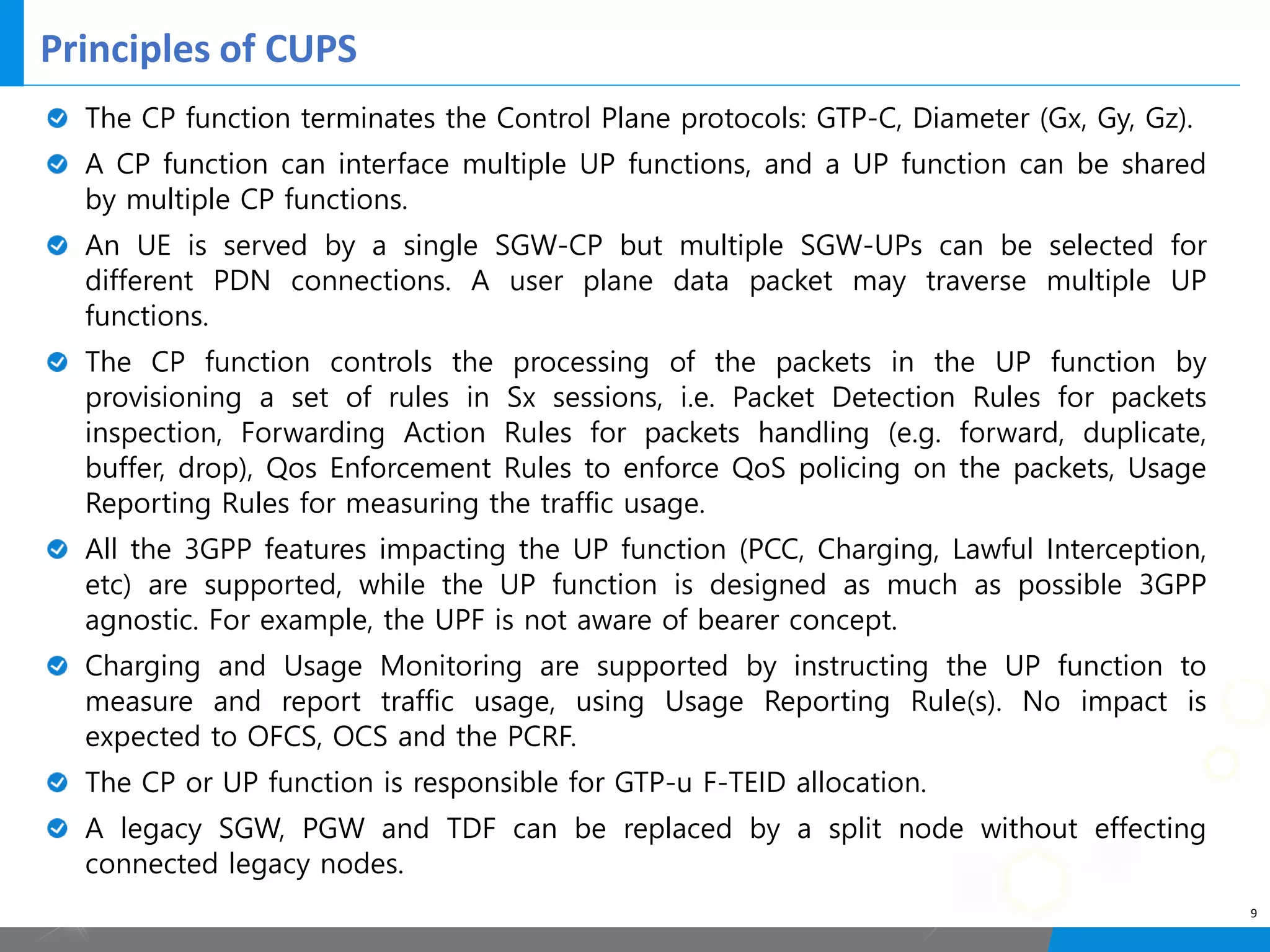
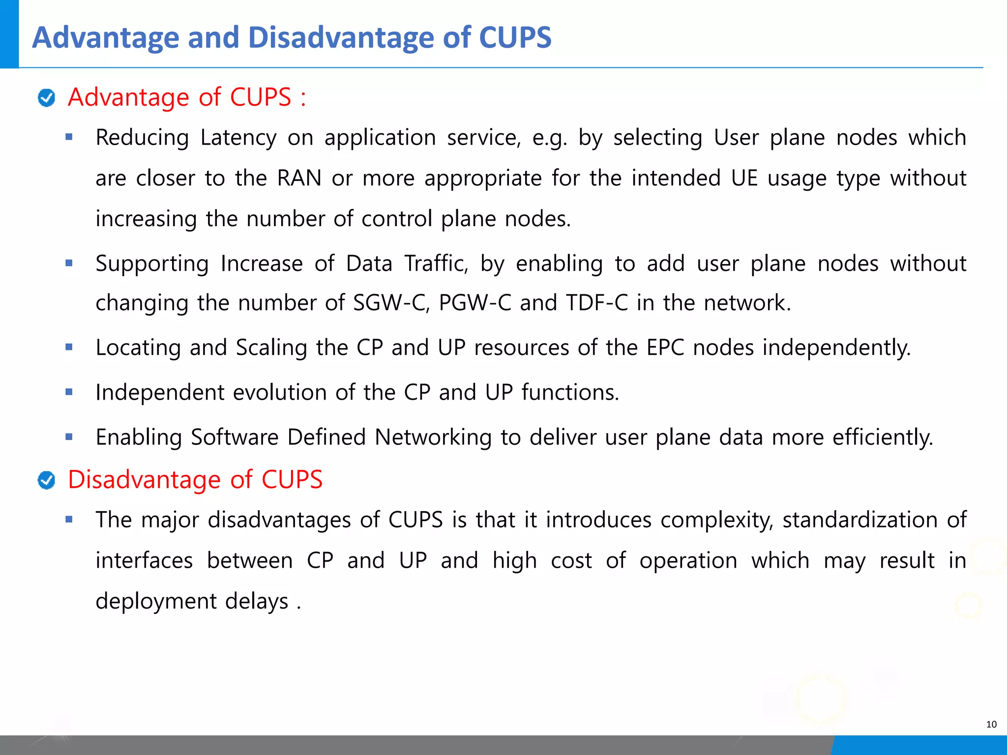
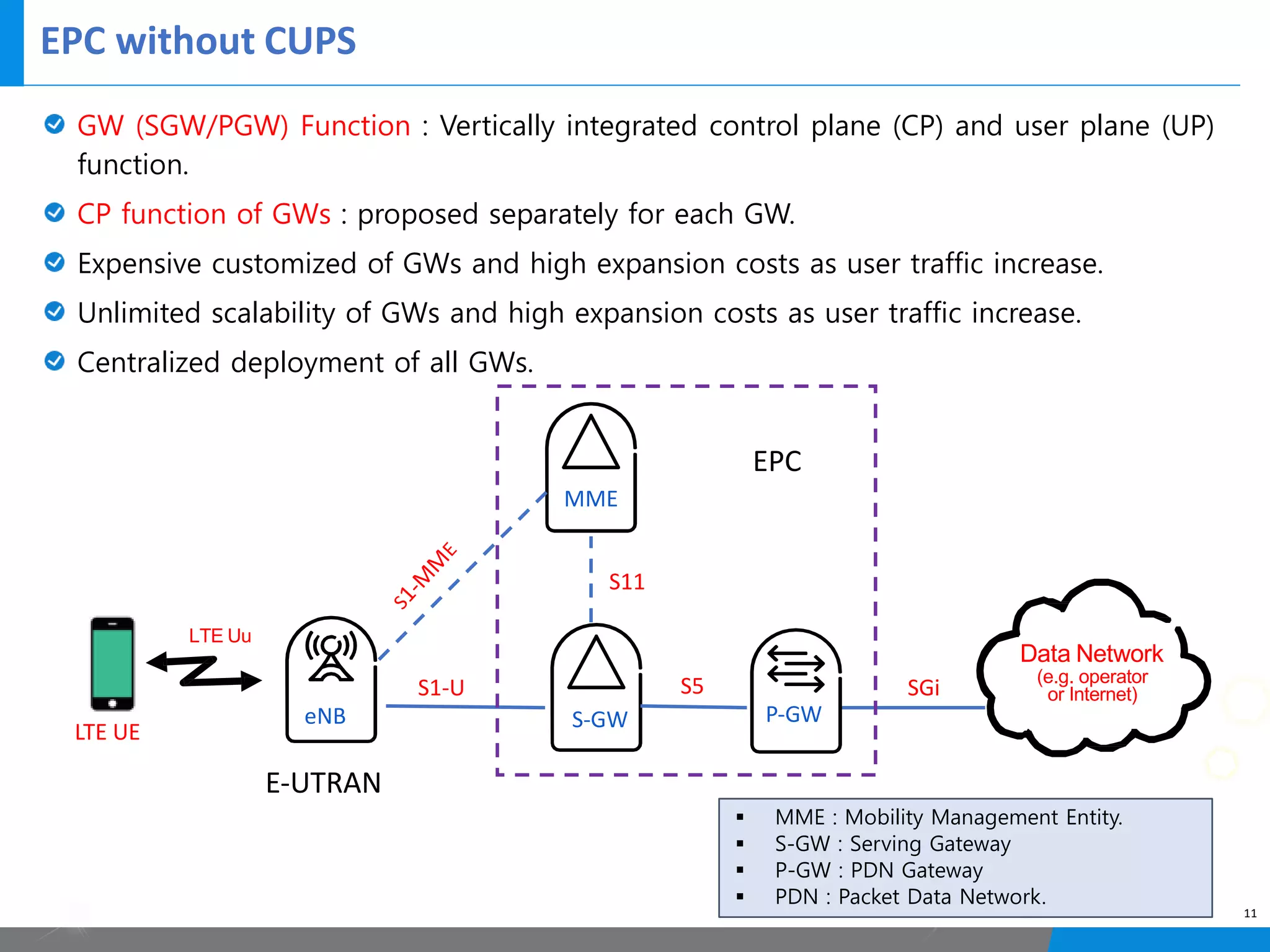
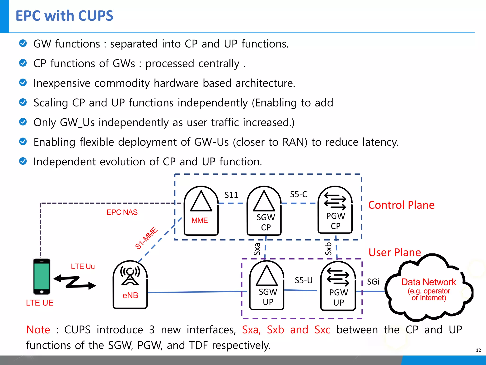
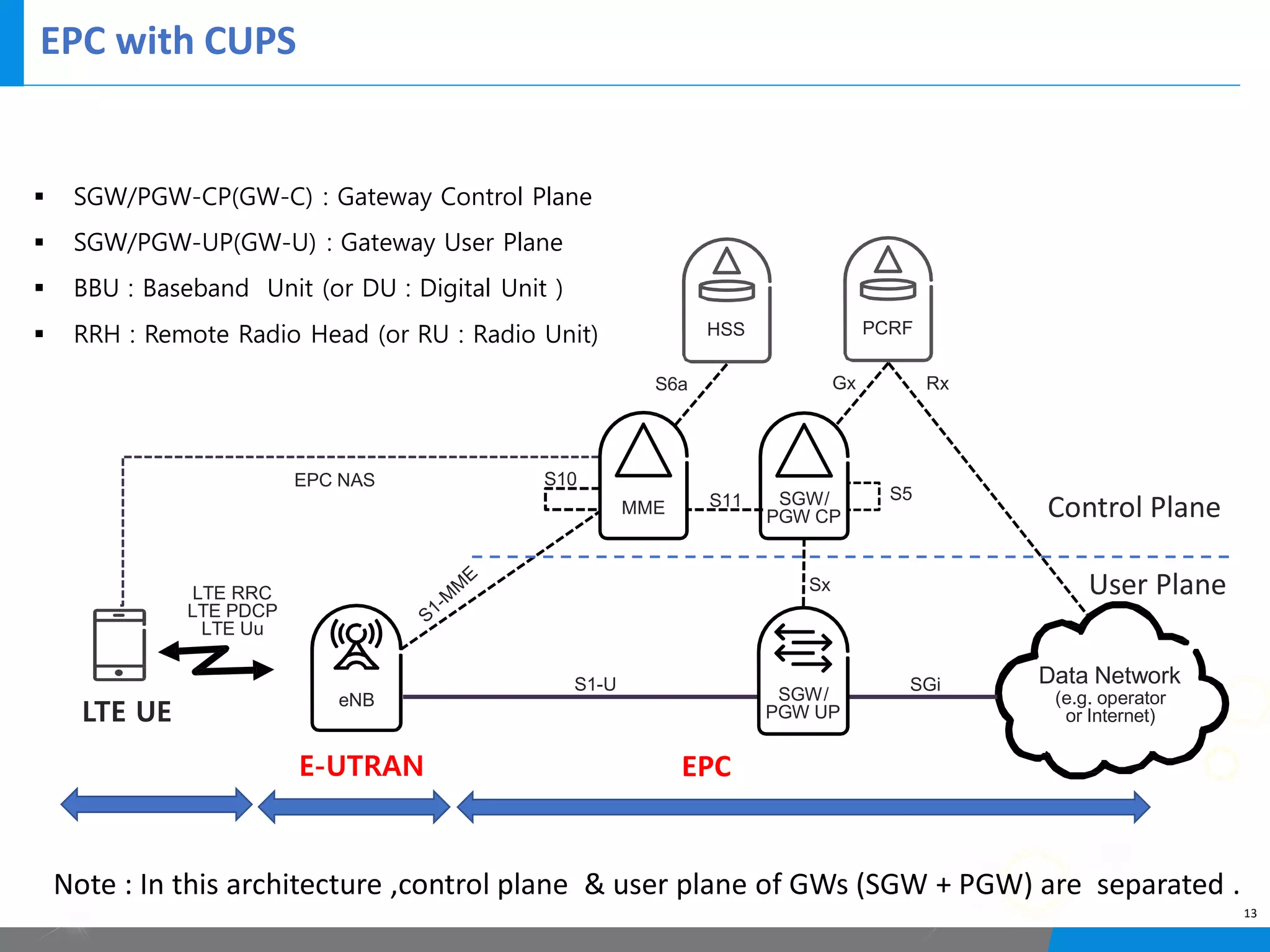

The document discusses EPC CUPS (Control and User Plane Separation) architecture in 3GPP releases. Some key points: 1) EPC CUPS was introduced in Release 14 to separate control and user plane functions for more flexible scaling and deployment. 2) CUPS introduces new Sxa, Sxb, and Sxc interfaces between control and user plane functions of SGW, PGW, and TDF. 3) The separation allows independent scaling of control and user plane resources to better handle increases in data traffic.