The document discusses various techniques for bus protection, including:
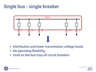
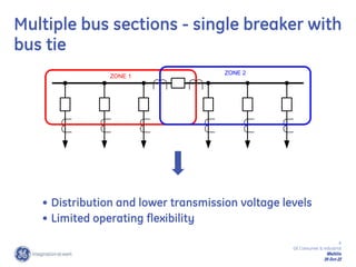
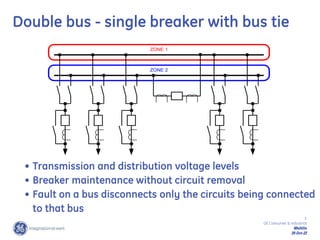
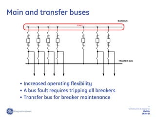
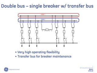
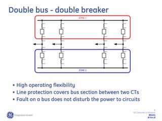
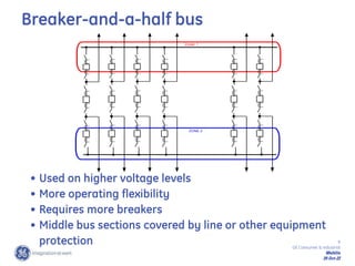
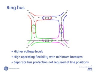
1) Different bus arrangements used in transmission and distribution systems and their protection challenges.
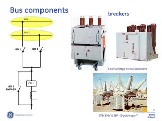
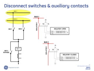
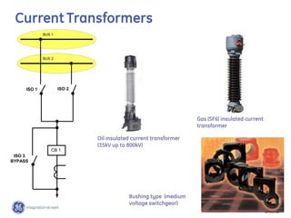
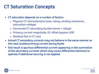
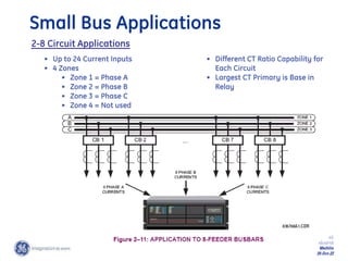
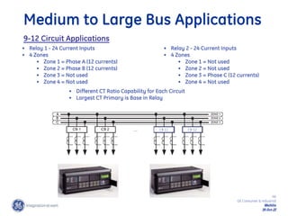
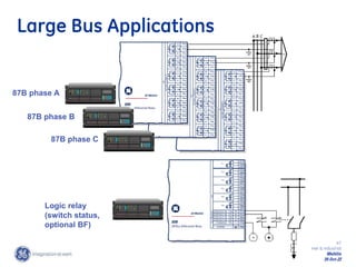
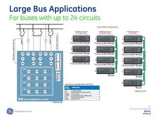
2) Components of bus protection systems including current transformers, circuit breakers, and disconnect switches.
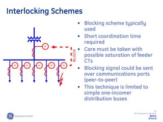
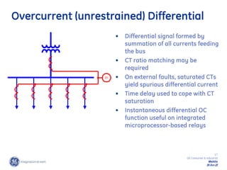
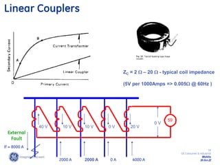
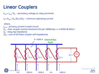
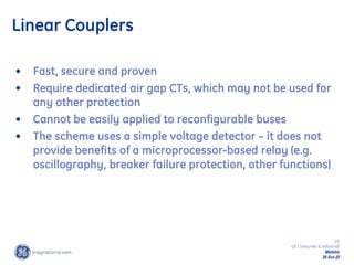
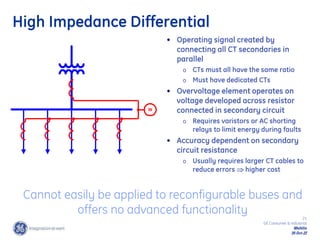
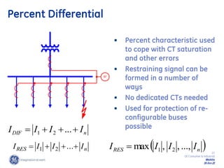
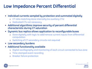
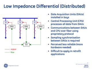
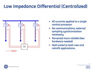
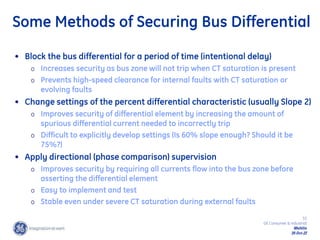
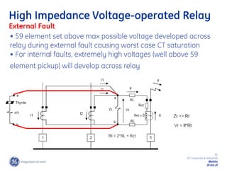
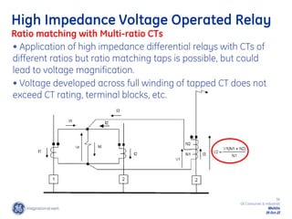
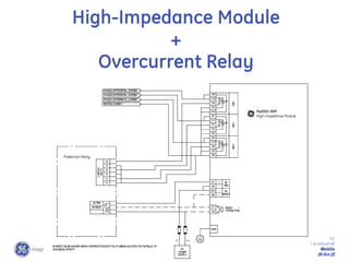
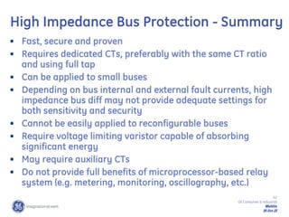
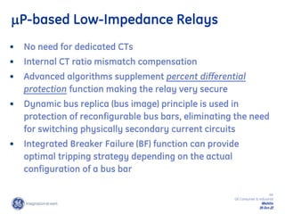
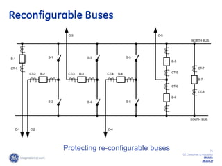
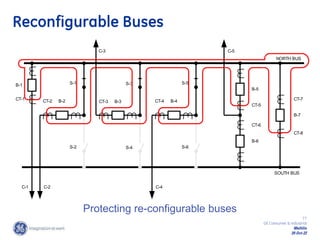
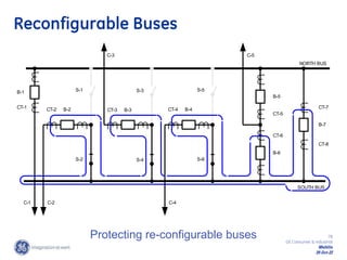
3) Various bus protection techniques including interlocking schemes, overcurrent differential, linear couplers, high-impedance differential, and low-impedance differential protection. It notes the advantages and disadvantages of each technique.