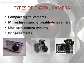
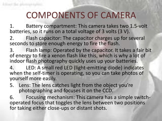
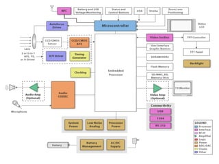
DIGITAL CAMERA
    ESD GROUP 3
WHAT IS DIGITAL CAMERA?
• A Digicam is a camera that takes videos or still
  photos by recording images on an electronic
  image sensor.
• Many digital cameras are incorporated into
  many devices ranging from PDA’s and mobile
  phones.
• They share an optical system using lens with
  variable diaphragm to focus light on image
  pickup device.
• light reflected from an object enters the
  camera and passes through convex lens that
  captures the image.
• Early cameras used the PC serial port. USB is
  now most widely method though some has
  fire-wire port.
• The other cameras used wireless
  communication such as Bluetooth 802.11.
• Pressing the button of camera opens the
  shutter so the light from the object travels to
  the back of the camera instead.
• For most a conversion to digital is required to
  give enough space for electronics and allow a
  LCD to preview the image and replacing it with
  built digital unit.
HOW DIGITAL CAMERA WORKS?
• It converts analog information (represented by
  fluctuated wave) into digital
  information(represented by ones and zeros or
  bits)
• Once a picture is taken image pic must be
  converted into a form that computer can
  recognize (bits and bytes)
• A digicam has different lenses that helps to
  focus the light to create image of the scene
• Digicams uses CCDs (charged coupled devices)
  or CMOS.
• CCD sensors create high quality low noise
  images but CMOS sensors are more
  susceptible to noise.
• Lets have a look what is the real difference
SIMPLE DIGITAL CAMERA
• Captures images
• Stores images in digital format
     – No film
     – Multiple images stored in camera
         • Number depends on amount of memory and bits used per image
• Downloads images to PC
• Only recently possible
     – Systems-on-a-chip
         • Multiple processors and memories on one IC
     – High-capacity flash memory
• Very simple description used for example
     – Many more features with real digital camera
         • Variable size images, image deletion, digital stretching, zooming in and out, etc.


 7
TYPES OF DIGITAL CAMERA
•   Compact digital cameras
•   Mirror less interchangeable-lens camera
•   Line-scan camera systems
•   Bridge cameras
HOW DO DIGITAL CAMERAS
          CAPTURE COLOR?
• To get full color of an image, most sensors use
  filtering to look at the light in its three primary
  colors
• All three colors get recorded and combined to
  create the full spectrum
• Beam splitter – directs light to different
  sensors and each sensor only responds to one
  of the primary colors
EXPOSURE AND FOCUS
• Digital camera has to control the amount
  of light that reaches the sensor.
• The two components it uses to do this, the
  aperture and shutter speed, and are also
  present on conventional cameras.
• Aperture: The size of the opening in the
  camera. The aperture is automatic in most
  digital cameras, but some allow manual
  adjustment to give professionals and
  hobbyists more control over the final
  image.
• Shutter speed: The amount of time that
  light can pass through the aperture. Unlike
  film, the light sensor in a digital camera
  can be reset electronically, so digital
  cameras have a digital shutter rather
  than a mechanical shutter
STORAGE
• Many camera phones and most separate
  digital cameras use memory cards having flash
  memory to store image data.
• The majority of cards for separate cameras are
  SD format; many are CompactFlash and the
  other formats are rare.
• Digital cameras have computers inside, hence
  have internal memory.
• A few cameras use some other form of
  removable storage such as Microdrive's (very
  small hard disk drives), CD single (185 MB),
  and 3.5" floppy disks. Other unusual formats
  include:
• Onboard flash memory — Cheap cameras and
  cameras secondary to the device's main use
  (such as a camera phone)
• PC Card hard drives — early professional
  cameras thermal printer — known only in one
  model of camera that printed images
  immediately rather than storing.
PIXEL RESOLUTION OF A DIGITAL CAMERA
• The clarity of the photos taken from a digital
  camera depends on the resolution of the
  camera.
• This resolution is always measured in the
  pixels.
• If the numbers of pixels are more, the
  resolution increases, thereby increasing the
  picture quality.
• There are many type of resolutions available
  for cameras. They differ mainly in the price.
TYPES OF PIXELS
• 256×256 – This is the basic resolution a
  camera has.
• 640×480-These type of cameras are suitable
  for posting pics and images in websites.
• 1216×912 – This resolution is normally used in
  studios for printing pictures.
• 2240×1680 – This is commonly referred to as a
  4 megapixel cameras.
• There are even higher resolution cameras up
  to 20 million pixels or so.
DESIGNER’S PERSPECTIVE
• Two key tasks
     – Processing images and storing in memory
       • When shutter pressed:
          – Image captured
          – Converted to digital form by charge-coupled device (CCD)
          – Compressed and archived in internal memory
     – Uploading images to PC
       • Digital camera attached to PC
       • Special software commands camera to transmit archived
         images serially

17
CHARGE-COUPLED DEVICE (CCD)
• Special sensor that captures an image
• Light-sensitive silicon solid-state device composed of many cells

     When exposed to light, each
     cell becomes electrically                                       The electromechanical
     charged. This charge can             Lens                       shutter is activated to expose
     then be converted to a 8-bit                                    the cells to light for a brief
                                          area
     value where 0 represents no              Covered   Electro-     moment.
                                                        mechanical
     exposure while 255                       columns   shutter
     represents very intense                                         The electronic circuitry, when
     exposure of that cell to light.                                 commanded, discharges the
                                                        Electronic
                                       rows
                                       Pixel


                                                        circuitry    cells, activates the
     Some of the columns are                                         electromechanical shutter,
     covered with a black strip of                                   and then reads the 8-bit
     paint. The light-intensity of                                   charge value of each cell.
     these pixels is used for zero-                                  These values can be clocked
     bias adjustments of all the           Pixel                     out of the CCD by external
     cells.                                columns                   logic through a standard
                                                                     parallel bus interface.


18
• The light falling on a cell is converted into small
  amount of electric charge which is measured by
  electronics and stored as a number.
• On periphery screen is composed of
  electromechanical shutter. When activated
  screen opens momentarily and allows light to hit
  the light sensitive surface.
• In a digital device, the voltages are sampled,
  digitized, and usually stored in memory; in an
  analog device (such as an analog video camera)
• They are processed into a continuous analog
  signal (e.g. by feeding the output of the charge
  amplifier into a low-pass filter) which is then
  processed and fed out to other circuits for
  transmission, recording, or other processing.
WHAT’S THE REAL DIFFERENCE
•   Because each pixel on a CMOS     • CCD sensors create high-
    sensor has several transistors     quality, low-noise images.
    located next to it, the light      CMOS sensors are generally
    sensitivity of a CMOS chip is      more susceptible to noise.
    lower. Many of the photons hit
    the transistors instead of the
    photodiode.

•   CMOS sensors traditionally       • CCD sensors have been mass
    consume little power. CCDs, on     produced for a longer period of
    the other hand, use a process      time, so they are more mature.
    that consumes lots of power.       They tend to have higher
    CCDs consume as much as 100
    times more power than an           quality pixels, and more of
    equivalent CMOS sensor.            them.
ZERO-BIAS ERROR
• Manufacturing errors cause cells to measure slightly above or below actual
  light intensity
• Error typically same across columns, but different across rows
• Some of left most columns blocked by black paint to detect zero-bias error
     – Reading of other than 0 in blocked cells is zero-bias error
     – Each row is corrected by subtracting the average error found in blocked cells
       for that row
                              Covered Zero
                              cells      Bias
     136   170   155   140   144   115   112   248 12   14   -13   123   157   142   127   131   102    99   235
     145   146   168   123   120   117   119   147 12   10   -11   134   135   157   112   109   106   108   136
     144   153   168   117   121   127   118   135 9     9    -9   135   144   159   108   112   118   109   126
     176   183   161   111   186   130   132   133 0     0     0   176   183   161   111   186   130   132   133
     144   156   161   133   192   153   138   139 7     7    -7   137   149   154   126   185   146   131   132
     122   131   128   147   206   151   131   127 2     0    -1   121   130   127   146   205   150   130   126
     121   155   164   185   254   165   138   129 4     4    -4   117   151   160   181   250   161   134   125
     173   175   176   183   188   184   117   129 5     5    -5   168   170   171   178   183   179   112   124

            Before zero-bias adjustment                             After zero-bias adjustment


22
COMPRESSION
• Store more images
• Transmit image to PC in less time
• JPEG (Joint Photographic Experts Group)
     – Popular standard format for representing digital images in a
       compressed form
     – Provides for a number of different modes of operation
     – Mode used provides high compression ratios using DCT (discrete
       cosine transform)
     – Image data divided into blocks of 8 x 8 pixels
     – 3 steps performed on each block
         • DCT
         • Quantization
         • Huffman encoding


23
DCT STEP
• Transforms original 8 x 8 block into a cosine-
  frequency domain
     – Upper-left corner values represent more of the essence of the image
     – Lower-right corner values represent finer details
          • Can reduce precision of these values and retain reasonable image quality
• FDCT (Forward DCT) formula
     – C(h) = if (h == 0) then 1/sqrt(2) else 1.0
          • Auxiliary function used in main function F(u,v)
     – F(u,v) = ¼ x C(u) x C(v) Σx=0..7 Σy=0..7 Dxy x cos(π(2u + 1)u/16) x cos(π(2y + 1)v/16)
          • Gives encoded pixel at row u, column v
          • Dxy is original pixel value at row x, column y

• IDCT (Inverse DCT)
     – Reverses process to obtain original block (not needed for this design)


24
QUANTIZATION STEP
• Achieve high compression ratio by reducing image
  quality
     – Reduce bit precision of encoded data
            • Fewer bits needed for encoding
            • One way is to divide all values by a factor of 2
                  – Simple right shifts can do this
     – Dequantization would reverse process for
       decompression
     1150    39 -43   -10   26   -83    11    41                        144    5   -5   -1    3   -10    1    5
      -81    -3 115   -73   -6    -2    22    -5
                                                   Divide each cell’s   -10    0   14   -9   -1     0    3   -1
       14   -11   1   -42   26    -3    17   -38   value by 8             2   -1    0   -5    3     0    2   -5
        2   -61 -13   -12   36   -23   -18     5                          0   -8   -2   -2    5    -3   -2    1
       44    13 37     -4   10   -21     7    -8                          6    2    5   -1    1    -3    1   -1
       36   -11  -9    -4   20   -28   -21    14                          5   -1   -1   -1    3    -4   -3    2
      -19    -7 21     -6    3     3    12   -21                         -2   -1    3   -1    0     0    2   -3
       -5   -13 -11   -17   -4    -1     7    -4                         -1   -2   -1   -2   -1     0    1   -1

     After being decoded using DCT                                      After quantization


25
HUFFMAN ENCODING STEP
• Serialize 8 x 8 block of pixels
     – Values are converted into single list using zigzag pattern


• Perform Huffman encoding
     – More frequently occurring pixels assigned short binary code
     – Longer binary codes left for less frequently occurring pixels
• Each pixel in serial list converted to Huffman encoded values
     – Much shorter list, thus compression


26
HUFFMAN ENCODING EXAMPLE
• Pixel frequencies on left
       – Pixel value –1 occurs 15 times
       – Pixel value 14 occurs 1 time
• Build Huffman tree from bottom up
       – Create one leaf node for each pixel value and assign frequency as node’s
         value
       – Create an internal node by joining any two nodes whose sum is a minimal
         value
           • This sum is internal nodes value
       – Repeat until complete binary tree
• Traverse tree from root to leaf to obtain binary code for leaf’s
  pixel value
       – Append 0 for left traversal, 1 for right traversal
• Huffman encoding is reversible
  27   – No code is a prefix of another code
Huffman codes
Pixel frequencies                              Huffman tree


                                                                    64
    -1 15x                                                                                                                                           -1   00

    0   8x                                                                                          35
                                                                                                                                                     0    100

    -2 6x                                 29
                                                                                                                                                     -2   110

    1   5x                                                                                                                                           1    010

    2   5x                                                                                                                                           2    1110
                                                                                                                         17
                                                                                 18
    3   5x               15
                                               14
                                                                                                                                                     3    1010

    5   5x                                                                                                                                           5    0110
                    -1                                                                                                        11                     -3   11110
    -3 4x                                           9
                                                                                      10

                              5
                                                                    8                                        6                                       -5   10110
    -5 3x
                     1                                          0                                    -2                                             -10   01110
   -10 2x
                                                        4                                  5                                       6                144   111111
   144 1x                         5                                     5                                        5
    -9 1x                                                                                                2                                           -9   111110
                          5                                         3
    -8 1x                                                                                  2                                           2             -8   101111
                                                            2                3                                       4
    -4 1x                             2                                                                                                              -4   101110
                         -10                                            -5                                   -3                                      6    011111
    6   1x
                                                1                                 1            1                          1                1        14
   14 1x                                                        1                                                                                         011110
                                           14                                    -4            -8                        -9                144
                                                                6
COMPONENTS OF CAMERA
1.      Battery compartment: This camera takes two 1.5-volt
batteries, so it runs on a total voltage of 3 volts (3 V).
2.      Flash capacitor: The capacitor charges up for several
seconds to store enough energy to fire the flash.
3.      Flash lamp: Operated by the capacitor. It takes a fair bit
of energy to fire a xenon flash like this, which is why a lot of
indoor flash photography quickly uses up your batteries.
4.      LED: A small red LED (light-emitting diode) indicates
when the self-timer is operating, so you can take photos of
yourself more easily.
5. Lens: The lens catches light from the object you're
     photographing and focuses it on the CCD.
6.      Focusing mechanism: This camera has a simple switch-
operated focus that toggles the lens between two positions
for taking either close-ups or distant shots.
7.       CCD: This is the light-detecting microchip in a digital
camera. You can't actually see the CCD in this photo, because it's
directly underneath the lens. But you can see what it looks like in
our article on how CCDs work.
8.       USB connector: Attach a USB cable here and connect it to
your computer to download the photos you've taken. To your
computer, your camera looks like just another memory device
(like a hard drive or a flash memory).
9.       SD (secure digital) card slot: You can slide a flash memory
card in here for storing more photos. The camera has a very
small internal memory that will store photos too.
10.      Processor chip: The camera's main digital "brain". This
controls all the camera's functions. It's an example of an
integrated circuit.
11.      Wrist connector: The strap that keeps the camera
securely tied to your wrist attaches here.
12.      Top case: Simply screws on top of the bottom case shown
here.
BLOCK DIAGRAM
WHY PREFER ARM CORTEX M3?
• With high performance and low dynamic power
  consumption the Cortex-M3 processor delivers leading
  power efficiency 12.5 DMIPS / mW based on 90nmG.
• The processor executes Thumb®-2 instruction set for
  optimal performance and code size.
• It including hardware division, single cycle multiply,
  and bit-field manipulation.
• The Cortex-M3 NVIC is highly configurable at design
  time to deliver up to 240 system interrupts.
FEATURES OF ARM CORTEX
                       TMPM365FYXBG
• Operating voltage:
  2.7 to 3.6V (Single supply 3.0 to 3.45V when USB is used)
• Maximum Operating frequency:
  48 MHz
• On-chip debug circuit:
  JTAG, SWD, SWV or 4-bit trace interface
• Power saving operation
  Clock gear (for dividing clock to 1/1, 1/2, 1/4, 1/8 or 1/16)
  Standby modes (IDLE, STOP1)
• ARM cortex M is a group of 32 bit RISC processor cores
  licensed by Arm holdings intended for microcontroller
  applications
• 3 stage pipeline is used.
BUILT-IN FUNCTIONS
• USB(Full-Speed) : 1 channel
• 12-bit AD converter :
  1µsec conversion time(@fsys=40MHz) 12 channels
• DMA controller : 2 channels
• I/O ports : 74 pins
• 16-bit timer : 10 channels
• SIO/UART : 2 channels
• I2C(100kHz,400kHz)/SIO : 2 channels
JOINT TEST ACTION GROUP (JTAG)
• It is the common name for the IEEE 1149.1
  Standard Test Access Port and Boundary-Scan
  Architecture.
• Today JTAG is also widely used for IC debug ports.
• On most systems, JTAG-based debugging is
  available from the very first instruction after CPU
  reset, letting it assist with development of early
  boot software which runs before anything is set
  up.
16-BIT TIMER
• The TIMERS are divided into two 8-bit SFR called Timer
  LOW (TL0, TL1) & Timer HIGH (TH0, TH1) these
  registers contain the latest count of the TIMER.
• The TIMER action is controlled by two more SFR's
  called Timer Mode Control Register(TMOD)
  & Timer/Counter Control Register (TCON).
• TMOD is dedicated to the two Timers & controls the
  mode of operation of both the Timers.
• It can be considered as two duplicate 4 bit register,
  where the high 4 bits controls Timer 1 & the lower 4
  bits controls Timer 0.
THE PHYSICAL I2C BUS
• This is just two wires, called SCL and SDA. SCL is the clock line. It is
  used to synchronize all data transfers over the I2C bus.
• SDA is the data line. The SCL & SDA lines are connected to all
  devices on the I2C bus.
• There needs to be a third wire which is just the ground or 0 volts.
  There may also be a 5volt wire is power is being distributed to the
  devices. Both SCL and SDA lines are "open drain" drivers. What this
  means is that the chip can drive its output low, but it cannot drive it
  high.
• For the line to be able to go high you must provide pull-up resistors
  to the 5v supply. There should be a resistor from the SCL line to the
  5v line and another from the SDA line to the 5v line.
• You only need one set of pull-up resistors for the whole I2C bus, not
  for each device, as illustrated below:
SOFTWARE USED
Keil u vision (IDE).

• Tools:
  Real View MDK-ARM, ULINK2 - USB-JTAG Debugger.
  Real View Real-Time Library (RL-ARM).
• Types of Target Debugging, Serial Wire Debugger for
  Cortex

  CortexM3 – Core sight Debugger

  ULINK2 - USB-JTAG Debug Adaptor
Future of Digital camera
• Smart camera- Application enhanced cameras
  along with the ability to access various apps,
  internet, compact like Galaxy camera
• Not only it gives a full interactive photographic
  capabilities but also keeps you connected via
  internet.
• You can directly post the pictures taken to
  Facebook etc. along with interactive media . Its
  just like a merged up high end smart phone with
  a smart camera
• iris-cameras is at a developing stage everyone has
  seen the glimpse of it in Mission impossible 4
THANK YOU

Digital camera

  • 1.
    DIGITAL CAMERA ESD GROUP 3
  • 2.
    WHAT IS DIGITALCAMERA? • A Digicam is a camera that takes videos or still photos by recording images on an electronic image sensor. • Many digital cameras are incorporated into many devices ranging from PDA’s and mobile phones. • They share an optical system using lens with variable diaphragm to focus light on image pickup device.
  • 3.
    • light reflectedfrom an object enters the camera and passes through convex lens that captures the image. • Early cameras used the PC serial port. USB is now most widely method though some has fire-wire port. • The other cameras used wireless communication such as Bluetooth 802.11. • Pressing the button of camera opens the shutter so the light from the object travels to the back of the camera instead.
  • 4.
    • For mosta conversion to digital is required to give enough space for electronics and allow a LCD to preview the image and replacing it with built digital unit.
  • 5.
    HOW DIGITAL CAMERAWORKS? • It converts analog information (represented by fluctuated wave) into digital information(represented by ones and zeros or bits) • Once a picture is taken image pic must be converted into a form that computer can recognize (bits and bytes) • A digicam has different lenses that helps to focus the light to create image of the scene
  • 6.
    • Digicams usesCCDs (charged coupled devices) or CMOS. • CCD sensors create high quality low noise images but CMOS sensors are more susceptible to noise. • Lets have a look what is the real difference
  • 7.
    SIMPLE DIGITAL CAMERA •Captures images • Stores images in digital format – No film – Multiple images stored in camera • Number depends on amount of memory and bits used per image • Downloads images to PC • Only recently possible – Systems-on-a-chip • Multiple processors and memories on one IC – High-capacity flash memory • Very simple description used for example – Many more features with real digital camera • Variable size images, image deletion, digital stretching, zooming in and out, etc. 7
  • 8.
    TYPES OF DIGITALCAMERA • Compact digital cameras • Mirror less interchangeable-lens camera • Line-scan camera systems • Bridge cameras
  • 10.
    HOW DO DIGITALCAMERAS CAPTURE COLOR? • To get full color of an image, most sensors use filtering to look at the light in its three primary colors • All three colors get recorded and combined to create the full spectrum • Beam splitter – directs light to different sensors and each sensor only responds to one of the primary colors
  • 11.
    EXPOSURE AND FOCUS •Digital camera has to control the amount of light that reaches the sensor. • The two components it uses to do this, the aperture and shutter speed, and are also present on conventional cameras.
  • 12.
    • Aperture: Thesize of the opening in the camera. The aperture is automatic in most digital cameras, but some allow manual adjustment to give professionals and hobbyists more control over the final image. • Shutter speed: The amount of time that light can pass through the aperture. Unlike film, the light sensor in a digital camera can be reset electronically, so digital cameras have a digital shutter rather than a mechanical shutter
  • 13.
    STORAGE • Many cameraphones and most separate digital cameras use memory cards having flash memory to store image data. • The majority of cards for separate cameras are SD format; many are CompactFlash and the other formats are rare. • Digital cameras have computers inside, hence have internal memory.
  • 14.
    • A fewcameras use some other form of removable storage such as Microdrive's (very small hard disk drives), CD single (185 MB), and 3.5" floppy disks. Other unusual formats include: • Onboard flash memory — Cheap cameras and cameras secondary to the device's main use (such as a camera phone) • PC Card hard drives — early professional cameras thermal printer — known only in one model of camera that printed images immediately rather than storing.
  • 15.
    PIXEL RESOLUTION OFA DIGITAL CAMERA • The clarity of the photos taken from a digital camera depends on the resolution of the camera. • This resolution is always measured in the pixels. • If the numbers of pixels are more, the resolution increases, thereby increasing the picture quality. • There are many type of resolutions available for cameras. They differ mainly in the price.
  • 16.
    TYPES OF PIXELS •256×256 – This is the basic resolution a camera has. • 640×480-These type of cameras are suitable for posting pics and images in websites. • 1216×912 – This resolution is normally used in studios for printing pictures. • 2240×1680 – This is commonly referred to as a 4 megapixel cameras. • There are even higher resolution cameras up to 20 million pixels or so.
  • 17.
    DESIGNER’S PERSPECTIVE • Twokey tasks – Processing images and storing in memory • When shutter pressed: – Image captured – Converted to digital form by charge-coupled device (CCD) – Compressed and archived in internal memory – Uploading images to PC • Digital camera attached to PC • Special software commands camera to transmit archived images serially 17
  • 18.
    CHARGE-COUPLED DEVICE (CCD) •Special sensor that captures an image • Light-sensitive silicon solid-state device composed of many cells When exposed to light, each cell becomes electrically The electromechanical charged. This charge can Lens shutter is activated to expose then be converted to a 8-bit the cells to light for a brief area value where 0 represents no Covered Electro- moment. mechanical exposure while 255 columns shutter represents very intense The electronic circuitry, when exposure of that cell to light. commanded, discharges the Electronic rows Pixel circuitry cells, activates the Some of the columns are electromechanical shutter, covered with a black strip of and then reads the 8-bit paint. The light-intensity of charge value of each cell. these pixels is used for zero- These values can be clocked bias adjustments of all the Pixel out of the CCD by external cells. columns logic through a standard parallel bus interface. 18
  • 19.
    • The lightfalling on a cell is converted into small amount of electric charge which is measured by electronics and stored as a number.
  • 20.
    • On peripheryscreen is composed of electromechanical shutter. When activated screen opens momentarily and allows light to hit the light sensitive surface. • In a digital device, the voltages are sampled, digitized, and usually stored in memory; in an analog device (such as an analog video camera) • They are processed into a continuous analog signal (e.g. by feeding the output of the charge amplifier into a low-pass filter) which is then processed and fed out to other circuits for transmission, recording, or other processing.
  • 21.
    WHAT’S THE REALDIFFERENCE • Because each pixel on a CMOS • CCD sensors create high- sensor has several transistors quality, low-noise images. located next to it, the light CMOS sensors are generally sensitivity of a CMOS chip is more susceptible to noise. lower. Many of the photons hit the transistors instead of the photodiode. • CMOS sensors traditionally • CCD sensors have been mass consume little power. CCDs, on produced for a longer period of the other hand, use a process time, so they are more mature. that consumes lots of power. They tend to have higher CCDs consume as much as 100 times more power than an quality pixels, and more of equivalent CMOS sensor. them.
  • 22.
    ZERO-BIAS ERROR • Manufacturingerrors cause cells to measure slightly above or below actual light intensity • Error typically same across columns, but different across rows • Some of left most columns blocked by black paint to detect zero-bias error – Reading of other than 0 in blocked cells is zero-bias error – Each row is corrected by subtracting the average error found in blocked cells for that row Covered Zero cells Bias 136 170 155 140 144 115 112 248 12 14 -13 123 157 142 127 131 102 99 235 145 146 168 123 120 117 119 147 12 10 -11 134 135 157 112 109 106 108 136 144 153 168 117 121 127 118 135 9 9 -9 135 144 159 108 112 118 109 126 176 183 161 111 186 130 132 133 0 0 0 176 183 161 111 186 130 132 133 144 156 161 133 192 153 138 139 7 7 -7 137 149 154 126 185 146 131 132 122 131 128 147 206 151 131 127 2 0 -1 121 130 127 146 205 150 130 126 121 155 164 185 254 165 138 129 4 4 -4 117 151 160 181 250 161 134 125 173 175 176 183 188 184 117 129 5 5 -5 168 170 171 178 183 179 112 124 Before zero-bias adjustment After zero-bias adjustment 22
  • 23.
    COMPRESSION • Store moreimages • Transmit image to PC in less time • JPEG (Joint Photographic Experts Group) – Popular standard format for representing digital images in a compressed form – Provides for a number of different modes of operation – Mode used provides high compression ratios using DCT (discrete cosine transform) – Image data divided into blocks of 8 x 8 pixels – 3 steps performed on each block • DCT • Quantization • Huffman encoding 23
  • 24.
    DCT STEP • Transformsoriginal 8 x 8 block into a cosine- frequency domain – Upper-left corner values represent more of the essence of the image – Lower-right corner values represent finer details • Can reduce precision of these values and retain reasonable image quality • FDCT (Forward DCT) formula – C(h) = if (h == 0) then 1/sqrt(2) else 1.0 • Auxiliary function used in main function F(u,v) – F(u,v) = ¼ x C(u) x C(v) Σx=0..7 Σy=0..7 Dxy x cos(π(2u + 1)u/16) x cos(π(2y + 1)v/16) • Gives encoded pixel at row u, column v • Dxy is original pixel value at row x, column y • IDCT (Inverse DCT) – Reverses process to obtain original block (not needed for this design) 24
  • 25.
    QUANTIZATION STEP • Achievehigh compression ratio by reducing image quality – Reduce bit precision of encoded data • Fewer bits needed for encoding • One way is to divide all values by a factor of 2 – Simple right shifts can do this – Dequantization would reverse process for decompression 1150 39 -43 -10 26 -83 11 41 144 5 -5 -1 3 -10 1 5 -81 -3 115 -73 -6 -2 22 -5 Divide each cell’s -10 0 14 -9 -1 0 3 -1 14 -11 1 -42 26 -3 17 -38 value by 8 2 -1 0 -5 3 0 2 -5 2 -61 -13 -12 36 -23 -18 5 0 -8 -2 -2 5 -3 -2 1 44 13 37 -4 10 -21 7 -8 6 2 5 -1 1 -3 1 -1 36 -11 -9 -4 20 -28 -21 14 5 -1 -1 -1 3 -4 -3 2 -19 -7 21 -6 3 3 12 -21 -2 -1 3 -1 0 0 2 -3 -5 -13 -11 -17 -4 -1 7 -4 -1 -2 -1 -2 -1 0 1 -1 After being decoded using DCT After quantization 25
  • 26.
    HUFFMAN ENCODING STEP •Serialize 8 x 8 block of pixels – Values are converted into single list using zigzag pattern • Perform Huffman encoding – More frequently occurring pixels assigned short binary code – Longer binary codes left for less frequently occurring pixels • Each pixel in serial list converted to Huffman encoded values – Much shorter list, thus compression 26
  • 27.
    HUFFMAN ENCODING EXAMPLE •Pixel frequencies on left – Pixel value –1 occurs 15 times – Pixel value 14 occurs 1 time • Build Huffman tree from bottom up – Create one leaf node for each pixel value and assign frequency as node’s value – Create an internal node by joining any two nodes whose sum is a minimal value • This sum is internal nodes value – Repeat until complete binary tree • Traverse tree from root to leaf to obtain binary code for leaf’s pixel value – Append 0 for left traversal, 1 for right traversal • Huffman encoding is reversible 27 – No code is a prefix of another code
  • 28.
    Huffman codes Pixel frequencies Huffman tree 64 -1 15x -1 00 0 8x 35 0 100 -2 6x 29 -2 110 1 5x 1 010 2 5x 2 1110 17 18 3 5x 15 14 3 1010 5 5x 5 0110 -1 11 -3 11110 -3 4x 9 10 5 8 6 -5 10110 -5 3x 1 0 -2 -10 01110 -10 2x 4 5 6 144 111111 144 1x 5 5 5 -9 1x 2 -9 111110 5 3 -8 1x 2 2 -8 101111 2 3 4 -4 1x 2 -4 101110 -10 -5 -3 6 011111 6 1x 1 1 1 1 1 14 14 1x 1 011110 14 -4 -8 -9 144 6
  • 30.
    COMPONENTS OF CAMERA 1. Battery compartment: This camera takes two 1.5-volt batteries, so it runs on a total voltage of 3 volts (3 V). 2. Flash capacitor: The capacitor charges up for several seconds to store enough energy to fire the flash. 3. Flash lamp: Operated by the capacitor. It takes a fair bit of energy to fire a xenon flash like this, which is why a lot of indoor flash photography quickly uses up your batteries. 4. LED: A small red LED (light-emitting diode) indicates when the self-timer is operating, so you can take photos of yourself more easily. 5. Lens: The lens catches light from the object you're photographing and focuses it on the CCD. 6. Focusing mechanism: This camera has a simple switch- operated focus that toggles the lens between two positions for taking either close-ups or distant shots.
  • 31.
    7. CCD: This is the light-detecting microchip in a digital camera. You can't actually see the CCD in this photo, because it's directly underneath the lens. But you can see what it looks like in our article on how CCDs work. 8. USB connector: Attach a USB cable here and connect it to your computer to download the photos you've taken. To your computer, your camera looks like just another memory device (like a hard drive or a flash memory). 9. SD (secure digital) card slot: You can slide a flash memory card in here for storing more photos. The camera has a very small internal memory that will store photos too. 10. Processor chip: The camera's main digital "brain". This controls all the camera's functions. It's an example of an integrated circuit. 11. Wrist connector: The strap that keeps the camera securely tied to your wrist attaches here. 12. Top case: Simply screws on top of the bottom case shown here.
  • 32.
  • 34.
    WHY PREFER ARMCORTEX M3? • With high performance and low dynamic power consumption the Cortex-M3 processor delivers leading power efficiency 12.5 DMIPS / mW based on 90nmG. • The processor executes Thumb®-2 instruction set for optimal performance and code size. • It including hardware division, single cycle multiply, and bit-field manipulation. • The Cortex-M3 NVIC is highly configurable at design time to deliver up to 240 system interrupts.
  • 36.
    FEATURES OF ARMCORTEX TMPM365FYXBG • Operating voltage: 2.7 to 3.6V (Single supply 3.0 to 3.45V when USB is used) • Maximum Operating frequency: 48 MHz • On-chip debug circuit: JTAG, SWD, SWV or 4-bit trace interface • Power saving operation Clock gear (for dividing clock to 1/1, 1/2, 1/4, 1/8 or 1/16) Standby modes (IDLE, STOP1) • ARM cortex M is a group of 32 bit RISC processor cores licensed by Arm holdings intended for microcontroller applications • 3 stage pipeline is used.
  • 37.
    BUILT-IN FUNCTIONS • USB(Full-Speed): 1 channel • 12-bit AD converter : 1µsec conversion time(@fsys=40MHz) 12 channels • DMA controller : 2 channels • I/O ports : 74 pins • 16-bit timer : 10 channels • SIO/UART : 2 channels • I2C(100kHz,400kHz)/SIO : 2 channels
  • 38.
    JOINT TEST ACTIONGROUP (JTAG) • It is the common name for the IEEE 1149.1 Standard Test Access Port and Boundary-Scan Architecture. • Today JTAG is also widely used for IC debug ports. • On most systems, JTAG-based debugging is available from the very first instruction after CPU reset, letting it assist with development of early boot software which runs before anything is set up.
  • 39.
    16-BIT TIMER • TheTIMERS are divided into two 8-bit SFR called Timer LOW (TL0, TL1) & Timer HIGH (TH0, TH1) these registers contain the latest count of the TIMER. • The TIMER action is controlled by two more SFR's called Timer Mode Control Register(TMOD) & Timer/Counter Control Register (TCON). • TMOD is dedicated to the two Timers & controls the mode of operation of both the Timers. • It can be considered as two duplicate 4 bit register, where the high 4 bits controls Timer 1 & the lower 4 bits controls Timer 0.
  • 40.
    THE PHYSICAL I2CBUS • This is just two wires, called SCL and SDA. SCL is the clock line. It is used to synchronize all data transfers over the I2C bus. • SDA is the data line. The SCL & SDA lines are connected to all devices on the I2C bus. • There needs to be a third wire which is just the ground or 0 volts. There may also be a 5volt wire is power is being distributed to the devices. Both SCL and SDA lines are "open drain" drivers. What this means is that the chip can drive its output low, but it cannot drive it high. • For the line to be able to go high you must provide pull-up resistors to the 5v supply. There should be a resistor from the SCL line to the 5v line and another from the SDA line to the 5v line. • You only need one set of pull-up resistors for the whole I2C bus, not for each device, as illustrated below:
  • 43.
    SOFTWARE USED Keil uvision (IDE). • Tools: Real View MDK-ARM, ULINK2 - USB-JTAG Debugger. Real View Real-Time Library (RL-ARM). • Types of Target Debugging, Serial Wire Debugger for Cortex CortexM3 – Core sight Debugger ULINK2 - USB-JTAG Debug Adaptor
  • 44.
    Future of Digitalcamera • Smart camera- Application enhanced cameras along with the ability to access various apps, internet, compact like Galaxy camera • Not only it gives a full interactive photographic capabilities but also keeps you connected via internet. • You can directly post the pictures taken to Facebook etc. along with interactive media . Its just like a merged up high end smart phone with a smart camera • iris-cameras is at a developing stage everyone has seen the glimpse of it in Mission impossible 4
  • 45.